KR101098259B1 - Laser scribe method and apparatus - Google Patents
Laser scribe method and apparatusDownload PDFInfo
- Publication number
- KR101098259B1 KR101098259B1KR1020100008305AKR20100008305AKR101098259B1KR 101098259 B1KR101098259 B1KR 101098259B1KR 1020100008305 AKR1020100008305 AKR 1020100008305AKR 20100008305 AKR20100008305 AKR 20100008305AKR 101098259 B1KR101098259 B1KR 101098259B1
- Authority
- KR
- South Korea
- Prior art keywords
- laser
- scribe
- light
- beams
- workpiece
- Prior art date
- Legal status (The legal status is an assumption and is not a legal conclusion. Google has not performed a legal analysis and makes no representation as to the accuracy of the status listed.)
- Active
Links
- 238000000034methodMethods0.000titleclaimsabstractdescription34
- 230000004907fluxEffects0.000claimsabstractdescription16
- 230000003287optical effectEffects0.000claimsdescription18
- 230000010287polarizationEffects0.000claimsdescription15
- 239000010453quartzSubstances0.000claimsdescription13
- VYPSYNLAJGMNEJ-UHFFFAOYSA-Nsilicon dioxideInorganic materialsO=[Si]=OVYPSYNLAJGMNEJ-UHFFFAOYSA-N0.000claimsdescription13
- 238000000926separation methodMethods0.000claimsdescription11
- 230000007246mechanismEffects0.000claimsdescription6
- 230000001678irradiating effectEffects0.000description8
- 238000010521absorption reactionMethods0.000description7
- 239000000463materialSubstances0.000description7
- 239000013078crystalSubstances0.000description5
- 230000002159abnormal effectEffects0.000description4
- 239000000919ceramicSubstances0.000description4
- 230000000052comparative effectEffects0.000description4
- 238000005259measurementMethods0.000description4
- 230000010355oscillationEffects0.000description4
- 230000008859changeEffects0.000description3
- 230000000694effectsEffects0.000description2
- 230000008569processEffects0.000description2
- 210000001747pupilAnatomy0.000description2
- 229910052594sapphireInorganic materials0.000description2
- 239000010980sapphireSubstances0.000description2
- 239000004065semiconductorSubstances0.000description2
- 229910052710siliconInorganic materials0.000description2
- 239000010703siliconSubstances0.000description2
- 238000001228spectrumMethods0.000description2
- PNEYBMLMFCGWSK-UHFFFAOYSA-Naluminium oxideInorganic materials[O-2].[O-2].[O-2].[Al+3].[Al+3]PNEYBMLMFCGWSK-UHFFFAOYSA-N0.000description1
- 230000008901benefitEffects0.000description1
- 230000015572biosynthetic processEffects0.000description1
- 230000002051biphasic effectEffects0.000description1
- 230000003247decreasing effectEffects0.000description1
- 238000010586diagramMethods0.000description1
- 239000000835fiberSubstances0.000description1
- 230000006870functionEffects0.000description1
- 230000031700light absorptionEffects0.000description1
- 239000012466permeateSubstances0.000description1
- 239000007787solidSubstances0.000description1
- 239000000758substrateSubstances0.000description1
Images


Classifications
- H—ELECTRICITY
- H01—ELECTRIC ELEMENTS
- H01L—SEMICONDUCTOR DEVICES NOT COVERED BY CLASS H10
- H01L21/00—Processes or apparatus adapted for the manufacture or treatment of semiconductor or solid state devices or of parts thereof
- H01L21/70—Manufacture or treatment of devices consisting of a plurality of solid state components formed in or on a common substrate or of parts thereof; Manufacture of integrated circuit devices or of parts thereof
- H01L21/77—Manufacture or treatment of devices consisting of a plurality of solid state components or integrated circuits formed in, or on, a common substrate
- H01L21/78—Manufacture or treatment of devices consisting of a plurality of solid state components or integrated circuits formed in, or on, a common substrate with subsequent division of the substrate into plural individual devices
- B—PERFORMING OPERATIONS; TRANSPORTING
- B23—MACHINE TOOLS; METAL-WORKING NOT OTHERWISE PROVIDED FOR
- B23K—SOLDERING OR UNSOLDERING; WELDING; CLADDING OR PLATING BY SOLDERING OR WELDING; CUTTING BY APPLYING HEAT LOCALLY, e.g. FLAME CUTTING; WORKING BY LASER BEAM
- B23K26/00—Working by laser beam, e.g. welding, cutting or boring
- B23K26/08—Devices involving relative movement between laser beam and workpiece
- B—PERFORMING OPERATIONS; TRANSPORTING
- B23—MACHINE TOOLS; METAL-WORKING NOT OTHERWISE PROVIDED FOR
- B23K—SOLDERING OR UNSOLDERING; WELDING; CLADDING OR PLATING BY SOLDERING OR WELDING; CUTTING BY APPLYING HEAT LOCALLY, e.g. FLAME CUTTING; WORKING BY LASER BEAM
- B23K26/00—Working by laser beam, e.g. welding, cutting or boring
- B23K26/36—Removing material
- B23K26/38—Removing material by boring or cutting
Landscapes
- Engineering & Computer Science (AREA)
- Physics & Mathematics (AREA)
- Optics & Photonics (AREA)
- Plasma & Fusion (AREA)
- Mechanical Engineering (AREA)
- Condensed Matter Physics & Semiconductors (AREA)
- General Physics & Mathematics (AREA)
- Manufacturing & Machinery (AREA)
- Computer Hardware Design (AREA)
- Microelectronics & Electronic Packaging (AREA)
- Power Engineering (AREA)
- Laser Beam Processing (AREA)
Abstract
Translated fromKoreanDescription
Translated fromKorean본 발명은 워크에 라인 형상의 스크라이브 홈을 형성하기 위한 방법 및 장치에 관한 것이다.The present invention relates to a method and apparatus for forming a line-shaped scribe groove in a workpiece.
워크에 분할용의 스크라이브 홈이나 구멍을 형성하기 위한 방법으로서는, 레이저 광원으로부터 레이저광을 워크에 집광 조사하면서, 워크에 있어서의 레이저광의 조사 위치를 이동시키는 방법이 일반적이다. 세라믹스 등의 레이저 스크라이브에서는 통상 Q 스위치 레이저가 레이저 광원으로서 사용된다.As a method for forming a scribe groove or a hole for dividing into a work, the method of moving the irradiation position of the laser beam in a workpiece | work while collecting and irradiating a laser beam to a workpiece | work from a laser light source is common. In a laser scribe such as ceramics, a Q switch laser is usually used as a laser light source.
스크라이브 홈이나 구멍은 그 홈이나 구멍의 깊이가 클수록 워크의 절단을 용이하고 또한 확실하게 행할 수 있기 때문에 바람직하다. 그러나, 홈이나 구멍의 깊이를 크게 하기 위해서는 레이저 워크 위치에서의 집광 레이저의 파워 밀도 또는 에너지 밀도를 높게 할 필요가 있다. 그 때문에, 레이저의 출력 파워가 제한되는 경우에는 레이저광의 조사 시간을 길게 하는(레이저광의 주사 속도를 작게 하는) 것으로, 보다 깊은 스크라이브 홈을 실현할 수 있지만, 생산성은 떨어져 버린다. 따라서, 소정의 깊이를 가지는 스크라이브 홈을 고속 스크라이브하기 위해서는 레이저광의 출력을 크게 할 필요가 있지만, 레이저가 고가가 되어 바람직하지 않다.A scribe groove or hole is preferable because the greater the depth of the groove or hole, the more easily and reliably the work can be cut. However, in order to increase the depth of the grooves and holes, it is necessary to increase the power density or energy density of the condensing laser at the laser work position. Therefore, when the output power of a laser is limited, deeper scribe groove | channel can be implement | achieved by lengthening the irradiation time of a laser beam (reducing the scanning speed of a laser beam), but productivity falls. Therefore, in order to scribe a scribe groove having a predetermined depth at high speed, it is necessary to increase the output of the laser light, but the laser becomes expensive and is not preferable.
레이저 스크라이브에서는, 워크의 절단을 용이하고 또한 확실하게 하기 위해서, 그 밖에 각종의 개량도 행해지고 있다.In laser scribing, various improvements are also made in order to easily and surely cut the workpiece.
그 일례로서, 복수의 펄스 레이저 빔을 워크에 조사함과 아울러, 복수의 펄스 레이저 빔의 조사 위치를 이동시키는 방법이 있다. 복수의 펄스 레이저 빔의 조사 위치는 앞서 복수의 펄스 레이저 빔에 의해 형성된 구멍에 펄스 레이저 빔에 조사되도록 이동된다(예를 들어 WO 2006/006850호 팜플렛 참조).As an example, there is a method of irradiating a plurality of pulse laser beams to a workpiece and moving the irradiation positions of the plurality of pulse laser beams. The irradiation position of the plurality of pulsed laser beams is moved so as to irradiate the pulsed laser beam into the hole previously formed by the plurality of pulsed laser beams (see for example the pamphlet of WO 2006/006850).
이와 같은 방법에서는 앞서 구멍이 형성된 부분에 레이저광이 조사되도록 제어할 필요가 있기 때문에 장치가 복잡화하고, 비용적으로도 불리하다.In such a method, it is necessary to control the laser beam to be irradiated to the hole-formed portion, which complicates the device and is disadvantageous in terms of cost.
본 발명은 장치 구성을 복잡화하지 않고, 적은 에너지로 보다 깊은 스크라이브 홈을 형성하고, 또는 스크라이브 속도를 향상시키는 것을 목적으로 하고 있다.It is an object of the present invention to form a deeper scribe groove with less energy or to improve the scribe speed without complicating the device configuration.
본 발명의 제1 측면에서는, 스크라이브 방향으로 나란히 배열한 복수의 빔 스포트를 서로 분리된 상태에서 워크에 형성함과 아울러, 상기 복수의 빔 스포트를 상기 스크라이브 방향으로 이동시켜 상기 워크에 라인 형상의 스크라이브 홈을 형성하는 레이저 스크라이브 방법으로서,In the first aspect of the present invention, a plurality of beam spots arranged side by side in the scribing direction are formed on the work in a state separated from each other, and the plurality of beam spots are moved in the scribe direction so as to scribe a line in the work. A laser scribe method for forming grooves,
상기 복수의 빔 스포트는 단일 광속(luminous flux)의 레이저광으로부터 얻어지는 것인 것을 특징으로 하는 레이저 스크라이브 방법이 제공된다.The plurality of beam spots is provided by a laser scribe method, characterized in that obtained from a laser light of a single luminous flux (luminous flux).
상기 복수의 빔 스포트는 상기 단일 광속의 레이저광을 복수 광속의 레이저광으로 분리함과 아울러, 상기 복수 광속의 레이저광의 각각을 집속하여 얻어지는 것이 바람직하다.The plurality of beam spots are preferably obtained by separating the laser beam of the single luminous flux into laser beams of the plurality of luminous fluxes and concentrating each of the laser beams of the plurality of luminous fluxes.
상기 단일 광속의 레이저광은 예를 들어 복굴절 소자에 의해 상기 복수 광속의 레이저광으로 분리된다. 상기 복굴절 소자는 예를 들어 웨지가 부착된 수정판, 또는 월라스톤 프리즘 등의 복상 프리즘이다. 이와 같이 상기 복굴절 소자를 사용하는 경우, 상기 단일 광속의 레이저광은 예를 들어 상기 수정판에 의해 서로 편광 방향이 직교하는 정상광(常光, ordinary ray) 성분과 이상광(異常光, extraordinary ray) 성분으로 분리된다.The laser beam of the single beam is separated into the laser beam of the plurality of beams by, for example, a birefringent element. The birefringent element is, for example, a quartz plate with wedges or a bipolar prism such as a wallastone prism. When the birefringent element is used as described above, the laser beam of the single beam has a normal ray component and an extraordinary ray component whose polarization directions are perpendicular to each other, for example, by the quartz plate. Separated by.
상기 단일 광속의 레이저광의 분리 방향은 상기 복수의 레이저 스포트의 이동 방향에 일치되는 것이 바람직하다.It is preferable that the separation direction of the laser beam of the single light beam corresponds to the moving direction of the plurality of laser spots.
상기 복수의 레이저 스포트의 분리 방향은 예를 들어 상기 복굴절 소자를 회전시킴으로써 선택된다.The separation direction of the plurality of laser spots is selected by, for example, rotating the birefringent element.
상기 복수의 빔 스포트의 직경은 예를 들어 1μm 내지 200μm이다.The diameter of the plurality of beam spots is for example 1 μm to 200 μm.
상기 복수의 빔 스포트에 있어서의 서로 인접하는 빔 스포트끼리의 중심간 거리는 예를 들어 스포트 직경의 2배 내지 10배이다.The distance between the centers of adjacent beam spots in the plurality of beam spots is, for example, 2 to 10 times the spot diameter.
상기 워크는, 예를 들어 경취성 재료이며, 세라믹스, 실리콘, 또는 사파이어를 모재로 하는 것이 바람직하다.The said workpiece | work is a hard brittle material, for example, It is preferable to use ceramics, silicon, or sapphire as a base material.
본 발명의 제2 측면에서는, 워크에 라인 형상의 스크라이브 홈을 형성하기 위한 장치로서,In a second aspect of the present invention, there is provided an apparatus for forming a scribe groove of a line shape in a workpiece,
단일 광속의 레이저광을 출사하기 위한 레이저 광원과,A laser light source for emitting a single beam of laser light,
상기 단일 광속의 레이저광을 스크라이브 방향을 따라 복수 광속의 레이저광으로 분리하기 위한 분리 수단과,Separating means for separating the laser beam of the single beam into a plurality of beams of laser light along a scribe direction;
상기 복수 광속의 레이저광의 각각을 집광하기 위한 집광 수단과,Condensing means for condensing each of the plurality of laser beams;
상기 복수 광속의 레이저광과 워크를 상대 이동시키는 광주사 수단을 구비한 것을 특징으로 하는 레이저 스크라이브 장치가 제공된다.There is provided a laser scribing apparatus, comprising optical scanning means for relatively moving the laser light of the plurality of beams and the workpiece.
상기 분리 수단은, 예를 들어 웨지가 부착된 복굴절 소자이다. 상기 복굴절 소자는, 예를 들어 수정판, 월라스톤 프리즘 등의 복상 프리즘이다.The separating means is, for example, a birefringent element with wedges attached thereto. The birefringent elements are, for example, biaxial prisms such as quartz plates and wallastone prisms.
본 발명의 레이저 스크라이브 장치는 상기 분리 수단을 광축 둘레에 회전시키는 기구를 추가로 구비하고 있어도 된다.The laser scribe device of the present invention may further include a mechanism for rotating the separating means around the optical axis.
상기 레이저 광원은, 예를 들어 직선 편광의 레이저광을 출사 가능한 것이다. 이 경우, 본 발명의 레이저 스크라이브 장치는 상기 레이저광의 편광 방향을 광축에 대해서 회전시키기 위한 1/2 파장판을 추가로 구비하고 있는 것이 바람직하다.The said laser light source can emit the laser beam of linearly polarized light, for example. In this case, it is preferable that the laser scribing apparatus of this invention is further equipped with the 1/2 wavelength plate for rotating the polarization direction of the said laser beam with respect to an optical axis.
본 발명의 레이저 스크라이브 장치는 상기 복수 광속의 레이저광의 각각을 직선 편광으로부터 원 편광으로 바꾸기 위한 1/4 파장판을 추가로 구비하고 있어도 된다. 이 경우, 본 발명의 레이저 스크라이브 장치는 상기 1/4 파장판을 광축 둘레에 회전시키는 기구를 추가로 구비하고 있는 것이 바람직하다.The laser scribe device of the present invention may further include a quarter wave plate for converting each of the laser beams of the plurality of light beams from linearly polarized light to circularly polarized light. In this case, it is preferable that the laser scribe device of the present invention further comprises a mechanism for rotating the quarter wave plate around the optical axis.
상기 레이저 광원은 원 편광 또는 랜덤 편광의 레이저광을 출사 가능한 것이어도 된다.The laser light source may be capable of emitting laser light of circularly polarized light or randomly polarized light.
상기 집광 수단은 상기 복수 광속의 레이저광의 각각에 있어서의 빔 스포트가 상기 워크에 있어서 서로 분리된 상태에서 형성되도록 선정된 촛점 거리를 가지는 것이 바람직하다.It is preferable that the condensing means has a focal length selected so that beam spots in each of the laser beams of the plurality of luminous fluxes are formed in a state where they are separated from each other in the workpiece.
본 발명에 의하면, 단일 광속의 레이저광으로부터 복수 광속의 빔 스포트를 형성하여 워크에 레이저광이 조사되기 때문에, 레이저광의 에너지를 유효하게 이용하여 효율적으로 라인 형상의 스크라이브 홈을 형성할 수 있다. 예를 들어, 단일 광속의 레이저광을 복수 광속의 레이저광으로 분리하여 워크에 레이저광을 조사한 경우, 단일 광속의 레이저광을 분리하지 않고 워크에 조사하는 경우에 비해, 보다 깊은 스크라이브 홈을 형성할 수 있고, 또는 목적으로 하는 스크라이브 홈을 형성하는 경우에 주사 속도를 크게 설정할 수 있다. 이와 같이, 단일 광속의 레이저광을 복수 광속의 레이저광으로 분리하여 워크에 레이저광을 조사한 경우의 상기 효과(보다 깊은 스크라이브 홈을 형성하는 것 또는 주사 속도를 크게 설정할 수 있는 것)는 동일한 레이저 파워를 가지는 단일 광속의 레이저광을 이용해도, 레이저광(빔 스포트)의 주사 속도가 동일해도 달성할 수 있다.According to the present invention, since a beam spot of a plurality of beams is formed from a laser beam of a single beam and the laser beam is irradiated to the work, the scribe groove of a line shape can be efficiently formed using the energy of the laser beam effectively. For example, when the laser beam is irradiated to the work by separating the laser light of the single light beam into the laser light of the plurality of light beams, a deeper scribe groove may be formed as compared to the case of irradiating the work without separating the laser light of the single light beam. In the case of forming a desired scribe groove, the scanning speed can be set large. In this way, the above effect (in which deeper scribe grooves can be formed or the scanning speed can be set larger) in the case of irradiating a laser beam to a work by separating a laser beam of a single beam into a plurality of beams of laser beam is the same laser power. Even when using the laser beam of the single beam having the same, it can be achieved even if the scanning speed of the laser light (beam spot) is the same.
또 단일 광속의 레이저광을 복수 광속의 빔 스포트로 분리하기 위해서는 예를 들어 복굴절 소자를 배치하기만 하면 되기 때문에, 장치 구성을 복잡화하는 일도 없다. 또한, 앞서 형성된 구멍에 빔 스포트를 위치 맞춤하여 조사할 필요도 없기 때문에, 빔 스포트의 이동을 제어하는 것도 용이하다.In addition, in order to separate a laser beam of a single light beam into beam spots of a plurality of light beams, for example, only a birefringent element needs to be arranged, so that the device configuration is not complicated. In addition, since the beam spot does not need to be aligned and irradiated to the previously formed hole, it is also easy to control the movement of the beam spot.
도 1은 스크라이브 홈을 형성한 워크의 사시도이다.
도 2는 본 발명에 따른 레이저 스크라이브 장치의 일례를 도시한 개략 구성도이다.
도 3은 도 2에 도시한 레이저 스크라이브 장치의 요부를 확대하여 도시한 개략도이다.
도 4는 집광 렌즈로부터 출사한 레이저 빔의 상태를 도시한 사시도이다.
도 5는 워크에 조사되는 빔 스포트의 상태를 도시한 평면도이다.
도 6(a) 내지 도 6(c)는 빔 스포트의 주사 상태를 설명하기 위한 평면도이다.
도 7(a)는 워크에 레이저 빔을 조사했을 때의 단면도이다. 도 7(b)는 도 7(a)의 상태로부터 레이저 빔을 이동시켰을 때의 단면도이다.
도 8은 레이저 빔을 이동시켜 워크에 조사한 후의 워크의 요부를 도시한 사시도이다.
도 9는 실시예에 있어서의 스크라이브 깊이의 측정 결과와 디포커스 위치의 관계를 도시한 그래프이다.1 is a perspective view of a workpiece having a scribe groove formed therein.
2 is a schematic block diagram showing an example of a laser scribe device according to the present invention.
3 is an enlarged schematic view of a main portion of the laser scribe device shown in FIG. 2.
4 is a perspective view illustrating a state of a laser beam emitted from a condenser lens.
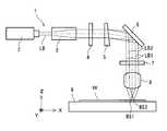
5 is a plan view showing a state of the beam spot irradiated to the work.
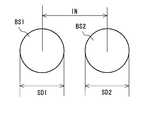
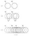
6A to 6C are plan views illustrating the scanning state of the beam spot.
7A is a cross-sectional view when the laser beam is irradiated onto the work. FIG. 7B is a cross-sectional view when the laser beam is moved from the state of FIG. 7A.
8 is a perspective view showing the main portion of the workpiece after moving the laser beam and irradiating the workpiece.
9 is a graph showing the relationship between the measurement result of the scribe depth and the defocus position in the example.
이하에 있어서는, 본 발명의 실시형태를 도 1 내지 도 8을 참조하면서 설명한다.EMBODIMENT OF THE INVENTION Below, embodiment of this invention is described, referring FIGS. 1-8.
본 발명을 설명함에 있어서, 우선 도 1을 참조하면서, 라인 형상의 스크라이브 홈(SL)이 형성된 워크(W)에 대해 설명한다.In describing the present invention, the work W in which the line-shaped scribe groove SL is formed will first be described with reference to FIG. 1.
워크(W)는 예를 들어 반도체 소자나 칩 저항기 등의 전자 부품을 위한 집합 기판이나 웨이퍼이다. 이 워크(W)는, 예를 들어 세라믹스, 실리콘 또는 사파이어 등의 경취 재료를 주재료로 한다. 이와 같은 워크(W)는 라인 형상의 스크라이브 홈(SL)에 의해 규정되는 개개의 영역이 개별의 반도체 소자나 칩 저항기 등의 전자 부품을 구성한다. 이 스크라이브 홈(SL)을 따라 워크(W)를 절단함으로써, 다수개의 전자 부품을 얻을 수 있다. 스크라이브 홈(SL)의 형성은 전자 부품의 종류에 따라 타이밍이 선택되는데, 예를 들어 전자 소자를 만들어 넣기 전, 전자 소자를 만들어 넣은 후, 또는 전자 소자의 일부를 만들어 넣은 후에 형성된다.The workpiece | work W is an assembly board | substrate or wafer for electronic components, such as a semiconductor element and a chip resistor, for example. This workpiece | work W has a hard material, such as ceramics, silicon, or sapphire, as a main material, for example. Each of the workpieces W defined by the line-shaped scribe groove SL constitutes an electronic component such as an individual semiconductor element or a chip resistor. By cutting the workpiece | work W along this scribe groove SL, many electronic components can be obtained. The timing of the scribe groove SL is selected according to the type of the electronic component. For example, the scribe groove SL is formed before the electronic component is made, after the electronic component is made or after a part of the electronic component is made.
도 2에 도시한 스크라이브 장치(1)는 레이저 광원(2), 빔 익스팬더(3), 1/2 파장판(4), 복굴절 소자(5), 반사판(6), 1/4 파장판(7), 집광 렌즈(8) 및 스테이지(9)를 구비하고 있다.The
레이저 광원(2)은, 일반적으로 워크(W)에 있어서의 광 흡수가 큰 파장의 레이저광(LB)을 출사하는 것이다. 본 실시형태에서는 레이저 광원(2)은 공간적으로 고정된 것으로 한다. 레이저 광원(2)으로서는, 다광자 흡수를 이용한 가공을 행하기 위해서, 워크(W)에 대해서 투명해지는 발진 파장을 가지는 레이저를 사용할 수 있다. 사용하는 레이저광(LB)은 편광이 직선 편광인 것이 일반적이지만, 원 편광 또는 랜덤 편광이어도 된다. 레이저광(LB)의 파장은 워크(W)의 광학 특성 및 필요로 하는 스크라이브 홈 폭에 맞추어 적외, 가시, 자외역 중에서 선택된다. 이와 같은 레이저 광원(2)으로서는, YAG 레이저(예를 들어 Nd : YAG 레이저)나 파이버 레이저 등의 고체 레이저 및 그 고조파를 사용할 수 있다.In general, the
또한, 레이저광(LB)의 발진 스펙트럼 폭이 넓은 경우에는, 복굴절 소자(5)에 의해 명확한 스포트로 분리할 수 없기 때문에, 스펙트럼 폭이 좁은 레이저인 것이 바람직하다.In addition, when the oscillation spectrum width of laser beam LB is large, since
빔 익스팬더(3)는 레이저 광원(2)으로부터 출사된 단일 광속의 레이저광(LB)의 빔 직경을 확장하기 위한 것이다. 레이저 광원(2)으로부터 출사된 레이저광(LB)은 이 빔 익스팬더(3)에 의해, 그 직경이 사용하는 집광 렌즈의 입사동 직경에 적합하도록 통상 2배 내지 10배로 확장된다. 빔 익스팬더(3)는 레이저광(LB)의 출사 빔 직경이 집광 렌즈의 입사동 직경에 대해서 충분히 큰 경우에는 불필요하다.The
1/2 파장판(4)은 레이저광(LB)이 직선 편광인 경우, 그 편광 방향을 광축 둘레에 회전시켜, 복굴절 소자(5)의 결정축과 편광 방향이 이루는 각도를 바꾸기 위한 것이다. 레이저광(LB)의 편광 방향과 복굴절 소자(5)의 결정축이 이루는 각도는 통상 45도로 설정되며, 이것에 의해 분리되는 레이저광(LB1, LB2)의 강도비는 1:1이 된다. 또 복굴절 소자(5)로서 도시한 예와 같이 웨지가 부착된 수정판을 사용하는 경우에는 복굴절 소자(5)의 결정축 및 웨지각 방향과 레이저광(LB)의 편광 방향이 이루는 각도를 제어함으로써, LB1과 LB2의 강도비를 제어할 수 있다. 레이저광(LB)이 원 편광이나 랜덤 편광인 경우에는 이와 같은 제어는 불가능하기 때문에 1/2 파장판은 불필요하다.When the laser light LB is linearly polarized light, the 1/2
복굴절 소자(5)는 입사한 단일 광속의 레이저광(LB)을 진행 방향이 상이한 복수 광속의 레이저광(LB1, LB2)으로 분리하기 위한 것이다. 이 복굴절 소자(5)는 레이저광(LB)의 광전장 벡터를 상광 성분과 이상광 성분으로 분리한다. 이 상광 성분과 이상광 성분의 강도비는 입사하는 레이저광의 편광 방향(광전장 벡터의 방향)과 복굴절 소자(5)의 결정축이 이루는 각도에 의해 결정된다. 또한 복굴절 소자(5)에는 웨지각이 붙여져 있기 때문에, 상광에 대한 굴절률과 이상광에 대한 굴절률이 상이한 점에서 프리즘으로서 기능한다. 이와 같이 복굴절 소자(5)를 투과한 레이저광(LB)은 편광 방향이 서로 직교하는 상광과 이상광으로 분리되고, 웨지각 방향으로 상이한 출사 각도를 가지고 진행하는 2개의 레이저광(LB1, LB2)으로 분리된다. 레이저광(LB1, LB2)의 분리 방향을 스크라이브 방향에 일치시키기 위해서, 복굴절 소자(5)를 광축 둘레에 회전시키는 기구가 있지만, 도 3에 있어서는 생략되어 있다.The
또 이와 같은 복굴절 소자(5)의 웨지각에 의해, 복굴절 소자(5)를 투과한 레이저광의 진행 방향이 입사 레이저광축과 상이하기 때문에, 이것을 보정하기 위한 웨지 프리즘을 광로 중에 삽입해도 된다.Moreover, since the advancing direction of the laser beam which permeate | transmitted the
복굴절 소자(5)로서 도시한 예와 같이 웨지가 부착된 수정판을 사용하는 경우, 이 수정판에 있어서는, 웨지 각도(수정판에 있어서의 광 입사면(50)과 광 출사면(51)의 교차 각도)(θ), 레이저광(LB)의 파장 및 집광 렌즈(8)의 촛점 거리에 따라 워크(W)에 형성되는 빔 스포트(BS1, BS2)의 이간 거리(중심간 거리)(IN)를 규정할 수 있다. 예를 들어 레이저광(LB)의 파장을 1.064μm, 집광 렌즈(8)의 촛점 거리를 100mm로 한 경우, 이간 거리(IN)를 60μm로 설정하기 위해서는, 웨지 각도(θ)는 약 2도로 설정된다.When using a quartz plate with wedges as in the example shown as the
복굴절 소자(5)로서는, 도시한 웨지가 부착된 수정판 이외에 복상 프리즘을 사용할 수도 있다. 복상 프리즘은 분리한 상광과 이상광의 일방을 차단하지 않고 각각의 방향으로 나누어서 송출하도록 한 프리즘이다. 이와 같은 복상 프리즘으로서는 예를 들어 월라스톤 프리즘을 들 수 있다.As the
도 2에 도시한 반사판(6)은 복굴절 소자(5)로부터 출사된 복수 광속의 레이저광(LB1, LB2)의 광로를 바꾸어 집광 렌즈(8)에 이끌기 위한 것이다. 반사판(6)으로서는 전반사 미러 등 공지된 것을 사용할 수 있다.The reflecting
1/4 파장판(7)은 복수 광속의 레이저광(LB1, LB2)의 각각을 직선 편광으로부터 원 편광으로 바꾸기 위한 것이다. 또한, 이 1/4 파장판(7)은 필요에 따라서 복굴절 소자(5)와 집광 렌즈(8) 사이에 배치된다. 1/4 파장판(7)의 결정축이 레이저광(LB1, LB2)의 편광 방향에 대해서 모두 45도의 각도를 이루도록 광로 중에 삽입함으로써, 레이저광(LB1, LB2)의 각각을 원 편광으로 할 수 있다. 일반적으로 편광 방향과 스크라이브 방향이 이루는 각도에 의해 스크라이브 특성이 변화하기 때문에, 직선 편광을 원 편광으로 변환하여 편광의 영향을 받기 어려운 스크라이브 가공을 실현할 수 있다. 도 3에 있어서는 도시하지 않지만, 곡선 형상의 스크라이브를 행하는 경우 등, 레이저광(LB1, LB2)의 분리 방향(편광 방향)을 연속적으로 변화시킬 필요가 있는 경우에는, 그것에 맞추어 1/4 파장판(7)을 회전시키는 기구가 필요하다.The
도 2의 집광 렌즈(8)는, 예를 들어 도 4나 도 5에 도시한 바와 같이 복수 광속의 레이저광(LB1, LB2)의 각각을 집광하고, 워크(W) 상에 복수의 빔 스포트(BS1, BS2)를 형성하기 위한 것이다. 집광 렌즈(8)의 종류로서는, 레이저광(LB1, LB2)을 목적으로 하는 스포트 직경(SD1, SD2)으로 집속할 수 있는 것이면 된다. 워크(W) 상에 형성되는 빔 스포트(BS1, BS2)의 직경(SD1, SD2)은 예를 들어 1μm 내지 200μm가 된다. 이와 같은 스포트 직경(SD1, SD2)의 빔 스포트(BS1, BS2)를 워크(W) 상에 형성하는 경우에는 집광 렌즈(8)로서는, 예를 들어 촛점 거리가 2mm 내지 500mm로 설정된 것이 사용된다. 또한, 상기 스포트 직경(SD1, SD2)에는 집광 렌즈(8)에 입사하는 레이저광(LB1, LB2)의 빔 직경 및 그 파장이 관계되어 있다.The condensing
스테이지(9)는 워크(W)를 지지하기 위한 것이며, 예를 들어 X방향, Y방향 및 Z방향의 3방향으로 이동 가능하게 되어 있다. 본 실시형태에서는 레이저 광원(2)(레이저광(LB1, LB2))이 공간적으로 고정되어 있기 때문에, 스테이지(9)의 이동에 의해 워크(W)를 상대적으로 이동시키고, 그 결과, 레이저광(LB1, LB2)이 이동된다. 또한, 워크(W)를 공간적으로 고정하고, 레이저광(LB1, LB2)을 상대적으로 이동시키는 갈바노미터 스캐너 등의 수단을 사용할 수 있다. 이 스테이지(9)의 이동 방향을 제어함으로써, 빔 스포트(BS1, BS2)의 이동 궤적을 제어할 수 있다. 또 스테이지(9)의 이동 속도를 제어함으로써, 빔 스포트(BS1, BS2)의 이동 속도(스크라이브 속도)(SP)를 제어할 수 있다.The
도 2에 있어서, 빔 스포트(BS1, BS2)는 스크라이브 방향과 평행하게 분리할 필요가 있기 때문에, 스테이지(9)의 이동 방향에 맞추어, 복굴절 소자(5)를 광축 둘레에 회전시킨다. 구체적으로는, 예를 들어 X방향으로 스크라이브하는 경우에는 X방향으로 빔 스포트(BS1, BS2)를 분리시킬 필요가 있기 때문에, 복굴절 소자(5)의 웨지각 방향이 XZ 평면 내에 포함되도록 복굴절 소자(5)를 회전하여 조정을 행한다. 한편, Y방향으로 스크라이브하는 경우에는 Y방향으로 빔 스포트(BS1, BS2)를 분리시킬 필요가 있기 때문에, 추가로 복굴절 소자(5)를 광축 둘레에 90도 회전시켜, 복굴절 소자(5)의 웨지각 방향이 XY 평면 내에 포함되도록 조정한다.In FIG. 2, since the beam spots BS1 and BS2 need to be separated in parallel with the scribe direction, the
이와 같은 웨지각의 회전 방향의 조정에 의해, 보다 가공 대상물에 적합한 스크라이브 방법을 선택하는 것이 가능해진다.By adjusting the rotation direction of such wedge angle, it becomes possible to select the scribing method more suitable for a process object.
다음에 스크라이브 장치(1)를 사용한 스크라이브 홈(SL)의 형성 방법에 대해 설명한다.Next, a method of forming the scribe groove SL using the
스크라이브 장치(1)를 사용하여 스크라이브 홈(SL)을 형성하는 경우에는, 레이저 광원(2)으로부터 레이저광(LB)을 출사시키면서, 워크(W)에 대해서 빔 스포트(BM1, BM2)를 상대적으로 스크라이브 방향(X방향 또는 Y방향)으로 이동시킨다.When the scribe groove SL is formed using the
레이저 광원(2)으로부터 출사되는 레이저광(LB)은 직선 편광이며, 그 파장이 기본파, SHG(제2 고조파), THG(제3 고조파), 또는 FHG(제4 고조파)이다. 이와 같은 레이저광(LB)은 워크(W)의 표면에서의 평균 출력이 예를 들어 0.1W 내지 200W가 되도록 CW(연속 발진)광 또는 주파수가 100Hz 내지 1GHz의 펄스로서 출사된다. Q 스위치 레이저의 경우, 그 펄스폭이 워크(W)의 재료 특성에 적합한 값을 가지는 레이저가 선정된다.The laser light LB emitted from the
워크(W)에 대한 빔 스포트(BS1, BS2)의 상대적인 이동은 워크(W)를 이동시키는 방법, 집광 렌즈(8)를 이동시키는 방법, 또는 레이저광(LB1, LB2)을 갈바노미터 스캐너 등의 수단을 사용하는 방법에 의해 행할 수 있다. 또한, 이와 같은 BS1, BS2의 상대적인 이동은 통상은 스테이지(9)의 이동에 의해 행해진다. 워크(W)에 대한 빔 스포트(BS1, BS2)의 상대적인 이동 속도(스크라이브 속도)(SP)는 예를 들어 1mm/sec 내지 1000mm/sec로 설정된다.The relative movement of the beam spots BS1 and BS2 relative to the workpiece W may be performed by moving the workpiece W, moving the
레이저 광원(2)으로부터 출사된 단일 광속의 레이저광(LB)은 빔 익스팬더(3)에 의해 집광 렌즈에 적합한 빔 직경이 되도록 확대된 후에 1/2 파장판(4)을 투과한다.The laser beam LB of a single light beam emitted from the
1/2 파장판(4)을 투과한 단일 광속의 레이저광(LB)은 직선 편광인 경우, 레이저광(LB)의 편광 방향이 소정의 각도로 회전하고, 복굴절 소자(5)를 투과한다. 레이저광(LB)은 복굴절 소자(5)를 투과할 때에 진행 방향이 상이한 복수 광속의 레이저광(LB1, LB2)으로 분리된다. 또한, 복굴절 소자(5)로서 웨지가 부착된 수정판을 사용하는 경우, 복수 광속의 레이저광(LB1, LB2)의 분리 각도는 웨지각과 레이저 파장에 의해 규정할 수 있다. 또 복수 광속의 레이저광(LB1, LB2)의 분리 각도와 집광 렌즈(8)의 촛점 거리를 조정함으로써 워크(W) 상에 형성되는 빔 스포트(BS1, BS2)의 이간 거리(IN)를 규정할 수 있다.When the laser beam LB of the single light beam transmitted through the 1/2
복굴절 소자(5)를 투과한 복수 광속의 레이저광(LB1, LB2)은 반사판(6)에 있어서 광로가 바뀐 후에 1/4 파장판(7)을 투과한다. 1/4 파장판(7)을 투과한 복수 광속의 레이저광(LB1, LB2)은 직선 편광으로부터 원 편광으로 변환된 후에 집광 렌즈(8)에 입사된다. 또한, 1/4 파장판(7)은 직선 편광을 워크(W)에 조사할 때에 레이저 가공의 특성을 바꾸는 것이며, 이것을 생략할 수도 있다.The laser beams LB1 and LB2 of the plurality of light beams passing through the
집광 렌즈(8)에 입사한 복수 광속의 레이저광(LB1, LB2)은 각각 집속되고, 워크(W) 상에 빔 스포트(BS1, BS2)를 형성한다. 빔 스포트(BS1, BS2)의 스포트 직경(SD1, SD2)은 집광 렌즈(8)에 입사하는 레이저광(LB1, LB2)의 빔 직경, 집광 렌즈(8)의 촛점 거리에 의해 결정된다. 촛점 위치 또는 빔 웨이스트 위치를 워크(W)의 표면에 형성할 것인가, 워크(W)의 내부에 형성할 것인가에 의해, 워크(W) 표면 상의 스포트 직경(SD1, SD2)을 제어하는 것이 가능하다.The laser beams LB1 and LB2 of the plurality of light beams incident on the
도 6(a) 및 도 7(a)에는 1쇼트의 레이저광(LB)을 출사했을 때의 워크(W)의 상태를 도시했다. 워크(W)에는 한 번에 2개의 레이저광(LB1, LB2)이 조사되기 때문에, 2개의 구멍(H1, H2)이 동시에 형성된다.6 (a) and 7 (a) show the state of the workpiece W when one shot of the laser beam LB is emitted. Since the laser beam LB1 and LB2 are irradiated to the workpiece | work W at once, two holes H1 and H2 are formed simultaneously.
도 6(b) 및 도 7(b)에 도시한 바와 같이, 워크(W)를 소정의 스크라이브 속도(SP)(예를 들어 1mm/sec 내지 1000mm/sec)로 이동시키면서, 레이저 광원(2)으로부터 2쇼트째의 레이저광(LB)을 출사시킨 경우, 각각의 레이저광(LB1, LB2)에 관하여 앞서 형성된 구멍(H1, H2)에 연속하도록 새로운 구멍(H1, H2)이 형성된다. 이와 같은 레이저광(LB)의 펄스 발진을 반복해서 행하면서 빔 스포트(BS1, BS2)를 이동시킴으로써, 도 6(c)에 도시한 빔 스포트(BS1, BS2)의 궤적이 스크라이브 방향으로 이어진다. 그 결과, 도 8에 도시한 바와 같이, 워크(W)에는 스크라이브 방향을 따른 홈(L)이 형성된다. 구체적으로는, 빔 스포트(BS1, BS2)를 목적으로 하는 궤적을 돌도록 스테이지(9)를 X방향 또는 Y방향으로 이동시키고, 스크라이브 방향을 X방향과 Y방향 사이에서 전환할 때에 복굴절 소자(5)나 1/4 파장판(7)을 회전시킴으로써, 도 1에 도시한 바와 같이 워크(W)에 목적으로 하는 스크라이브 홈(SL)을 형성할 수 있다.As shown in Fig. 6 (b) and Fig. 7 (b), the
이와 같이, 스크라이브 장치(1)에서는, 앞서 형성된 구멍에 빔 스포트(BS1, BS2)를 위치 맞춤하여 레이저광(LB1, LB2)을 조사할 필요가 없다. 즉, 이 스크라이브 장치(1)에 의하면, 복잡한 제어가 필요없이, 빔 스포트(BS1, BS2)의 이동의 제어를 용이하게 행할 수 있다. 또 단일 광속의 레이저광(LB)을 복수 광속의 빔 스포트(LB1, LB2)로 분리하기 위해서는, 예를 들어 복굴절 소자(5)로서 웨지가 부착된 수정판을 배치하기만 하면 되는 점에서, 레이저광(LB)을 분리하는 구성을 채용하는 경우에도 레이저 스크라이브 장치(1)의 구성이 그다지 복잡화되지도 않는다.In this way, in the
스크라이브 장치(1)는 단일 광속의 레이저광(LB)으로부터 형성되는 복수의 빔 스포트(BS1, BS2)를 워크(W)에 조사하고, 워크(W)에 스크라이브 홈(SL)을 형성하는 것이다. 이와 같은 수법에 의하면, 후술하는 실시예의 결과로부터도 알 수 있는 바와 같이, 단일 광속의 레이저광(LB)으로부터 복수 광속의 빔 스포트(BS1, BS2)를 형성하여 워크(W)에 레이저광(LB1, LB2)이 조사되기 때문에, 레이저광(LB)의 에너지를 유효하게 이용하여 라인 형상의 스크라이브 홈(SL)을 효율적으로 형성할 수 있다. 예를 들어, 단일 광속의 레이저광(LB)을 복수 광속의 레이저광(LB1, LB2)으로 분리하여 워크(W)에 조사한 경우, 단일 광속의 레이저광(LB)을 분리하지 않고 워크(W)에 조사하는 경우에 비해, 보다 깊은 스크라이브 홈(SL)을 형성할 수 있고, 또는 목적으로 하는 스크라이브 홈(SL)을 형성하는 경우에 스크라이브 속도(SP)를 크게 설정할 수 있다. 이와 같이, 단일 광속의 레이저광(LB)을 복수 광속의 레이저광(LB1, LB2)으로 분리하여 워크(W)에 조사한 경우, 동일한 레이저 파워를 가지는 단일 광속의 레이저광(LB)을 분리하지 않고 이용하는 경우에 비해 보다 깊은 스크라이브 홈(SL)을 형성할 수 있고, 또한 주사 속도(SP)도 크게 설정할 수 있다.The
이와 같은 효과가 얻어지는 것은 다른 요인도 생각되지만, 주로 이하의 이유에 의해, 레이저광(LB)의 에너지를 유효하게 이용하여 효율적으로 스크라이브 홈(SL)을 형성할 수 있기 때문이라고 생각된다.Although such an effect is also considered, other factors are considered, but it is mainly considered that the scribe groove SL can be efficiently formed using the energy of the laser beam LB mainly for the following reasons.
제1 이유는 플라즈마에 의한 에너지(광자)의 흡수에 기인하는 것이다. 즉, 워크(W)에 레이저광(LB1, LB2)으로서 펄스 형상의 레이저광을 조사하면, 각 조사 펄스의 초기 단계에서 워크(W)의 재료가 용융·기화하여 플라즈마가 생성되고, 그 후의 펄스 레이저광이 플라즈마에 의해 흡수되어 버린다. 그 때문에 이 플라즈마에 의해 스크라이브 홈의 안까지 도달하는 레이저의 광량이 줄어들고, 그 결과, 깊은 스크라이브 홈의 형성이 어려워진다.The first reason is due to absorption of energy (photons) by the plasma. That is, when the laser beam of pulse shape is irradiated to the workpiece | work W as laser beam LB1 and LB2, the material of the workpiece | work W will melt | evaporate and vaporize in the initial stage of each irradiation pulse, and a plasma will generate | occur | produce after that. The laser light is absorbed by the plasma. As a result, the amount of laser light reaching the inside of the scribe groove is reduced by this plasma, and as a result, the formation of the deep scribe groove becomes difficult.
한편, 복수의 빔 스포트(BS1, BS2)를 스크라이브 방향으로 분리하여 형성한 경우, 스크라이브 홈(SL)의 형성시에는 스크라이브 방향으로 선행하는 빔 스포트(BS2)를 빔 스포트(BS1)가 쫓아가는 형태가 된다. 그 때문에, 빔 스포트(BS2)에 의해 생성된 플라즈마가 소멸한 후에, 앞선 레이저광(LB2)의 조사 위치(빔 스포트(BS2))의 근방에 빔 스포트(BS1)를 조사하는 것이 가능해진다. 즉, 레이저광(LB1)을 조사하는 시점에서, 이미 플라즈마가 감소한 영역 근방에 레이저광(LB1)을 조사하는 것이 가능해진다. 그 결과, 플라즈마에 의한 흡수(에너지 로스)를 피하여, 조사 에너지를 유효하게 이용할 수 있기 때문에, 스크라이브 홈(SL)의 깊이를 크게 할 수 있다고 생각된다.On the other hand, when the plurality of beam spots BS1 and BS2 are formed separately in the scribe direction, the beam spot BS1 follows the beam spot BS2 leading in the scribe direction when the scribe groove SL is formed. Becomes Therefore, after the plasma generated by the beam spot BS2 is extinguished, the beam spot BS1 can be irradiated to the vicinity of the irradiation position (beam spot BS2) of the preceding laser light LB2. That is, at the time of irradiating the laser beam LB1, it becomes possible to irradiate the laser beam LB1 in the vicinity of the region where the plasma has already decreased. As a result, it is considered that the irradiation energy can be effectively used to avoid absorption by the plasma (energy loss), so that the depth of the scribe groove SL can be increased.
제2 이유는 레이저광(LB1)의 스크라이브 홈 내에서의 다중 반사와 흡수에 기인하는 것이다. 상기 서술한 바와 같이, 가공 영역에서 발생한 플라즈마에 의한 레이저광의 흡수가 경감되면, 후속의 레이저 빔은 초기에 형성된 스크라이브 가공 홈의 바닥까지 진행해 가는 것이 가능해진다. 스크라이브 홈에 진행한 후속의 레이저광은 홈 측면에서 반사를 반복하면서 홈의 안까지 진행하고, 그 동안에 워크(W)에 흡수되어 간다. 평면 형상의 워크면에 레이저광(LB1)을 조사하는 경우에 비해, 미리 구멍(H2)이 형성되어 있는 위치에 레이저광(LB1)을 조사하는 쪽이 홈 측면에 의한 다중 반사와 흡수의 혜택을 받기 쉽고, 레이저광(LB1)의 에너지를 유효하게 이용할 수 있다. 그 결과, 레이저광(LB1)의 조사 위치(빔 스포트(BS1))에 있어서 조사 에너지를 유효하게 이용할 수 있기 때문에, 스크라이브 홈(SL)의 깊이를 크게 할 수 있다고 생각된다. 또 레이저광(LB2)의 조사에 의해, 후속의 LB1이 조사되는 시점에서는, 워크(W)의 조사 부위의 온도가 고온인 상태를 유지하고 있다. 일반적으로 재료의 반사율은 고온에서는 저하되기 때문에, 레이저광(LB1)의 흡수는 보다 효율적으로 행해지게 된다.The second reason is due to multiple reflection and absorption in the scribe groove of the laser light LB1. As mentioned above, when absorption of the laser beam by the plasma which generate | occur | produced in the process area | region is reduced, it becomes possible for a subsequent laser beam to advance to the bottom of the scribed groove formed initially. Subsequent laser light traveling to the scribe groove proceeds to the inside of the groove while repeating the reflection on the groove side, while being absorbed by the work W. Compared to the case where the laser beam LB1 is irradiated to the planar work surface, the irradiation of the laser beam LB1 to the position where the hole H2 is formed in advance provides the benefit of multiple reflection and absorption by the groove side. It is easy to receive, and the energy of laser beam LB1 can be used effectively. As a result, since irradiation energy can be used effectively at the irradiation position (beam spot BS1) of the laser beam LB1, it is thought that the depth of the scribe groove SL can be enlarged. Moreover, when the subsequent LB1 is irradiated by irradiation of the laser beam LB2, the temperature of the irradiation site of the workpiece | work W is maintaining the high temperature. Generally, since the reflectance of a material falls at high temperature, absorption of the laser beam LB1 is performed more efficiently.
(실시예)(Example)
레이저 광원으로부터 출사된 레이저광을 분리하여 복수의 빔 스포트를 형성 가능한 레이저 스크라이브 장치를 사용하여 워크에 스크라이브 홈을 형성한 경우에, 디포커스 위치와 홈의 깊이의 관계를 검토했다.When the scribe groove was formed in the workpiece | work using the laser scribe device which can isolate | separate the laser beam radiate | emitted from the laser light source, and can form a several beam spot, the relationship between the defocus position and the depth of the groove was examined.
레이저 스크라이브 장치로서는 도 2에 도시한 레이저 스크라이브 장치에 있어서 1/4 파장판을 생략한 구성의 것을 사용했다.As the laser scribe device, one having a configuration in which a quarter wave plate was omitted in the laser scribe device shown in FIG. 2 was used.
레이저 광원으로서는 Nd : YAG 레이저(파장 1064nm, 출력 10W)를 사용했다. 레이저광의 출력 특성은 표 1에 나타나 있는 바와 같이 설정했다.Nd: YAG laser (wavelength 1064 nm, output 10W) was used as a laser light source. The output characteristics of the laser beam were set as shown in Table 1.
복굴절 소자로서는 웨지각이 2°인 수정판을 사용했다.As a birefringent element, a quartz plate having a wedge angle of 2 ° was used.
집광 렌즈로서는 촛점 거리(f)가 50mm인 렌즈를 사용했다.As the condenser lens, a lens having a focal length f of 50 mm was used.
워크로서는 두께가 0.28mm인 알루미나 세라믹스를 사용했다.As the work, alumina ceramics having a thickness of 0.28 mm were used.
스크라이브 속도(빔 스포트의 이동 속도)(SP)는 50mm/sec로 설정했다.The scribe speed (speed of movement of the beam spot) SP was set to 50 mm / sec.
스크라이브 홈의 깊이는 촛점 위치와, 이 촛점 위치로부터의 어긋남량(디포커스 거리)이 상이한 각 개소(10μm 피치)에 있어서 측정했다. 동일한 디포커스 거리에서의 깊이의 측정은 기본적으로 3개소에 대해서 행했다. 스크라이브 깊이는 스크라이브 홈의 단면을 스케일이 부착된 스테이지를 가지는 측정 현미경(니콘제)을 사용하여 관찰함과 아울러, 스케일의 메모리를 판독함으로써 측정했다.The depth of the scribe groove | channel was measured in each location (10 micrometer pitch) where a focal position and a shift amount (defocus distance) from this focal position differ. The measurement of the depth in the same defocus distance was performed about three places basically. The scribe depth was measured by observing the cross section of the scribe groove using a measuring microscope (manufactured by Nikon) having a stage with a scale, and reading the memory of the scale.
동일한 디포커스 거리에서의 깊이의 측정 결과의 평균값을 디포커스 거리(상대 위치)와 스크라이브 깊이의 관계로서 도 9에 도시했다. 도 9의 그래프에 있어서는, 실시예의 레이저 스크라이브 장치를 사용한 경우의 측정 결과(플롯점)와 그들의 근사 곡선을 실선으로 도시했다.The average value of the measurement result of the depth at the same defocus distance is shown in FIG. 9 as a relationship between the defocus distance (relative position) and the scribe depth. In the graph of FIG. 9, the measurement result (plot point) and the approximation curve in the case of using the laser scribe apparatus of an Example were shown by the solid line.
(비교예)(Comparative Example)
한편, 비교예로서 레이저 광원으로부터 출사된 레이저광을 분리하지 않고 단일의 빔 스포트에 의해 스크라이브 홈을 형성한 종래 방식에 의한 경우를 측정했다. 표 1에 나타나 있는 바와 같이, 비교예에서는 실시예의 레이저 스크라이브 장치에 있어서, 복굴절 소자 및 1/2 파장판을 생략한 스크라이브 장치를 사용하여 워크에 스크라이브 홈을 형성했다. 도 9에 동일한 디포커스 거리에 있어서의 측정 평균값과 그들의 근사 곡선을 점선으로 도시했다.On the other hand, the comparative example measured the case by the conventional system which formed the scribe groove by the single beam spot, without isolate | separating the laser beam radiate | emitted from the laser light source. As shown in Table 1, in the comparative example, in the laser scribing apparatus of an Example, the scribe groove | channel was formed in the workpiece | work using the scribing apparatus which omitted the birefringent element and the 1/2 wave plate. In Fig. 9, measured average values and their approximation curves at the same defocus distance are shown by dotted lines.

도 9로부터 실시예의 레이저 스크라이브 장치에 의해 스크라이브 홈을 형성한 경우와 비교예의 레이저 스크라이브 장치에 의해 스크라이브 홈을 형성했을 때를 비교한 경우, 촛점 위치 및 디포커스 위치의 각각에 있어서, 실시예 쪽이 스크라이브 홈의 깊이가 커져 있었다.When comparing the case where the scribe groove was formed by the laser scribe device of the embodiment from FIG. 9 and the case where the scribe groove was formed by the laser scribe device of the comparative example, the embodiment side in each of the focus position and the defocus position was compared. The depth of the scribe groove was larger.
따라서, 실시예의 레이저 스크라이브 장치를 사용하여 단일 광속의 레이저광을 분리하여 복수의 빔 스포트를 워크에 조사하여 스크라이브 홈을 형성한 경우, 동일한 레이저 파워의 단일 광속의 레이저광을 단일의 빔 스포트를 형성하여 워크에 스크라이브 홈을 형성하는 경우에 비해, 빔 스포트의 주사 속도(스크라이브 속도)가 동일해도 보다 깊은 스크라이브 홈을 형성할 수 있는 것이 확인되었다.Therefore, when the laser scribe device of the embodiment is used to separate a laser beam of a single beam and irradiate a plurality of beam spots to a work to form a scribe groove, the laser beam of a single beam of the same laser power forms a single beam spot. As compared with the case of forming a scribe groove in the work, it was confirmed that a deeper scribe groove can be formed even if the scanning speed (scribe speed) of the beam spot is the same.
1…레이저 스크라이브 장치2…레이저 광원
3…빔 익스팬더4…1/2 파장판
5…복굴절 소자6…반사판
7…1/4 파장판8…집광 렌즈
9…스테이지50…광 입사면
51…광 출사면BM1, BM2…빔 스포트
f…촛점 거리H1, H2…구멍
IN…이간 거리LB…레이저광
LB1, LB2…레이저광SD1, SD2…스포트 직경
SL…스크라이브 홈SP…스크라이브 속도(주사 속도)
W…워크θ…웨지 각도One…
3 ...
5...
7 ...
9 ...
51 ... Light exit surface BM1, BM2... Beam spot
f… Focal length H1, H2... hole
IN… Distance LB… Laser light
LB1, LB2... Laser light SD1, SD2... Spot diameter
SL… Scribe home SP… Scribe Speed (Scan Speed)
W… Work? Wedge angle
Claims (18)
Translated fromKorean상기 복수의 빔 스포트는 단일 광속(luminous flux)의 레이저광으로부터 얻어지는 것이고,
상기 복수의 빔 스포트는 상기 단일 광속의 레이저광을 상이한 각도를 가지고 진행하는 복수 광속의 레이저광으로 분리함과 아울러, 상기 복수 광속의 레이저광의 각각을 집속하여 얻어지는 것을 특징으로 하는, 레이저 스크라이브 방법.A laser scribing method for forming a plurality of beam spots arranged side by side in a scribe direction on a workpiece in a state separated from each other, and moving the plurality of beam spots in the scribe direction to form a line-shaped scribe groove in the workpiece. ,
The plurality of beam spots are obtained from laser light of a single luminous flux,
And the plurality of beam spots are obtained by separating the laser beam of the single luminous flux into laser beams of a plurality of luminous fluxes traveling at different angles and focusing each of the laser beams of the plurality of luminous fluxes.
상기 단일 광속의 레이저광은 복굴절 소자에 의해 상기 복수 광속의 레이저광으로 분리되는 것을 특징으로 하는, 레이저 스크라이브 방법.The method of claim 1,
And the laser beam of the single light beam is separated into the laser light of the plurality of light beams by a birefringent element.
상기 복굴절 소자는 웨지가 부착된 수정판인 것을 특징으로 하는, 레이저 스크라이브 방법.The method of claim 2,
The birefringence element is a laser scribe method, characterized in that the wedge attached quartz plate.
상기 복굴절 소자는 복상 프리즘인 것을 특징으로 하는, 레이저 스크라이브 방법.The method of claim 2,
And said birefringent element is a biaxial prism.
상기 단일 광속의 레이저광은 상기 복굴절 소자에 의해 서로 편광 방향이 직교하는 정상광(ordinary ray) 성분과 이상광(extraordinary ray)성분으로 분리되는 것을 특징으로 하는, 레이저 스크라이브 방법.The method of claim 2,
The laser beam scribing method of claim 1, wherein the laser beam of the single light beam is separated into an ordinary ray component and an extraordinary ray component in which polarization directions are orthogonal to each other by the birefringent element.
상기 단일 광속의 레이저광의 분리 방향은 상기 복수의 레이저 스포트의 이동 방향으로 분리되는 것을 특징으로 하는, 레이저 스크라이브 방법.The method of claim 2,
The separation direction of the laser beam of the single light beam is separated in the moving direction of the plurality of laser spots, the laser scribe method.
단일 광속의 레이저광을 출사하기 위한 레이저 광원과,
상기 단일 광속의 레이저광을 스크라이브 방향을 따라 상이한 각도를 가지고 진행하는 복수 광속의 레이저광으로 분리하기 위한 분리 수단과,
상기 복수 광속의 레이저광의 각각을 집광하기 위한 집광 수단과,
상기 복수 광속의 레이저광과 워크를 상대 이동시키는 광주사 수단,
을 구비한 것을 특징으로 하는, 레이저 스크라이브 장치.An apparatus for forming a line-shaped scribe groove in a workpiece,
A laser light source for emitting a single beam of laser light,
Separating means for separating the laser beam of the single beam into laser beams of a plurality of beams traveling at different angles along the scribe direction;
Condensing means for condensing each of the plurality of laser beams;
Optical scanning means for relatively moving the laser light of the plurality of beams and the workpiece,
Laser scribe device, characterized in that it comprises a.
상기 분리 수단은 복굴절 소자인 것을 특징으로 하는 레이저 스크라이브 장치.The method of claim 8,
And said separating means is a birefringent element.
상기 복굴절 소자는 웨지가 부착된 수정판인 것을 특징으로 하는 레이저 스크라이브 장치.The method of claim 9,
The birefringent element is a laser scribe device, characterized in that the wedge attached quartz plate.
상기 복굴절 소자는 복상 프리즘인 것을 특징으로 하는 레이저 스크라이브 장치.The method of claim 9,
And said birefringent element is a biaxial prism.
상기 분리 수단을 광축 둘레에 회전시키는 기구를 더 구비하고 있는 것을 특징으로 하는 레이저 스크라이브 장치.The method of claim 8,
And a mechanism for rotating the separating means around the optical axis.
상기 레이저 광원은 직선 편광의 레이저광을 출사 가능한 것이며,
상기 레이저광에 대해 편광 방향을 광축에 대해서 회전시키기 위한 1/2 파장판을 더 구비하고 있는 것을 특징으로 하는 레이저 스크라이브 장치.The method of claim 8,
The laser light source is capable of emitting laser light of linearly polarized light,
And a half wave plate for rotating the polarization direction with respect to the optical axis with respect to the laser beam.
상기 복수 광속의 레이저광의 각각을 직선 편광으로부터 원 편광으로 바꾸기 위한 1/4 파장판을 더 구비하고 있는 것을 특징으로 하는 레이저 스크라이브 장치.The method of claim 13,
And a quarter wave plate for changing each of the plurality of laser beams from linearly polarized light to circularly polarized light.
상기 1/4 파장판을 광축 둘레에 회전시키는 기구를 더 구비하고 있는 것을 특징으로 하는 레이저 스크라이브 장치.The method of claim 14,
And a mechanism for rotating said quarter wave plate about an optical axis.
상기 레이저 광원은 원 편광 또는 랜덤 편광의 레이저광을 출사 가능한 것인 것을 특징으로 하는 레이저 스크라이브 장치.The method of claim 8,
The laser light source is a laser scribe device, characterized in that the laser light of circularly or randomly polarized light can be emitted.
상기 집광 수단은 상기 복수 광속의 레이저광의 각각에 있어서의 빔 스포트가 상기 워크에 있어서 서로 분리된 상태에서 형성되도록 선정된 촛점 거리를 가지는 것을 특징으로 하는 레이저 스크라이브 장치.The method of claim 8,
And said condensing means has a focal length selected so that beam spots in each of said plurality of luminous fluxes are separated from each other in said workpiece.
Priority Applications (1)
| Application Number | Priority Date | Filing Date | Title |
|---|---|---|---|
| KR1020100008305AKR101098259B1 (en) | 2010-01-29 | 2010-01-29 | Laser scribe method and apparatus |
Applications Claiming Priority (1)
| Application Number | Priority Date | Filing Date | Title |
|---|---|---|---|
| KR1020100008305AKR101098259B1 (en) | 2010-01-29 | 2010-01-29 | Laser scribe method and apparatus |
Publications (2)
| Publication Number | Publication Date |
|---|---|
| KR20110088685A KR20110088685A (en) | 2011-08-04 |
| KR101098259B1true KR101098259B1 (en) | 2011-12-23 |
Family
ID=44927101
Family Applications (1)
| Application Number | Title | Priority Date | Filing Date |
|---|---|---|---|
| KR1020100008305AActiveKR101098259B1 (en) | 2010-01-29 | 2010-01-29 | Laser scribe method and apparatus |
Country Status (1)
| Country | Link |
|---|---|
| KR (1) | KR101098259B1 (en) |
Citations (1)
| Publication number | Priority date | Publication date | Assignee | Title |
|---|---|---|---|---|
| JPS6221207A (en)* | 1985-07-19 | 1987-01-29 | Fujitsu Ltd | Manufacturing method of semiconductor device |
- 2010
- 2010-01-29KRKR1020100008305Apatent/KR101098259B1/enactiveActive
Patent Citations (1)
| Publication number | Priority date | Publication date | Assignee | Title |
|---|---|---|---|---|
| JPS6221207A (en)* | 1985-07-19 | 1987-01-29 | Fujitsu Ltd | Manufacturing method of semiconductor device |
Also Published As
| Publication number | Publication date |
|---|---|
| KR20110088685A (en) | 2011-08-04 |
Similar Documents
| Publication | Publication Date | Title |
|---|---|---|
| JP5536319B2 (en) | Laser scribing method and apparatus | |
| KR101167242B1 (en) | Laser irradiation device and laser processing method | |
| JP5670647B2 (en) | Processing object cutting method | |
| JP4651731B2 (en) | Laser scribing method | |
| JP5379384B2 (en) | Laser processing method and apparatus for transparent substrate | |
| KR101891341B1 (en) | Laminated-substrate processing method and processing apparatus | |
| TWI419756B (en) | Substrate processing device and substrate processing method | |
| KR101426598B1 (en) | Laser dicing method | |
| JP6551275B2 (en) | Laser processing apparatus, three-dimensional modeling apparatus, and laser processing method | |
| US8450638B2 (en) | Laser scribing method and apparatus | |
| KR101425492B1 (en) | Laser machining apparatus and method thereof | |
| CN104907691A (en) | Laser processing apparatus and laser processing method | |
| JP5293791B2 (en) | Laser processing apparatus and processing method of workpiece using laser processing apparatus | |
| CN102139484A (en) | Laser scribing method and device | |
| WO2012063348A1 (en) | Laser processing method and device | |
| JP4736633B2 (en) | Laser irradiation device | |
| JP2010201479A (en) | Apparatus and method of laser beam machining | |
| JP2013193081A (en) | Laser machining device | |
| KR101098259B1 (en) | Laser scribe method and apparatus | |
| JP5902281B2 (en) | Laser processing equipment | |
| TWI409121B (en) | Method and device for mine clearance | |
| JP2015123482A (en) | Laser dicing device and laser dicing method | |
| JP5828852B2 (en) | Laser processing apparatus and processing method of workpiece using laser processing apparatus | |
| KR100843411B1 (en) | Laser processing device and substrate cutting method | |
| JP2020049491A (en) | Laser processing device and laser processing method |
Legal Events
| Date | Code | Title | Description |
|---|---|---|---|
| A201 | Request for examination | ||
| PA0109 | Patent application | Patent event code:PA01091R01D Comment text:Patent Application Patent event date:20100129 | |
| PA0201 | Request for examination | ||
| E902 | Notification of reason for refusal | ||
| PE0902 | Notice of grounds for rejection | Comment text:Notification of reason for refusal Patent event date:20110728 Patent event code:PE09021S01D | |
| PG1501 | Laying open of application | ||
| E701 | Decision to grant or registration of patent right | ||
| PE0701 | Decision of registration | Patent event code:PE07011S01D Comment text:Decision to Grant Registration Patent event date:20111130 | |
| GRNT | Written decision to grant | ||
| PR0701 | Registration of establishment | Comment text:Registration of Establishment Patent event date:20111219 Patent event code:PR07011E01D | |
| PR1002 | Payment of registration fee | Payment date:20111220 End annual number:3 Start annual number:1 | |
| PG1601 | Publication of registration | ||
| FPAY | Annual fee payment | Payment date:20141117 Year of fee payment:4 | |
| PR1001 | Payment of annual fee | Payment date:20141117 Start annual number:4 End annual number:4 | |
| FPAY | Annual fee payment | Payment date:20151105 Year of fee payment:5 | |
| PR1001 | Payment of annual fee | Payment date:20151105 Start annual number:5 End annual number:5 | |
| FPAY | Annual fee payment | Payment date:20160706 Year of fee payment:6 | |
| PR1001 | Payment of annual fee | Payment date:20160706 Start annual number:6 End annual number:6 | |
| FPAY | Annual fee payment | Payment date:20170707 Year of fee payment:7 | |
| PR1001 | Payment of annual fee | Payment date:20170707 Start annual number:7 End annual number:7 | |
| FPAY | Annual fee payment | Payment date:20180814 Year of fee payment:8 | |
| PR1001 | Payment of annual fee | Payment date:20180814 Start annual number:8 End annual number:8 | |
| FPAY | Annual fee payment | Payment date:20191113 Year of fee payment:9 | |
| PR1001 | Payment of annual fee | Payment date:20191113 Start annual number:9 End annual number:9 | |
| PR1001 | Payment of annual fee | Payment date:20230718 Start annual number:13 End annual number:13 |