KR101097869B1 - Hybrid Capacitive Touch Screen - Google Patents
Hybrid Capacitive Touch ScreenDownload PDFInfo
- Publication number
- KR101097869B1 KR101097869B1KR1020090131486AKR20090131486AKR101097869B1KR 101097869 B1KR101097869 B1KR 101097869B1KR 1020090131486 AKR1020090131486 AKR 1020090131486AKR 20090131486 AKR20090131486 AKR 20090131486AKR 101097869 B1KR101097869 B1KR 101097869B1
- Authority
- KR
- South Korea
- Prior art keywords
- touch screen
- touch
- screen module
- pressure
- plate
- Prior art date
- Legal status (The legal status is an assumption and is not a legal conclusion. Google has not performed a legal analysis and makes no representation as to the accuracy of the status listed.)
- Expired - Fee Related
Links
Images


Classifications
- G—PHYSICS
- G06—COMPUTING OR CALCULATING; COUNTING
- G06F—ELECTRIC DIGITAL DATA PROCESSING
- G06F3/00—Input arrangements for transferring data to be processed into a form capable of being handled by the computer; Output arrangements for transferring data from processing unit to output unit, e.g. interface arrangements
- G06F3/01—Input arrangements or combined input and output arrangements for interaction between user and computer
- G06F3/03—Arrangements for converting the position or the displacement of a member into a coded form
- G06F3/041—Digitisers, e.g. for touch screens or touch pads, characterised by the transducing means
- G06F3/044—Digitisers, e.g. for touch screens or touch pads, characterised by the transducing means by capacitive means
- G—PHYSICS
- G06—COMPUTING OR CALCULATING; COUNTING
- G06F—ELECTRIC DIGITAL DATA PROCESSING
- G06F3/00—Input arrangements for transferring data to be processed into a form capable of being handled by the computer; Output arrangements for transferring data from processing unit to output unit, e.g. interface arrangements
- G06F3/01—Input arrangements or combined input and output arrangements for interaction between user and computer
- G06F3/03—Arrangements for converting the position or the displacement of a member into a coded form
- G06F3/041—Digitisers, e.g. for touch screens or touch pads, characterised by the transducing means
- G06F3/0414—Digitisers, e.g. for touch screens or touch pads, characterised by the transducing means using force sensing means to determine a position
- G—PHYSICS
- G06—COMPUTING OR CALCULATING; COUNTING
- G06F—ELECTRIC DIGITAL DATA PROCESSING
- G06F3/00—Input arrangements for transferring data to be processed into a form capable of being handled by the computer; Output arrangements for transferring data from processing unit to output unit, e.g. interface arrangements
- G06F3/01—Input arrangements or combined input and output arrangements for interaction between user and computer
- G06F3/03—Arrangements for converting the position or the displacement of a member into a coded form
- G06F3/041—Digitisers, e.g. for touch screens or touch pads, characterised by the transducing means
- G06F3/044—Digitisers, e.g. for touch screens or touch pads, characterised by the transducing means by capacitive means
- G06F3/0447—Position sensing using the local deformation of sensor cells
- G—PHYSICS
- G06—COMPUTING OR CALCULATING; COUNTING
- G06F—ELECTRIC DIGITAL DATA PROCESSING
- G06F2203/00—Indexing scheme relating to G06F3/00 - G06F3/048
- G06F2203/041—Indexing scheme relating to G06F3/041 - G06F3/045
- G06F2203/04106—Multi-sensing digitiser, i.e. digitiser using at least two different sensing technologies simultaneously or alternatively, e.g. for detecting pen and finger, for saving power or for improving position detection
Landscapes
- Engineering & Computer Science (AREA)
- General Engineering & Computer Science (AREA)
- Theoretical Computer Science (AREA)
- Human Computer Interaction (AREA)
- Physics & Mathematics (AREA)
- General Physics & Mathematics (AREA)
- Position Input By Displaying (AREA)
Abstract
Translated fromKoreanDescription
Translated fromKorean본 발명은 터치스크린에 관한 것이며, 보다 상세하게는 '터치위치'를 검출하는 정전용량식 터치스크린모듈과 '터치압력'을 검출하는 정전용량식 터치스크린모듈을 적층 혼성하여 양자 모듈로부터 측정된 터치위치와 터치압력에 대한 신호의 조합으로 최종 입력신호를 생성하는 터치스크린에 관한 것이다.The present invention relates to a touch screen, and more particularly, a capacitive touch screen module detecting a 'touch position' and a capacitive touch screen module detecting a 'touch pressure' are stacked and mixed to measure a touch measured from a quantum module. The present invention relates to a touch screen for generating a final input signal by combining a signal for a position and a touch pressure.
터치스크린은, 내비게이션, 산업용 단말기, 노트북 컴퓨터, 금융 자동화기기, 게임기 등의 각종 모니터로부터, 휴대전화기, 엠피쓰리, PDA, PMP, PSP, 휴대용 게임기, DMB 수신기 등 각종 휴대용 단말기는 물론, 냉장고, 전자레인지, 세탁기와 같은 각종 가전제품에 이르기까지 다양한 전기전자장치의 입력장치로 널리 사용되고 있다.Touch screens can be used for various portable terminals such as mobile phones, MP3, PDAs, PMPs, PSPs, handheld game consoles, and DMB receivers from various monitors such as navigation, industrial terminals, notebook computers, financial automation devices, and game machines. It is widely used as an input device for various electric and electronic devices ranging from various home appliances such as ranges and washing machines.
널리 알려진 바와 같이, 터치스크린은 소정의 내용이 디스플레이 되는 표시장치와 함께 사용되며, 표시장치 위에 적층된 터치스크린에 손가락 등을 접촉하면 그 아래의 표시장치에 표시된 내용 등이 입력되도록 하는 장치로서, 그 구조와 동작원리에 따라 저항막 방식, 적외선 방식, 초음파 방식, 정전용량 방식 등으로 분류할 수 있다.As is widely known, a touch screen is used together with a display device for displaying a predetermined content, and when a finger or the like is touched on a touch screen stacked on the display device, the touch screen is input. According to the structure and operation principle, it can be classified into resistive film type, infrared type, ultrasonic type, capacitance type and so on.
저항막 방식은 투명전극층이 코팅되어 있는 두 장의 패널을 도트 스페이서(Dot Spacer)를 사이에 두고 투명전극 층이 서로 마주보도록 합착한 구조로서, 한쪽의 투명전극에 위치 검출을 위한 전기 신호가 인가되고 손가락 또는 펜에 의해 상부의 투명전극이 하부의 투명전극과 접촉되었을 때 그 전기적 신호를 검출하고 검출된 전기적 신호의 크기를 이용하여 위치좌표를 결정하는 원리로 작동되며, 투명도가 80% 정도로 낮고 내구성이 약하여 긁힘에 취약하다는 문제점이 있다.The resistive film is a structure in which two panels coated with a transparent electrode layer are bonded so that the transparent electrode layers face each other with a dot spacer interposed therebetween, and an electrical signal for position detection is applied to one transparent electrode. When the upper transparent electrode is contacted with the lower transparent electrode by finger or pen, it operates on the principle of detecting the electrical signal and using the magnitude of the detected electrical signal to determine the position coordinate. It is weak and has a problem of being vulnerable to scratching.
적외선 방식은 적외선 발광소자와 이로부터 적외선 신호를 받는 수광소자들로 구성된 적외선 센서를 배열한 구조로서, 외부물체(손가락)에 의한 신호의 단락여부로 위치좌표를 결정하는 원리로 작동되며, 투명도는 100% 까지 유지할 수 있으나 제조원가가 높다는 단점이 있다.Infrared method is a structure in which an infrared sensor composed of an infrared light emitting element and a light receiving element receiving infrared signal therefrom is operated on the principle of determining the position coordinate by the short circuit of the signal by an external object (finger). Although it can maintain up to 100%, it has a disadvantage of high manufacturing cost.
초음파 방식은 터치 표면을 따라 초음파를 송신 및 수신하여 터치된 위치좌표를 결정하는 원리로 작동되는 구조로서, 접촉 물체에 영향 받지 않고 내구성이 우수한 장점이 있으나, 응답속도가 느리고 제조원가가 높으며 정밀도가 떨어진다는 단점이 있다.The ultrasonic method is a structure that operates on the principle of determining the touched position coordinates by transmitting and receiving ultrasonic waves along the touch surface, and has the advantage of being durable without being affected by contact objects, but having a slow response speed, high manufacturing cost, and low precision. Has its drawbacks.
정전용량 방식은 기판 위에 극판을 배치하여 극판에 전압을 인가한 구조로서, 사람의 손이 극판에 접촉될 때 손과 극판 사이의 유전율에 따른 기생 정전용량(Parasitic Capacitance)을 검출하여 그 위치좌표를 결정하는 원리로 작동되며, 투명도와 내구성은 저항막 방식에 비해 개선되었으나 기생 정전용량을 발생할 수 있는 사람의 손과 같은 도체에만 반응을 하고 정밀도가 다소 떨어진다는 단점이 있다.The capacitive type is a structure in which a pole plate is placed on a substrate to apply a voltage to the pole plate. When a human hand contacts the pole plate, it detects parasitic capacitance according to the dielectric constant between the hand and the pole plate and adjusts its position coordinate. It works on the principle of determination, and transparency and durability are improved compared to the resistive method, but it has a disadvantage in that it reacts only to a conductor such as a human hand, which may generate parasitic capacitance, and the precision is somewhat inferior.
한편, 휴대용 단말기의 입력장치로는 복수의 돔 스위치가 배열된 키패드가 널리 사용되고 있으나, 입력장치로서 돔 스위치 대신 터치스크린을 적용한 제품들이 출시되고 있다.Meanwhile, as an input device of a portable terminal, a keypad in which a plurality of dome switches are arranged is widely used, but products using a touch screen instead of a dome switch have been released as input devices.
휴대용 단말기의 소형화 추세에 따라, 키패드의 버튼 간격이 좁아지게 되고 이로 인해 버튼을 조작할 때 원하지 않은 인접한 다른 버튼이 조작되는 등의 오작동의 가능성이 증가하고 있는 상황에서, 입력장치로서 정전용량식 터치패드가 적용됨에 따라, 휴대용 단말기의 소형화에 따른 오작동의 문제가 상당 부분 완화되었다.In accordance with the trend of miniaturization of portable terminals, capacitive touch as an input device is increased in a situation where a button interval of a keypad is narrowed and this increases the possibility of a malfunction such as undesired operation of another adjacent button when a button is operated. As the pad is applied, the problem of malfunction due to the miniaturization of the portable terminal has been substantially alleviated.
그러나 휴대전화기 등에 적용된 종래 정전용량식 터치스크린은, 손이 어떤 극판(전극)에 접촉 되었는가 만을 판별하여 해당 입력신호를 발생시키는 장치이므로 입력할 수 있는 내용에 한계가 있으며, 위와 같은 종래 정전용량식 입력장치의 문제점을 해소하기 위해, 본 출원인의 대한민국 특허등록 제661,000호(2006. 12. 18 등록)의 '휴대용 전자장치의 입력장치' 등이 제안되었다.However, the conventional capacitive touch screen applied to a mobile phone, etc., is a device that determines only which pole plate (electrode) the hand is in contact with and generates a corresponding input signal. Therefore, there is a limit to the content that can be input. In order to solve the problem of the input device, the 'input device of a portable electronic device' and the like of Korean Patent Registration No. 661,000 (registered on Dec. 18, 2006) of the applicant have been proposed.
제661,000호의 입력장치는 손과 같은 도체를 극판에 접촉시킴으로써 발생하는 기생 정전용량을 검출하여 입력신호를 생성하는 것이 아니라, 터치위치와 터치압력의 크기에 따라 다르게 발생하는 정전용량의 변화크기로부터 입력신호로 생성할 수 있게 하는 구조를 채용한 입력장치이며, 이로써 다양하고 정교한 형태의 작동을 오작동 없이 입력할 수 있게 되었다.The input device of heading 661,000 does not detect parasitic capacitance caused by contacting a conductor such as a hand with a pole plate to generate an input signal, but inputs from a change in capacitance generated differently according to the touch position and the magnitude of the touch pressure. It is an input device that adopts a structure that can be generated as a signal, which enables various and sophisticated types of operation to be input without malfunction.
앞서 설명한 바와 같이 터치스크린은 표시장치와 통합하여 사용되는 것이 일반적인 바, 터치스크린과 표시장치들이 통합된 장치들이 널리 제안되어 있으며, 이 런 통합장치로서는 대한민국 등록특허 제10-0493921호의 '평판 디스플레이와 일체화된 터치패널'(2005. 06. 10. 등록공고), 대한민국 등록특허 제10-0487355호의 터치패널이 일체된 전기광학표시장치, 및 대한민국 공개특허 제2001-0091312호(터치패널과 일체화된 디스플레이 조립체) 등이 있다.As described above, the touch screen is generally used integrating with a display device, and devices in which the touch screen and the display devices are integrated have been widely proposed. Such integrated devices may include a flat panel display of Korean Patent No. 10-0493921. Integrated touch panel '(2005. 06. 10. registered notification), electro-optical display device integrated with touch panel of Korea Patent No. 10-0487355, and Korea Patent Publication No. 2001-0091312 (display integrated with touch panel) Assembly).
이들 종래의 통합장치는 표시장치의 상면에 터치스크린(또는 터치패드)을 적층한 구조를 기본으로 하므로 터치스크린이 표시장치를 덮고 있어서 표시장치로부터의 광투과율을 저하시켜 표시장치로부터의 광량이 그 위에 적층된 터치스크린에 의해 감소될 수밖에 없기 때문에, 표시장치에 디스플레이 된 내용의 선명도가 저하된다고 하는 문제점을 내포하고 있다.Since these conventional integrated devices are based on a structure in which a touch screen (or touch pad) is stacked on the upper surface of the display device, the touch screen covers the display device, thereby reducing the light transmittance from the display device, thereby reducing the amount of light from the display device. Since it is inevitable to be reduced by the touch screen stacked above, there is a problem that the sharpness of the content displayed on the display device is lowered.
본 발명자는 위와 같은 선명도 저하의 문제점 등을 해소하기 위해 대한민국 특허공개 제10-2009-0105448호(2008. 04. 02. 출원, 2009. 10. 07. 공개)의 '정전용량식 터치스크린'을 제안한바 있다.The inventors of the present invention to solve the above-mentioned problems of deterioration of sharpness, such as 'capacitive touch screen' of the Republic of Korea Patent Publication No. 10-2009-0105448 (2008. 04. 02. filed, 10. 07. 2009) I have suggested.
본 '448의 터치스크린은 도체의 터치에 의한 기생 정전용량의 변화를 감지하여 단순 터치 여부를 검출하는 것이 아니라 도체일 필요 없는 물체의 터치에 대하여 그 터치위치와 함께 터치압력의 크기도 함께 검출함으로써, 터치위치와 함께 검출된 터치압력의 크기를 활용하여 다양한 형태의 입력을 실현할 수 있도록 함과 아울러, 기판으로서 관통된 링형이나 투명 전판을 사용하는 한편, 제1 극판, 제2 극판 및 탄성스페이서를 상기 극판의 테두리에만 배치하고 그 위에 투명패널을 적층함으로써 그 투명도를 향상시켜 아래에 적층되는 표시장치의 표시내용에 대한 선명도를 개량한 것이다.The touch screen of '448' does not detect the change of parasitic capacitance caused by the touch of the conductor, but also detects the simple touch. In addition, it is possible to realize various types of input by utilizing the magnitude of the touch pressure detected along with the touch position, and also use a penetrating ring-shaped or transparent front plate as the substrate, while the first pole plate, the second pole plate, and the elastic spacer The transparency is improved by disposing only the edge of the electrode plate and stacking a transparent panel thereon, thereby improving the sharpness of the display contents of the display device stacked below.
한편, 정전용량식 터치스크린의 하나로서 단일 또는 복수의 ITO(Indume Tin Oxide) 패널에 가로 세로의 매트릭스 전극을 배열한 ITO 터치스크린이 있다. 널리 알려진 바와 같이 ITO 터치스크린은 투명하면서 통전성이 우수하고 생산성도 좋아 가장 널리 사용되는 터치스크린의 하나이다.On the other hand, as one of the capacitive touch screens, there is an ITO touch screen in which a matrix electrode of horizontal and vertical is arranged on a single or a plurality of indium tin oxide (ITO) panels. As is widely known, the ITO touch screen is one of the most widely used touch screens because of its transparency, high conductivity, and high productivity.
그러나 앞서 설명한 종래의 일반적인 정전용량식 터치스크린과 마찬가지로, ITO 터치스크린도 어떤 전극에 도전체(예, 손)가 접촉되었는지 만을 판별할 뿐 터치압력의 크기는 식별하지 못하므로, 입력할 수 있는 내용에 한계가 있다.However, like the conventional capacitive touch screen described above, the ITO touch screen only determines which electrode (eg, hand) is in contact with the electrode, but does not identify the magnitude of the touch pressure. There is a limit to.
본 발명의 목적은, '터치위치'를 검출하는 정전용량식 터치스크린모듈과 '터치압력'을 검출하는 정전용량식 터치스크린모듈을 적층 혼성하여, 전자의 터치스크린모듈로는 터치위치를 검출하고 후자의 터치스크린모듈로는 터치압력을 검출하여, 양자의 터치위치 신호와 터치압력 신호를 조합하여 필요한 최종 목적 입력신호를 생성하는 정전용량식 하이브리드 터치스크린을 제공하고자 하는 것이다.An object of the present invention, a hybrid of the capacitive touch screen module for detecting the 'touch position' and the capacitive touch screen module for detecting the 'touch pressure', the electronic touch screen module detects the touch position The latter touch screen module is to provide a capacitive hybrid touch screen that detects the touch pressure and generates the necessary final purpose input signal by combining both touch position signals and touch pressure signals.
본 발명에 따라 정전용량식 하이브리드 터치스크린이 제공된다.According to the present invention there is provided a capacitive hybrid touch screen.
본 발명에 따른 정전용량식 하이브리드 터치스크린은, 정전용량식 위치검출-터치스크린모듈과 정전용량식 압력검출-터치스크린모듈을 포함한다.The capacitive hybrid touch screen according to the present invention includes a capacitive position detection-touch screen module and a capacitive pressure detection-touch screen module.
상기 정전용량식 위치검출-터치스크린모듈은, 투명하며, 도체의 터치된 위치를 검출하여 제1 입력신호를 생성한다.The capacitive position detection-touch screen module is transparent and detects the touched position of the conductor to generate a first input signal.
상기 정전용량식 압력검출-터치스크린모듈은, 상기 위치검출-터치스크린모듈의 하부에 위치하고, 상기 위치검출-터치스크린모듈에의 터치로부터 전달된 압력을 검출하여 제2 입력신호를 생성한다.The capacitive pressure detection-touch screen module is located below the position detection-touch screen module and detects the pressure transmitted from the touch to the position detection-touch screen module to generate a second input signal.
본 발명에 따른 정전용량식 하이브리드 터치스크린은, 상기 위치검출-터치스크린모듈로부터의 터치위치에 관한 상기 제1 입력신호와 상기 압력검출-터치스크린모듈로부터의 터치압력에 관한 상기 제2 입력신호를 조합하여, 목적하는 입력신호를 생성한다.The capacitive hybrid touchscreen according to the present invention is characterized in that it receives the first input signal relating to the touch position from the position detection touch screen module and the second input signal relating to the touch pressure from the pressure detection touch screen module. In combination to produce the desired input signal.
바람직하게, 상기 정전용량식 압력검출-터치스크린모듈은, 테두리를 제외하고 내부가 관통된 링형의 판이나 투명 전판으로 이루어진 기판과, 상기 기판의 테두리의 상면에 적층된 제1 극판과, 상기 제1 극판의 상면에 적층되고 외부 압력에 의해 복원 가능하게 높이가 가변되는 탄성스페이서와, 상기 탄성스페이서의 상면과 상기 위치검출-터치스크린모듈의 하면 사이에 적층되되 상기 제1 극판과 상하로 일정 거리 이격되게 적층된 제2 극판을 포함한다.Preferably, the capacitive pressure detection-touch screen module includes a substrate made of a ring-shaped plate or a transparent front plate penetrating therein excluding an edge, a first electrode plate laminated on an upper surface of the edge of the substrate, and the first plate. An elastic spacer is stacked on the upper surface of the first electrode plate and the height of the elastic spacer is restorable by an external pressure, and is laminated between the upper surface of the elastic spacer and the lower surface of the position detection-touch screen module, and the upper and lower portions of the first electrode plate are fixed at a predetermined distance. And second electrode plates stacked spaced apart from each other.
바람직하게, 상기 정전용량식 압력검출-터치스크린모듈은, 테두리를 제외하고 내부가 관통된 링형의 판이나 투명 전판으로 이루어진 기판과, 상기 기판의 테두리의 상면에 적층된 제1 극판과, 상기 기판의 테두리의 상면에 적층되고 외부 압력에 의해 복원 가능하게 높이가 가변되는 탄성스페이서와, 상기 탄성스페이서의 상면에 적층된 상기 위치검출-터치스크린모듈의 저면에 적층되되 상기 탄성스페이서로부터 벗어나서 상기 제1 극판과 상하로 일정 거리 이격되게 적층된 제2 극판을 포함한다.Preferably, the capacitive pressure detection-touch screen module includes a substrate consisting of a ring-shaped plate or a transparent front plate penetrating therein, except for an edge, a first electrode plate laminated on an upper surface of the edge of the substrate, and the substrate. An elastic spacer is stacked on the upper surface of the edge of the resilient spacer that is variable to be restored by an external pressure, and is laminated on the bottom surface of the position detection-touch screen module laminated on the upper surface of the elastic spacer, apart from the elastic spacer The second electrode plate is stacked to be spaced apart from the electrode plate by a predetermined distance.
바람직하게, 상기 정전용량식 압력검출-터치스크린모듈은, 테두리를 제외하고 내부가 관통된 링형의 판이나 투명 전판으로 이루어진 기판과, 상기 기판의 테두리의 상면에 적층되고 외부 압력에 의해 복원 가능하게 높이가 가변되는 제1 탄성스페이서와, 상기 제1 탄성스페이서의 상면에 적층된 제1 극판과, 상기 제1 극판의 상면과 상기 위치검출-터치스크린모듈의 하면 사이에 적층되고 외부 압력에 의해 복원 가능하게 높이가 가변되는 제2 탄성스페이서와, 상기 기판의 테두리의 상면과 상기 위치검출-터치스크린모듈의 저면에 각각 적층되되 상기 제1 극판과 상하로 일정 거리 이격되게 적층된 한쌍의 제2 극판을 포함한다.Preferably, the capacitive pressure detection-touch screen module is a substrate consisting of a ring-shaped plate or a transparent front plate penetrated therein except for an edge, and laminated on an upper surface of the edge of the substrate and resilient by external pressure. A first elastic spacer having a variable height, a first electrode plate stacked on an upper surface of the first elastic spacer, an upper surface of the first electrode plate, and a lower surface of the position detection-touch screen module are restored by external pressure. A second elastic spacer having a variable height, and a pair of second electrode plates stacked on an upper surface of the edge of the substrate and a bottom surface of the position detection-touch screen module, respectively, and spaced apart from each other by a predetermined distance from the first electrode plate; It includes.
바람직하게, 상기 정전용량식 압력검출-터치스크린모듈에 적용된 상기 제1 극판과 상기 제2 극판 중에 적어도 하나의 극판은 상기 기판의 테두리를 따라 일정 간격으로 배열된 4개 이상의 복수로 구성된다.Preferably, at least one pole plate of the first pole plate and the second pole plate applied to the capacitive pressure detection-touch screen module is configured of four or more arranged at regular intervals along the edge of the substrate.
바람직하게, 상기 탄성스페이서는 외부 압력에 의해 복원 가능하게 높이가 가변되는 일정 형상의 탄성합성수지, 스프링, 또는 원위치로의 복원성을 가진 힌지구조이다.Preferably, the elastic spacer is a hinge structure having a resilience to a predetermined shape of the elastic synthetic resin, a spring, or the original position is variable to be restored by the external pressure.
여기에서, 상기 위치검출-터치스크린모듈에의 터치를 통해 압력이 가해지면, 상기 정전용량식 압력검출-터치스크린모듈에서, 상기 탄성스페이서의 복원 가능한 탄성적 높이 변화로 상기 제1 극판과 상기 제2 극판 사이의 거리가 복원 가능하게 변화하여 상기 4개 이상의 복수의 극판의 위치에 대응하는 센싱포인트들에서 정전용량이 변화하고, 상기 센싱포인트들에서 측정된 정전용량의 변화량들로부터 터치압력을 검출하여 상기 제2 입력신호를 생성한다.Here, when the pressure is applied through the touch on the position detection-touch screen module, in the capacitive pressure detection-touch screen module, the first electrode plate and the first electrode by the restorable elastic height change of the elastic spacer The distance between the two pole plates is restorably changed so that the capacitance changes at the sensing points corresponding to the positions of the four or more pole plates, and the touch pressure is detected from the change amounts of the capacitance measured at the sensing points. To generate the second input signal.
본 발명에 따른 정전용량식 하이브리드 터치스크린은, 도체의 터치에 대해 상기 위치검출-터치스크린모듈은 터치위치를 검출하고 상기 압력검출-터치스크린모듈은 터치압력을 검출하고, 검출된 터치위치 신호와 터치압력 신호를 혼성하여 목적하는 최종 입력신호를 생성함으로써, 위치만을 검출하여 입력신호를 생성하였던 종래 위치검출-터치스크린모듈의 입력내용 단순성의 한계를 개선하는 한편, 터치에 대해 터치위치와 터치압력 모두를 검출할 수는 있으나 양자 모두를 검출하는 것에 따라 검출 정교성이 낮아지는 문제점이 수반되었던 상기 압력검출-터치스크린모듈의 정교성을 개선하는 효과가 있다.In the capacitive hybrid touch screen according to the present invention, the position detection-touch screen module detects a touch position with respect to a touch of a conductor, and the pressure detection-touch screen module detects a touch pressure, and detects a touch position signal. By combining the touch pressure signals to generate the desired final input signal, the limitation of the simplicity of the input contents of the conventional position detection-touch screen module which generated the input signal by detecting only the position is improved, while the touch position and the touch pressure with respect to the touch are improved. Although both can be detected, there is an effect of improving the sophistication of the pressure detection-touch screen module, which has been accompanied with the problem that the detection sophistication is lowered by detecting both.
이하, 첨부도면을 참조하여 본 발명에 따른 정전용량식 하이브리드 터치스크린을 상세히 설명한다. 이하의 구체예는 본 발명에 따른 터치스크린을 예시적으로 설명하는 것일 뿐, 본 발명의 범위를 제한하는 것으로 의도되지 아니한다.Hereinafter, a capacitive hybrid touch screen according to the present invention will be described in detail with reference to the accompanying drawings. The following embodiments are only illustrative of the touch screen according to the present invention, but are not intended to limit the scope of the present invention.
본 발명에 따른 정전용량식 하이브리드 터치스크린(1)은 내비게이션, 산업용 단말기, 노트북 컴퓨터, 금융 자동화기기, 게임기, 휴대전화기, 엠피쓰리, PDA, PMP, PSP, 휴대용 게임기, DMB 수신기, 냉장고, 전자레인지, 세탁기 등 각종 전기전자장치에서 터치방식이 입력장치로 사용되는 장치이다.Capacitive
널리 알려진 바와 같이 정전용량식 터치스크린은 일반적으로 소정 내용을 디스플레이하는 '표시장치' 위에 적층하여 사용되고, 정전용량식 터치스크린과 표시장치는 이들이 장착된 전기전자장치에 회로적으로 연결 및 제어되어 유기적으로 작동하며, 또한 정전용량식 터치스크린은 외부로부터의 터치를 검출하는 센서부분과 상기 센서부분으로부터 전송된 정전용량 변화량을 소정의 입력신호로 처리하는 회로부로 구성되는 바, 본 발명은 상기 센서부분의 하이브리드 구조에 특징이 있는 발명으로서, 상기 전기전자장치와의 회로적 연결이나 상기 센서부분에서 정전용량 변화를 입력신호로 처리하는 것 자체는 본 발명의 특징과 직접적인 관련이 없고 이들 기술은 종래의 관련 기술을 본 발명에 맞게 적절히 적용할 수 있으므로 그 구체적인 설명은 생략한다.As is widely known, capacitive touchscreens are generally stacked on top of a 'display device' that displays certain content, and capacitive touchscreens and display devices are organically connected and controlled by the electrical and electronic devices in which they are mounted. In addition, the capacitive touch screen is composed of a sensor portion for detecting a touch from the outside and a circuit portion for processing the capacitance change amount transmitted from the sensor portion to a predetermined input signal, the present invention is the sensor portion As a hybrid feature of the present invention, a circuit connection with the electrical and electronic device or processing of the capacitance change in the sensor part as an input signal itself is not directly related to the characteristics of the present invention, and these techniques are known in the art. Since the related technology can be properly applied according to the present invention, the detailed description thereof And strategy.
도시된 바와 같이, 본 발명의 정전용량식 하이브리드 터치스크린(1)은, 2개의 정전용량식 터치스크린모듈(2, 3)이 하이브리드 되어 있는 것을 특징으로 한다.As shown, the capacitive
본 발명의 정전용량식 하이브리드 터치스크린(1)은, 2개의 정전용량식 터치스크린(2, 3)이 상하 적층 구조로 혼성된 터치스크린으로서, 상부의 정전용량식 위치검출-터치스크린모듈(2)과 하부의 정전용량식 압력검출-터치스크린모듈(3)을 포함한다.The capacitive
상기 위치검출-터치스크린모듈(2)은 손가락과 같은 도체의 터치위치를 검출하여 터치위치에 관한 제1 입력신호를 생성하는 '투명'의 터치스크린모듈이고, 상기 압력검출-터치스크린모듈(3)은 위치검출-터치스크린모듈(2)을 통해 전달된 터치압력을 검출하여 터치압력에 관한 제2 입력신호를 생성하는 터치스크린모듈이다.The position detecting
본 발명의 하이브리드 터치스크린(1)은, 이들 2개의 터치스크린모듈(2, 3)로부터의 제1 입력신호와 제2 입력신호를 조합하여, 터치에 대응하는 목적하는 최종 입력신호를 생성한다.The
상기 위치검출-터치스크린모듈(2)은 전술한 종래의 ITO 터치스크린으로 대표되는 투명한 정전용량식 터치스크린으로서, 손가락과 같은 도체가 터치할 때 발생하는 매트릭스 전극(2a)에서의 기생정전용량변화를 통해 터치위치만을 검출하는 통상의 터치스크린모듈이다. 위치검출-터치스크린모듈(2)로서는 ITO 터치스크린 등 종래의 투명한 정전용량식 터치스크린을 본 발명에 맞게 적용하면 족하므로 그 구체적인 설명은 생략한다.The position detection-
위치검출-터치스크린모듈(2)은 상기 압력검출-터치스크린모듈(3) 위에 적층되어 압력검출-터치스크린모듈(3)의 상부를 덮는 투명(커버)패널로도 기능하고, 위치검출-터치스크린모듈(2)을 터치하면 그 가해진 압력은 그 아래의 압력검출-터치스크린모듈(3)에 전달된다.The position detection
위치검출-터치스크린모듈(2)에 가해진 터치압력이 압력검출-터치스크린모듈(3)에 잘 전달된다는 측면에서 위치검출-터치스크린모듈(2)의 바로 아래에 접하여 압력검출-터치스크린모듈(3)이 적층되는 것이 바람직하지만, 위치검출-터치스크린모듈(2)에 가해진 터치압력이 압력검출-터치스크린모듈(3)에 전달될 수 있다면, 양자 사이에 다른 모듈이 매개되어도 상관없다.In the sense that the touch pressure applied to the position detection-
특히, 본 발명이 적용되는 전기전자장치에 적용된 표시장치가 유연하고 얇아서 2개의 터치스크린모듈(2, 3) 사이에 표시장치가 매개되어도 위치검출-터치스크린모듈(2)에 가해진 터치압력이 매개된 표시장치를 통해 압력검출-터치스크린모듈(3)에 전달될 수 있다면, 박막의 표시장치를 사이에 두고 그 상면에 위치검출-터치스크린모듈(2)을 적층하고 그 하면에 압력검출-터치스크린모듈(3)을 적층하는 것도 가능하다.In particular, since the display device applied to the electric and electronic device to which the present invention is applied is flexible and thin, the touch pressure applied to the position detection-
이하, 본 발명에 따른 정전용량식 하이브리드 터치스크린의 구체예를 설명한다. 이하의 구체예들은 압력검출-터치스크린모듈(3)에 차이가 있고 위치검출-터치스크린모듈(2)은 실질적으로 동일하므로, 압력검출-터치스크린모듈(3)에 대해서만 주로 설명한다.Hereinafter, a specific example of the capacitive hybrid touch screen according to the present invention will be described. The following embodiments are mainly described only for the pressure detection-
1. 제1 구체예1. First embodiment
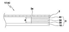
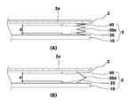
이하, 도1 내지 도4를 참조하여 본 발명에 따른 제1 구체예의 정전용량식 하이브리드 터치스크린(1A)을 설명한다.Hereinafter, the capacitive
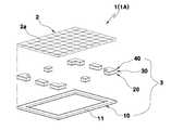
본 구체예에 적용된 압력검출-터치스크린모듈(3)은, 기판(10), 제1 극판(20), 탄성스페이서(30), 및 제2 극판(40)을 포함하는 구성으로 이루어진다.The pressure detection-
상기 기판(10)은 골격을 이루는 프레임 부재로서, 도1에 도시된 바와 같이, 둘레의 테두리(11)를 제외하고 내부가 관통된 링형 기판이거나, 도시하지는 않았지만 관통부가 없는 투명 전판으로 된 기판을 사용한다.The
기판(10)으로서 링형 기판이나 투명 전판을 사용하는 것은 기판으로 인해 그 아래에 배치되는 표시장치의 광투과율이 저하되는 것을 방지하기 위한 것으로서, 이와 같은 기판(10)의 구성에 따라 본 구체예의 터치스크린(1A)은 그 아래에 표시장치가 위치하여도 기판(10)의 존재로 인한 선명도 저하를 방지할 수 있다.The use of a ring-shaped substrate or a transparent electronic board as the
기판(10)의 소재로서는 관련 기술분야에서 통상적으로 사용되는 회로기판(PCB 및 FPCB) 등을 본 발명의 터치스크린이 사용되는 전기전자장치의 특성에 맞게 적절히 적용할 수 있으며, 링형일 경우에는 투명일 필요는 없지만, 전판일 경우에는 투명한 소재를 사용한다.As the material of the
상기 제1 극판(20)은 통상적인 정전용량식 터치스크린에 적용되는 일측 전극에 해당하는 전극 부재로서 동판과 같은 전도성 소재로 형성된다.The
제1 극판(20)은 기판(10)의 상면에 적층(접합)하되, 기판(10)의 테두리(11)를 따라 적층된다. 즉, 제1 극판(20)은 기판(10)이 링형일 경우 그 테두리(11) 위에 접합하고 투명 전판일 경우에는 외각 테두리에 접합한다.The
상기 탄성스페이서(30)는 제1 극판(20)의 상면에 상기 테두리(11)를 따라 적층된다.The
탄성스페이서(30)는 제1 극판(20)과 제2 극판(40) 사이에 존재하여 일종의 유전체로 작용하는 동시에 가해진 터치압력의 크기에 따라 그 높이가 복원성 있게 탄성적으로 가변됨으로써 가해진 압력의 크기에 따라 제1 극판(20)과 제2 극판(40) 사이의 거리(d)가 차이 나게 가변되도록 하며, 이로써 제1 극판(20)과 제2 극판(40)의 상하 중첩위치들인 센싱포인트(S)들에서의 정전용량 변화량은 터치압력의 크기에 따라 서로 다른 크기로 변화한다.The
탄성스페이서(30)의 소재와 형상은, 제1 극판(20)과 제2 극판(40) 사이의 거리(d)를 복원성 있게 탄성적으로 가변시킬 수 있는 소재와 형상이라면 특히 제한되지 아니하며, 예를 들어 폴리올레핀계, PVC계, 폴리스틸렌계, 폴리에스테르계, 폴리우레탄계, 폴리아미드계 등 널리 알려진 탄성소재, 특히 도1에 도시된 바와 같이, 탄성실리콘을 직육면체 등의 블록형상으로 성형하여 사용할 수 있다.The material and shape of the
탄성스페이서(30)는 터치압력의 크기에 따라 그 두께가 가변되어 제1 극판과 제2 극판 사이의 거리(d)를 가변시키고 압력이 사라지면 원위치로 복원되는 작용을 하는 부재이므로, 전술한 탄성실리콘과 같은 탄성합성수지뿐만 아니라, 도7에 도시된 바와 같은 기계적 스프링(30c: 도면에는 코일 스프링을 예시하였으나 리프스프 링과 같은 다른 스프링도 적용 가능함)이나 스프링 등이 장착되어 원위치로의 복원성을 가진 힌지구조(30d) 등과 같은 기계적 구조도 적용할 수 있다.Since the
이와 같은 기계적 구조의 탄성스페이서(30c, 30d)는, 도1 내지 도4와 같이 탄성스페이서(30)가 극판(20, 40) 사이에 위치하여 상하로 적층된 본 제1 구체예보다는, 탄성스페이서(30)가 극판(20, 40) 사이에 위치하지 않은 도5를 참조하여 이후에서 설명하는 제2 구체예의 터치스크린(1B)에 특히 적합하게 적용할 수 있다.The
상기 제2 극판(40)은 제1 극판(20)과 같이 동판으로 대표되는 전도성 소재로 형성되며, 탄성스페이서(30)의 상면에 기판(10)의 테두리(11)를 따라 적층됨으로써, 탄성스페이서(30)를 사이에 두고 제1 극판(20)의 상부에 일정 거리(d)만큼 이격되어 있다.The
앞서 설명한 바와 같이 제2 극판(40)의 상부에는 상기 위치검출-터치스크린모듈(2)이 적층되는바, 위치검출-터치스크린모듈(2)은 터치위치를 검출하고 터치압력을 압력검출-터치스크린모듈(3)에 전달하는 한편, 압력검출-터치스크린모듈(3)의 상부를 덮는 투명패널로서 기능한다.As described above, the position detection
이와 같이 제1 극판(20)과 제2 극판(40)이 탄성스페이서(30)를 사이에 두고 적층되어 있음에 따라, 제2 극판(40)은 탄성스페이서(30)의 높이에 대응하는 거리(d)를 두고 제1 극판(20)과 이격 배치되고, 제1 극판(20)과 제2 극판(40)의 상하 중첩위치(센싱포인트)는 가해진 압력에 의해 정전용량의 변화가 발생하며, 이런 정전용량의 변화량은 적당한 회로부로 측정할 수 있다.As such, the
즉, 위치검출-터치스크린모듈(2)을 터치하면, 그 터치압력에 의해 제2 극 판(40)과 탄성스페이스(30)가 가압되고 탄성스페이스(30)가 수축하면서 제1 극판(20)과 제2 극판(40) 사이의 거리(d)가 가변(줄어들게) 되고, 이런 거리(d)의 변화에 따라 제1 극판(20)과 제2 극판(40) 사이에서는 C=μA/d의 공식(여기에서 C는 정전용량, μ는 유전율, A는 면적, d는 극판 사이의 거리이다)에 해당하는 정전용량의 변화가 발생하고, 이때 전전용량의 변화량은 터치압력의 크기에 따라 다르게 나타난다.That is, when the position detection
이후 터치압력이 제거되면 탄성스페이서(30), 제2 극판(40) 및 위치검출-터치스크린모듈(2)은 탄성스페이서(30)의 복원력 및 자체의 탄성에 의해 원래 위치로 복귀된다.After the touch pressure is removed, the
제1 극판(20)과 제2 극판(40) 중에 적어도 하나의 극판(20, 40)은 기판(10)의 테두리(11)를 따라 일정 간격으로 4개 이상의 복수로 배열된다. 즉, 제1 극판(20)과 제2 극판(40)은 모두 4개 이상의 복수로 상하 쌍을 이루어 테두리(11)를 따라 일정 간격으로 배치되거나, 제1 극판(20)과 제2 극판(40) 중 어느 하나의 극판은 4개 이상의 복수이고 다른 하나의 극판은 전체의 테두리(11)를 따라 적층된 단수의 극판이다. 그러나 상기 단수의 극판은 반드시 1개일 필요는 없고 예를 들어 2-3개의 다수로 분할할 수도 있다.At least one
도3의 A는 제1 극판(20)과 제2 극판(40) 모두가 4개 이상의 복수로 형성된 예이고, 도3의 B와 C는 제1 극판(20)은 단수이고 제2 극판(40)이 4개 이상의 복수인 예이다.3A is an example in which both the
도1에 도시된 제1 구체예에 있어서는 테두리(11)의 4개의 코너와 4개의 변에 각각 제1 극판(20)과 제2 극판(40)을 배열하여 총 8쌍의 극판을 배치한 예를 도시한 것이다. 복수인 극판의 개수를 4개 이상으로 한 것은 이들 극판이 중첩 위치하는 센싱포인트(S)로부터 측정되는 4개 이상의 정전용량 변화량들로부터 터치압력의 크기를 정확하게 검출하기 위한 것이다. 복수의 극판의 개수가 3개 이하일 경우 센싱포인트(S)의 개수가 적어 정전용량 변화량 패턴이 단순하게 되므로 터치압력의 크기를 정확하게 검출하기 어려울 수 있어 바람직하지 않고, 지나치게 많은 경우에는 센싱포인트(S)의 개수가 많아 정전용량 변화량 패턴이 지나치게 복잡하여 연산 프로그램이 복잡해지는 문제가 있다.In the first embodiment shown in Fig. 1, an example in which a total of eight pairs of pole plates are arranged by arranging the
탄성스페이서(30)는 제1 극판(20)과 제2 극판(40) 사이의 탄성적 거리변화를 일으키는 작용을 하면 족하므로, 4개 이상인 복수의 극판(30 또는 40)마다 하나씩의 독립되게 적층할 수도 있고, 또는 전체의 테두리(11)를 따라 단수로 적층할 수도 있다. 탄성스페이서(30)를 단수로 할 경우 반드시 1개일 필요는 없고 예를 들어 2-3개의 다수로 분할할 수도 있다. 도3의 A와 B는 극판(20, 40) 사이마다 개별적으로 탄성스페이서(30)를 적층한 예이고, 도3의 C는 기판(10)의 테두리(11)를 따라 단수의 탄성스페이서(30)를 적층한 예이다.Since the
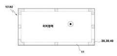
이상에서 설명한 바와 같이 본 구체예에 적용된 압력검출-터치스크린모듈(3)은, 기판(10)이 링형 또는 투명 전판으로 되어 있고, 그 위에 적층되는 제1 및 제2 극판(20, 40) 및 탄성스페이서(30)는 기판(10)의 테두리(11)에만 배치되며, 그 위에 투명한 위치검출-터치스크린모듈(2)이 적층되는 구조로서, 기판의 테두리(11)의 내부영역(도2에서 점선 내부 영역)이 터치영역이 되므로, 터치영역에서의 투명도가 우수하여 아래에 표시장치가 적층되어도 표시내용에 대한 선명도가 양호하다.As described above, the pressure detection-
2. 제2 구체예2. Second embodiment
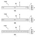
이하, 도5를 참조하여 본 발명에 따른 제2 구체예의 정전용량식 하이브리드 터치스크린(1B)을 설명한다.Hereinafter, the capacitive
제1 구체예에 적용된 압력검출-터치스크린모듈(3)은, 제1 극판(20)과 제2 극판(40)이 탄성스페이서(30)에 접하면서 상하에 적층된 상태로 기판(10)의 테두리(11)에 배열된 구조인 반면, 제2 구체예에 적용된 압력검출-터치스크린모듈(3)은, 탄성스페이스(30)가 기판(10)의 상면과 위치검출-터치스크린모듈(2)의 저면 사이에 일정 높이로 적층되는 한편, 제1 극판(20)과 제2 극판(40)은 일정 거리(d) 이격된 상태로 탄성스페이스(30)로부터 벗어나서 각각 기판(10)의 테두리(11)의 상면과 위치검출-터치스크린모듈(2)의 저면에 접합된 상태로 기판(10)의 테두리(11)에 배열된 구조이다.In the pressure detection-
제2 구체예에서는 탄성스페이서(30)가 탄성적 거리변화를 일으키는 작용만 하고, 상하 극판 사이에 존재하는 공기가 유전체로서 작용한다.In the second embodiment, the
제2 구체예에 있어서도, 제1 극판(20)과 제2 극판(40) 중에 적어도 하나의 극판(20, 40)은 기판(10)의 테두리(11)를 따라 일정 간격으로 4개 이상의 복수로 배열되고, 탄성스페이서(30)는 4개 이상인 복수의 극판(30 또는 40)마다 하나씩의 독립되게 적층할 수도 있고, 전체의 테두리(11)를 따라 단수로 적층할 수도 있다.Also in the second embodiment, at least one
제2 구체예에 있어서도, 위치검출-터치스크린모듈(2)을 가압하면 탄성스페이 서(30)가 압력에 의해 수축하면서 탄성스페이서(30)에 인접한 제1 극판(20)과 제2 극판(40) 사이의 거리(d)가 가변되고, 이런 거리(d)의 변화에 따라 각 센싱포인트(S)들에서 정전용량의 변화가 발생하게 된다.Also in the second embodiment, when the position detection-
3. 제3 구체예3. Third embodiment
이하, 도6을 참조하여 본 발명에 따른 제3 구체예의 정전용량식 하이브리드 터치스크린(1C)을 설명한다.Hereinafter, a capacitive
본 제3 구체예에 적용된 압력검출-터치스크린모듈(3)은, 탄성스페이서(30)를 제1 탄성스페이서(30a)와 제2 탄성스페이서(30b)의 이중구조로 하고, 이에 대응하여 제2 극판(40)을 상하 한쌍의 이중구조로 배치한 것이다.In the pressure detection-
즉, 제3 구체예에 적용된 압력검출-터치스크린모듈(3)은, 기판(10)의 테두리(11)의 상면에 제1 탄성스페이서(30a)가 적층되고, 제1 탄성스페이서(30a)의 상면에 제1 극판(20)이 적층되고, 제1 극판(20)의 상면에 다시 제2 탄성스페이서(30b)가 적층되고, 제2 탄성스페이서(30b)의 상면에 기판(10)의 전면을 커버하도록 위치검출-터치스크린모듈(2)이 적층되는 한편, 기판(10)의 테두리(11)의 상면과 위치검출-터치스크린모듈(2)의 저면에 제1 극판(20)과 일정 간격 이격되게 제2 극판(40)이 각각 적층된 이중 구조이다.That is, in the pressure detection-
도6에 도시된 구체예는, 제1 극판(20)을 제1 탄성스페이서(30a)의 상면에 적층하되 제1 탄성스페이서(30a)의 면적을 초과하는 넓이로 적층하고, 제2 탄성스페이서(30b)를 제1 극판(20) 위에 적층하되 제1 극판(20)의 초과부위(21) 위에 적층하고, 기판(10)의 테두리(11)의 상면과 위치검출-터치스크린모듈(2)의 저면에 제1 극판(20)과 상하로 일정 거리(d) 이격되게 제2 극판(40)을 각각 적층한 이중 구조가 예시되어 있지만, 기판의 테두리(11) 위에 제2 극판(40)을 적층하고, 제2 극판(40) 위에 제1 탄성스페이서(30a), 제1 극판(20), 제2 탄성스페이서(30b), 제2 극판(40) 및 위치검출-터치스크린모듈(2)을 차례로 적층한 이중구조도 적용할 수 있음은 당연하다.6, the
제3 구체예에 있어서도, 위치검출-터치스크린모듈(2)을 터치하면 탄성스페이서(30a, 30b)가 터치압력에 의해 수축하면서 탄성스페이서(30a, 30b) 사이의 제1 극판(20)과 그 상하의 한쌍의 제2 극판(40) 사이의 거리(d)가 가변(줄어들게) 되고, 이런 거리의 변화에 따라 각 센싱포인트(S)들에서 정전용량의 변화가 발생하게 된다.Also in the third embodiment, when the position detection-
또한 제3 구체예에 있어서도, 제1 극판(20)과 제2 극판(40) 중에 적어도 하나의 극판(20, 40)은 기판(10)의 테두리(11)를 따라 일정 간격으로 4개 이상의 복수로 배열되고, 탄성스페이서(30a, 30b)는 4개 이상인 복수의 극판(30 또는 40)마다 하나씩의 독립되게 적층할 수도 있고, 기판(10)의 테두리(11) 전체를 커버하도록 단수로 적층할 수 있다.Also in the third embodiment, at least one
이중구조인 본 구체예의 압력검출-터치스크린모듈(3)은 각각의 센싱포인트(S)에 대해 상하 2개의 정전용량 변화량을 측정할 수 있어 터치압력의 검출 감도를 향상시킬 수 있는 장점이 있다.The pressure detection-
4. 터치위치 및 터치압력의 검출4. Detection of touch position and touch pressure
이하, 본 발명에 따른 정전용량식 하이브리드 터치스크린(1)에 의한 터치위치와 터치압력의 검출, 제1 입력신호, 제2 입력신호 및 최종 목적 입력신호의 생성에 대해 설명한다.Hereinafter, detection of the touch position and the touch pressure, generation of the first input signal, the second input signal, and the final destination input signal by the capacitive
먼저, 위치검출-터치스크린모듈(2)에 의한 '터치위치' 검출은, 종래에 널리 알려진 ITO 터치스크린에서와 마찬가지로, 예를 들어 격자 배치의 매트릭스 전극(2a)의 특정 위치에 손가락과 같은 도체가 터치할 때 발생하는 터치된 전극에서의 기생 정전용량변화를 검출함으로써 도체가 어느 위치에 터치하였는지를 전기적으로 검출하여 이루어지며, 이렇게 검출된 터치위치는 목적 입력신호를 생성하기 위한 제1 입력신호로 사용된다.First, the 'touch position' detection by the position detection-
목적 입력신호의 다른 성분인 '터치압력'은 압력검출-터치스크린모듈(3)에서 검출되는바, 이하에서는 압력검출-터치스크린모듈(3)로서, 기판(10)의 테두리(11)의 4개의 코너에 각각 제1 극판(20), 탄성스페이서(30) 및 제2 극판(40)의 적층하여 4개의 코너가 센싱포인트(S)가 되게 모듈(도8 참조)과, 기판의 테두리(11)의 4개의 변 중간에 각각 제1 극판(20), 탄성스페이서(30) 및 제2 극판(40)의 적층하여 4개의 변이 센싱포인트(S)가 되게 한 모듈(도9 참조)을 적용한 예에 대해 예시적으로 설명한다.'Touch pressure', another component of the desired input signal, is detected by the pressure detection-
도8과 도9에서 F는 특정 터치포인트(P)에 가해진 압력의 크기, L과 N은 압력검출-터치스크린모듈(3)의 가로길이와 세로길이를 나타내며, 해당 터치포인트(P)에 F의 압력이 가해질 때, 각각의 센싱포인트(S)에서 측정되는 압력의 크기를 각각 f1, f2, f3 및 f4 이다. 좌표의 원점은 도8에서는 좌하의 코너이고, 도9에서는 좌 측변의 중심으로 설정하였다.8 and 9, F denotes the magnitude of the pressure applied to a specific touch point P, and L and N denote the horizontal length and the vertical length of the pressure detection-
움직이지 않은 강체에 작용하는 모든 힘의 벡터의 합과 모멘트(M)의 벡터의 합은 각각 0인바, 터치스크린(1)에 F의 힘을 가할 때 터치스크린은 실질적으로 움직이거나 회전하지 아니하므로 ΣF와 ΣM은 0이다.The sum of the vector of all the forces acting on the rigid body and the sum of the vectors of the moment (M) is respectively 0, so that when the force of F is applied to the
도8과 같이 좌표축을 설정할 경우, 전체의 힘(F)의 합은 0이고, X축과 Y축 방향으로는 힘이 존재하지 않으므로 ΣFx=0 및 ΣFy=0이고, Z축에서 누르는 압력 F와 각 센싱포인트(S)에서 측정되는 반대방향의 압력의 크기 f1, f2, f3 및 f4의 합은 같으므로, ΣFz=0에서F=f1+f2+f3+f4 (식1)가 된다.When the coordinate axis is set as shown in Fig. 8, the sum of the total force F is 0, and there is no force in the X and Y axis directions, so ΣFx = 0 and ΣFy = 0, and the pressure F pressed on the Z axis Since the sum of the magnitudes f1, f2, f3, and f4 in the opposite directions measured at each sensing point S is the same,F = f1 + f2 + f3 + f4 (Equation 1) at ΣFz = 0.
전체 모멘트 합은 0에서, Z축으로는 회전 모멘트가 없으므로 ΣMz=0이다.The total moment sum is zero, and there is no rotation moment on the Z axis, so ΣMz = 0.
X축을 중심으로 회전시키는 모멘트는, 힘 f2와 f3이 거리 N만큼 떨어진 곳에서 각각 N·f2 와 N·f3의 크기로 반시계 방향으로 작용하고 있고, 힘 F가 거리 y 만큼 떨어진 위치에서 y·F의 크기로 시계방향으로 작용하므로,The moment to rotate about the X axis acts counterclockwise in the magnitude of N · f2 and N · f3 where the forces f2 and f3 are separated by the distance N, respectively, and the force F is positioned at the distance y Since it works clockwise with the magnitude of F,
ΣMx=0에서 -y·F + N·f2 + N·f3 = 0 이므로 y는N(f2+f3)/F (식2)가 된다.At ΣMx = 0, y isN (f2 + f3) / F (Equation 2) since -y F + N f2 + N f3 = 0.
y축을 중심으로 회전시키는 모멘트는 힘 f3와 f4가 거리 L만큼 떨어진 곳에서 각각 L·f3와 L·f4의 크기로 반시계 방향으로 작용하고 있고, 힘 F가 거리 x 만큼 떨어진 위치에서 x·F 의 크기로 시계방향으로 작용하고 있다.The moment of rotation about the y-axis acts counterclockwise with the magnitudes of L · f3 and L · f4 where the forces f3 and f4 are separated by the distance L, respectively, and the force F is separated by the distance x. It is working clockwise at the size of.
따라서 ΣMy=0에서 x·F - L·f3 - L·f4 = 0이므로,x = L(f3+f4)/F (식3)가 된다.Therefore, x = F-L-f3-L-f4 = 0 at ΣMy = 0, wherebyx = L (f3 + f4) / F (Equation 3).
결국, 각각의 센싱포인트(S)들에서 측정된 f1, f2, f3, f4로부터 위 식1을 통해 가해진 터치압력의 크기를 알 수 있고, 본 발명에 필요하지 아니하지만 식2와 식3에서 그 좌표(터치위치)도 알 수 있다.As a result, it is possible to know the magnitude of the touch pressure applied through
도9와 같이 좌표축을 설정할 경우 도8의 설명과 동일하게 적용하면, X축과 Y축의 방향으로는 힘이 존재하지 아니하고 ΣFz=0에서F=f1+f2+f3+f4 (식4)이다.In the case of setting the coordinate axis as shown in Fig. 9, the same applies to the description in Fig. 8, where no force exists in the directions of the X and Y axes, andF = f1 + f2 + f3 + f4 (Equation 4) at? Fz = 0.
전체 모멘트 합은 0에서, Z축으로는 회전 모멘트가 없으므로 ΣMz=0이다.The total moment sum is zero, and there is no rotation moment on the Z axis, so ΣMz = 0.
X축을 중심으로 회전시키는 모멘트는 힘 f2가 N/2 떨어진 곳에서는 N·f2/2의 크기로 반시계 방향으로, 힘 f4는 N/2 떨어진 곳에서 N·f4/2의 크기로 시계방향으로 작용하고 있고, y 떨어진 위치에서 힘 F가 시계방향으로 y·F의 크기로 작용하므로(f1과 f3은 X축 위에 존재하므로 모멘트를 발생시키지 않음),The moment of rotation about the X axis is counterclockwise in the direction of N · f2 / 2 where the force f2 is N / 2 away and clockwise in the direction of N · f4 / 2 at the distance N / 2 away. And the force F acts clockwise in the y-distinct position (f1 and f3 do not generate moments because they are on the X-axis)
ΣMx=0에서, -y·F + N·f2/2 - N·f4/2 = 0이므로,y=N·(f2-f4)/2F (식 5)가 된다.At Σ Mx = 0, since -y F + N f2 / 2-N f4 / 2 = 0,y = N f (f2-f4) / 2F (Expression 5).
마찬가지로 Y축을 중심으로 회전시키는 모멘트는 힘 f2와 f4가 거리 L/2만큼 떨어진 곳에서 각각 L·f2/2와 L·f4/2의 크기로 반시계 방향으로 작용하고 있고, L 만큼 떨어진 위치에서 L·f3의 크기로 반시계 방향으로 작용하고 있고, 또한 힘 F가 거리 x만큼 떨어진 위치에서 x·F 의 크기로 시계방향으로 작용하고 있으므로, ΣMy=0에서, x·F - L·f2/2 - L·f4/2 - L·f3 = 0 이므로,x=L(f2+2f3+f4)/2F(식 6)가 된다.Similarly, the moment of rotation about the Y axis acts counterclockwise in the magnitude of L · f2 / 2 and L · f4 / 2 where the forces f2 and f4 are separated by the distance L / 2, respectively. Since it acts counterclockwise with the magnitude of L · f3 and the force F acts clockwise with the magnitude of x · F at a position separated by the distance x, at ΣMy = 0, x · F − L · f2 / Since 2-L f4 / 2-L f3 = 0,x = L (f2 + 2f3 + f4) / 2F (Equation 6).
따라서 도8에서와 마찬가지로 센싱포인트(S)들에서 측정된 f1, f2, f3, f4로부터 식4를 통해 터치압력의 크기를 알 수 있고, 본 발명에서 필요하지 않지만 식5와 식6을 통해 좌표도 알 수 있다.Therefore, as in FIG. 8, the magnitude of the touch pressure can be known from equations f1, f2, f3, and f4 measured at the sensing points S through Equation 4. It can also be seen.
상기 도8과 도9의 경우의 예에서 좌표축을 어느 위치에 설정하더라도 같은 방법을 적용하면 된다. 상기와 같이 설정한 임의의 좌표축에 대하여 추출한 결과치는 사용자가 원하는 다른 좌표축에 대해 좌표변환을 통하여 사용할 수 있다.In the example of FIGS. 8 and 9, the same method may be applied to any position of the coordinate axis. The result value extracted for the arbitrary coordinate axis set as described above may be used through coordinate transformation for another coordinate axis desired by the user.
도8과 도9는 상기 복수의 극판(즉, 센싱포인트)이 4개인 경우를 예시한 것이며, 4개 이상 복수의 센싱포인트에 대해서도 마찬가지의 원리로 터치압력의 크기와 터치위치를 알 수 있다.8 and 9 illustrate a case in which the plurality of pole plates (ie, sensing points) are four, and the magnitude and touch position of the touch pressure can be known based on the same principle for four or more sensing points.
이와 같이, 특정 터치포인트(P)에 가해진 특정 크기의 터치압력(F)에 대해, 각 센싱포인트(S)에서의 정전용량의 변화를 측정할 수 있고, 이런 정전용량의 변화량은 터치압력의 크기(F)에 따라 다르게 되므로, 정전용량의 변화량과 터치압력의 크기에 관한 관계로부터 터치압력의 크기와 상관관계가 있는 전기적 신호를 얻을 수 있다.As described above, with respect to the touch pressure F having a specific magnitude applied to the specific touch point P, the change in capacitance at each sensing point S can be measured, and the amount of change in capacitance is the magnitude of the touch pressure. Since it depends on (F), an electrical signal correlated with the magnitude of the touch pressure can be obtained from the relation regarding the amount of change in capacitance and the magnitude of the touch pressure.
본 발명의 터치스크린에 적용된 압력검출-터치스크린모듈(3)은 터치압력 뿐만 아니라 터치위치까지를 검출할 수도 있지만, 본 발명의 터치스크린(1)에서 터치위치는 위치검출-터치스크린모듈(2)에 의해 검출되므로 압력검출-터치스크린모듈(3)은 터치위치는 검출하지 아니하고 단지 터치압력(F=f1+f2+f3+f4)만을 검출하여 목적 입력신호의 구성성분인 제2 입력신호로 사용하게 되며, 따라서 터치압력과 함께 터치위치까지를 검출해야 하는 것에 따른 압력검출-터치스크린모듈(3)의 정교성 부담을 경감할 수 있다.Although the pressure detection-
본 발명에 따른 터치스크린에 의하면, 위치검출-터치스크린모듈(2)로부터의 터치위치 신호(제1 입력신호)와 압력검출-터치스크린모듈(3)로부터의 터치압력 신 호(제2 입력신호)를 조합하여(즉, 터치위치와 터치압력을 조합하여), 목적하는 최종 입력신호를 생성할 수 있으므로, 이를 활용할 수 있은 다양한 소프트웨어와 접목하면, 종래 터치스크린과는 비교할 수 없는 매우 다양한 입력신호를 구현할 수 있도록 한다.According to the touch screen according to the present invention, the touch position signal (first input signal) from the position detection-
즉, 목적하는 최종 입력신호의 특성에 맞게, 터치위치만이 필요한 경우에는 터치위치 신호(제1 입력신호)만을 목적하는 최종 입력신호로 사용할 수도 있고, 터치압력만이 필요한 경우에는 터치압력 신호(제2 입력신호)만을 목적하는 최종 입력신호로 사용할 수도 있으며, 터치위치와 터치압력 모두 필요한 경우에는 터치위치 신호(제1 입력신호)와 터치압력 신호(제2 입력신호)를 조합하여(즉, 터치위치와 터치압력을 조합하여) 목적하는 최종 입력신호를 생성할 수 있으므로, 이를 활용할 수 있은 다양한 소프트웨어와 접목하면, 종래 터치스크린과는 비교할 수 없는 매우 다양한 입력신호를 구현할 수 있도록 한다.That is, according to the characteristics of the desired final input signal, when only the touch position is required, only the touch position signal (first input signal) may be used as the final input signal for the purpose. The second input signal may be used as the final input signal for the purpose. When both the touch position and the touch pressure are required, the touch position signal (first input signal) and the touch pressure signal (second input signal) may be combined (that is, By combining the touch position and the touch pressure) to generate the desired final input signal, when combined with a variety of software that can utilize this, it is possible to implement a wide variety of input signals that can not be compared with the conventional touch screen.
본 발명에 따른 터치스크린의 활용을 예를 들어 설명하면, MP3 곡목을 선택하기 위해 스크롤 기능의 가속키를 작동할 때 종래에는 스크롤바가 지속적으로 눌려지고 있는 시간을 측정하여 가속키 입력신호를 생성할 수밖에 없었지만, 본 발명에 의하면 터치압력의 크기를 활용하여 누르는 압력의 세기에 따라 가속키 입력신호를 생성할 수 있다.Using the touch screen according to the present invention will be described by way of example, when operating the acceleration key of the scroll function to select the MP3 songs conventionally measure the time the scroll bar is continuously pressed to generate the acceleration key input signal Inevitably, according to the present invention, the acceleration key input signal may be generated according to the strength of the pressure to be pressed by utilizing the magnitude of the touch pressure.
다른 예로서 각종 게임 콘텐츠에 본 발명의 터치스크린을 활용할 경우, 터치압력의 크기에 따라 힘을 시뮬레이션 하는 게임에 직접 활용할 수 있을 뿐 아니라 변화하는 정도를 표현하거나 조절하는 곳에도 사용 가능하다. 예를 들어 격투기 게 임의 경우 압력의 크기에 따라 타격의 크기를 전달할 수 있고 골프게임의 경우 타구의 세기를 사용자가 누르는 힘에 비례하여 제어되도록 할 수 있다. 또한 스포츠 오락게임기에서 예를 들어 점프하는 작동 역시 압력의 크기에 따라 점프는 높낮이를 현실성 있게 구현할 수 있다.As another example, when using the touch screen of the present invention for various game contents, not only can be directly used in the game simulating the force according to the size of the touch pressure, but also used to express or adjust the degree of change. For example, in the case of martial arts, the magnitude of the hit may be transmitted according to the magnitude of the pressure, and in the case of a golf game, the strength of the batting may be controlled in proportion to the force pressed by the user. In addition, for example, the jumping operation in a sports entertainment game machine can realistically realize the height of the jump according to the magnitude of the pressure.
또 다른 예로서, 휴대전화기의 키패드에서와 같이 키입력에 적용된 종래의 터치스크린에서는 하나의 키가 한두 가지 기능 밖에 할 수 없었으나, 본 발명에 의하면 하나의 키로 사용자가 누르는 힘의 세기에 따라 다양한 입력신호를 생성할 수 있다. 예를 들어 본 발명의 터치스크린을 적용한 휴대전화기의 숫자키는 숫자입력 기능 외에도 해당 숫자를 누르는 힘의 크기에 따라 다른 작동을 입력하도록 구현할 수 있다.As another example, in a conventional touch screen applied to key input as in a keypad of a mobile phone, only one key can perform one or two functions, but according to the present invention, a single key varies according to the strength of a user's pressing force. An input signal can be generated. For example, the numeric key of the mobile phone to which the touch screen of the present invention is applied can be implemented to input different operations according to the magnitude of the force for pressing the number in addition to the numeric input function.
5. 기타 구체예5. Other embodiments
도1의 구체예를 통해 설명한 바와 같이, 본 발명에 따른 정전용량식 하이브리드 터치스크린(1)은, 투명의 정전용량식 위치검출-터치스크린모듈(2)의 바로 아래에 압력검출-터치스크린모듈(3)을 적층하고, 표시장치는 압력검출-터치스크린모듈(3)의 아래에 적층하여 사용하는 것을 기본으로 하지만, 박막의 플렉시블한 표시장치가 적용된 경우 표시장치를 위치검출-터치스크린모듈(2)과 압력검출-터치스크린모듈(3) 사이에 적층하여 위치검출-터치스크린모듈(2)에 가해진 터치압력이 표시장치를 통해 압력검출-터치스크린모듈(3)에 전달되도록 할 수 있다. 이와 같은 구체예의 경우, 위치검출-터치스크린모듈(2)은 투명하고 압력검출-터치스크린모듈(3) 은 표시장치의 아래에 위치하므로, 본 발명의 터치스크린(1)에 의해 기판(10)의 존재로 인한 선명도 저하가 일어나지 아니하며, 따라서 기판(10)으로서 전술한 바와 같은 관통된 링형 판이나 투명 전판을 사용할 필요가 없다.As described with reference to the embodiment of FIG. 1, the capacitive
또한 본 발명에 적용된 압력검출-터치스크린모듈(3)에서 기판(10)은 그 위에 적층되는 제1 극판(20) 등의 지지체이므로, 압력검출-터치스크린모듈(3)이 다른 장치(예, 표시장치) 위에 적층되면서 다른 장치의 상면을 지지체로 사용할 경우 제1 내지 제3 구체예에서 기판(10)은 생략하고 다른 장치 위에 제1 극판 등을 바로 적층할 수 있다.In addition, since the
아울러, 제1 구체예 내지 제3 구체예에 있어서, 탄성스페이서(30)들은 터치압력에 의해 아래로 가압되었던 제2 극판(40)을 원위치로 복원시키는 작용을 하는 것인바, 만약 본 발명의 터치스크린(1)이나 본 발명의 터치스크린(1)이 장착되는 휴대전화기와 같은 전기전자장치들의 하우징 등에 탄성스페이서(30)와 동일한 작용을 하는 임의의 지지체가 존재한다면, 압력검출-터치스크린모듈(3) 자체에는 탄성스페이서(30)를 생략하고 제1 극판(20)과 제2 극판(40)을 일정거리 이격된 상태로 적층하면 족하며(이 경우 공기가 유전체가 된다), 이때 외부의 지지체는 본 발명의 구체예에 적용된 탄성스페이서(30)로 보아야 할 것이다.In addition, in the first to third embodiments, the
또한 첨부도면은 본 발명의 터치스크린(1)의 전체 형상이 사각형인 예를 설명하였으나, 그 형상은 원형 등 다른 형상으로 형성할 수도 있음은 당연하다.In addition, although the accompanying drawings described an example in which the overall shape of the
도1은 본 발명에 따른 제1 구체예의 터치스크린의 개략 분해사시도,1 is a schematic exploded perspective view of a touch screen of a first embodiment according to the present invention;
도2는 도1의 개략 평면도,2 is a schematic plan view of FIG. 1;
도3은 도1의 개략 정면도,3 is a schematic front view of FIG. 1;
도4는 도1의 개략 부분단면도,4 is a schematic partial cross-sectional view of FIG.
도5는 본 발명에 따른 제2 구체예의 터치스크린의 개략 부분단면도,5 is a schematic partial cross-sectional view of a touch screen of a second embodiment according to the present invention;
도6은 본 발명에 따른 제3 구체예의 터치스크린의 개략 부분단면도,6 is a schematic partial cross-sectional view of a touch screen of a third embodiment according to the present invention;
도7은 다른 예의 탄성스페이서가 적용된 본 발명에 따른 터치스크린의 개략 부분단면도,7 is a schematic partial cross-sectional view of a touch screen according to the present invention to which an elastic spacer of another example is applied;
도8과 도9는 본 발명에 따른 터치스크린의 터치위치와 압력을 검출하는 원리를 보여주는 도면.8 and 9 are views showing the principle of detecting the touch position and pressure of the touch screen according to the present invention.
<도면의 주요 부분에 대한 부호의 설명><Explanation of symbols for the main parts of the drawings>
1, 1A, 1B, 1C: 본 발명의 터치스크린1, 1A, 1B, 1C: touch screen of the present invention
2: 위치검출-터치스크린모듈2: Position Detection-Touch Screen Module
2a: 매트릭스 전극2a: matrix electrode
3: 압력검출-터치스크린모듈3: Pressure Detection-Touch Screen Module
10: 기판10: Substrate
11: 테두리 20: 제1 극판11: border 20: first electrode plate
30, 30a, 30b, 30c, 30d: 탄성스페이서 40: 제2 극판30, 30a, 30b, 30c, 30d: elastic spacer 40: second electrode plate
50: 투명터치패널 S: 센싱포인트50: transparent touch panel S: sensing point
Claims (5)
Translated fromKoreanPriority Applications (1)
| Application Number | Priority Date | Filing Date | Title |
|---|---|---|---|
| KR1020090131486AKR101097869B1 (en) | 2009-12-28 | 2009-12-28 | Hybrid Capacitive Touch Screen |
Applications Claiming Priority (1)
| Application Number | Priority Date | Filing Date | Title |
|---|---|---|---|
| KR1020090131486AKR101097869B1 (en) | 2009-12-28 | 2009-12-28 | Hybrid Capacitive Touch Screen |
Publications (2)
| Publication Number | Publication Date |
|---|---|
| KR20110075134A KR20110075134A (en) | 2011-07-06 |
| KR101097869B1true KR101097869B1 (en) | 2011-12-23 |
Family
ID=44915180
Family Applications (1)
| Application Number | Title | Priority Date | Filing Date |
|---|---|---|---|
| KR1020090131486AExpired - Fee RelatedKR101097869B1 (en) | 2009-12-28 | 2009-12-28 | Hybrid Capacitive Touch Screen |
Country Status (1)
| Country | Link |
|---|---|
| KR (1) | KR101097869B1 (en) |
Families Citing this family (14)
| Publication number | Priority date | Publication date | Assignee | Title |
|---|---|---|---|---|
| KR101349703B1 (en)* | 2012-01-09 | 2014-01-16 | 한국표준과학연구원 | Touch input structure sensing multi-touch and single intensity of force, and method for manufacturing the same |
| KR101907463B1 (en)* | 2012-02-24 | 2018-10-12 | 삼성전자주식회사 | Composite touch screen and operating method thereof |
| KR101934310B1 (en) | 2012-08-24 | 2019-01-03 | 삼성디스플레이 주식회사 | touch display apparatus sensing touch force |
| KR102043691B1 (en) | 2012-12-20 | 2019-11-13 | 삼성디스플레이 주식회사 | Touch detection method and touch detection system |
| KR101506511B1 (en)* | 2013-09-23 | 2015-04-07 | 주식회사 하이딥 | Capacitive location and pressure touch sensing device |
| KR102228561B1 (en) | 2014-10-01 | 2021-03-16 | 삼성디스플레이 주식회사 | Display device indlucing touch sensor |
| KR101641026B1 (en)* | 2015-08-15 | 2016-07-19 | 주식회사 우정하이텍 | Capacitive type metal plate touch pad with accurate and stable touch recognition |
| KR101742584B1 (en)* | 2015-09-02 | 2017-06-01 | 주식회사 하이딥 | Touch pressure detectable touch input device |
| KR101655431B1 (en)* | 2015-12-22 | 2016-09-07 | (주)멜파스 | 3 dimension touch screen panel |
| US20190004630A1 (en)* | 2015-12-14 | 2019-01-03 | Melfas Inc. | Three-dimensional touch screen panel and pressure sensing layer thereof |
| KR102563454B1 (en) | 2016-04-26 | 2023-08-03 | 엘지디스플레이 주식회사 | Pressure sensor integrated organic light emitting display device and touch screen integrated organic light emitting display device |
| KR102659420B1 (en) | 2016-09-27 | 2024-04-22 | 삼성디스플레이 주식회사 | Display device |
| KR102410542B1 (en) | 2017-05-29 | 2022-06-20 | 삼성전자주식회사 | Electronic device comprising a module mounted on sunken area of layer |
| CN120405301B (en)* | 2025-07-03 | 2025-09-30 | 江西众联光电科技有限公司 | Touch screen quality detection platform |
- 2009
- 2009-12-28KRKR1020090131486Apatent/KR101097869B1/ennot_activeExpired - Fee Related
Also Published As
| Publication number | Publication date |
|---|---|
| KR20110075134A (en) | 2011-07-06 |
Similar Documents
| Publication | Publication Date | Title |
|---|---|---|
| KR100943989B1 (en) | Capacitive touch screen | |
| KR101097869B1 (en) | Hybrid Capacitive Touch Screen | |
| JP5611282B2 (en) | Force imaging input devices and systems | |
| KR101233021B1 (en) | Single sided capacitive force sensor for electronic devices | |
| JP5722954B2 (en) | Touch panel with pressure detection function | |
| CN106445097A (en) | Electronic devices with shear force sensing | |
| KR101532403B1 (en) | Resistive type touch film for capacitive touch panel | |
| KR20130104051A (en) | Touch screen apparatus and method thereof | |
| KR20150096104A (en) | Display Device Having Tri-axis Sensing Type Capacitive Touch Screen | |
| EP3769191B1 (en) | Passive mechanical keyboard | |
| JPWO2017029860A1 (en) | Capacitive input device | |
| KR100787834B1 (en) | Capacitive input device | |
| KR101145156B1 (en) | Capacitive Force-based Touch Screen | |
| KR100894250B1 (en) | Capacitive Input / Indicator | |
| US20220137716A1 (en) | Measuring Capacitance | |
| KR20140136353A (en) | Capacitive Force-based Input Device Using Elasticity of Housing | |
| KR20150002326A (en) | Touch sensing device and manufacturing method of the same | |
| KR20110124089A (en) | Capacitive Input | |
| KR20110124995A (en) | Capacitive Input | |
| KR101057491B1 (en) | Capacitive Input | |
| KR20120097590A (en) | Capacitive force-based input device | |
| KR20120138958A (en) | Capacitive force-based input device | |
| KR20110123377A (en) | Capacitive Input | |
| KR20110110451A (en) | How to input gesture gesture on touch screen |
Legal Events
| Date | Code | Title | Description |
|---|---|---|---|
| A201 | Request for examination | ||
| PA0109 | Patent application | St.27 status event code:A-0-1-A10-A12-nap-PA0109 | |
| PA0201 | Request for examination | St.27 status event code:A-1-2-D10-D11-exm-PA0201 | |
| R18-X000 | Changes to party contact information recorded | St.27 status event code:A-3-3-R10-R18-oth-X000 | |
| PN2301 | Change of applicant | St.27 status event code:A-3-3-R10-R13-asn-PN2301 St.27 status event code:A-3-3-R10-R11-asn-PN2301 | |
| D13-X000 | Search requested | St.27 status event code:A-1-2-D10-D13-srh-X000 | |
| D14-X000 | Search report completed | St.27 status event code:A-1-2-D10-D14-srh-X000 | |
| E902 | Notification of reason for refusal | ||
| PE0902 | Notice of grounds for rejection | St.27 status event code:A-1-2-D10-D21-exm-PE0902 | |
| P11-X000 | Amendment of application requested | St.27 status event code:A-2-2-P10-P11-nap-X000 | |
| P13-X000 | Application amended | St.27 status event code:A-2-2-P10-P13-nap-X000 | |
| PG1501 | Laying open of application | St.27 status event code:A-1-1-Q10-Q12-nap-PG1501 | |
| E701 | Decision to grant or registration of patent right | ||
| PE0701 | Decision of registration | St.27 status event code:A-1-2-D10-D22-exm-PE0701 | |
| GRNT | Written decision to grant | ||
| PR0701 | Registration of establishment | St.27 status event code:A-2-4-F10-F11-exm-PR0701 | |
| PR1002 | Payment of registration fee | St.27 status event code:A-2-2-U10-U11-oth-PR1002 Fee payment year number:1 | |
| PG1601 | Publication of registration | St.27 status event code:A-4-4-Q10-Q13-nap-PG1601 | |
| PN2301 | Change of applicant | St.27 status event code:A-5-5-R10-R13-asn-PN2301 St.27 status event code:A-5-5-R10-R11-asn-PN2301 | |
| P14-X000 | Amendment of ip right document requested | St.27 status event code:A-5-5-P10-P14-nap-X000 | |
| P16-X000 | Ip right document amended | St.27 status event code:A-5-5-P10-P16-nap-X000 | |
| Q16-X000 | A copy of ip right certificate issued | St.27 status event code:A-4-4-Q10-Q16-nap-X000 | |
| S20-X000 | Security interest recorded | St.27 status event code:A-4-4-S10-S20-lic-X000 | |
| R18-X000 | Changes to party contact information recorded | St.27 status event code:A-5-5-R10-R18-oth-X000 | |
| R18-X000 | Changes to party contact information recorded | St.27 status event code:A-5-5-R10-R18-oth-X000 | |
| FPAY | Annual fee payment | Payment date:20141229 Year of fee payment:4 | |
| PR1001 | Payment of annual fee | St.27 status event code:A-4-4-U10-U11-oth-PR1001 Fee payment year number:4 | |
| R18-X000 | Changes to party contact information recorded | St.27 status event code:A-5-5-R10-R18-oth-X000 | |
| FPAY | Annual fee payment | Payment date:20151204 Year of fee payment:5 | |
| PR1001 | Payment of annual fee | St.27 status event code:A-4-4-U10-U11-oth-PR1001 Fee payment year number:5 | |
| R18-X000 | Changes to party contact information recorded | St.27 status event code:A-5-5-R10-R18-oth-X000 | |
| LAPS | Lapse due to unpaid annual fee | ||
| PC1903 | Unpaid annual fee | St.27 status event code:A-4-4-U10-U13-oth-PC1903 Not in force date:20161217 Payment event data comment text:Termination Category : DEFAULT_OF_REGISTRATION_FEE | |
| PC1903 | Unpaid annual fee | St.27 status event code:N-4-6-H10-H13-oth-PC1903 Ip right cessation event data comment text:Termination Category : DEFAULT_OF_REGISTRATION_FEE Not in force date:20161217 | |
| P22-X000 | Classification modified | St.27 status event code:A-4-4-P10-P22-nap-X000 |