KR101096462B1 - Electric lock - Google Patents
Electric lockDownload PDFInfo
- Publication number
- KR101096462B1 KR101096462B1KR1020090080401AKR20090080401AKR101096462B1KR 101096462 B1KR101096462 B1KR 101096462B1KR 1020090080401 AKR1020090080401 AKR 1020090080401AKR 20090080401 AKR20090080401 AKR 20090080401AKR 101096462 B1KR101096462 B1KR 101096462B1
- Authority
- KR
- South Korea
- Prior art keywords
- housing
- locking member
- locking
- shaft
- shaft hole
- Prior art date
- Legal status (The legal status is an assumption and is not a legal conclusion. Google has not performed a legal analysis and makes no representation as to the accuracy of the status listed.)
- Expired - Fee Related
Links
Images


Classifications
- E—FIXED CONSTRUCTIONS
- E05—LOCKS; KEYS; WINDOW OR DOOR FITTINGS; SAFES
- E05B—LOCKS; ACCESSORIES THEREFOR; HANDCUFFS
- E05B47/00—Operating or controlling locks or other fastening devices by electric or magnetic means
- E05B47/0046—Electric or magnetic means in the striker or on the frame; Operating or controlling the striker plate
- E—FIXED CONSTRUCTIONS
- E05—LOCKS; KEYS; WINDOW OR DOOR FITTINGS; SAFES
- E05B—LOCKS; ACCESSORIES THEREFOR; HANDCUFFS
- E05B47/00—Operating or controlling locks or other fastening devices by electric or magnetic means
- E05B47/0001—Operating or controlling locks or other fastening devices by electric or magnetic means with electric actuators; Constructional features thereof
- E05B47/0002—Operating or controlling locks or other fastening devices by electric or magnetic means with electric actuators; Constructional features thereof with electromagnets
Landscapes
- Physics & Mathematics (AREA)
- Electromagnetism (AREA)
- Electromagnets (AREA)
- Lock And Its Accessories (AREA)
Abstract
Translated fromKoreanDescription
Translated fromKorean본 발명은 전기 잠금장치에 관한 것으로, 보다 상세하게는 전기를 이용하는 전기 잠금장치에서 고정수단으로 이용되는 핀과 플런저 및 하우징의 구조를 변경하여 잠금장치의 본체를 구성하는 하우징이나 도어 프레임의 변형을 방지할 수 있는 전기 잠금장치에 관한 것이다.The present invention relates to an electric locking device, and more particularly, to modify the structure of the housing or door frame constituting the main body of the locking device by changing the structure of the pin, the plunger and the housing used as the fixing means in the electric locking device using electricity. An electric lock that can be prevented.
현재 일반 가정, 상점, 정부 기관, 기업 등은 인가되지 않은 외부인의 출입을 제한하기 위한 출입 통제 시스템을 널리 사용하고 있다.Currently, homes, shops, government agencies, and businesses are widely using access control systems to restrict unauthorized outsiders from entering.
출입 통제 시스템은 저가의 단순 자물쇠에서 복잡한 기계적 메커니즘을 가진 고가의 기계적 장치와 기계적 메커니즘에 전자적 기술이 결합된 전자적 장치에 이르기까지 여러 형태로 제작되어 사용되고 있다. 단순 자물쇠는 열쇠 및 자물쇠의 기계적인 정합에 의해 도어의 개폐를 실현하고 있다.Access control systems are manufactured and used in many forms, ranging from simple low-cost locks to expensive mechanical devices with complex mechanical mechanisms and electronic devices that combine mechanical mechanisms with electronic technology. A simple lock realizes opening and closing of a door by mechanical matching of a key and a lock.
하지만, 집, 사무실, 자동차, 컴퓨터, 금고 등 출입통제가 필요한 장치가 많아질수록 휴대해야 할 열쇠의 수 또한 비례하여 증가하므로, 많은 열쇠를 휴대하기 가 곤란하다는 단점이 있다. 또한, 열쇠 꾸러미에서 특정 자물쇠와 대응되는 키를 손쉽게 찾아내기 쉽지 않다는 문제점도 있다.However, as more devices requiring access control, such as homes, offices, cars, computers, and safes, increase in proportion to the number of keys to be carried, there is a disadvantage in that many keys are difficult to carry. In addition, there is a problem that it is not easy to find a key corresponding to a specific lock in the key package.
이러한 단순 자물쇠의 단점을 개선하기 위하여 키 입력부를 통한 비밀번호 입력 방식, 마그네틱 띠(Magnetic Stripe)를 입힌 마그네틱 카드 방식, RF(Radio Frequency) 카드 방식, IC(Integrated Circuit) 카드 방식 등을 이용한 다양한 전자식 잠금장치(digital door lock)가 널리 보급되어 사용되고 있다. 이러한, 전자식 잠금장치는 키를 이용한 수동식 잠금장치의 보안 기능을 개선하는 동시에 사용자에게 보다 향상된 편의성을 제공하기 위해 널리 보급되고 있다.In order to improve the shortcomings of the simple lock, various electronic locks using a password input method through a key input unit, a magnetic card method coated with a magnetic stripe, an RF (Radio Frequency) card method, and an IC (Integrated Circuit) card method Digital door locks are widely used. Such electronic locks are widely used to improve security functions of manual locks using keys and to provide users with more convenience.
통상적으로 대부분의 도어록은 핸들(handle) 등의 회전수단이 갖는 회전메카니즘에 의해 하우징 외부로 돌출 및 삽입되면서 일시적으로 락킹 및 언락킹되는 래치(latch)를 가지고 있다. 또한, 래치에 의한 록킹의 불안전함을 보호하고자 래치의 회전 메카니즘과는 별도의 회전 메카니즘에 의해 락킹 및 언락킹되는 데드볼트(deadbolt)가 설치되면서 래치 및 데드볼트에 의한 이중 락킹 구조를 갖고 있다.Typically, most door locks have latches that are temporarily locked and unlocked while being protruded and inserted out of the housing by a rotation mechanism of a rotating means such as a handle. In addition, in order to protect the instability of locking by the latch, a deadbolt is installed which is locked and unlocked by a rotation mechanism separate from the rotation mechanism of the latch, and has a double locking structure by the latch and the dead bolt.
이하, 첨부된 도면을 참조하여 종래 기술에 따른 전기 잠금장치를 설명하기로 한다.Hereinafter, an electric locking device according to the related art will be described with reference to the accompanying drawings.
도 1은 종래 기술에 따른 전기 잠금장치를 나타낸 사시도이고, 도 2는 도 1에 나타낸 전기 잠금장치의 언락 상태를 나타낸 사시도이며, 도 3은 도 1에 나타낸 전기 잠금장치의 분해 사시도이다.1 is a perspective view showing an electric locking device according to the prior art, FIG. 2 is a perspective view showing an unlocked state of the electric locking device shown in FIG. 1, and FIG. 3 is an exploded perspective view of the electric locking device shown in FIG. 1.
도 1 내지 도 3에 나타낸 바와 같은 종래 기술에 따른 전기 잠금장치는 전기 스트라이크 락(Electric strike lock)을 나타낸 것이다.The electric lock device according to the prior art as shown in Figs. 1 to 3 shows an electric strike lock.
종래 전기 스트라이크 락은 하우징(1)과, 래치(2)와, 데드볼트(3)가 기본적으로 구성되어 있다. 여기서, 하우징(1)은 전기 스트라이크 락의 몸체를 구성한다. 이와 같은 하우징(1) 상측 및 하측에는 스트라이크 락을 도어 프레임(도시하지 않음)에 고정하기 위한 스크류공(4)이 형성된다.Conventional electric strike lock is basically composed of a housing (1), a latch (2), and a dead bolt (3). Here, the
도 1 내지 도 2에 나타낸 바와 같은 래치(2)는 하우징(1) 외부로 돌출 및 삽입되면서 일시적으로 전기 스트라이크 락을 락킹 및 언락킹시킨다. 데드볼트(3)는 래치(1)에 의한 록킹의 불안전함을 보호하고자 래치(1)의 회전 메카니즘과는 별도의 회전 메카니즘에 의해 락킹 및 언락킹된다. 도 1에서는 데드볼트(3)가 락킹 상태인 것을 나타내고 있다.The
이와 같은 데드볼트(3)에 의한 언락킹 상태는 도 2에 나타낸 바와 같이, 전기 스트라이크 락이 언락킹 상태가 되면 데드볼트(3)가 회동가능한 상태가 되고, 그에 따라 래치(2)와 반대방향으로 회동한 것을 도시하고 있다.As shown in FIG. 2, when the electric strike lock is in the unlocked state, the
이와 같은 종래 전기 잠금장치를 분해 사시도를 나타낸 도 3을 참조하여 설명한다. 우선, 하우징(1)은 배면과 상측면 및 하측면이 개방되고, 일측면에는 좌우회동하는 데드볼트(3)가 설치되는 개방구(7)가 형성되어 있다. 그리고, 하우징(1)에는 데드볼트(3)를 고정하기 위한 상측 샤프트 홀(16)과 잠금장치로 이용되 는 제 1 핀(21)이 개재되는 제 1 핀 챔버(17)가 형성된 상측 고정편(13)이 형성되어 있다. 또한, 하우징(1)에는 하측 샤프트 홀(18)이 형성된 하측 고정돌기(14) 및 제 1 핀(21)과 소정간격 이격되어 잠금장치로 이용되는 제 2 핀(22)이 개재되는 제 2 핀 챔버(19)가 형성된 핀 고정돌기(15)가 배면내부에 형성된다.This conventional electric locking device will be described with reference to FIG. First, the
여기서, 하우징(1)의 개방된 상측면 내부에는 솔레노이드 케이스(10)가 안치되고, 솔레노이드 케이스(10) 내부에는 중공의 솔레노이드(11)가 구성된다. 한편, 솔레노이드(11) 중공부분에는 솔레노이드(11)의 동작에 따라 상하운동하는 상측이 넓고 하측이 좁아지는 형태의 원통형의 플런저(12)가 구성된다.Here, the
데드볼트(3)는 하우징(1) 전면에 노출되는 암부재(31)와, 하우징(1) 측면에서부터 내측으로 연장되어 형성된 회동편(32)으로 구성된다. 이때, 회동편(32) 중 하우징(1)의 상측 고정편(13)에 인접한 상부의 회동편(32)에는 하우징(1)의 상측 샤프트 홀(16)과 동일한 위치에 데드볼트 상측 샤프트 홀(33)이 형성된다. 그리고, 하우징(1)의 제 1 핀 챔버(17)와 동일한 위치에 제 2 챔버(34)가 형성된 회동 돌기(35)가 구성된다. 한편, 회동편(32)의 하부에는 하우징(1)의 하측 샤프트 홀(18)과 동일한 위치에 데드볼트 하측 샤프트 홀(36)을 갖는 고정 돌기(37)가 형성된다. 이때, 샤프트(6)는 상측 샤프트(61)와 하측 샤프트(62)로 구성된다.The
그리고, 제 2 핀 챔버(34) 하부에는 하우징(1)에 장착되어 전기 잠금장치 언락시 제 2 핀(22)을 제 3 핀(23) 방향으로 밀어주는 판 스프링(8)이 마련된다.In addition, a
이와 같은 종래 전기 잠금장치의 동작을 첨부된 도 4 내지 도 6을 참조하여 설명한다.The operation of such a conventional electric locking device will be described with reference to FIGS. 4 to 6.
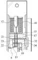
도 4는 도 1에 나타낸 전기 잠금장치의 락 상태 시 핀 챔버에서의 핀과 플런저의 위치를 설명하기 위한 도면이며, 도 5는 도 1에 나타낸 전기 잠금장치의 언락 상태 시 핀 챔버에서의 핀과 플런저의 위치를 설명하기 위한 도면이며, 도 6은 도 1에 나타낸 전기 잠금장치의 언락 상태이면서 데드볼트 회전 시 핀 챔버에서의 핀과 플런저의 위치를 설명하기 위한 도면이다.Figure 4 is a view for explaining the position of the pin and the plunger in the pin chamber in the locked state of the electric lock shown in Figure 1, Figure 5 is a pin in the pin chamber in the unlocked state of the electric lock shown in Figure 1 6 is a view for explaining the position of the plunger, Figure 6 is a view for explaining the position of the pin and plunger in the pin chamber during the dead bolt rotation while the unlocking state of the electric locking device shown in FIG.
우선, 종래 전기 잠금장치는 도 4에 나타낸 바와 같이 전기 잠금장치의 락킹을 위한 전원을 솔레노이드(11)에 공급하면 플런저(12)가 하부의 제 1 핀(21)을 누르게 되고, 제 1 핀(21)은 제 3 핀(23)을 누르게 되고, 제 3핀(23)은 하부의 제 2 핀(22)을 누르게 된다. 이때, 제 1 핀(21)은 제 1 챔버(17)와 제 3 챔버(34) 내부까지 들어가게 된다. 그에 따라 샤프트(6)에 고정되어 회동하도록 된 데드볼트(3)의 회동편(32)은 제 1 핀(21)에 걸려 회동하지 못하게 되어 전기 잠금장치가 락킹 상태를 유지하도록 한다.First, in the conventional electric lock device, as shown in FIG. 4, when the power supply for locking the electric lock device is supplied to the
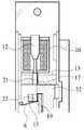
그러나 반대로 전기 잠금장치의 언락킹을 위해 전원을 차단하면, 도 5에 나타낸 바와 같이, 플런저(12)는 하우징(1)에 마련된 판 스프링(8)이 제 2 핀(22)을 밀어 올리고, 제 2 핀(22)이 밀어 올려짐에 따라 차례로 밀어 올려지는 제 3 핀(23) 및 제 1 핀(21)이 각각의 챔버(17)(34)(19)내에 위치하게 된다. 그에 따라 그에 따라 샤프트(6)에 고정되어 회동하도록 된 데드볼트(3)의 회동편(32) 역시 도 6에 나타낸 바와 같이 회동가능하게 된다.On the contrary, when the power is cut for unlocking the electric lock, as shown in FIG. 5, the
이때 데드볼드(3)의 회동편(32)이 회동하게 되면, 도 6에 나타낸 바와 같이 제 1 핀(21)이 제 1 챔버(17)에서 분리될 수 있었다. 따라서, 그와 같은 문제를 방지하기 위하여 회동편(32)중 제 1 핀(21) 하부에 위치하는 회동편(32)의 일부분이 제 1 핀(21)의 하부를 받치도록 하고 있다. 다시 말하면 회동편(32)의 일부분이 필수적으로 제 1 핀(21)의 하부를 받치는 구조를 갖고 있어야 한다.At this time, when the
참고로, 제 1 핀(21)의 경우 외부에서 강제적으로 문을 열고자 하는 경우 약 1톤(ton)의 압력까지 견딜 수 있도록 구성되기는 한다.For reference, the
그러나 이와 같은 종래 전기 잠금장치에 있어서는 도 4에 나타낸 바와 같은 전기 잠금장치 락킹 시 외부에서 전기 잠금장치의 언락킹 동작 전에 미리 도어를 열려고 하거나, 외부에서 강제로 침입하고자 하는 경우 회동편에 의해 제 1 핀이 계속해서 충격을 받게 된다.However, in such a conventional electric lock device, when the electric lock device locks as shown in FIG. The pin will continue to be shocked.
이와 같은 문제는 시간이 경과함에 따라 더욱 심해지는 것으로, 고의이던, 실수이던 간에 제 1 핀에는 계속적인 충격이 가해지게 된다. 이러한 문제는 결국 제 1 핀은 물론 회동편 및 도어 프레임 모두에 압력으로 이어지고, 그에 따라 전기 잠금장치의 하우징이나 및 도어 프레임 모두 변형되거나 파손될 수 있는 문제가 있었다.This problem is exacerbated over time, and the first pin is subjected to continuous impacts, whether intentional or mistaken. This problem eventually leads to pressure not only on the first pin but also on the pivoting piece and the door frame, so that both the housing and the door frame of the electric lock can be deformed or broken.
따라서, 본 발명은 상기와 같은 종래 기술의 제반 단점과 문제점을 해결하기 위한 것으로, 본 발명은 고정수단으로 이용되는 핀과 플런저 및 하우징의 구조를 변경하여 잠금장치의 본체를 구성하는 하우징이나 도어 프레임의 변형이나 파손을 방지할 수 있는 전기 잠금장치를 제공함에 그 목적이 있다.Accordingly, the present invention is to solve all the disadvantages and problems of the prior art as described above, the present invention is to change the structure of the pin and plunger and the housing used as the fixing means to form a housing or door frame of the locking device An object of the present invention is to provide an electric locking device that can prevent deformation or breakage.
상기와 같은 목적을 달성하기 위한 본 발명은, 배면과 상측면 및 하측면이 개방되고, 일측면에는 락킹 수단을 장착하기 위한 개방구가 형성되며, 개방구를 통해 락킹 수단을 결합하기 위한 샤프트의 상측을 고정하기 위한 상측 샤프트 홀과, 도어 언락킹 시 락킹 부재가 위치하는 공간부가 형성된 고정편과, 샤프트의 하측을 고정하기 위한 하측 샤프트 홀이 형성된 샤프트 고정돌기가 배면내부에 형성된 하우징; 하우징의 개방된 상측면에 안치되는 솔레노이드 케이스; 솔레노이드 케이스 내부에 구성된 중공의 솔레노이드; 솔레노이드 중공부분에 솔레노이드의 구동에 따라 상하운동하는 락킹 부재; 및, 하우징의 개방부를 통해 전면에 노출되는 암부재와, 하우징의 락킹 부재 공간부와 동일한 위치에 도어 락킹 시 락킹 부재가 위치하는 락킹 수단 공간부가 일측에 형성된 회동편이 형성된 락킹 수단; 을 포함하여 구성됨을 특징으로 하는 전기 잠금장치를 제공한다.The present invention for achieving the above object, the back and the upper side and the lower side is open, one side is formed with an opening for mounting the locking means, the shaft for coupling the locking means through the opening A housing having an upper shaft hole for fixing the upper side, a fixing piece having a space portion in which the locking member is positioned when the door is unlocked, and a shaft fixing protrusion having a lower shaft hole for fixing the lower side of the shaft; A solenoid case placed on an open upper side of the housing; A hollow solenoid configured inside the solenoid case; A locking member vertically moving in accordance with the driving of the solenoid to the solenoid hollow portion; And a locking means including a arm member exposed to the front surface through the opening of the housing, and a rotating piece having a locking means space portion at one side of which the locking member is located at the same time as the locking member space portion of the housing. It provides an electric lock, characterized in that configured to include.
여기서, 하우징 상측면과 하측면에는 하우징을 도어 프레임에 고정하기 위한 하우징 스크류 홀이 각각 형성되고, 하우징 일측면에는 솔레노이드 케이스를 하우징에 나사 결합하기 위한 결합 홀이 구성됨이 바람직하다.Here, the housing screw holes for fixing the housing to the door frame are formed on the upper and lower surfaces of the housing, respectively, and a coupling hole for screwing the solenoid case to the housing is formed on one side of the housing.
그리고, 솔레노이드 케이스의 일측면에는 하우징과 나사 결합되는 결합 홈 또는 결합 홀이 형성되고, 솔레노이드 케이스 하부에는 락킹 부재가 락킹 또는 언락킹을 위해 이동하기 위한 이동 홀이 형성됨이 바람직하다.In addition, one side of the solenoid case is preferably formed with a coupling groove or a coupling hole screwed to the housing, the lower portion of the solenoid case is preferably formed with a movement hole for moving the locking member for locking or unlocking.
또한, 락킹 부재는 솔레노이드에 위치하는 상부 락킹 부재와 락킹 수단의 락킹 또는 언락킹을 위해 락킹 수단 공간부에 위치하거나 고정편의 공간부에 위치하는 하부 락킹 부재 및 상부 락킹 부재와 하부 락킹 부재를 연결하는 연결 부재로 구성된 것이 바람직하다.Further, the locking member connects the upper locking member located in the solenoid and the lower locking member located in the locking means space or the space locking part for locking or unlocking the locking means and connecting the upper locking member and the lower locking member. It is preferable that it is comprised with a connection member.
한편, 락킹 부재의 하부 락킹 부재 중 락킹 수단의 락킹 수단 공간부에 위치하는 부분은 측면으로 30°내지 60°기울기를 갖는 경사면을 갖도록 구성된 것이 바람직하다.On the other hand, the portion of the lower locking member of the locking member located in the locking means space portion of the locking means is preferably configured to have an inclined surface having a slope of 30 ° to 60 ° to the side.
여기서, 상부 락킹 부재와 하부 락킹 부재는 각각 원통형 또는 사각형 중 하나의 형상을 갖도록 구성된 것이 바람직하다.Here, it is preferable that the upper locking member and the lower locking member are configured to have one of cylindrical or quadrangular shapes, respectively.
그리고, 상부 락킹 부재의 직경은 이동 홀의 직경보다 크게 구성됨이 바람직하다.And, the diameter of the upper locking member is preferably configured to be larger than the diameter of the moving hole.
한편, 락킹 수단의 회동편 중 하우징의 고정편에 인접한 회동편에는 고정편의 상측 샤프트 홀과 동일한 위치에 샤프트를 통과시키기 위한 락킹 수단 상측 샤프트 홀이 형성되고, 회동편의 하부에는 하우징의 하측 샤프트 홀과 동일한 위치에 샤프트를 통과시키기 위한 락킹 수단 하측 샤프트 홀이 형성된 고정 돌기가 구성됨이 바람직하다.On the other hand, among the rotating pieces of the locking means, the rotating piece adjacent to the fixing piece of the housing is formed with an upper shaft hole of the locking means for passing the shaft at the same position as the upper shaft hole of the fixing piece, and the lower shaft hole of the housing is provided below the rotating piece. It is preferable that a fixing projection having a locking means lower shaft hole for passing the shaft at the same position is formed.
여기서, 샤프트는 하우징의 상측 샤프트 홀과 락킹 수단의 상측 샤프트 홀을 통해 하측 샤프트 홀까지 구성되는 상측 샤프트와, 하우징의 하측 샤프트 홀을 통해 락킹 수단의 하측 샤프트 홀까지 구성되는 하측 샤프트로 구성되거나, 상측 샤프트 홀을 통해 하측 샤프트 홀에 삽입되거나, 하측 샤프트 홀을 통해 상측 샤프트 홀로 샤프트를 삽입되는 일체형으로 구성됨이 바람직하다.Here, the shaft is composed of an upper shaft configured to the lower shaft hole through the upper shaft hole of the housing and the upper shaft hole of the locking means, and a lower shaft configured to the lower shaft hole of the locking means through the lower shaft hole of the housing, It is preferable that it is configured to be integrally inserted into the lower shaft hole through the upper shaft hole, or the shaft is inserted into the upper shaft hole through the lower shaft hole.
한편, 샤프트 중 상측 샤프트 홀 삽입 부분과, 하측 샤프트 홀 삽입 부분은 나사로 구성됨이 바람직하다.On the other hand, the upper shaft hole insertion portion and the lower shaft hole insertion portion of the shaft is preferably composed of a screw.
그리고, 솔레노이드는 언락킹 시 락킹 부재가 락킹 수단의 공간부에서 고정편의 공간부로 이동하도록 권선됨이 바람직하다.In addition, the solenoid is preferably wound so that the locking member moves from the space portion of the locking means to the space portion of the fixing piece during unlocking.
상기와 같은 본 발명에 의하면 다음과 같은 효과가 있다.According to the present invention as described above has the following effects.
첫째, 고정수단으로 핀과 플런저 대신 일체형의 고정부재를 이용함으로써 잠금장치의 구조를 단순화할 수 있다.First, the structure of the locking device can be simplified by using an integral fixing member instead of the pin and the plunger as the fixing means.
둘째, 고정부재에 경사면을 갖도록 하여 비정상상태에서 전기 잠금장치의 락킹을 시도하는 경우 고정부재에 가해지는 압력을 분산시켜 하우징이나 도어 프레임의 변형이나 파손을 최소화할 수 있는 효과가 있다.Second, when the locking member has an inclined surface and attempts to lock the electric locking device in an abnormal state, the pressure applied to the fixing member may be dispersed to minimize deformation or breakage of the housing or door frame.
이하 본 발명에 따른 전기 잠금장치의 바람직한 실시예를 첨부된 도면을 참조하여 상세히 설명하기로 한다.Hereinafter, a preferred embodiment of the electric locking device according to the present invention will be described in detail with reference to the accompanying drawings.
아울러, 본 발명에서 사용되는 용어는 가능한 한 현재 널리 사용되는 일반적인 용어를 선택하였으나, 특정한 경우는 출원인이 임의로 선정한 용어도 있으며 이 경우는 해당되는 발명의 설명부분에서 상세히 그 의미를 기재하였으므로, 단순한 용어의 명칭이 아닌 용어가 가지는 의미로서 본 발명을 파악하여야 함을 밝혀두고자 한다.In addition, the terminology used in the present invention was selected as a general term that is widely used at present, but in certain cases, the term is arbitrarily selected by the applicant, and in this case, since the meaning is described in detail in the corresponding part of the present invention, a simple term It is to be understood that the present invention is to be understood as a meaning of terms rather than names.
또한 실시예를 설명함에 있어서 본 발명이 속하는 기술 분야에 익히 알려져 있고, 본 발명과 직접적으로 관련이 없는 기술 내용에 대해서는 설명을 생략한다. 이는 불필요한 설명을 생략함으로써 본 발명의 요지를 흐리지 않고 더욱 명확히 전달하기 위함이다.Further, in describing the embodiments, descriptions of technical contents which are well known in the technical field to which the present invention belongs and which are not directly related to the present invention will be omitted. This is to more clearly communicate without obscure the subject matter of the present invention by omitting unnecessary description.
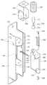
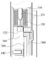
도 7은 본 발명에 따른 전기 잠금장치의 분해 사시도이다.7 is an exploded perspective view of the electric locking device according to the present invention.
본 발명에 따른 전기 잠금장치는 도 7에 나타낸 바와 같이, 전기 잠금장치의 몸체를 이루는 하우징(100)과, 하우징(100)에 장착되며 좌우 회동하는 것에 따라 전기 잠금장치를 락킹 또는 언락킹시키는 락킹 수단(300)과, 하우징(100)에 안치되며 솔레노이드(220) 동작에 따라 락킹 수단(300)의 회동을 제어하는 락킹 부재(230)을 포함하여 구성된다.As shown in FIG. 7, the electric locking device according to the present invention includes a
여기서, 하우징(100)은, 배면과 상측면 및 하측면이 개방되며, 일측면에는 락킹 수단(300)을 장착하기 위한 개방구(110)가 형성된다. 그리고, 하우징(100) 배면 상부 소정영역에는 락킹 수단(300)을 하우징(100)에 결합하기 위한 샤프트(400)를 고정하기 위한 상측 샤프트 홀(121)과, 도어 락킹 시 락킹 부재(230)의 하부가 위치하는 공간부(122)를 갖는 고정편(120)이 형성된다. 또한, 하우징(100) 하부 소정영역에는 하측 샤프트 홀(131)이 형성된 샤프트 고정돌기(130)가 배면내부에 형성된다.Here, the
또한 하우징(100)의 정면에는 래치(140)가 구성되어 있다.In addition, the
그리고, 하우징(100) 상측면과 하측면에는 하우징(100)을 도어 프레임에 고정하기 위한 하우징 스크류 홀(150)이 형성된다. 또한, 하우징(100) 측면 중 솔레노이드 케이스(210)와 인접한 부분에는 솔레노이드 케이스(210)를 하우징(100)에 결합하기 위한 결합 홀(160)이 구성된다.In addition, a
하우징(100)의 개방된 상측면에는 하우징(100)의 결합 홀(160)을 통해 하우징(100)과 나사결합되는 솔레노이드 케이스(210)가 안치된다. 이를 위하여 솔레노이드 케이스(210)에도 하우징(100)의 결합홈(160)과 수평한 부분에 결합 홈(또는 결합 홀)(250)이 형성된다. 그리고 솔레노이드 케이스(210) 하부에는 락킹 부재(230)가 상하로 이동하기 위한 이동 홀(240)이 형성된다.On the open upper side of the
한편, 솔레노이드 케이스(210) 내부에는 중공의 솔레노이드(220)가 구성되며, 솔레노이드(220) 중공부분에는 솔레노이드(220)의 동작에 따라 상하운동하는 상측과 하측은 넓고 중간부분은 좁은 아령 형상의 락킹 부재(230)가 구성된다. 이와 같은 락킹 부재(230)는 도 8 내지 도 11에서와 같이 다양한 형상으로 구성할 수 있다.On the other hand, the
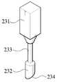
도 8 내지 도 11은 도 7에 나타낸 락킹 부재의 제 1 내지 제 4 실시예를 설명하기 위한 도면이다.8 to 11 are views for explaining the first to fourth embodiments of the locking member shown in FIG.
우선, 락킹 부재(230)는 기본적으로 상부 락킹 부재(231)와 하부 락킹 부재(232) 및 상부 락킹 부재(231)와 하부 락킹 부재(232)를 연결하는 연결 부재(233)로 구성된다.First, the locking
제 1 실시예를 나타낸 도 8을 보면, 상부 락킹 부재(231)는 원통형으로 구성되고, 하부 락킹 부재(232)는 마름모꼴로 구성된다. 이때, 하부 락킹 부재(232)는 평면적으로 보았을 때 일측면에 30°내지 60°기울기를 갖는 경사면(234)이 구성되어 있다. 이와 같은 경사면(234)은 락킹 수단(300) 회동 시 접촉되는 면으로써, 락킹 부재(230)에 가해지는 압력을 분산시킨다.Referring to FIG. 8 showing the first embodiment, the
제 2 실시예를 나타낸 도 9를 보면, 상부 락킹 부재(231)와 하부 락킹 부재(232) 모두 원통형으로 구성된다. 또한, 하부 락킹 부재(232)에 30°내지 60°기울기를 갖는 경사면(234)이 구성된다.Referring to FIG. 9 showing the second embodiment, both the
제 3 실시예를 나타낸 도 10을 보면, 상부 락킹 부재(231)는 사각형으로 구성되고, 하부 락킹 부재(232)는 원통형으로 구성된다. 이때, 하부 락킹 부재(2323)에 30°∼ 60°기울기를 갖는 경사면(234)이 구성되어 있다.Referring to FIG. 10 showing the third embodiment, the
제 4 실시예를 나타낸 도 11를 보면, 상부 락킹 부재(231)는 사각형으로 구성되고, 하부 락킹 부재(232)는 마름모꼴로 구성된다. 이때, 하부 락킹 부재(232)는 평면적으로 보았을 때 일측면에 30°∼60°기울기를 갖는 경사면(234)이 구성된다.Referring to FIG. 11 showing the fourth embodiment, the
제 1 내지 제 4 실시예에서, 하부 락킹 부재(232)의 경사면(234)은 락킹 수단(300) 회동 시 락킹 수단(300)과 접촉되는 면에 해당하는 부분이다. 이와 같은 하부 락킹 부재(232)의 경사면(234)은 비정상적으로 락킹 수단(300)이 회동되는 경우 락킹 수단(300)에 의한 압력을 분산시키는 효과가 있다. 따라서, 하우징이나 도어 프레임의 변형이나 파손을 방지할 수 있다.In the first to fourth embodiments, the
이때, 락킹 부재(230)는 상부 락킹 부재(231)를 솔레노이드(220)하부에서 상측으로 끼우고, 이동 홀(240)을 통해 솔레노이드(220)와 함께 솔레노이드 케이스(210)에 안치시킨다. 또한 상부 락킹 부재(231)의 직경은 이동 홀(240)의 직경 보다 크게 구성하여 잠금 장치의 락킹 시 락킹 부재(230)가 이동 홀(240)을 통해 솔레노이드 케이스(210)에 안착되도록 한다.In this case, the locking
한편, 락킹 수단(300)은 하우징(100) 전면에 노출되는 암부재(310)와, 하우징(100) 측면에서부터 내측으로 연장되어 형성된 회동편(320)으로 구성된다.On the other hand, the locking means 300 is composed of the
여기서, 회동편(320) 중 하우징(100)의 상측 고정편(120)에 인접한 상부의 회동편(320)에는 고정편(120)의 상측 샤프트 홀(121)과 동일한 위치에 샤프트(400)를 통과시키기 위한 락킹 수단 상측 샤프트 홀(330)이 형성된다.Here, the
그리고, 하우징(100)의 공간부(122)와 동일한 위치에는 락킹 부재(230)의 하부 락킹 부재(232)가 위치하는 락킹 수단 공간부(340)가 구성된 걸림턱부재(350)가 구성된다. 도어 락킹 시에는 걸림턱부재(350)와 하부 락킹 부재(232)에 걸림으로써 도어 락킹을 유지한다.And, at the same position as the
한편, 회동편(320)의 하부에는 하우징(100)의 하측 샤프트 홀(131)과 동일한 위치에 샤프트(400)를 통과시키기 위한 락킹 수단 하측 샤프트 홀(360)이 형성된 고정 돌기(370)가 구성된다.Meanwhile, a fixing
도 12a 및 도 12b는 도 7에 나타낸 샤프트의 제 1 실시예를 설명하기 위한 도면이고, 도 13은 도 7에 나타낸 샤프트의 제 2 실시예를 설명하기 위한 도면이다.12A and 12B are views for explaining the first embodiment of the shaft shown in FIG. 7, and FIG. 13 is a view for explaining the second embodiment of the shaft shown in FIG. 7.
샤프트(400)는 도 12a 및 도 12b에 나타낸 바와 같이 상측 샤프트(410)와 하 측 샤프트(420)로 구성할 수 있다. 다시 말하면, 상측 샤프트(410)는 하우징(100)의 상측 샤프트 홀(121)과 락킹 수단(300)의 상측 샤프트 홀(330)을 통해 하측 샤프트 홀(360)까지 구성된다. 한편, 하측 샤프트(420)는 하우징(100)의 하측 샤프트 홀(131)을 통해 락킹 수단(300)의 하측 샤프트 홀(360)까지 구성된다. 이를 위하여 하우징(100)의 상측 샤프트 홀(121)과 하측 샤프트 홀(131)은 각각 나사 홀로 구성한다. 또한, 상측 샤프트(410)의 상부 중 상측 샤프트 홀(121) 삽입 부분과, 하측 샤프트(420)의 하부 중 하측 샤프트 홀(131) 삽입 부분은 나사(411)(421)로 구성한다.The
샤프트(400)의 다른 실시예로는 도 13에 나타낸 바와 같이 상하측 샤프트(410,420)를 일체형으로 구성하는 것으로, 상측 샤프트 홀(121)을 통해 하측 샤프트 홀(131)에 삽입하거나, 하측 샤프트 홀(131)을 통해 상측 샤프트 홀(121)로 샤프트(400)를 삽입한다. 이때, 샤프트(400)에서 상측 샤프트 홀(121) 삽입 부분과, 하측 샤프트 홀(131) 삽입 부분은 나사(401)(402)로 구성한다.In another embodiment of the
한편, 스프링(500)은 락킹 수단(300)이 언락킹 된 후 자동으로 락킹될 수 있도록 토션 스프링으로 구성하는데, 샤프트(400)를 상측 샤프트 홀(330)이나 하측 샤프트 홀(360)에 일부 끼운 후, 스프링(500)을 샤프트(400)에 끼운다.On the other hand, the
도 14는 도 7에 나타낸 전기 잠금장치의 락 상태 시 락킹 부재의 위치를 설명하기 위한 도면이고, 도 15는 도 7에 나타낸 전기 잠금장치의 언락 상태 시 락킹 부재의 위치를 설명하기 위한 도면이며, 도 16은 도 7에 나타낸 전기 잠금장치의 언락 상태 시 핀 락킹 수단과 락킹 부재의 위치를 설명하기 위한 도면이다.14 is a view for explaining the position of the locking member in the locked state of the electric lock device shown in FIG. 7, FIG. 15 is a view for explaining the position of the locking member in the unlocked state of the electric lock device shown in FIG. FIG. 16 is a view for explaining the positions of the pin locking means and the locking member in the unlocked state of the electric locking device shown in FIG.
이와 같은 본 발명 전기 잠금장치의 동작을 첨부된 도 14 내지 도 16을 참조하여 설명한다.Such operation of the electric lock device of the present invention will be described with reference to FIGS. 14 to 16.
우선, 본 발명 전기 잠금장치는 도 14에 나타낸 바와 같이, 평상시에는 전기 잠금장치의 락킹을 위하여 솔레노이드(220)에 전원을 공급하지 않는다. 따라서, 락킹 부재(230)는 도어 락킹이 되도록 락킹 부재(230)의 하부 락킹 부재(232)가 락킹 수단 공간부(340)에 위치한다. 이때, 도 8 내지 도 11에서 설명한 바와 같이 락킹 수단(300)이 비정상적으로 회동하는 경우 락킹 수단(300)의 걸림턱 부재(350)가 락킹 수단 공간부(340)에 위치한 하부 락킹 부재(232)의 경사면과 접촉된다. 따라서, 잠금 장치는 락킹 상태를 유지하는 한편, 하우징이나 도어 프레임에 가해지는 락킹 수단(300)으로부터의 압력이 최대한 분산된다. 이때, 하부 락킹 부재(232)는 걸림턱 부재(350)의 뒤편에 위치한 것으로 점선으로 표시하였다.First, as shown in FIG. 14, the electric lock device of the present invention does not normally supply power to the
한편, 전기 잠금장치의 언락킹을 위해 전원을 공급하면, 도 15에 나타낸 바와 같이, 솔레노이드(220)에 전류가 흘러 자기장이 형성된다. 이때, 솔레노이드(220)는 철성분이 포함된 락킹 부재(230)가 락킹을 위한 위치로 이동할 수 있도록 솔레노이드 도선을 구성(권선)하거나 전원을 반대로 공급한다.On the other hand, when power is supplied for unlocking the electric locking device, as shown in FIG. 15, current flows in the
따라서, 언락킹 시 락킹 부재(230)의 하부 락킹 부재(232)는 락킹 수단 공간부(340)에서 고정편(120)의 공간부(122)로 이동한다. 그에 따라 락킹 수단(300)은 회동 가능한 상태가 된다.Therefore, when unlocking, the
이어, 도 16에 나타낸 바와 같이 락킹 수단(300)을 회동시켜 도어를 열수 있 게 된다. 이때 걸림턱 부재(350)는 하우징 내측으로 이동하여 도면상에 표시되지 않았으며, 공간부(350)가 완전히 노출되었다.Subsequently, as shown in FIG. 16, the door may be opened by rotating the locking means 300. At this time, the locking
이상과 같은 예로 본 발명을 설명하였으나, 본 발명은 반드시 이러한 예들에 국한되는 것이 아니고, 본 발명의 기술사상을 벗어나지 않는 범위 내에서 다양하게 변형 실시될 수 있다. 따라서 본 발명에 개시된 예들은 본 발명의 기술 사상을 한정하기 위한 것이 아니라 설명하기 위한 것이고, 이러한 예들에 의하여 본 발명의 기술 사상의 범위가 한정되는 것은 아니다. 본 발명의 보호 범위는 아래의 청구범위에 의하여 해석되어야 하며, 그와 동등한 범위 내에 있는 모든 기술 사상은 본 발명의 권리범위에 포함되는 것으로 해석되어야 한다.Although the present invention has been described by way of example as described above, the present invention is not necessarily limited to these examples, and various modifications can be made without departing from the spirit of the present invention. Therefore, the examples disclosed in the present invention are not intended to limit the technical idea of the present invention but to explain the present invention, and the scope of the technical idea of the present invention is not limited by these examples. The scope of protection of the present invention should be interpreted by the following claims, and all technical ideas within the scope equivalent thereto should be construed as being included in the scope of the present invention.
도 1은 종래 기술에 따른 전기 잠금장치의 락 상태를 나타낸 사시도,1 is a perspective view showing a locked state of an electric locking device according to the prior art,
도 2는 도 1에 나타낸 전기 잠금장치의 언락 상태를 나타낸 사시도,Figure 2 is a perspective view showing an unlocked state of the electric locking device shown in FIG.
도 3은 도 1에 나타낸 전기 잠금장치의 분해 사시도,3 is an exploded perspective view of the electric locking device shown in FIG.
도 4는 도 1에 나타낸 전기 잠금장치의 락 상태 시 핀 챔버에서의 핀과 플런저의 위치를 설명하기 위한 도면,4 is a view for explaining the position of the pin and the plunger in the pin chamber in the locked state of the electric locking device shown in FIG.
도 5는 도 1에 나타낸 전기 잠금장치의 언락 상태 시 핀 챔버에서의 핀과 플런저의 위치를 설명하기 위한 도면,5 is a view for explaining the position of the pin and the plunger in the pin chamber in the unlocked state of the electric locking device shown in FIG.
도 6은 도 1에 나타낸 전기 잠금장치의 언락 상태 시 데드볼트의 회전에 따른 핀과 플런저의 위치를 설명하기 위한 도면,6 is a view for explaining the position of the pin and plunger according to the rotation of the dead bolt in the unlocked state of the electric lock device shown in FIG.
도 7은 본 발명에 따른 전기 잠금장치를 설명하기 위한 분해 사시도,7 is an exploded perspective view for explaining an electric lock device according to the present invention;
도 8 내지 도 11은 도 7에 나타낸 락킹 부재의 제 1 내지 제 4 실시예를 설명하기 위한 도면,8 to 11 are views for explaining the first to fourth embodiments of the locking member shown in FIG.
도 12a 및 도 12b는 도 7에 나타낸 샤프트의 제 1 실시예를 설명하기 위한 도면,12A and 12B are views for explaining a first embodiment of the shaft shown in FIG.
도 13은 도 7에 나타낸 샤프트의 제 2 실시예를 설명하기 위한 도면,FIG. 13 is a view for explaining a second embodiment of the shaft shown in FIG. 7;
도 14는 도 7에 나타낸 전기 잠금장치의 락 상태 시 락킹 부재의 위치를 설명하기 위한 도면,14 is a view for explaining the position of the locking member in the locked state of the electric locking device shown in FIG.
도 15는 도 7에 나타낸 전기 잠금장치의 언락 상태 시 락킹 부재의 위치를 설명하기 위한 도면,15 is a view for explaining the position of the locking member in the unlocked state of the electric locking device shown in FIG.
도 16은 도 7에 나타낸 전기 잠금장치의 언락 상태 시 락킹 수단과 락킹 부재의 위치를 설명하기 위한 도면이다.FIG. 16 is a view for explaining positions of the locking means and the locking member in the unlocked state of the electric locking device shown in FIG. 7.
*도면의 주요 부분에 대한 부호의 설명** Description of the symbols for the main parts of the drawings *
100 : 하우징110 : 개방구100
120 : 고정편121 : 상측 샤프트 홀120: fixed piece 121: upper shaft hole
122 : 공간부130 : 샤프트 고정돌기122: space 130: shaft fixing protrusion
131 : 하측 샤프트 홀140 : 래치131: lower shaft hole 140: latch
150 : 하우징 스크류 홀160 : 결합 홀150: housing screw hole 160: coupling hole
210 : 솔레노이드 케이스220 : 솔레노이드210: solenoid case 220: solenoid
230 : 락킹 부재240 : 이동 홀230: locking member 240: moving hole
250 : 결합 홈 300 : 락킹 수단250: coupling groove 300: locking means
310 : 암부재320 : 회동편310: arm member 320: rotating piece
330 : 락킹 수단 상측 샤프트 홀340 : 공간부330: upper shaft hole locking means 340: space portion
350 : 걸림턱 부재350: locking jaw member
360 : 락킹 수단 하측 샤프트 홀370 : 고정돌기360: locking means lower shaft hole 370: fixing protrusion
400, 410, 420 : 샤프트500 : 토션 스프링400, 410, 420: shaft 500: torsion spring
Claims (11)
Translated fromKoreanPriority Applications (1)
| Application Number | Priority Date | Filing Date | Title |
|---|---|---|---|
| KR1020090080401AKR101096462B1 (en) | 2009-08-28 | 2009-08-28 | Electric lock |
Applications Claiming Priority (1)
| Application Number | Priority Date | Filing Date | Title |
|---|---|---|---|
| KR1020090080401AKR101096462B1 (en) | 2009-08-28 | 2009-08-28 | Electric lock |
Publications (2)
| Publication Number | Publication Date |
|---|---|
| KR20110022902A KR20110022902A (en) | 2011-03-08 |
| KR101096462B1true KR101096462B1 (en) | 2011-12-21 |
Family
ID=43931103
Family Applications (1)
| Application Number | Title | Priority Date | Filing Date |
|---|---|---|---|
| KR1020090080401AExpired - Fee RelatedKR101096462B1 (en) | 2009-08-28 | 2009-08-28 | Electric lock |
Country Status (1)
| Country | Link |
|---|---|
| KR (1) | KR101096462B1 (en) |
Citations (2)
| Publication number | Priority date | Publication date | Assignee | Title |
|---|---|---|---|---|
| KR100825446B1 (en)* | 2006-09-06 | 2008-04-28 | 박영한 | Emergency locking release device of electronic door lock |
| KR100907047B1 (en)* | 2007-12-13 | 2009-07-09 | (주)이엘에스티 | Electronic Dead Bolt Door Lock |
- 2009
- 2009-08-28KRKR1020090080401Apatent/KR101096462B1/ennot_activeExpired - Fee Related
Patent Citations (2)
| Publication number | Priority date | Publication date | Assignee | Title |
|---|---|---|---|---|
| KR100825446B1 (en)* | 2006-09-06 | 2008-04-28 | 박영한 | Emergency locking release device of electronic door lock |
| KR100907047B1 (en)* | 2007-12-13 | 2009-07-09 | (주)이엘에스티 | Electronic Dead Bolt Door Lock |
Also Published As
| Publication number | Publication date |
|---|---|
| KR20110022902A (en) | 2011-03-08 |
Similar Documents
| Publication | Publication Date | Title |
|---|---|---|
| US8122746B2 (en) | Electromechanical cylinder plug | |
| CA2653935C (en) | Cam lock with retractable bolt | |
| KR101756565B1 (en) | Improved rotary blocking device | |
| US8419083B2 (en) | Electromechanical locks and latching arrangements | |
| CN101203650B (en) | Electromechanical lock device | |
| EP2480740B1 (en) | Lockable enclosure | |
| US9702167B2 (en) | Electric lock for doors | |
| RU2723831C2 (en) | Door lock with a rebate | |
| KR0137881B1 (en) | Locking device using card key | |
| US7392677B1 (en) | Lock core structure | |
| KR101096462B1 (en) | Electric lock | |
| US12227969B2 (en) | Door latch locking mechanism | |
| US6591644B2 (en) | Ball bearing cylinder plug and key retention | |
| KR100849524B1 (en) | Mortis and door lock device with him | |
| KR100387951B1 (en) | Auto re-locking type mortise locking system | |
| CN110939317B (en) | Control handle with entry monitoring system | |
| JP2003074226A (en) | Small electric power type door lock system | |
| CN108027195A (en) | Handle and freezer unit | |
| KR102425260B1 (en) | Dead Bolt Door Lock | |
| CN217380069U (en) | Flip type lock | |
| CN112240131B (en) | Mechanical emergency device of motor lock body and motor lock body | |
| KR101958314B1 (en) | Access Control System of Door with Panic Function | |
| KR20180105971A (en) | Key lock device for air circuit breaker | |
| KR20030025502A (en) | Door locking apparatus | |
| CN119421985A (en) | Swing handle arrangement with locking function |
Legal Events
| Date | Code | Title | Description |
|---|---|---|---|
| A201 | Request for examination | ||
| PA0109 | Patent application | St.27 status event code:A-0-1-A10-A12-nap-PA0109 | |
| PA0201 | Request for examination | St.27 status event code:A-1-2-D10-D11-exm-PA0201 | |
| D13-X000 | Search requested | St.27 status event code:A-1-2-D10-D13-srh-X000 | |
| D14-X000 | Search report completed | St.27 status event code:A-1-2-D10-D14-srh-X000 | |
| E902 | Notification of reason for refusal | ||
| PE0902 | Notice of grounds for rejection | St.27 status event code:A-1-2-D10-D21-exm-PE0902 | |
| PG1501 | Laying open of application | St.27 status event code:A-1-1-Q10-Q12-nap-PG1501 | |
| E13-X000 | Pre-grant limitation requested | St.27 status event code:A-2-3-E10-E13-lim-X000 | |
| P11-X000 | Amendment of application requested | St.27 status event code:A-2-2-P10-P11-nap-X000 | |
| P13-X000 | Application amended | St.27 status event code:A-2-2-P10-P13-nap-X000 | |
| E701 | Decision to grant or registration of patent right | ||
| PE0701 | Decision of registration | St.27 status event code:A-1-2-D10-D22-exm-PE0701 | |
| GRNT | Written decision to grant | ||
| PR0701 | Registration of establishment | St.27 status event code:A-2-4-F10-F11-exm-PR0701 | |
| PR1002 | Payment of registration fee | St.27 status event code:A-2-2-U10-U11-oth-PR1002 Fee payment year number:1 | |
| PG1601 | Publication of registration | St.27 status event code:A-4-4-Q10-Q13-nap-PG1601 | |
| FPAY | Annual fee payment | Payment date:20150114 Year of fee payment:4 | |
| PR1001 | Payment of annual fee | St.27 status event code:A-4-4-U10-U11-oth-PR1001 Fee payment year number:4 | |
| PR1001 | Payment of annual fee | St.27 status event code:A-4-4-U10-U11-oth-PR1001 Fee payment year number:5 | |
| FPAY | Annual fee payment | Payment date:20161213 Year of fee payment:6 | |
| PR1001 | Payment of annual fee | St.27 status event code:A-4-4-U10-U11-oth-PR1001 Fee payment year number:6 | |
| P22-X000 | Classification modified | St.27 status event code:A-4-4-P10-P22-nap-X000 | |
| PR1001 | Payment of annual fee | St.27 status event code:A-4-4-U10-U11-oth-PR1001 Fee payment year number:7 | |
| LAPS | Lapse due to unpaid annual fee | ||
| PC1903 | Unpaid annual fee | St.27 status event code:A-4-4-U10-U13-oth-PC1903 Not in force date:20181215 Payment event data comment text:Termination Category : DEFAULT_OF_REGISTRATION_FEE | |
| PC1903 | Unpaid annual fee | St.27 status event code:N-4-6-H10-H13-oth-PC1903 Ip right cessation event data comment text:Termination Category : DEFAULT_OF_REGISTRATION_FEE Not in force date:20181215 |