KR101096401B1 - Surgical instruments - Google Patents
Surgical instrumentsDownload PDFInfo
- Publication number
- KR101096401B1 KR101096401B1KR1020090036479AKR20090036479AKR101096401B1KR 101096401 B1KR101096401 B1KR 101096401B1KR 1020090036479 AKR1020090036479 AKR 1020090036479AKR 20090036479 AKR20090036479 AKR 20090036479AKR 101096401 B1KR101096401 B1KR 101096401B1
- Authority
- KR
- South Korea
- Prior art keywords
- body portion
- surgical instrument
- suction
- optical fiber
- suction port
- Prior art date
- Legal status (The legal status is an assumption and is not a legal conclusion. Google has not performed a legal analysis and makes no representation as to the accuracy of the status listed.)
- Expired - Fee Related
Links
Images


Classifications
- A—HUMAN NECESSITIES
- A61—MEDICAL OR VETERINARY SCIENCE; HYGIENE
- A61B—DIAGNOSIS; SURGERY; IDENTIFICATION
- A61B17/00—Surgical instruments, devices or methods
- A61B17/02—Surgical instruments, devices or methods for holding wounds open, e.g. retractors; Tractors
- A61B17/0206—Surgical instruments, devices or methods for holding wounds open, e.g. retractors; Tractors with antagonistic arms as supports for retractor elements
- A—HUMAN NECESSITIES
- A61—MEDICAL OR VETERINARY SCIENCE; HYGIENE
- A61B—DIAGNOSIS; SURGERY; IDENTIFICATION
- A61B17/00—Surgical instruments, devices or methods
- A61B17/02—Surgical instruments, devices or methods for holding wounds open, e.g. retractors; Tractors
- A—HUMAN NECESSITIES
- A61—MEDICAL OR VETERINARY SCIENCE; HYGIENE
- A61B—DIAGNOSIS; SURGERY; IDENTIFICATION
- A61B17/00—Surgical instruments, devices or methods
- A61B17/28—Surgical forceps
- A61B17/2812—Surgical forceps with a single pivotal connection
- A—HUMAN NECESSITIES
- A61—MEDICAL OR VETERINARY SCIENCE; HYGIENE
- A61M—DEVICES FOR INTRODUCING MEDIA INTO, OR ONTO, THE BODY; DEVICES FOR TRANSDUCING BODY MEDIA OR FOR TAKING MEDIA FROM THE BODY; DEVICES FOR PRODUCING OR ENDING SLEEP OR STUPOR
- A61M27/00—Drainage appliance for wounds or the like, i.e. wound drains, implanted drains
- A—HUMAN NECESSITIES
- A61—MEDICAL OR VETERINARY SCIENCE; HYGIENE
- A61B—DIAGNOSIS; SURGERY; IDENTIFICATION
- A61B90/00—Instruments, implements or accessories specially adapted for surgery or diagnosis and not covered by any of the groups A61B1/00 - A61B50/00, e.g. for luxation treatment or for protecting wound edges
- A61B90/30—Devices for illuminating a surgical field, the devices having an interrelation with other surgical devices or with a surgical procedure
- A61B2090/306—Devices for illuminating a surgical field, the devices having an interrelation with other surgical devices or with a surgical procedure using optical fibres
- A—HUMAN NECESSITIES
- A61—MEDICAL OR VETERINARY SCIENCE; HYGIENE
- A61B—DIAGNOSIS; SURGERY; IDENTIFICATION
- A61B2217/00—General characteristics of surgical instruments
- A61B2217/002—Auxiliary appliance
- A61B2217/005—Auxiliary appliance with suction drainage system
- A—HUMAN NECESSITIES
- A61—MEDICAL OR VETERINARY SCIENCE; HYGIENE
- A61M—DEVICES FOR INTRODUCING MEDIA INTO, OR ONTO, THE BODY; DEVICES FOR TRANSDUCING BODY MEDIA OR FOR TAKING MEDIA FROM THE BODY; DEVICES FOR PRODUCING OR ENDING SLEEP OR STUPOR
- A61M1/00—Suction or pumping devices for medical purposes; Devices for carrying-off, for treatment of, or for carrying-over, body-liquids; Drainage systems
- A61M1/84—Drainage tubes; Aspiration tips
Landscapes
- Health & Medical Sciences (AREA)
- Life Sciences & Earth Sciences (AREA)
- Surgery (AREA)
- Animal Behavior & Ethology (AREA)
- Heart & Thoracic Surgery (AREA)
- Biomedical Technology (AREA)
- Engineering & Computer Science (AREA)
- General Health & Medical Sciences (AREA)
- Public Health (AREA)
- Veterinary Medicine (AREA)
- Medical Informatics (AREA)
- Nuclear Medicine, Radiotherapy & Molecular Imaging (AREA)
- Molecular Biology (AREA)
- Ophthalmology & Optometry (AREA)
- Anesthesiology (AREA)
- Otolaryngology (AREA)
- Hematology (AREA)
- Surgical Instruments (AREA)
Abstract
Translated fromKorean
Description
Translated fromKorean본 발명은 수술 기구에 관한 것으로, 더욱 상세하게는 환자의 생체 조직을 박리하는 등의 수술에 사용하는 수술 기구에 관한 것이다.The present invention relates to a surgical instrument, and more particularly, to a surgical instrument used for surgery, such as peeling off the biological tissue of the patient.
일반적으로 외과 수술 중에는 연부 조직(soft tissue)을 박리(dissetion)하여 수술자(operator)가 원하는 수술 시야로 진입을 해야 하는 경우가 많다. 하지만 생체 조직은 모두 혈액공급을 받으면서 생존을 하기 때문에 어떤 조직이든, 조직 박리를 시행하게 되면 출혈이 발생하게 된다. 그렇게 되면 출혈이 발생한 부위를 지혈하기 위해서 이미 출혈된 또는 출혈 중인 혈액을 수술보조자(assistant)가 흡입기로 신속히 제거해서 출혈부위를 확인한 후 수술자가 지혈을 시행해야 된다. 지혈이 완료되면 수술자는 원하는 수술 시야로 진행을 위해 더 깊은 조직으로 박리를 시행하게 된다. 그러면 또 다시 출혈이 시작되어 수술자와 수술보조자는 같은 작업을 반복하게 되고, 조직 박리 수술 시야가 깊어지게 되면, 출혈뿐만 아니라 열악한 조명 환경을 접하게 된다. 이는 수술 시야가 깊어지면 수술실 천장에 달려있는 무영등(수술조명등)의 불빛이 수술 시야에 도달할 수 없게 되기 때문이다. 결과적으로, 조직 박리의 심도가 깊어질수록 출혈과 열악한 조명 때문에 수술자는 수술의 어려움을 겪는 경우가 많고 신속한 지혈이 어려워 수술 중 환자의 출혈량이 많아지게 되고, 수술 시간이 길어지며, 최악의 경우에는 열악한 시야 때문에 수술의 목적과 관련이 없는 중요한 타 장기의 손상을 유발할 수 있다. 이러한 결과들은 환자에게 수술 후 합병증이나 사망률을 증가시키는 원인이 된다.In general, during surgery, soft tissues are often detached to enter the desired surgical field of view by the operator. However, since all living tissues survive by receiving blood supply, bleeding occurs when any tissue is detached. Then, in order to bleed the site of bleeding, the bleeding or bleeding blood must be removed by the surgical assistant (assistant) with an inhaler, and the bleeding site must be checked by the operator. Once hemostasis is complete, the operator will need to detach the deeper tissue to advance to the desired surgical field of view. Then, the bleeding begins again and the operator and the surgical assistant repeats the same operation, and when the tissue detachment surgery becomes deeper, the bleeding as well as the poor lighting environment. This is because when the field of view becomes deeper, the light of the shadowless light on the ceiling of the operating room cannot reach the field of view. As a result, the deeper the depth of tissue detachment, the more bleeding and poor illumination the operator has, the more difficult the operation is, the faster hemostasis is difficult, resulting in more bleeding of the patient during surgery, longer operation times, and in the worst case, Poor visual field can cause damage to other vital organs that are irrelevant to the purpose of the surgery. These results may cause increased postoperative complications and mortality in patients.
본 발명은 상기와 같은 문제점을 해결하기 위하여 안출된 것으로서, 환자의 생체 조직 수술 시 어둡고 심도가 깊은 수술 부위에서 발생하는 출혈을 흡입하고 조명을 비추어 수술 부위의 시야를 확보함으로써 수술자가 안전하고 신속한 수술을 할 수 있도록 하는 수술 기구를 제공하는데 그 목적이 있다.The present invention has been made in order to solve the above problems, by inhaling the bleeding occurring in the dark and deep surgery area during surgery of the patient's biological tissue and by illuminating the operator to secure the field of view of the surgical site to operate safely and promptly The purpose is to provide a surgical instrument that allows.
본 발명의 목적들은 이상에서 언급한 목적들로 제한되지 않으며, 언급되지 않은 또 다른 목적들은 아래의 기재로부터 당업자에게 명확하게 이해되어질 수 있을 것이다.The objects of the present invention are not limited to the above-mentioned objects, and other objects not mentioned can be clearly understood by those skilled in the art from the following description.
상기 목적을 달성하기 위한 본 발명의 바람직한 실시예에 따른 수술 기구는, 선단에 흡입구가 적어도 하나 형성되는 제 1 몸체부, 상기 제 1 몸체부와 교차되어 회전 가능하게 결합되는 제 2 몸체부, 수술 중 환자의 출혈 부위에서 발생하는 혈액을 상기 흡입구를 통해 흡입하기 위해 상기 제 1 몸체부에 구비되는 흡입부, 및 상기 제 1 몸체부와 상기 제 2 몸체부의 선단 사이를 조명하기 위해 상기 제 2 몸체부에 구비되는 조명부를 포함할 수 있다.Surgical instrument according to a preferred embodiment of the present invention for achieving the above object, the first body portion formed with at least one suction port at the tip, the second body portion is rotatably coupled to the first body portion, surgery A suction part provided in the first body part to suck blood generated at the bleeding site of the patient through the suction port, and the second body to illuminate between the tip of the first body part and the second body part. It may include a lighting unit provided in the unit.
또한, 상기 흡입부는 상기 흡입구와 연결되도록 상기 제 1 몸체부에 내장되는 흡입관을 포함할 수 있다.In addition, the suction unit may include a suction tube embedded in the first body to be connected to the suction port.
또한, 상기 제 1 몸체부의 내부에는 상기 흡입관이 삽입되어 내장될 수 있도록 흡입관 삽입홀이 길이방향으로 길게 형성되는 것이 바람직하다.In addition, it is preferable that the suction pipe insertion hole is formed to be long in the longitudinal direction so that the suction pipe is inserted into the first body.
또한, 상기 흡입구의 직경은 상기 흡입관 삽입홀의 직경보다 작게 형성되는 것이 바람직하다.In addition, the diameter of the suction port is preferably formed smaller than the diameter of the suction pipe insertion hole.
또한, 상기 흡입구는 상기 제 1 몸체부의 선단 전면 또는 내측면에 형성되는 것이 바람직하다.In addition, the suction port is preferably formed on the front end or the inner surface of the first body portion.
또한, 상기 조명부는 상기 제 2 몸체부에 내장되며, 광원에서 발생하는 광을 광 전송하여 상기 제 1 몸체부와 상기 제 2 몸체부의 선단 사이를 조사하도록 가이드 하는 광섬유를 포함할 수 있다. 여기서, 상기 광원은 LED인 것이 바람직하다.In addition, the lighting unit may be embedded in the second body portion, and may include an optical fiber for guiding the light emitted from the light source to guide the irradiation between the tip of the first body portion and the second body portion. Here, the light source is preferably an LED.
또한, 상기 제 2 몸체부의 내부에는 상기 광섬유가 삽입되어 내장될 수 있도록 광섬유 삽입홀이 길이방향으로 길게 형성될 수 있다.In addition, the optical fiber insertion hole may be formed long in the longitudinal direction so that the optical fiber is inserted into the second body.
또한, 상기 제 2 몸체부에는 상기 광섬유의 선단이 노출되는 조명구가 적어도 하나 형성될 수 있으며, 상기 조명구는 상기 제 2 몸체부의 선단으로부터 후방으로 일정거리 이격되어 내측면에 형성되는 것이 바람직하다.In addition, the second body portion may be formed with at least one lighting tool exposed the front end of the optical fiber, the lighting tool is preferably formed on the inner side spaced apart a predetermined distance from the rear end of the second body portion.
또한, 상기 조명구에 노출된 상기 광섬유는 상기 제 1 몸체부의 선단과 상기 제 2 몸체부의 선단이 벌어진 사이의 중앙 부위를 조명하도록 배치되는 것이 바람직하다.In addition, the optical fiber exposed to the lighting fixture is preferably arranged to illuminate the central portion between the leading end of the first body portion and the leading end of the second body portion.
또한, 상기 조명부는 상기 제 1 몸체부의 선단과 상기 제 2 몸체부의 선단이 벌어진 사이의 중앙 부위를 조명하도록 상기 제 2 몸체부의 선단으로부터 후방으로 일정거리 이격되어 내측면에 구비되는 전구 또는 LED 램프인 것이 바람직하다.The lighting unit may be a light bulb or an LED lamp provided on an inner side of the first body unit at a predetermined distance from the front end of the second body unit to illuminate a central portion between the front end of the first body unit and the front end of the second body unit. It is preferable.
또한, 상기 제 1 및 제 2 몸체부의 선단은 상향 또는 하향으로 벤딩되게 형성되는 것이 바람직하다.In addition, the front end of the first and second body portion is preferably formed to be bent upwards or downwards.
또한, 상기 제 1 및 제 2 몸체부의 후단에는 손가락을 끼워 파지할 수 있도록 손잡이부가 형성될 수 있다.In addition, a handle portion may be formed at a rear end of the first and second body parts so as to grip and hold a finger.
또한, 상기 제 1 몸체부와 상기 제 2 몸체부는 회전결합부에 의해 회전 가능하게 결합될 수 있다. 여기서, 상기 회전결합부는, 상기 제 1 몸체부의 중앙 부위에 일체로 형성되며 일면의 가장자리부에 한 쌍의 결합돌기가 형성되는 제 1 회전결합부, 및 상기 제 2 몸체부의 중앙 부위에 일체로 형성되며 상기 제 1 회전결합부의 일면과 대향되는 면의 가장자리부에 상기 한 쌍의 결합돌기가 끼워져 일정 회전 각도의 범위 내에서 회전 가능하게 결합되는 한 쌍의 결합홈이 형성되는 제 2 회전결합부를 포함할 수 있다.In addition, the first body portion and the second body portion may be rotatably coupled by a rotation coupling portion. Here, the rotary coupling portion is formed integrally with the central portion of the first body portion, the first rotary coupling portion is formed integrally with the central portion of the second body portion and a pair of coupling projections formed on the edge of one surface And a second rotary coupling part having a pair of coupling grooves formed to be rotatably coupled within a range of a predetermined rotation angle by inserting the pair of coupling protrusions at an edge portion of the surface opposite to one surface of the first rotary coupling portion. can do.
본 발명의 수술 기구는, 선단에 흡입구가 적어도 하나 형성되는 제 1 몸체부, 상기 제 1 몸체부와 교차되어 회전 가능하게 결합되며 선단에 조명구가 적어도 하나 형성되는 제 2 몸체부, 수술 중 환자의 출혈 부위에서 발생하는 혈액을 상기 흡입구를 통해 흡입하기 위해 상기 제 1 몸체부에 내장되는 흡입관, 상기 조명구를 통해 상기 제 1 몸체부와 상기 제 2 몸체부의 선단 사이를 조명하기 위해 상기 제 2 몸체부에 내장되는 광섬유, 상기 흡입관에 흡입력을 제공하는 흡입장치, 및 상기 광섬유에 광을 제공하는 광원을 포함할 수 있다.Surgical instruments of the present invention, the first body portion having at least one suction port is formed on the front end, the second body portion is rotatably coupled to the first body portion and the at least one lighting fixture is formed on the front end of the patient during surgery A suction tube embedded in the first body portion to suck blood generated at the bleeding portion through the suction hole, and the second body portion to illuminate between the tip of the first body portion and the second body portion through the lighting fixture. It may include an optical fiber embedded in, a suction device for providing a suction force to the suction pipe, and a light source for providing light to the optical fiber.
기타 실시예들의 구체적인 사항들은 상세한 설명 및 도면들에 포함되어 있다.Specific details of other embodiments are included in the detailed description and the drawings.
상기한 바와 같은 본 발명의 수술 기구에 따르면, 수술 시 어둡고 출혈이 많 은 조직을 박리할 때 수술 부위에서 발생하는 출혈을 흡입하고 조명을 비추어 조직 박리의 심도가 깊은 수술 부위의 시야를 확보할 수 있게 됨으로써, 수술자는 안전하고 신속한 수술을 할 수 있다.According to the surgical instrument of the present invention as described above, when bleeding dark and bleeding tissue during surgery, the bleeding occurring at the surgical site is inhaled and illuminated to secure a field of view of the surgical site with a deep depth of tissue detachment By doing so, the operator can perform a safe and rapid operation.
또한, 전체적으로 소형의 수술 기구에 조직 박리, 출혈 흡입 및 조명 기능과 같은 3가지 기능을 갖출 수 있도록 제작하여 사용상 편리성을 제공한다.In addition, it provides convenience in use by making it possible to have three functions, such as tissue detachment, bleeding suction and lighting function to the overall small surgical instruments.
본 발명의 효과들은 이상에서 언급한 효과들로 제한되지 않으며, 언급되지 않은 또 다른 효과들은 청구범위의 기재로부터 당업자에게 명확하게 이해될 수 있을 것이다.The effects of the present invention are not limited to the above-mentioned effects, and other effects not mentioned will be clearly understood by those skilled in the art from the description of the claims.
본 발명의 이점 및 특징, 그리고 그것들을 달성하는 방법은 첨부되는 도면과 함께 상세하게 후술되어 있는 실시 예들을 참조하면 명확해질 것이다. 그러나 본 발명은 이하에서 개시되는 실시 예들에 한정되는 것이 아니라 서로 다른 다양한 형태로 구현될 수 있으며, 단지 본 실시예는 본 발명의 개시가 완전하도록 하고, 본 발명이 속하는 기술분야에서 통상의 지식을 가진 자에게 발명의 범주를 완전하게 알려주기 위해 제공되는 것이며, 본 발명은 청구항의 범주에 의해 정의될 뿐이다. 명세서 전체에 걸쳐 동일 참조 부호는 동일 구성요소를 지칭한다.Advantages and features of the present invention, and methods for achieving them will be apparent with reference to the embodiments described below in detail in conjunction with the accompanying drawings. However, the present invention is not limited to the embodiments disclosed below, but can be implemented in various different forms, only the embodiments are to make the disclosure of the present invention complete, and the general knowledge in the art to which the present invention belongs It is provided to fully convey the scope of the invention to those skilled in the art, and the present invention is defined only by the scope of the claims. Like reference numerals refer to like elements throughout.
이하, 첨부된 도면을 참조하여 본 발명의 바람직한 일 실시예에 따른 수술 기구를 상세히 설명하기로 한다. 참고로 본 발명을 설명함에 있어서 관련된 공지 기능 혹은 구성에 대한 구체적인 설명이 본 발명의 요지를 불필요하게 흐릴 수 있다고 판단되는 경우 그 상세한 설명을 생략한다.Hereinafter, with reference to the accompanying drawings will be described in detail the surgical instrument according to an embodiment of the present invention. In the following description, well-known functions or constructions are not described in detail to avoid unnecessarily obscuring the subject matter of the present invention.
본 발명에서 일관되게 사용하는 "박리(dissetion)"란 적층된 생체 조직 사이 또는 이종 생체 조직 사이를 벌리는 작용을 말한다. 본 실시예에서는 적층된 생체 조직 사이 또는 이종 생체 조직 사이를 삐집고 들어가면서 조직 사이를 벌리는 생체 조직 박리기 형태의 수술 기구를 예시하였으나, 이에 한정되지 않고 박리기 이외의 형태를 가지는 다양한 수술 기구에도 적용이 가능하다.As used consistently in the present invention, "dissetion" refers to the action of spreading between stacked biological tissues or between heterologous biological tissues. In the present exemplary embodiment, a surgical instrument in the form of a biotissue exfoliator that spreads between tissues while pitting between stacked biological tissues or between heterogeneous biological tissues is illustrated. This is possible.
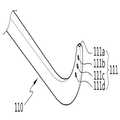
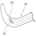
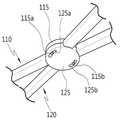
도 1은 본 발명의 일 실시예에 따른 수술 기구를 개략적으로 도시한 사시도이고, 도 2는 도 1에 나타낸 수술 기구의 분해 사시도이고, 도 3 및 도 4는 도 1에 나타낸 제 1 몸체부 및 제 2 몸체부의 측면도이고, 도 5는 도 1의 A부분을 이면에서 바라본 확대 사시도이고, 도 6은 도 1의 B부분을 확대 도시한 사시도이고, 도 7은 도 1의 B부분의 다른 실시 형태를 도시한 사시도이며, 도 8은 도 1의 C부분을 이면에서 바라본 확대 사시도이다.1 is a perspective view schematically showing a surgical instrument according to an embodiment of the present invention, Figure 2 is an exploded perspective view of the surgical instrument shown in Figure 1, Figures 3 and 4 are the first body portion shown in Figure 1 and 2 is a side view of the second body part, FIG. 5 is an enlarged perspective view of the portion A of FIG. 1 viewed from the back, FIG. 6 is an enlarged perspective view of the portion B of FIG. 1, and FIG. 7 is another embodiment of the portion B of FIG. 1. Figure 8 is a perspective view, Figure 8 is an enlarged perspective view of the C portion of FIG.
도 1 내지 도 8에 도시된 바와 같이, 본 발명의 일 실시예에 따른 수술 기구는 제 1 몸체부(110), 제 2 몸체부(120), 흡입부(200) 및 조명부(300) 등을 포함할 수 있다.As shown in Figure 1 to 8, the surgical instrument according to an embodiment of the present invention, the
본 발명의 수술 기구는 전체적으로 가위 형상을 갖는 조직 박리기로 구성될 수 있다.The surgical instrument of the present invention may be composed of a tissue exfoliator having a scissors shape as a whole.
제 1 몸체부(110)는 생체 조직 박리를 시행 시 출혈된 또는 출혈 중인 혈액 또는 이물질을 흡입하기 위해 선단에 흡입구(111)가 적어도 하나 형성된다. 예를 들어, 본 실시예에서 흡입구(111)는 제 1 몸체부(110)의 선단 전면에 1개(111a), 그리고 내측면에 2~3개(111b,111c,111d) 정도 형성되는 구성을 예시하였으나, 이에 한정되지 않고 다양한 개수와 형상을 가질 수 있다. 흡입구(111)는 후술할 흡입관 삽입홀(110a)과 연통되게 형성되며 후술할 흡입관(210)의 선단과 연결된다.At least one
제 1 몸체부(110)의 내부에는 후술할 흡입관(210)이 삽입되어 내장될 수 있도록 흡입관 삽입홀(110a)이 길이방향으로 길게 형성된다. 본 실시예에서는 흡입관 삽입홀(110a)이 제 1 몸체부(110)의 길이 방향으로 전체 형성되는 구성을 예시하였다. 그러나, 제 1 몸체부(110)의 선단으로부터 후술할 제 1 회전결합부(115)까지는 흡입관(210)이 삽입되어 완전히 내장되도록 제 1 몸체부(110)의 내부 중심을 관통하는 흡입관 삽입홀(110a)을 형성하고, 제 1 회전결합부(115)로부터 제 1 몸체부(110)의 후단까지는 흡입관(210)의 반경 부위가 끼워져 고정되도록 제 1 몸체부(110)의 일측면에 반구형의 홈 형태를 가지는 흡입관 고정홈(미도시)을 형성할 수도 있다. 또한, 흡입구(111)를 통해 흡입관 삽입홀(110a)로 흡입된 출혈 또는 이물질 등의 걸림을 방지하기 위하여 흡입관 삽입홀(110a)의 직경을 흡입구(111)의 직경보다 크게 형성하는 것이 바람직하다. 또한, 흡입관 삽입홀(110a)은 제 1 몸체부(110)의 전단에서 후방으로 갈수록 내경이 확대되도록 형성할 수도 있다.The suction
제 2 몸체부(120)는 제 1 몸체부(110)와 교차되어 후술할 회전결합부(115,125)에 의해 회전 가능하게 결합된다.The
제 2 몸체부(120)의 내부에는 후술할 광섬유(310)가 삽입되어 내장될 수 있도록 광섬유 삽입홀(120a)이 길이방향으로 길게 형성된다. 본 실시예에서는 광섬유 삽입홀(120a)이 제 2 몸체부(120)의 길이 방향으로 전체 형성되는 구성을 예시하였다. 그러나, 제 2 몸체부(120)의 후술할 조명구(121)로부터 후술할 제 2 회전결합 부(125)까지는 광섬유(310)가 삽입되어 완전히 내장되도록 제 2 몸체부(120)의 내부 중심을 관통하는 광섬유 삽입홀(120a)을 형성하고, 제 2 회전결합부(125)로부터 제 2 몸체부(120)의 후단까지는 광섬유(310)의 반경 부위가 끼워져 고정되도록 제 2 몸체부(120)의 일측면에 반구형의 홈 형태를 가지는 광섬유 고정홈(미도시)을 형성할 수도 있다.The optical
제 2 몸체부(120)에는 광섬유 삽입홀(120a)과 연통되게 형성되며 광섬유(310)의 선단이 노출되는 조명구(121)가 적어도 하나 형성된다. 여기서, 조명구(121)는 광섬유(310)가 제 1 몸체부(110)의 선단과 제 2 몸체부(120)의 선단의 벌어진 사이의 중앙 부위를 조명할 수 있도록 제 2 몸체부(120)의 선단으로부터 후방으로 일정거리 이격되어 내측면에 형성되는 것이 바람직하다.The
제 1 몸체부(110)와 제 2 몸체부(120)의 선단은 생체 조직 사이를 쉽게 벌릴 수 있도록 상향 또는 하향으로 벤딩되게 형성되는 것이 바람직하다. 또한, 제 1 몸체부(110)와 제 2 몸체부(120)의 후단에는 손가락을 각각 끼워 파지할 수 있도록 링 형태의 손잡이부(113,123)가 형성될 수 있다.The front end of the
제 1 몸체부(110)와 제 2 몸체부(120)는 회전결합부(115,125)에 의해 회전 가능하게 결합된다. 여기서, 회전결합부는 제 1 회전결합부(115)와 제 2 회전결합부(125)의 상호 회전 가능한 결합으로 구성된다.The
제 1 회전결합부(115)는 제 1 몸체부(110)의 대략 중앙 부위에 원형으로 일체로 형성되며, 일면의 가장자리부에 한 쌍의 결합돌기(115a,115b)가 형성된다.The first
제 2 회전결합부(125)는 제 2 몸체부(120)의 대략 중앙 부위에 원형으로 일 체로 형성되며, 제 1 회전결합부(115)의 일면과 대향되는 면의 가장자리부에 한 쌍의 결합돌기(115a,115b)가 끼워져 일정 회전 각도, 예컨대 대략 0~30도의 회전각 범위 내에서 회전하도록 결합되는 한 쌍의 결합홈(125a,125b)이 형성된다.The second
흡입부(200)는 생체 조직 박리 등과 같은 수술 중 환자의 출혈 부위에서 발생하는 혈액 또는 이물질 등을 흡입구(111)를 통해 흡입하기 위해 제 1 몸체부(110)에 구비된다.The
흡입부(200)는 선단이 흡입구(111)와 연결되도록 제 1 몸체부(110)에 삽입되어 내장되는 튜브관 형태의 흡입관(210)을 포함한다. 흡입관(210)은 제 1 몸체부(110) 내에 길이방향으로 길게 형성된 흡입관 삽입홀(110a)에 삽입되며, 선단이 흡입구(111)와 연결되고, 후단이 흡입관(210)에 흡입력을 제공하는 공지된 흡입장치(220)와 연결된다.The
조명부(300)는 제 1 몸체부(110)와 제 2 몸체부(120)의 선단 사이를 조명하기 위해 제 2 몸체부(120)에 구비된다.The
조명부(300)는 제 2 몸체부(120)에 삽입되어 내장되며, 광원에서 발생하는 광을 광 전송하여 제 1 몸체부(110)와 제 2 몸체부(120)의 선단 사이를 조사하도록 가이드 하는 광섬유(310)를 포함한다. 여기서, 광원(320)은 광섬유(310)에 광을 제공할 수 있는 다양한 형태의 광발생장치를 포함할 수 있고, 바람직하게는 발광다이오드(LED)일 수 있다. 광섬유(310)는 제 2 몸체부(120) 내에 형성된 광섬유 삽입홀(120a)에 삽입되며, 선단이 제 2 몸체부(120)의 조명구(121)에 노출되고, 후단이 광원(320)과 연결된다. 조명구(121)에 노출된 광섬유(310)는 제 1 몸체부(110)의 선단과 제 2 몸체부(120)의 선단이 벌어진 사이의 중앙 부위를 조명하도록 배치된다.The
본 실시예에서 조명부(300)는 광섬유(310)로 구성되는 것을 예시하였으나, 이에 한정되지 않고 도 7에 도시된 바와 같이, 조명부(300)는 제 1 몸체부(110)의 선단과 제 2 몸체부(120)의 선단이 벌어진 사이의 중앙 부위를 조명하도록 제 2 몸체부(120)의 선단으로부터 후방으로 일정거리 이격되어 내측면에 구비되는 전구 또는 LED 램프(311) 등으로 구성될 수 있다.In the present embodiment, the
이하, 도 9를 참조하여, 본 발명의 일 실시예에 따른 수술 기구의 작동을 구체적으로 설명한다.Hereinafter, with reference to Figure 9, the operation of the surgical instrument according to an embodiment of the present invention will be described in detail.
도 9는 본 발명에 따른 수술 기구의 사용 상태를 설명하기 위한 예시도이다.9 is an exemplary view for explaining a state of use of the surgical instrument according to the present invention.
도 9에 도시된 바와 같이, 수술자는 수술 기구의 손잡이부(113,123)에 손가락을 끼워 파지한 상태로 수술 기구를 신체 내부로 진입시키게 되는데, 수술 기구의 양 선단을 하향으로 한 상태로 생체 조직(1) 사이를 파고 들면서 조직 간격을 벌리는 조직 박리를 시행하면서 수술자가 원하는 수술 부위로 진입을 하게 된다. 이때, 조직 박리 등을 시행하는 과정에서 생체 조직(1) 사이에서 출혈이 발생하게 되는데, 본 발명에 따른 수술 기구의 제 1 몸체부(110)에 내장된 흡입관(210)을 이용하여 수술 중 환자의 출혈 부위에서 발생하는 혈액 및 이물질 등을 흡입구(111)를 통해 흡입하여 제거함으로써 수술 시야를 확보할 수 있게 된다.As shown in FIG. 9, the operator enters the surgical instrument into the body with the fingers held by the
또한, 수술자가 원하는 수술 부위로 진행을 위해 수술 기구를 더 깊이 진입시켜 조직 박리 수술 부위가 더 깊어지게 되면 어둡기 때문에 수술 시야를 확보하 기 어렵다. 이때, 본 발명에 따른 수술 기구의 제 2 몸체부(120)에 내장된 광섬유(310)를 이용하여 광원(320)에서 발생하는 광을 전송하여 제 1 몸체부(110)의 선단과 제 2 몸체부(120)의 선단이 벌어진 사이의 중앙 부위를 조명함으로써 수술 시야를 확보할 수 있게 된다.In addition, it is difficult for the operator to secure the surgical field of view because it is dark when the tissue detachment surgery site is deeper by entering the surgical instrument deeper to proceed to the desired surgical site. At this time, the front end and the second body of the
즉, 본 발명의 수술 기구는 수술 시 어둡고 출혈이 많은 조직을 박리할 때 수술 부위에서 발생하는 출혈을 흡입하고 조명을 비추어 조직 박리의 심도가 깊은 수술 부위의 시야를 확보할 수 있게 됨으로써, 수술자는 안전하고 신속한 수술을 할 수 있다.That is, the surgical instrument of the present invention can secure the field of view of the surgical site with a deep depth of tissue detachment by inhaling the bleeding generated in the surgical site and illuminating when the dark and bleeding tissue is peeled off during surgery. Safe and quick surgery
또한, 전체적으로 소형의 수술 기구에 조직 박리, 출혈 흡입 및 조명 기능과 같은 3가지 기능을 갖출 수 있도록 제작하여 사용상 편리성을 제공한다.In addition, it provides convenience in use by making it possible to have three functions, such as tissue detachment, bleeding suction and lighting function to the overall small surgical instruments.
이상 첨부된 도면을 참조하여 본 발명의 실시 예를 설명하였지만, 본 발명이 속하는 기술분야에서 통상의 지식을 가진 자는 본 발명이 그 기술적 사상이나 필수적인 특징을 변경하지 않고서 다른 구체적인 형태로 실시될 수 있다는 것을 이해할 수 있을 것이다. 그러므로 이상에서 기술한 실시 예들은 모든 면에서 예시적인 것이며 한정적이 아닌 것으로 이해해야만 한다. 본 발명의 범위는 상기 상세한 설명보다는 후술하는 특허청구범위에 의하여 나타내어지며, 특허청구범위의 의미 및 범위 그리고 그 균등 개념으로부터 도출되는 모든 변경 또는 변형된 형태가 본 발명의 범위에 포함되는 것으로 해석되어야 한다.Although embodiments of the present invention have been described above with reference to the accompanying drawings, those skilled in the art to which the present invention pertains may implement the present invention in other specific forms without changing the technical spirit or essential features thereof. I can understand that. It is therefore to be understood that the above-described embodiments are illustrative in all aspects and not restrictive. The scope of the present invention is shown by the following claims rather than the above description, and all changes or modifications derived from the meaning and scope of the claims and their equivalents should be construed as being included in the scope of the present invention. do.
도 1은 본 발명의 일 실시예에 따른 수술 기구를 개략적으로 도시한 사시도.1 is a perspective view schematically showing a surgical instrument according to an embodiment of the present invention.
도 2는 도 1에 나타낸 수술 기구의 분해 사시도.2 is an exploded perspective view of the surgical instrument shown in FIG.
도 3은 도 1에 나타낸 제 1 몸체부의 측면도.3 is a side view of the first body portion shown in FIG. 1;
도 4는 도 1에 나타낸 제 2 몸체부의 측면도.4 is a side view of the second body portion shown in FIG. 1;
도 5는 도 1의 A부분을 이면에서 바라본 확대 사시도.5 is an enlarged perspective view of the portion A of FIG. 1 viewed from the back;
도 6은 도 1의 B부분을 확대 도시한 사시도.6 is an enlarged perspective view of part B of FIG. 1;
도 7은 도 1의 B부분의 다른 실시 형태를 도시한 사시도.FIG. 7 is a perspective view showing another embodiment of part B of FIG. 1; FIG.
도 8은 도 1의 C부분을 이면에서 바라본 확대 사시도.8 is an enlarged perspective view of the portion C of FIG.
도 9는 본 발명에 따른 수술 기구의 사용 상태를 설명하기 위한 예시도.9 is an exemplary view for explaining a state of use of the surgical instrument according to the present invention.
< 도면의 주요 부분에 대한 부호의 설명 ><Description of Symbols for Main Parts of Drawings>
110 : 제 1 몸체부 111 : 흡입구110: first body portion 111: suction port
113 : 손잡이부 115 : 제 1 회전결합부113: handle portion 115: the first rotary coupling portion
120 : 제 2 몸체부 121 : 조명구120: second body portion 121: lighting fixture
123 : 손잡이부 125 : 제 2 회전결합부123: handle portion 125: second rotary coupling portion
200 : 흡입부 210 : 흡입관200: suction unit 210: suction tube
220 : 흡입장치 300 : 조명부220: suction device 300: lighting unit
310 : 광섬유 320 : 광원310: optical fiber 320: light source
Claims (17)
Translated fromKoreanPriority Applications (4)
| Application Number | Priority Date | Filing Date | Title |
|---|---|---|---|
| KR1020090036479AKR101096401B1 (en) | 2009-04-27 | 2009-04-27 | Surgical instruments |
| EP09010620AEP2246000B1 (en) | 2009-04-27 | 2009-08-18 | Surgical instrument |
| US12/583,726US20100274097A1 (en) | 2009-04-27 | 2009-08-24 | Surgical instrument |
| JP2009220895AJP5026485B2 (en) | 2009-04-27 | 2009-09-25 | Surgical instruments |
Applications Claiming Priority (1)
| Application Number | Priority Date | Filing Date | Title |
|---|---|---|---|
| KR1020090036479AKR101096401B1 (en) | 2009-04-27 | 2009-04-27 | Surgical instruments |
Publications (2)
| Publication Number | Publication Date |
|---|---|
| KR20100117819A KR20100117819A (en) | 2010-11-04 |
| KR101096401B1true KR101096401B1 (en) | 2011-12-21 |
Family
ID=42556675
Family Applications (1)
| Application Number | Title | Priority Date | Filing Date |
|---|---|---|---|
| KR1020090036479AExpired - Fee RelatedKR101096401B1 (en) | 2009-04-27 | 2009-04-27 | Surgical instruments |
Country Status (4)
| Country | Link |
|---|---|
| US (1) | US20100274097A1 (en) |
| EP (1) | EP2246000B1 (en) |
| JP (1) | JP5026485B2 (en) |
| KR (1) | KR101096401B1 (en) |
Families Citing this family (18)
| Publication number | Priority date | Publication date | Assignee | Title |
|---|---|---|---|---|
| KR101070049B1 (en)* | 2009-05-06 | 2011-10-04 | 국립암센터 | Surgical instrument |
| WO2014072976A1 (en)* | 2012-11-08 | 2014-05-15 | Emodi Omri | Intracavity illumination device |
| CN103126744A (en)* | 2013-01-23 | 2013-06-05 | 郭卫刚 | Tissue separating surgical instrument with optical fiber lighting and fluid guide functions |
| RU2705046C2 (en) | 2013-04-01 | 2019-11-01 | Винод В. ПАТХИ | Lighting device |
| USD938095S1 (en) | 2013-04-01 | 2021-12-07 | Pathy Medical, Llc | Lighting device |
| KR101567572B1 (en)* | 2014-04-28 | 2015-11-10 | 순천향대학교 산학협력단 | A forcep for pressurizing biological tissue |
| EP3145385A4 (en) | 2014-05-22 | 2018-02-14 | Invuity, Inc. | Medical device featuring cladded waveguide |
| CN104042261B (en)* | 2014-07-07 | 2016-10-05 | 王强 | Trachea automatic dilator |
| KR101513912B1 (en)* | 2014-09-25 | 2015-04-21 | 김철환 | The finger tissue exfoliation device for boob job |
| EP3031401B1 (en) | 2014-12-12 | 2017-07-05 | Marco Piciche' | Illuminating medical instrument |
| CN106562807A (en)* | 2016-08-29 | 2017-04-19 | 闫东明 | Neurosurgical device for strutting and drainage of rear skull |
| CN106333729A (en)* | 2016-09-23 | 2017-01-18 | 吕清林 | Clinical vessel clamp for internal-medicine department |
| WO2018092285A1 (en)* | 2016-11-18 | 2018-05-24 | 信行 櫻澤 | Suction forceps for endoscopic surgery |
| CN108403163B (en)* | 2018-02-22 | 2020-04-24 | 曹元江 | Novel neurosurgery back skull distraction drainage device |
| CN108852264A (en)* | 2018-06-25 | 2018-11-23 | 东莞市联洲知识产权运营管理有限公司 | Electric T-shaped mouth gag for operation |
| CN108852265A (en)* | 2018-06-25 | 2018-11-23 | 东莞市联洲知识产权运营管理有限公司 | Detachable electric T-shaped mouth gag for operation |
| CN109009276B (en)* | 2018-08-25 | 2023-05-16 | 张颖 | A retractor for cardiothoracic surgery |
| KR20200142227A (en)* | 2019-06-12 | 2020-12-22 | 가톨릭대학교 산학협력단 | Apparatus for ophthalmic surgery capable of self-lighting |
Citations (3)
| Publication number | Priority date | Publication date | Assignee | Title |
|---|---|---|---|---|
| KR200325199Y1 (en)* | 2003-06-10 | 2003-09-03 | 주식회사 탑알앤디 | Optical suction catheter |
| US20080119694A1 (en) | 2006-11-17 | 2008-05-22 | Lee James K | Catheter with omni-Directional optical tip having isolated optical paths |
| JP2009056289A (en) | 2007-06-29 | 2009-03-19 | Biosense Webster Inc | Ablation catheter with optically transparent electricity conductive tip |
Family Cites Families (14)
| Publication number | Priority date | Publication date | Assignee | Title |
|---|---|---|---|---|
| US390561A (en)* | 1888-10-02 | Dental mouth-opening forceps | ||
| US2333740A (en)* | 1943-05-11 | 1943-11-09 | Edward L Rasmussen | Removable blade shears |
| US3980086A (en) | 1974-02-28 | 1976-09-14 | Bio-Medicus, Inc. | Fluid conveying surgical instrument |
| US5147356A (en)* | 1991-04-16 | 1992-09-15 | Microsurge, Inc. | Surgical instrument |
| US6185356B1 (en) | 1995-06-27 | 2001-02-06 | Lumitex, Inc. | Protective cover for a lighting device |
| US20020058931A1 (en)* | 1995-06-27 | 2002-05-16 | Jeffrey R. Parker | Light delivery system and applications thereof |
| US5727569A (en)* | 1996-02-20 | 1998-03-17 | Cardiothoracic Systems, Inc. | Surgical devices for imposing a negative pressure to fix the position of cardiac tissue during surgery |
| US5891017A (en)* | 1997-01-31 | 1999-04-06 | Baxter Research Medical, Inc. | Surgical stabilizer and method for isolating and immobilizing cardiac tissue |
| US20050171408A1 (en)* | 1997-07-02 | 2005-08-04 | Parker Jeffery R. | Light delivery systems and applications thereof |
| JPH11226026A (en)* | 1998-02-18 | 1999-08-24 | Olympus Optical Co Ltd | Surgical surgical tools |
| EP1208331A4 (en)* | 1999-07-20 | 2005-01-05 | Mickey M Karram | Surgical illumination device and method of use |
| US20050272977A1 (en)* | 2004-04-14 | 2005-12-08 | Usgi Medical Inc. | Methods and apparatus for performing endoluminal procedures |
| US8517933B2 (en)* | 2006-06-13 | 2013-08-27 | Intuitive Surgical Operations, Inc. | Retraction of tissue for single port entry, robotically assisted medical procedures |
| KR101070049B1 (en)* | 2009-05-06 | 2011-10-04 | 국립암센터 | Surgical instrument |
- 2009
- 2009-04-27KRKR1020090036479Apatent/KR101096401B1/ennot_activeExpired - Fee Related
- 2009-08-18EPEP09010620Apatent/EP2246000B1/ennot_activeNot-in-force
- 2009-08-24USUS12/583,726patent/US20100274097A1/ennot_activeAbandoned
- 2009-09-25JPJP2009220895Apatent/JP5026485B2/ennot_activeExpired - Fee Related
Patent Citations (3)
| Publication number | Priority date | Publication date | Assignee | Title |
|---|---|---|---|---|
| KR200325199Y1 (en)* | 2003-06-10 | 2003-09-03 | 주식회사 탑알앤디 | Optical suction catheter |
| US20080119694A1 (en) | 2006-11-17 | 2008-05-22 | Lee James K | Catheter with omni-Directional optical tip having isolated optical paths |
| JP2009056289A (en) | 2007-06-29 | 2009-03-19 | Biosense Webster Inc | Ablation catheter with optically transparent electricity conductive tip |
Also Published As
| Publication number | Publication date |
|---|---|
| JP2010253237A (en) | 2010-11-11 |
| JP5026485B2 (en) | 2012-09-12 |
| KR20100117819A (en) | 2010-11-04 |
| EP2246000B1 (en) | 2012-06-06 |
| EP2246000A1 (en) | 2010-11-03 |
| US20100274097A1 (en) | 2010-10-28 |
Similar Documents
| Publication | Publication Date | Title |
|---|---|---|
| KR101096401B1 (en) | Surgical instruments | |
| KR101070049B1 (en) | Surgical instrument | |
| EP1278007B1 (en) | Light delivery systems and applications thereof | |
| CN102164621B (en) | Cycloolefin polymers and copolymers for medical devices | |
| EP0993579B1 (en) | Light delivery system and applications thereof | |
| EP1561137B1 (en) | Illuminated surgical retractor | |
| JP6934889B2 (en) | Nasal flap implant and its transplant method | |
| JP2018524078A (en) | Device and kit for open surgery support | |
| CN104274229A (en) | Light guide puncture needle combination | |
| GB2505463A (en) | Transparent retractor with light | |
| US9072541B2 (en) | Surgical scalpel handle with illuminator | |
| US20020038121A1 (en) | Apparatus system and for identifying a treatment tool within a patient's body | |
| CN116059512A (en) | Disposal Instruments for Endoscopes | |
| CN222068341U (en) | Auxiliary illumination early warning optical fiber for human body internal operation | |
| US20100280328A1 (en) | Methods and systems for illumination during phlebectomy procedures | |
| CN102889537B (en) | Lateral light-emitting device capable of being jointed with medullary cavity guide needle | |
| KR101796773B1 (en) | Lighting unit for laparoscopic surgery and laparoscopic surgery system having thereof | |
| CN208319307U (en) | A kind of tungsten needle protection electric knife with attraction illumination functions | |
| CN221636092U (en) | A searchlighting device that is arranged in laparoscopic surgery mesenteric vessel to develop | |
| US12433667B2 (en) | Smoke evacuation electrosurgical pencil with lighting | |
| CN206381198U (en) | Armpit lymphadenectomy special drag hook | |
| JP7209976B2 (en) | Irradiation equipment for endoscopic surgery | |
| EP4559415A1 (en) | Transparent scalpel handle and bayonet with universal blade holder with and without optical lenses | |
| CN202096582U (en) | Intraoperative deep illuminating and attracting system | |
| JP2020130666A (en) | Medical suction apparatus |
Legal Events
| Date | Code | Title | Description |
|---|---|---|---|
| A201 | Request for examination | ||
| PA0109 | Patent application | St.27 status event code:A-0-1-A10-A12-nap-PA0109 | |
| PA0201 | Request for examination | St.27 status event code:A-1-2-D10-D11-exm-PA0201 | |
| R18-X000 | Changes to party contact information recorded | St.27 status event code:A-3-3-R10-R18-oth-X000 | |
| D13-X000 | Search requested | St.27 status event code:A-1-2-D10-D13-srh-X000 | |
| D14-X000 | Search report completed | St.27 status event code:A-1-2-D10-D14-srh-X000 | |
| PG1501 | Laying open of application | St.27 status event code:A-1-1-Q10-Q12-nap-PG1501 | |
| E902 | Notification of reason for refusal | ||
| PE0902 | Notice of grounds for rejection | St.27 status event code:A-1-2-D10-D21-exm-PE0902 | |
| P11-X000 | Amendment of application requested | St.27 status event code:A-2-2-P10-P11-nap-X000 | |
| P13-X000 | Application amended | St.27 status event code:A-2-2-P10-P13-nap-X000 | |
| E701 | Decision to grant or registration of patent right | ||
| PE0701 | Decision of registration | St.27 status event code:A-1-2-D10-D22-exm-PE0701 | |
| GRNT | Written decision to grant | ||
| PR0701 | Registration of establishment | St.27 status event code:A-2-4-F10-F11-exm-PR0701 | |
| PR1002 | Payment of registration fee | St.27 status event code:A-2-2-U10-U11-oth-PR1002 Fee payment year number:1 | |
| PG1601 | Publication of registration | St.27 status event code:A-4-4-Q10-Q13-nap-PG1601 | |
| PR1001 | Payment of annual fee | St.27 status event code:A-4-4-U10-U11-oth-PR1001 Fee payment year number:4 | |
| FPAY | Annual fee payment | Payment date:20151214 Year of fee payment:5 | |
| PR1001 | Payment of annual fee | St.27 status event code:A-4-4-U10-U11-oth-PR1001 Fee payment year number:5 | |
| FPAY | Annual fee payment | Payment date:20161209 Year of fee payment:6 | |
| PR1001 | Payment of annual fee | St.27 status event code:A-4-4-U10-U11-oth-PR1001 Fee payment year number:6 | |
| FPAY | Annual fee payment | Payment date:20171212 Year of fee payment:7 | |
| PR1001 | Payment of annual fee | St.27 status event code:A-4-4-U10-U11-oth-PR1001 Fee payment year number:7 | |
| LAPS | Lapse due to unpaid annual fee | ||
| PC1903 | Unpaid annual fee | St.27 status event code:A-4-4-U10-U13-oth-PC1903 Not in force date:20181214 Payment event data comment text:Termination Category : DEFAULT_OF_REGISTRATION_FEE | |
| PC1903 | Unpaid annual fee | St.27 status event code:N-4-6-H10-H13-oth-PC1903 Ip right cessation event data comment text:Termination Category : DEFAULT_OF_REGISTRATION_FEE Not in force date:20181214 |