KR101096297B1 - Cyst suction device - Google Patents
Cyst suction deviceDownload PDFInfo
- Publication number
- KR101096297B1 KR101096297B1KR1020100025268AKR20100025268AKR101096297B1KR 101096297 B1KR101096297 B1KR 101096297B1KR 1020100025268 AKR1020100025268 AKR 1020100025268AKR 20100025268 AKR20100025268 AKR 20100025268AKR 101096297 B1KR101096297 B1KR 101096297B1
- Authority
- KR
- South Korea
- Prior art keywords
- suction
- cyst
- barrel
- needle
- tube
- Prior art date
- Legal status (The legal status is an assumption and is not a legal conclusion. Google has not performed a legal analysis and makes no representation as to the accuracy of the status listed.)
- Expired - Fee Related
Links
Images


Classifications
- A—HUMAN NECESSITIES
- A61—MEDICAL OR VETERINARY SCIENCE; HYGIENE
- A61B—DIAGNOSIS; SURGERY; IDENTIFICATION
- A61B17/00—Surgical instruments, devices or methods
- A61B17/22—Implements for squeezing-off ulcers or the like on inner organs of the body; Implements for scraping-out cavities of body organs, e.g. bones; for invasive removal or destruction of calculus using mechanical vibrations; for removing obstructions in blood vessels, not otherwise provided for
- A—HUMAN NECESSITIES
- A61—MEDICAL OR VETERINARY SCIENCE; HYGIENE
- A61B—DIAGNOSIS; SURGERY; IDENTIFICATION
- A61B17/00—Surgical instruments, devices or methods
- A61B17/00234—Surgical instruments, devices or methods for minimally invasive surgery
- A—HUMAN NECESSITIES
- A61—MEDICAL OR VETERINARY SCIENCE; HYGIENE
- A61B—DIAGNOSIS; SURGERY; IDENTIFICATION
- A61B17/00—Surgical instruments, devices or methods
- A61B17/22—Implements for squeezing-off ulcers or the like on inner organs of the body; Implements for scraping-out cavities of body organs, e.g. bones; for invasive removal or destruction of calculus using mechanical vibrations; for removing obstructions in blood vessels, not otherwise provided for
- A61B2017/22079—Implements for squeezing-off ulcers or the like on inner organs of the body; Implements for scraping-out cavities of body organs, e.g. bones; for invasive removal or destruction of calculus using mechanical vibrations; for removing obstructions in blood vessels, not otherwise provided for with suction of debris
Landscapes
- Health & Medical Sciences (AREA)
- Surgery (AREA)
- Life Sciences & Earth Sciences (AREA)
- Heart & Thoracic Surgery (AREA)
- Nuclear Medicine, Radiotherapy & Molecular Imaging (AREA)
- Engineering & Computer Science (AREA)
- Biomedical Technology (AREA)
- Medical Informatics (AREA)
- Molecular Biology (AREA)
- Animal Behavior & Ethology (AREA)
- General Health & Medical Sciences (AREA)
- Public Health (AREA)
- Veterinary Medicine (AREA)
- Vascular Medicine (AREA)
- Orthopedic Medicine & Surgery (AREA)
- External Artificial Organs (AREA)
Abstract
Translated fromKoreanDescription
Translated fromKorean본 발명은 수술 장치에 관한 것으로, 더욱 상세하게는 미니개복술, 싱글포트(single-port)를 포함한 복강경 수술 또는 무흉터 수술(Natural Orifice Transluminal Endoscopic Surgery; NOTES) 시 낭포 내 액체를 안전하게 제거하기 위한 낭종 흡입 장치에 관한 것이다.The present invention relates to a surgical device, and more particularly, to a cyst for safely removing the fluid in the cyst during laparoscopic surgery or a minimal scar surgery (Natural Orifice Transluminal Endoscopic Surgery (NoteS)) A suction device.
일반적으로 환자 치료를 위한 기존의 개복 절개 수술의 경우, 절개 부위가 크고 수술 시 발생하는 출혈량이 커서 수술 이후의 환자 회복이 더디고, 수술 후 커다란 흉터가 남게 되어 환자의 이후 생활에도 지장을 주게 된다. 이와 같은 개복 절개 수술의 단점을 극복하기 위해 최근 최소 침습 수술(Minimal Invasive Surgery; MIS) 및 무흉터 수술(Natural Orifice Transluminal Endoscopic Surgery; NOTES) 등의 새로운 수술 기법들이 개발되고 있다.In general, the conventional open incision surgery for the treatment of patients, the incision area is large and the amount of bleeding during surgery is large, the patient recovery after surgery is slow, large scars remain after the operation will interfere with the patient's future life. Recently, new surgical techniques such as Minimal Invasive Surgery (MIS) and Natural Orifice Transluminal Endoscopic Surgery (NOTES) have been developed to overcome the shortcomings of such open incision surgery.
최소 침습 수술은 수술을 위해 필요한 절개 부위를 최소화하기 위해 특별히 고안된 가늘고 긴 수술 도구를 써서 환자의 신체에 최소한의 부위만을 절개하여 시술하는 수술 기법이며, 무흉터 수술은 환자의 체내에 있는 시술 부위로 수술 도구를 이송하기 위해 환자의 신체를 절개하지 않고, 사람의 신체에 자연적으로 존재하는 구멍(식도, 항문, 질, 요도 등)을 통해 수술 도구를 삽입하여 체내 시술 부위로 수술 도구를 이송, 시술하는 수술 기법이다. 이러한 최소 침습 수술 및 무흉터 수술은 시술을 위해 필요한 절개 부위가 적고 시술 시 출혈량이 개복 수술에 비해 현저히 적으므로, 수술 후 환자의 회복 기간이 빠르고 외부로 드러나는 흉터가 작다는 장점이 있어, 최근 그 시술 건수가 현저히 증가하고 있다.Minimally Invasive Surgery is a surgical technique that involves cutting only the smallest part of the patient's body using an elongated surgical tool specially designed to minimize the incision needed for surgery. Instead of dissecting the patient's body to transport the surgical tool, the surgical tool is inserted through the hole (esophagus, anus, vagina, urethra, etc.) that is naturally present in the human body, and the surgical tool is transferred to the internal surgical site. It is a surgical technique. Since minimal minimally invasive surgery and scarless surgery require fewer incisions and significantly less bleeding compared to laparotomy, the patient's recovery period is fast after surgery and the scars that appear externally are small. The number of procedures is increasing significantly.
미니개복술, 싱글포트(single-port)를 포함한 복강경 수술 또는 무흉터 수술을 통해 환자 몸 안의 낭포 내 액체를 제거하고자 할 때, 기존에는 바늘로 낭포를 터뜨린 후 복강경용 흡입장치를 이용하여 낭포 내 액체를 흡입하는 방식을 취하였으나, 이 경우 낭포를 터뜨렸을 때 낭포 내 액체가 외부로 흘러내리는 문제가 있었다.When you want to remove the cyst fluid in the patient's body through mini-laparotomy, laparoscopic surgery including single-port, or scarless surgery, the cyst liquid with a laparoscopic inhalation device has been used. Inhalation was taken, but in this case there was a problem that the liquid in the cyst flows out when the cyst has burst.
따라서, 종양 제거 수술 시 이러한 낭포 내 액체에 종양 세포가 포함되어 있을 가능성이 있으므로, 보다 안전한 종양 제거 시술을 위해서는 낭포 내부의 액체를 외부로 흘러내리지 않게 하면서 흡입해낼 수 있는 수술 장치가 필요하다.Therefore, since tumor cells may be contained in the liquid in the cyst during tumor removal surgery, a surgical device capable of inhaling the liquid inside the cyst without flowing out is required for a safer tumor removal procedure.
본 발명은 상기와 같은 문제점을 해결하기 위하여 안출된 것으로서, 미니개복술, 싱글포트(single-port) 수술을 포함한 복강경 수술 또는 무흉터 수술 시 낭포 내 액체를 안전하게 흡입하여 제거할 수 있는 낭종 흡입 장치를 제공하는데 그 목적이 있다.The present invention has been made to solve the above problems, a cyst inhalation device that can safely inhale and remove the fluid in the cysts during laparoscopic surgery or scarless surgery, including mini-laparotomy, single-port surgery The purpose is to provide.
본 발명의 목적들은 이상에서 언급한 목적들로 제한되지 않으며, 언급되지 않은 또 다른 목적들은 아래의 기재로부터 당업자에게 명확하게 이해되어질 수 있을 것이다.The objects of the present invention are not limited to the above-mentioned objects, and other objects not mentioned can be clearly understood by those skilled in the art from the following description.
상기 목적을 달성하기 위한 본 발명의 바람직한 실시예에 따른 낭종 흡입 장치는, 낭포를 흡착 고정 및 파지하기 위한 제 1 흡입구가 형성된 경통부와, 상기 경통부의 내부에 전후방향으로 이동 가능하게 삽입되며 상기 낭포를 찔러 상기 낭포 내부의 액체를 흡입하기 위한 제 2 흡입구가 형성된 바늘부와, 상기 경통부가 상기 낭포를 흡착 고정 및 파지하도록 상기 제 1 흡입구에 흡입력을 제공하는 제 1 흡입부와, 상기 경통부에 의한 상기 낭포의 흡착 고정 및 파지 상태에서 상기 바늘부가 상기 낭포 내부의 액체를 흡입하도록 상기 제 2 흡입구에 흡입력을 제공하는 제 2 흡입부를 포함할 수 있다.The cyst suction device according to a preferred embodiment of the present invention for achieving the above object is a cylindrical portion formed with a first suction port for adsorption fixing and gripping of the cyst, and inserted into the inner side of the barrel to be movable in a forward and backward direction. A needle portion having a second suction port for sucking liquid inside the cyst, a first suction portion providing suction force to the first suction port so as to suck and fix and hold the cysts; A second suction unit may provide a suction force to the second suction port to suck the liquid in the cyst inside the suction and fixation state of the cyst.
상기 경통부는, 상기 제 1 흡입구가 내부를 관통하도록 형성되는 흡입경통과, 상기 흡입경통의 후단부와 결합되며 상기 바늘부가 삽입되어 상기 흡입경통까지 도달하도록 가이드하는 가이드경통으로 구성될 수 있다.The barrel may include a suction barrel formed to penetrate the inside of the first suction port, and a guide barrel coupled to a rear end of the suction barrel and guided to reach the suction barrel by inserting the needle part.
또한, 상기 흡입경통의 내부에는 상기 바늘부의 이동경로를 가이드하는 바늘가이드관이 마련될 수 있다.In addition, the inside of the suction barrel may be provided with a needle guide tube for guiding the movement path of the needle portion.
또한, 상기 바늘가이드관의 선단은 상기 흡입경통의 선단보다 안쪽에 위치하도록 형성되며, 상기 바늘가이드관의 후단은 상기 가이드경통과 연결되는 부위를 밀폐하도록 형성되는 것이 바람직하다.In addition, the front end of the needle guide tube is formed to be located inward from the front end of the suction tube, the rear end of the needle guide tube is preferably formed to seal the portion connected to the guide tube.
또한, 상기 경통부는 상기 바늘부의 삽입 방향에 대하여 직선 형태의 경로를 가질 수도 있고, 싱글포트 시술 시 인접한 수술기구 간 간섭 현상을 최소화하기 위해 상기 바늘부의 삽입 방향에 대하여 굴곡된 형태의 경로를 가질 수도 있다. 상기 경통부가 상기 바늘부의 삽입 방향에 대하여 굴곡된 형태의 경로를 가지도록 설계할 경우, 상기 바늘부는 상기 경통부의 굴곡 형상에 따라 변형 가능하도록 탄성을 가지는 것이 바람직하다.In addition, the barrel may have a straight path with respect to the insertion direction of the needle, or may have a curved path with respect to the insertion direction of the needle in order to minimize interference between adjacent surgical instruments during a single port procedure. have. When the barrel portion is designed to have a curved path with respect to the insertion direction of the needle portion, the needle portion preferably has elasticity to be deformable according to the bending shape of the barrel portion.
상기 제 1 흡입부는, 상기 흡입경통과 연결되어 상기 제 1 흡입구에 흡입력을 제공하는 제 1 흡입튜브와, 상기 제 1 흡입튜브 상에 마련되며 상기 제 1 흡입구에 제공되는 흡입력을 조절하는 제 1 흡입조절밸브로 구성될 수 있다.The first suction part may include a first suction tube connected to the suction tube to provide suction power to the first suction port, and a first suction provided on the first suction tube to adjust suction force provided to the first suction port. It can be composed of a control valve.
상기 제 2 흡입부는, 상기 바늘부와 연결되어 상기 제 2 흡입구에 흡입력을 제공하는 제 2 흡입튜브와, 상기 바늘부와 상기 제 2 흡입튜브의 연결부위에 마련되며 상기 제 2 흡입구에 제공되는 흡입력을 조절하는 제 2 흡입조절밸브로 구성될 수 있다.The second suction part is provided with a second suction tube connected to the needle part to provide suction power to the second suction port, and a suction force provided at a connection portion between the needle part and the second suction tube and provided to the second suction port. It may be configured as a second suction control valve to control.
여기서, 상기 제 2 흡입조절밸브의 선단부에는 상기 바늘부가 결합되고, 상기 제 2 흡입조절밸브의 후단부에는 상기 제 2 흡입튜브가 연결된다.Here, the needle portion is coupled to the front end of the second suction control valve, and the second suction tube is connected to the rear end of the second suction control valve.
또한, 상기 제 1 흡입튜브와 상기 제 2 흡입튜브는 커넥터부에 의해 한 개 또는 두 개의 외부 흡입장치와 연결될 수 있다.In addition, the first suction tube and the second suction tube may be connected to one or two external suction devices by a connector part.
또한, 상기 제 1 흡입조절밸브 및 상기 제 2 흡입조절밸브는 밸브케이스에 수납되며, 상기 가이드경통은 상기 밸브케이스에 착탈 가능하게 결합될 수 있다.In addition, the first suction control valve and the second suction control valve is accommodated in the valve case, the guide barrel may be detachably coupled to the valve case.
또한, 상기 밸브케이스는, 상기 제 1 흡입조절밸브가 고정 장착되는 제 1 밸브고정장착부와, 상기 제 2 흡입조절밸브가 전후방향으로 슬라이드 이동 가능하게 장착되는 제 2 밸브이동장착부로 구성될 수 있다.The valve case may include a first valve fixing mounting part in which the first suction control valve is fixedly mounted, and a second valve moving mounting part in which the second suction control valve is slidably movable in the front-rear direction. .
또한, 상기 제 2 흡입조절밸브의 선단에 결합된 바늘부의 전후 이동을 조절할 수 있도록 상기 제 2 흡입조절밸브에 바늘이동조절부가 마련되는 것이 바람직하다.In addition, it is preferable that a needle movement control part is provided in the second suction control valve so as to adjust the forward and backward movement of the needle part coupled to the tip of the second suction control valve.
또한, 상기 바늘이동조절부는 상기 바늘부를 이동시킨 후 위치를 고정할 수 있도록 상기 제 2 흡입조절밸브를 상기 밸브케이스에 록킹하는 구조를 가진다.In addition, the needle movement control unit has a structure for locking the second suction control valve to the valve case to fix the position after moving the needle.
또한, 본 발명의 낭종 흡입 장치는, 경통부와, 상기 경통부의 내부에 전후방향으로 이동 가능하게 삽입되는 바늘부와, 상기 경통부가 상기 낭포를 흡착 고정 및 파지하도록 상기 경통부에 1차적으로 흡입력을 제공하고 상기 경통부에 의한 상기 낭포의 흡착 고정 및 파지 상태에서 상기 바늘부가 상기 낭포 내부의 액체를 흡입하도록 상기 바늘부에 2차적으로 흡입력을 제공하는 흡입부를 포함할 수 있다.In addition, the cyst inhalation apparatus of the present invention provides a suction force primarily in the barrel portion, a needle portion inserted into the barrel portion so as to be movable in the front-rear direction, and the barrel portion so as to suck and fix and hold the cyst. And a suction part providing secondary suction force to the needle part so as to suck the liquid inside the cyst in the suction and fixation state of the cyst by the barrel part.
또한, 본 발명의 낭종 흡입 장치는, 낭포를 흡착 고정 및 파지하기 위한 제 1 흡입구가 형성된 경통부와, 상기 경통부의 내부에 전후방향으로 이동 가능하게 삽입되며 상기 낭포를 찔러 상기 낭포 내부의 액체를 흡입하기 위한 제 2 흡입구가 형성된 바늘부와, 상기 경통부와 연결되어 상기 제 1 흡입구에 흡입력을 제공하는 제 1 흡입튜브와, 상기 바늘부와 연결되어 상기 제 2 흡입구에 흡입력을 제공하는 제 2 흡입튜브와, 상기 제 1 흡입튜브 상에 마련되며 상기 제 1 흡입구에 제공되는 흡입력을 조절하는 제 1 흡입조절밸브와, 상기 바늘부와 상기 제 2 흡입튜브의 연결부위에 마련되며 상기 제 2 흡입구에 제공되는 흡입력을 조절하는 제 2 흡입조절밸브를 포함할 수 있다.In addition, the cyst suction device of the present invention is inserted into the barrel portion formed with a first suction port for adsorbing, fixing and gripping the cyst, and movable in the front and rear direction inside the barrel portion, and stabs the cyst to suck the liquid inside the cyst. A needle part having a second suction port for forming a first suction tube connected to the barrel and providing a suction force to the first suction port, and a second suction tube connected to the needle part to provide suction force to the second suction port And a first suction control valve provided on the first suction tube and adjusting the suction force provided to the first suction port, and provided at a connection portion between the needle part and the second suction tube and provided to the second suction port. It may include a second suction control valve for adjusting the suction force.
기타 실시예들의 구체적인 사항들은 상세한 설명 및 도면들에 포함되어 있다.Specific details of other embodiments are included in the detailed description and the drawings.
상기한 바와 같은 본 발명의 낭종 흡입 장치에 따르면, 미니개복술, 싱글포트(single-port) 수술을 포함한 복강경 수술 또는 무흉터 수술 시 낭포 내 액체를 안전하게 흡입하여 제거할 수 있도록 구조를 개선함으로써, 환자의 안전성을 높이고 보다 안전한 종양 제거 시술이 가능하다.According to the cyst inhalation device of the present invention as described above, by improving the structure to safely inhale and remove the fluid in the cysts during laparoscopic surgery or scarless surgery including mini-laparotomy, single-port surgery, It is possible to increase the safety and safer tumor removal procedure.
또한, 본 발명은 2중 흡입구조로 설계되어 낭포를 팁에 고정시킨 상태에서 낭포의 파지가 가능하며, 낭포 내 액체 흡입으로 인해 낭포의 변형이 일어나더라도 낭포가 팁에 계속 부착되어 있으므로 낭포 내 액체가 외부로 흘러내리는 것을 방지할 수 있다.In addition, the present invention is designed as a double suction structure is possible to grasp the cysts in the state that is fixed to the tip, even if the cyst deforms due to the inhalation of the liquid in the cysts because the cysts are still attached to the tip liquid in the cysts Can be prevented from flowing to the outside.
또한, 본 발명은 상황에 따라 한 개 혹은 두 개의 외부 흡입장치를 연결하여 바늘부의 내, 외부의 흡입력을 독립적으로 조절할 수 있다.In addition, according to the present invention, one or two external suction devices may be connected to each other to independently adjust suction force inside and outside the needle part.
또한, 본 발명은 팁 부위를 옆으로 휘도록 설계하여 single-port 시술 시 다른 수술도구로 인한 간섭을 최소화할 수 있다.In addition, the present invention is designed to bend the tip portion sideways to minimize the interference caused by other surgical instruments during single-port procedures.
본 발명의 효과들은 이상에서 언급한 효과들로 제한되지 않으며, 언급되지 않은 또 다른 효과들은 청구범위의 기재로부터 당업자에게 명확하게 이해될 수 있을 것이다.The effects of the present invention are not limited to the above-mentioned effects, and other effects not mentioned will be clearly understood by those skilled in the art from the description of the claims.
도 1은 본 발명의 바람직한 실시예에 따른 낭종 흡입 장치의 결합 사시도,
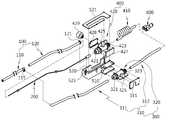
도 2는 도 1의 분해 사시도,
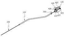
도 3은 도 1의 A부분에 대한 조립 상태를 도시한 도면,
도 4는 바늘부를 흡입경통에 삽입하는 상태를 도시한 도면,
도 5는 흡입경통의 단면도,
도 6은 바늘부를 가이드경통에 삽입하는 상태를 도시한 도면,
도 7은 가이드경통과 바늘부의 조립 상태를 도시한 도면,
도 8은 바늘부와 제 2 흡입조절밸브의 조립 상태를 도시한 도면,
도 9는 제 2 흡입조절밸브와 슬라이딩가이드부재의 조립 상태를 도시한 도면,
도 10은 밸브케이스와 제 2 흡입조절밸브의 조립 상태를 도시한 도면,
도 11은 밸브케이스와 흡입조절밸브의 결합 상태를 도시한 도면,
도 12는 흡입조절밸브와 흡입튜브의 조립 상태를 도시한 도면,
도 13은 흡입조절밸브와 흡입튜브의 결합 상태를 도시한 도면,
도 14는 도 12에서 커넥터부의 다른 실시예를 도시한 도면,
도 15 및 16은 본 발명의 낭종 흡입 장치의 제 1 작동 상태를 도시한 예시도, 그리고,
도 17 및 18은 본 발명의 낭종 흡입 장치의 제 2 작동 상태를 도시한 예시도이다.1 is a combined perspective view of a cyst suction device according to a preferred embodiment of the present invention,
2 is an exploded perspective view of FIG. 1;
3 is a view illustrating an assembled state of part A of FIG. 1;
4 is a view showing a state in which the needle portion is inserted into the suction barrel,
5 is a cross-sectional view of the suction barrel,
6 is a view showing a state in which the needle portion is inserted into the guide barrel,
7 is a view showing an assembled state of the guide barrel and the needle portion,
8 is a view showing the assembled state of the needle portion and the second suction control valve,
9 is a view illustrating an assembled state of the second suction control valve and the sliding guide member;
10 is a view showing an assembled state of the valve case and the second suction control valve,
11 is a view showing a combined state of the valve case and the suction control valve,
12 is a view showing the assembly state of the suction control valve and the suction tube,
13 is a view showing a coupling state of the suction control valve and the suction tube,
14 is a view showing another embodiment of the connector unit in FIG. 12;
15 and 16 are exemplary views showing a first operating state of the cyst inhalation device of the present invention, and
17 and 18 are exemplary views showing a second operating state of the cyst inhalation device of the present invention.
본 발명의 이점 및 특징, 그리고 그것들을 달성하는 방법은 첨부되는 도면과 함께 상세하게 후술되어 있는 실시예들을 참조하면 명확해질 것이다. 그러나 본 발명은 이하에서 개시되는 실시 예들에 한정되는 것이 아니라 서로 다른 다양한 형태로 구현될 수 있으며, 단지 본 실시예는 본 발명의 개시가 완전하도록 하고, 본 발명이 속하는 기술분야에서 통상의 지식을 가진 자에게 발명의 범주를 완전하게 알려주기 위해 제공되는 것이며, 본 발명은 청구항의 범주에 의해 정의될 뿐이다. 명세서 전체에 걸쳐 동일 참조 부호는 동일 구성요소를 지칭한다.Advantages and features of the present invention and methods for achieving them will be apparent with reference to the embodiments described below in detail with the accompanying drawings. However, the present invention is not limited to the embodiments disclosed below, but can be implemented in various different forms, only the embodiments are to make the disclosure of the present invention complete, and the general knowledge in the art to which the present invention belongs It is provided to fully convey the scope of the invention to those skilled in the art, and the present invention is defined only by the scope of the claims. Like reference numerals refer to like elements throughout.
이하, 첨부된 도면들을 참조하여 본 발명의 바람직한 실시예에 따른 낭종 흡입 장치를 상세히 설명하기로 한다. 참고로 본 발명을 설명함에 있어서 관련된 공지 기능 혹은 구성에 대한 구체적인 설명이 본 발명의 요지를 불필요하게 흐릴 수 있다고 판단되는 경우 그 상세한 설명을 생략한다.Hereinafter, a cyst suction device according to a preferred embodiment of the present invention will be described in detail with reference to the accompanying drawings. In the following description, well-known functions or constructions are not described in detail to avoid unnecessarily obscuring the subject matter of the present invention.
도 1은 본 발명의 바람직한 실시예에 따른 낭종 흡입 장치의 결합 사시도, 도 2는 도 1의 분해 사시도, 도 3은 도 1의 A부분에 대한 조립 상태를 도시한 도면, 도 4는 바늘부를 흡입경통에 삽입하는 상태를 도시한 도면, 도 5는 흡입경통의 단면도, 도 6은 바늘부를 가이드경통에 삽입하는 상태를 도시한 도면, 도 7은 가이드경통과 바늘부의 조립 상태를 도시한 도면, 그리고, 도 8은 바늘부와 제 2 흡입조절밸브의 조립 상태를 도시한 도면이다.1 is a combined perspective view of a cyst suction device according to a preferred embodiment of the present invention, FIG. 2 is an exploded perspective view of FIG. 1, FIG. 3 is a view showing an assembled state of part A of FIG. 1, and FIG. 5 is a cross-sectional view of the suction barrel, FIG. 6 is a view showing a state of inserting the needle portion into the guide barrel, FIG. 7 is a view showing an assembly state of the guide barrel and the needle portion, and 8 is a view illustrating an assembled state of the needle part and the second suction control valve.
도 1 내지 8에 도시된 바와 같이, 본 발명의 낭종 흡입 장치(10)는 미니개복술, 복강경 또는 싱글포트(single-port) 수술, 무흉터 수술을 통한 종양 제거 수술 시 낭포 내 액체를 안전하게 제거하기 위해 사용되는 장치로서, 경통부(100), 바늘부(200), 제 1 흡입부(300) 및 제 2 흡입부(400) 등을 포함할 수 있다.As shown in Figures 1 to 8, the
경통부(100)는 흡입경통(110) 및 가이드경통(120)으로 구성될 수 있다.The
흡입경통(110)은 미니개복술, 복강경 또는 single-port 수술, 무흉터 수술 시 환자의 체내로 삽입되고, 후술하는 바늘부(200)가 낭포(1, 도 14 및 16 참조)까지 도달하도록 내부 경로를 설정해 주며, 1차 흡입으로 낭포(1)를 흡착 고정 및 파지하는 역할을 한다.
흡입경통(110)은 복강경 또는 single-port 용 투관침(미도시)을 통해 체내로 삽입이 용이하도록 직경이 작고 길이가 긴 원통형 봉 형상으로 이루어지는 것이 바람직하지만, 이에 한정되지 않고 다각통형의 봉 형상으로 이루어질 수도 있다.The
또한, 흡입경통(110)은 낭포(1)를 흡착 고정 및 파지하기 위한 제 1 흡입구(111)가 내부를 관통하도록 형성된다.In addition, the
또한, 흡입경통(110)의 제 1 흡입구(111) 내에는 바늘부(200)의 전후 이동경로를 가이드하는 바늘가이드관(113)이 흡입경통(110)의 길이방향으로 마련될 수 있다. 이러한 바늘가이드관(113)은 바늘부(200)가 낭포(1) 조직을 찌를 때 휘어지는 것을 방지하는 역할을 한다.In addition, in the
흡입경통(110)과 바늘가이드관(113) 사이에 제 1 흡입구(111)가 유지되도록 바늘가이드관(113)의 외경은 흡입경통(110)의 내경보다 훨씬 작고, 바늘부(200)가 바늘가이드관(113) 내에서 전후 이동이 용이하도록 바늘가이드관(113)의 내경은 바늘부(200)의 외경 보다 약간 크게 형성되는 것이 바람직하다.The outer diameter of the
또한, 흡입경통(110)에 의해 1차적으로 낭포(1)의 흡입 고정 및 파지가 된 상태에서 바늘가이드관(113)을 통해 전진하는 바늘부(200)에 의해 2차적으로 낭포(1) 내부의 액체(3)를 흡입할 수 있도록 바늘가이드관(113)의 선단은 흡입경통(110)의 선단보다 안쪽에 위치하도록 형성되는 것이 바람직하다. 또한, 흡입경통(110)의 제 1 흡입구(111)가 흡입경통(110)과 가이드경통(120)의 연결부위에서 차폐되고 후술하는 제 1 흡입튜브연결구(115)와 연결되도록 바늘가이드관(113)의 후단(113a)은 가이드경통(120)과 연결되는 부위를 밀폐하도록 형성되는 것이 바람직하다.In addition, the inside of the
또한, 바늘가이드관(113)을 흡입경통(110)의 중앙에 고정시켜 주기 위해 흡입경통(110)과 바늘가이드관(113) 사이를 연결하는 바늘가이드관 고정부재(113a)가 마련될 수 있다.In addition, a needle guide
또한, 흡입경통(110)의 측면부에는 제 1 흡입구(111)와 연통되고 후술하는 제 1 흡입튜브(310)가 연결되는 제 1 흡입튜브연결구(115)가 돌출되게 마련될 수 있다.In addition, the first
가이드경통(120)은 바늘부(200)가 삽입되어 흡입경통(110)까지 도달하도록 가이드하는 역할을 한다.
가이드경통(120)의 선단부는 흡입경통(110)의 후단부와 결합되고, 가이드경통(120)의 후단부는 후술하는 밸브케이스(500)와 결합되어 고정된다. 예를 들어, 흡입경통(110)의 후단부 외주연에 수나사 형태로 형성된 흡입경통나사부(117)와 가이드경통(120)의 선단부 내주연에 암나사 형태로 형성된 가이드경통나사부(123)를 나사 결합함으로써 흡입경통(110)과 가이드경통(120)을 조립할 수 있다. 이때, 가이드경통(120) 내로 삽입된 바늘부(200)는 흡입경통(110)의 후단부에 형성된 바늘삽입구(117a)를 통해 흡입경통(110) 내로 삽입될 수 있다. 또한, 가이드경통(120)의 후단부에는 고정돌출편(121)이 형성되어 후술하는 밸브케이스(500)의 가이드경통고정홈(523)에 슬라이드 결합되어 고정될 수 있다.The front end of the
경통부(100)는 바늘부(200)의 삽입방향에 대하여 직선 혹은 굴곡된 경로를 가지도록 형성될 수 있다. 예를 들어, 경통부(100)는 직선형 원통봉 형태를 가지는 흡입경통(110)과 곡선형 원통봉 형태를 가지는 가이드경통(120)이 서로 결합된 형태로 이루어짐으로써, 경통부(100)의 팁부위를 옆으로 휘도록 설계하여 single-port 시술 시 다른 수술도구로 인한 간섭을 최소화할 수 있다.The
바늘부(200)는 경통부(100)에 의한 낭포(1)의 흡착 고정 및 파지 상태에서 낭포(1) 조직을 찔러 낭포(1) 내부의 액체(3)를 흡입하는 역할을 한다.The
바늘부(200)는 가이드경통(120) 내로 삽입되고 흡입경통(110)의 바늘삽입구(117a)를 통해 바늘가이드관(113) 내로 삽입되어 경통부(100)의 내부에서 전후방향으로 이동 가능하게 설치된다.The
또한, 바늘부(200)는 낭포(1)를 찌를 수 있도록 가늘고 긴 봉침 형태를 가지며, 내부에는 낭포(1) 내의 액체(3)를 흡입하기 위한 제 2 흡입구(201)가 관통 형성된다.In addition, the
또한, 경통부(100)를 바늘부(200)의 삽입방향에 대하여 굴곡된 경로를 가지도록 설계할 경우, 바늘부(200)는 경통부(100)의 굴곡 형상에 대응하는 형상으로 제작되거나, 경통부(100)의 굴곡 형상에 따라 변형 가능하도록 탄성 소재로 제작되는 것이 바람직하다.In addition, when the
또한, 바늘부(200)의 후단부는 후술하는 제 2 흡입조절밸브(420)의 바늘조립구(421)에 삽입되어 조립된다.In addition, the rear end of the
경통부(100) 및 바늘부(200)는 체내로 삽입되는 부위이므로 통상적으로, 생체친화성, 내부식성 금속으로 이루어지는 것이 바람직하지만, 이에 한정되지 않고 체내 장기에 유해하지 않는 소재이면 충분하다.Since the
제 1 흡입부(300)는 경통부(100)가 낭포(1)를 흡착 고정 및 파지하도록 경통부(100)에 1차적으로 흡입력을 제공하는 역할을 한다.The
제 1 흡입부(300)는 흡입경통(110)과 연결되어 제 1 흡입구(111)에 흡입력을 제공하는 제 1 흡입튜브(310)와, 제 1 흡입튜브(310) 상에 마련되어 제 1 흡입구(111)에 제공되는 흡입력을 조절하는 제 1 흡입조절밸브(320)로 구성될 수 있다.The
여기서, 제 1 흡입튜브(310)는 흡입경통(110)의 제 1 흡입튜브연결구(115)와 제 1 흡입조절밸브(320)의 일측 튜브조립구(321)를 연결하는 흡입튜브(311)와, 제 1 흡입조절밸브(320)의 타측 튜브조립구(323)와 후술하는 커넥터부(600)의 일측을 연결하는 흡입튜브(312)로 구성될 수 있다. 또한, 제 1 흡입조절밸브(320)는 경통부(100)의 제 1 흡입구(111)에 제공하는 흡입압력을 조절하기 위한 밸브손잡이(325)를 구비하며, 후술하는 밸브케이스(500)의 제 1 밸브고정장착부(510)에 고정 장착된다.Here, the
제 2 흡입부(400)는 경통부(100)에 의한 낭포(1)의 흡착 고정 및 파지 상태에서 바늘부(200)가 낭포(1) 내부의 액체(3)를 흡입하도록 바늘부(200)에 2차적으로 흡입력을 제공하는 역할을 한다.The
제 2 흡입부(400)는 바늘부(200)와 연결되어 제 2 흡입구(201)에 흡입력을 제공하는 제 2 흡입튜브(410)와, 바늘부(200)와 제 2 흡입튜브(410)의 연결부위에 마련되어 제 2 흡입구(201)에 제공되는 흡입력을 조절하는 제 2 흡입조절밸브(420)로 구성될 수 있다.The
여기서, 제 2 흡입조절밸브(420)의 일측에는 바늘부(200)의 후단부가 삽입되어 결합되도록 바늘조립구(421)가 마련되고, 제 2 흡입조절밸브(420)의 타측에는 제 2 흡입튜브(410)가 연결되도록 튜브조립구(423)가 마련된다. 또한, 제 2 흡입조절밸브(420)는 바늘부(200)의 제 2 흡입구(201)에 제공하는 흡입압력을 조절하기 위한 밸브손잡이(425)를 구비하며, 후술하는 밸브케이스(500)의 제 2 밸브이동장착부(520)에 슬라이드 이동 가능하게 장착된다. 제 2 흡입튜브(410)는 제 2 흡입조절밸브(420)의 튜브조립구(423)와 후술하는 커넥터부(600)의 타측을 연결한다. 또한, 바늘부(200)의 전후 이동을 위해 제 2 흡입조절밸브(420)를 슬라이딩시킬 때 제 2 흡입조절밸브(420)와 커넥터부(600) 사이에 연결된 제 2 흡입튜브(410)의 길이를 충분히 확보할 수 있도록 제 2 흡입튜브(410)는 코일형태를 가지는 것이 바람직하다.Here, a
도 9는 제 2 흡입조절밸브와 슬라이딩가이드부재의 조립 상태를 도시한 도면, 도 10은 밸브케이스와 제 2 흡입조절밸브의 조립 상태를 도시한 도면, 도 11은 밸브케이스와 흡입조절밸브의 결합 상태를 도시한 도면, 도 12는 흡입조절밸브와 흡입튜브의 조립 상태를 도시한 도면, 도 13은 흡입조절밸브와 흡입튜브의 결합 상태를 도시한 도면, 도 14는 도 12에서 커넥터부의 다른 실시예를 도시한 도면이다.9 is a view showing the assembly state of the second suction control valve and the sliding guide member, Figure 10 is a view showing the assembly state of the valve case and the second suction control valve, Figure 11 is a combination of the valve case and the suction control valve 12 is a view illustrating a state of assembling the suction control valve and the suction tube, FIG. 13 is a view illustrating a coupling state of the suction control valve and the suction tube, and FIG. 14 is another embodiment of the connector unit in FIG. 12. An example is shown.
도 9 내지 14에 도시된 바와 같이, 본 발명의 낭종 흡입 장치(10)는 제 1 흡입조절밸브(320) 및 제 2 흡입조절밸브(420)를 수납하는 밸브케이스(500)를 더 구비할 수 있다.9 to 14, the
밸브케이스(500)는 제 1 흡입조절밸브(320)가 고정 장착되는 제 1 밸브고정장착부(510)와, 제 2 흡입조절밸브(420)가 전후방향으로 슬라이드 이동 가능하게 장착되는 제 2 밸브이동장착부(520)와, 제 1 흡입조절밸브(320)와 제 2 흡입조절밸브(420)가 제 1 밸브고정장착부(510)와 제 2 밸브이동장착부(520)에서 이탈되지 않도록 고정하는 제 1 및 제 2 밸브고정덮개(511,521)로 구성될 수 있다.The
여기서, 제 2 밸브이동장착부(520) 내에서 제 2 흡입조절밸브(420)의 슬라이드 이동을 가이드 하는 슬라이딩가이드부재가 제 2 흡입조절밸브(420)에 마련될 수 있다. 예를 들어, 제 2 흡입조절밸브(420)의 양측면에 형성된 고정턱(420a)에 한 쌍의 슬라이딩가이드부재(427,428)의 고정홈(428a)이 끼워져 고정되고, 한 쌍의 슬라이딩가이드부재(427,428)가 제 2 밸브이동장착부(520) 내에 삽입된 상태에서 전 후 방향으로 슬라이드 이동 가능하게 조립될 수 있다.Here, the sliding guide member for guiding the slide movement of the second
또한, 제 2 흡입조절밸브(420)의 선단에 결합된 바늘부(200)를 전후방향으로 이동 조절할 수 있도록 제 2 흡입조절밸브(420)에 바늘이동조절부(429)가 마련될 수 있다. 예를 들어, 밸브케이스(500)의 밸브이동개구부(521)쪽에 위치하는 슬라이딩가이드부재(428)에 수나사가 형성되고 바늘이동조절부(429)에 암나사가 형성되어 서로 나사 결합됨으로써 나사 조임과 풀림을 통해 바늘부의 슬라이드 이동 및 록킹 고정이 가능하다. 즉, 바늘이동조절부(429)는 바늘부(200)를 이동시킨 후 위치를 고정할 수 있도록 제 2 흡입조절밸브(420)를 밸브케이스(500)에 슬라이드 이동 및 록킹 고정하는 구조를 가진다.In addition, a needle
또한, 밸브케이스(500)의 선단부에는 가이드경통(120)이 착탈 가능하게 결합될 수 있다. 예를 들어, 가이드경통(120)의 후단부에 형성된 고정돌출편(121)이 밸브케이스(500)의 선단에 형성된 가이드경통고정홈(523)에 슬라이드 결합되어 고정될 수 있다.In addition, the
또한, 본 발명의 낭종 흡입 장치(10)는 컨넥터부(600,610)를 이용하여 제 1 흡입튜브(310)와 제 2 흡입튜브(410)를 상황에 따라 한 개 또는 두 개의 외부 흡입장치(미도시)와 연결하여 바늘부(200)의 내,외부의 흡입력을 독립적으로 조절할 수 있다. 예를 들어, 제 1 흡입튜브(310)와 제 2 흡입튜브(410)를 한 개의 외부 흡입장치와 동시에 연결하려면 커넥터부(600)를 Y자 형태로 설계할 수 있다. 또는, 제 1 흡입튜브(310)와 제 2 흡입튜브(410)를 두 개의 외부 흡입장치와 서로 별개로 연결하려면 커넥터부(610)를 두 개의 흡입튜브 연결포트(611,612), 두 개의 외부 흡입장치 연결포트(613,614) 및 두 개의 독립된 내부 경로(미도시)를 가지도록 설계할 수 있다.In addition, the
여기서, 외부 흡입장치는 제 1 흡입튜브(310)와 제 2 흡입튜브(410)에 공기(air) 흡입력을 발생시키는 역할을 하는 장치로서, 공지된 기술로 이해 가능하므로 상세한 설명은 생략한다.Here, the external suction device is a device that serves to generate air suction force to the
이하, 도 15 내지 18을 참조하여, 본 발명의 바람직한 실시예에 따른 낭종 흡입 장치를 이용하여 낭포 내 액체를 안전하게 제거하는 과정을 구체적으로 설명한다.Hereinafter, a process of safely removing the liquid in the cysts by using the cyst suction device according to the preferred embodiment of the present invention will be described in detail with reference to FIGS. 15 to 18.
도 15 및 16은 본 발명의 낭종 흡입 장치의 제 1 작동 상태를 도시한 예시도이다.15 and 16 are exemplary views showing a first operating state of the cyst inhalation device of the present invention.
도 15 및 16에 도시된 바와 같이, 환자의 체내 종양 제거 수술 시 낭종 흡입 장치(10)의 경통부(100)를 복강경 또는 single-port용 투관침을 통해 체내로 삽입하고 경통부(100)의 팁부위가 낭종(1) 조직에 밀착되도록 위치시킨다. 이어서, 제 1 흡입조절밸브(320)를 열고 외부 흡입장치를 가동시키면 제 1 흡입튜브(310)와 연결된 흡입경통(110)의 제 1 흡입구(111)에 1차 흡입력이 발생하게 된다. 이어서, 흡입경통(110)의 1차 흡입구(111)에 제공되는 흡입력을 이용하여 낭포(1)를 흡착 고정 및 파지하게 된다. 이때, 제 1 흡입조절밸브(320)의 밸브손잡이(325)를 회전시켜 외부 흡입장치에서 경통부(100)의 제 1 흡입구(111)로 제공되는 흡입 압력을 적절히 조절할 수 있다.As shown in FIGS. 15 and 16, the
도 17 및 18은 본 발명의 낭종 흡입 장치의 제 2 작동 상태를 도시한 예시도이다.17 and 18 are exemplary views showing a second operating state of the cyst inhalation device of the present invention.
도 17 및 18에 도시된 바와 같이, 경통부(100)에 의해 낭포의 흡착 고정 및 파지된 상태에서 바늘이동조절부(429)를 이동 조절하여 제 2 흡입조절밸브(420)를 전방으로 적당거리 슬라이딩시키면 제 2 흡입조절밸브(420)의 선단에 고정된 바늘부(200)가 경통부(100)의 바늘가이드관(113)을 통해 전방으로 이동하게 된다.As shown in FIGS. 17 and 18, the second
바늘부(200)가 낭포(1)의 조직을 찌를 때까지 제 2 흡입조절밸브(420)를 전방으로 슬라이드 이동시킨 후 바늘이동조절부(429)를 회전시켜 밸브케이스(500)에 락킹 고정한다. 이어서, 제 2 흡입조절밸브(420)를 열고 외부 흡입장치를 가동시키면 제 2 흡입튜브(410) 및 제 2 흡입조절밸브(420)와 연결된 바늘부(200)의 제 2 흡입구(201)에 2차 흡입력이 발생하게 된다. 이때, 제 1 흡입조절밸브(320)는 열린 상태로 경통부(100)의 제 1 흡입구(111)에 1차 흡입력을 제공하여 경통부(100)에 의한 낭포(1)의 흡착 고정 및 파지된 상태를 계속 유지하게 된다. 이어서, 바늘부(200)의 2차 흡입구(201)에 제공되는 흡입력을 이용하여 낭포(1) 내 액체(3)를 흡입하여 제거하게 된다. 이때, 제 1 흡입조절밸브(320)의 밸브손잡이(325)를 회전시켜 회부 흡입장치에서 경통부(100)의 제 1 흡입구(111)로 제공되는 흡입 압력을 적절히 조절할 수 있다. 이때, 제 2 흡입조절밸브(420)의 밸브손잡이(425)를 회전시켜 외부 흡입장치에서 바늘부(200)의 제 2 흡입구(201)로 제공되는 흡입 압력을 적절히 조절할 수 있다.The second
본 발명의 낭종 흡입 장치(10)는 경통부(100)의 내부에 바늘부(200)가 전후 이동 가능하게 장착되어 있어 낭포(1)를 찔러 터뜨릴 수 있고 바늘부(200)의 내부와 바늘부(200)의 외부의 흡입력을 서로 독립적으로 조절할 수 있도록 2중 흡입구조로 설계되어 있다. 즉, 본 발명은 낭포 흡입 장치(10)의 팁부위 경통부(100)에 1차 흡입력을 제공하여 낭포(1)의 흡착 고정 및 파지가 가능하며, 경통부(100)에 의한 낭포(1)의 흡착 고정 및 파지 상태에서 바늘부(200)에 2차 흡입력을 제공하여 바늘부(200)가 낭포(1) 내 액체(3)를 흡입할 수 있다. 따라서, 본 발명의 낭종 흡입 장치(10)는 낭포(1)의 변형이 일어나더라고 낭포(1)가 팁부위에 계속 부착되어 있으므로 낭포(1) 내부의 액체(3)를 외부로 흘러내리지 않게 하면서 흡입해낼 수 있도록 구조를 개선함으로써, 환자의 안전성을 높이고 보다 안전한 종양 제거 시술이 가능하다.In the
이상 첨부된 도면을 참조하여 본 발명의 실시 예를 설명하였지만, 본 발명이 속하는 기술분야에서 통상의 지식을 가진 자는 본 발명이 그 기술적 사상이나 필수적인 특징을 변경하지 않고서 다른 구체적인 형태로 실시될 수 있다는 것을 이해할 수 있을 것이다. 그러므로 이상에서 기술한 실시 예들은 모든 면에서 예시적인 것이며 한정적이 아닌 것으로 이해해야만 한다. 본 발명의 범위는 상기 상세한 설명보다는 후술하는 특허청구범위에 의하여 나타내어지며, 특허청구범위의 의미 및 범위 그리고 그 균등 개념으로부터 도출되는 모든 변경 또는 변형된 형태가 본 발명의 범위에 포함되는 것으로 해석되어야 한다.Although embodiments of the present invention have been described above with reference to the accompanying drawings, those skilled in the art to which the present invention pertains may implement the present invention in other specific forms without changing the technical spirit or essential features thereof. I can understand that. It is therefore to be understood that the above-described embodiments are illustrative in all aspects and not restrictive. The scope of the present invention is shown by the following claims rather than the above description, and all changes or modifications derived from the meaning and scope of the claims and their equivalents should be construed as being included in the scope of the present invention. do.
10 : 낭포 흡입 장치 100 : 경통부
110 : 흡입경통 113 : 바늘가이드관
120 : 가이드경통 200 : 바늘부
300 : 제 1 흡입부 310 : 제 1 흡입튜브
320 : 제 1 흡입조절밸브 400 : 제 2 흡입부
410 : 제 2 흡입튜브 420 : 제 2 흡입조절밸브
427,428 : 슬라이딩가이드부재 429 : 바늘이동조절부
500 : 벨브케이스 510 : 제 1 밸브고정장착부
520 : 제 2 밸브이동장착부 600,610 : 커넥터부10: cyst suction device 100: the neck
110: suction tube 113: needle guide tube
120: guide barrel 200: needle portion
300: first suction unit 310: first suction tube
320: first intake control valve 400: second intake
410: second suction tube 420: second suction control valve
427,428: sliding guide member 429: needle movement control unit
500: valve case 510: first valve fixing mounting portion
520: second valve movement mounting portion 600,610: connector portion
Claims (20)
Translated fromKorean상기 경통부의 내부에 전후방향으로 이동 가능하게 삽입되며, 상기 낭포를 찔러 상기 낭포 내부의 액체를 흡입하기 위한 제 2 흡입구가 형성된 바늘부;
상기 경통부가 상기 낭포를 흡착 고정 및 파지하도록 상기 제 1 흡입구에 흡입력을 제공하는 제 1 흡입부; 및
상기 경통부에 의한 상기 낭포의 흡착 고정 및 파지 상태에서 상기 바늘부가 상기 낭포 내부의 액체를 흡입하도록 상기 제 2 흡입구에 흡입력을 제공하는 제 2 흡입부를 포함하는 낭종 흡입 장치.A barrel portion having a first suction port for adsorptive fixation and gripping of the cyst;
A needle part inserted into the inside of the barrel so as to be movable in the front-rear direction, and having a second suction port formed in the cyst to inhale the liquid in the cyst;
A first suction part providing suction force to the first suction port so that the barrel portion sucks and fixes the cysts; And
And a second suction unit configured to provide suction force to the second suction port so that the needle unit sucks the liquid in the cyst in the suction and fixation state of the cyst by the barrel.
상기 제 1 흡입구가 내부를 관통하도록 형성되는 흡입경통; 및
상기 흡입경통의 후단부와 결합되며, 상기 바늘부가 삽입되어 상기 흡입경통까지 도달하도록 가이드하는 가이드경통을 포함하는 낭종 흡입 장치.The method of claim 1, wherein the barrel portion,
A suction tube formed such that the first suction port penetrates the inside thereof; And
And a guide barrel coupled to the rear end of the suction barrel and configured to guide the needle to reach the suction barrel.
상기 흡입경통과 연결되어 상기 제 1 흡입구에 흡입력을 제공하는 제 1 흡입튜브; 및
상기 제 1 흡입튜브 상에 마련되며, 상기 제 1 흡입구에 제공되는 흡입력을 조절하는 제 1 흡입조절밸브를 포함하는 낭종 흡입 장치.The method of claim 2, wherein the first suction unit,
A first suction tube connected to the suction tube to provide a suction force to the first suction port; And
The cyst suction device is provided on the first suction tube, and comprises a first suction control valve for adjusting the suction force provided to the first suction port.
상기 바늘부와 연결되어 상기 제 2 흡입구에 흡입력을 제공하는 제 2 흡입튜브; 및
상기 바늘부와 상기 제 2 흡입튜브의 연결부위에 마련되며, 상기 제 2 흡입구에 제공되는 흡입력을 조절하는 제 2 흡입조절밸브를 포함하는 낭종 흡입 장치.The method of claim 8, wherein the second suction unit,
A second suction tube connected to the needle part to provide a suction force to the second suction port; And
A cyst suction device provided at a connection portion of the needle part and the second suction tube, and including a second suction control valve for adjusting a suction force provided to the second suction port.
상기 제 1 흡입조절밸브가 고정 장착되는 제 1 밸브고정장착부; 및
상기 제 2 흡입조절밸브가 전후방향으로 슬라이드 이동 가능하게 장착되는 제 2 밸브이동장착부를 포함하는 낭종 흡입 장치.The method of claim 12, wherein the valve case,
A first valve fixing mounting part in which the first suction control valve is fixedly mounted; And
A cyst suction device comprising a second valve movement mounting portion to which the second suction control valve is slidably moved forward and backward.
상기 경통부의 내부에 전후방향으로 이동 가능하게 삽입되는 바늘부; 및
상기 경통부가 낭포를 흡착 고정 및 파지하도록 상기 경통부에 1차적으로 흡입력을 제공하고, 상기 경통부에 의한 상기 낭포의 흡착 고정 및 파지 상태에서 상기 바늘부가 상기 낭포 내부의 액체를 흡입하도록 상기 바늘부에 2차적으로 흡입력을 제공하는 흡입부를 포함하는 낭종 흡입 장치.A neck portion;
A needle part inserted into the barrel part so as to be movable in the front and rear directions; And
The barrel portion provides suction force primarily to the barrel portion so as to suck and fix and hold the cyst, and the needle portion sucks the liquid inside the cyst while the needle portion sucks and grips the cyst by the barrel portion. A cyst inhalation device comprising a suction portion that provides a suction force.
상기 경통부의 내부에 전후방향으로 이동 가능하게 삽입되며, 상기 낭포를 찔러 상기 낭포 내부의 액체를 흡입하기 위한 제 2 흡입구가 형성된 바늘부;
상기 경통부와 연결되어 상기 제 1 흡입구에 흡입력을 제공하는 제 1 흡입튜브;
상기 바늘부와 연결되어 상기 제 2 흡입구에 흡입력을 제공하는 제 2 흡입튜브;
상기 제 1 흡입튜브 상에 마련되며, 상기 제 1 흡입구에 제공되는 흡입력을 조절하는 제 1 흡입조절밸브; 및
상기 바늘부와 상기 제 2 흡입튜브의 연결부위에 마련되며, 상기 제 2 흡입구에 제공되는 흡입력을 조절하는 제 2 흡입조절밸브를 포함하는 낭종 흡입 장치.A barrel portion having a first suction port for adsorptive fixation and gripping of the cyst;
A needle part inserted into the inside of the barrel so as to be movable in the front-rear direction, and having a second suction port formed in the cyst to inhale the liquid in the cyst;
A first suction tube connected to the barrel to provide a suction force to the first suction port;
A second suction tube connected to the needle part to provide a suction force to the second suction port;
A first suction control valve provided on the first suction tube and configured to adjust a suction force provided to the first suction port; And
A cyst suction device provided at a connection portion of the needle part and the second suction tube, and including a second suction control valve for adjusting a suction force provided to the second suction port.
20. The cyst suction device according to claim 19, further comprising a connector portion for connecting the first suction tube and the second suction tube with one or two external suction devices.
Priority Applications (1)
| Application Number | Priority Date | Filing Date | Title |
|---|---|---|---|
| KR1020100025268AKR101096297B1 (en) | 2010-03-22 | 2010-03-22 | Cyst suction device |
Applications Claiming Priority (1)
| Application Number | Priority Date | Filing Date | Title |
|---|---|---|---|
| KR1020100025268AKR101096297B1 (en) | 2010-03-22 | 2010-03-22 | Cyst suction device |
Publications (2)
| Publication Number | Publication Date |
|---|---|
| KR20110106056A KR20110106056A (en) | 2011-09-28 |
| KR101096297B1true KR101096297B1 (en) | 2011-12-20 |
Family
ID=44956140
Family Applications (1)
| Application Number | Title | Priority Date | Filing Date |
|---|---|---|---|
| KR1020100025268AExpired - Fee RelatedKR101096297B1 (en) | 2010-03-22 | 2010-03-22 | Cyst suction device |
Country Status (1)
| Country | Link |
|---|---|
| KR (1) | KR101096297B1 (en) |
Families Citing this family (1)
| Publication number | Priority date | Publication date | Assignee | Title |
|---|---|---|---|---|
| KR102371974B1 (en)* | 2020-02-28 | 2022-03-08 | 인제대학교 산학협력단 | Suction aspirator |
Citations (2)
| Publication number | Priority date | Publication date | Assignee | Title |
|---|---|---|---|---|
| JP2007236948A (en) | 2006-03-07 | 2007-09-20 | Ethicon Endo Surgery Inc | Device for low-invasive internal tissue removal |
| KR100771997B1 (en) | 2006-11-07 | 2007-11-05 | 주식회사 액츠비전 | Medical endoscopes with independent suction port duct units |
- 2010
- 2010-03-22KRKR1020100025268Apatent/KR101096297B1/ennot_activeExpired - Fee Related
Patent Citations (2)
| Publication number | Priority date | Publication date | Assignee | Title |
|---|---|---|---|---|
| JP2007236948A (en) | 2006-03-07 | 2007-09-20 | Ethicon Endo Surgery Inc | Device for low-invasive internal tissue removal |
| KR100771997B1 (en) | 2006-11-07 | 2007-11-05 | 주식회사 액츠비전 | Medical endoscopes with independent suction port duct units |
Also Published As
| Publication number | Publication date |
|---|---|
| KR20110106056A (en) | 2011-09-28 |
Similar Documents
| Publication | Publication Date | Title |
|---|---|---|
| US10966740B2 (en) | Method and devices for performing minimally invasive surgery | |
| US20120089089A1 (en) | Methods of magnetically guiding and axially aligning distal ends of surgical devices | |
| US20140243597A1 (en) | System for performing a minimally invasive surgical procedure | |
| JP6084697B2 (en) | Endoscopic surgical apparatus, outer tube, and outer tube | |
| US20110054258A1 (en) | Foam port introducer | |
| EP1964522A3 (en) | Endoscopic overtube | |
| JP2005514172A5 (en) | ||
| WO2009008902A3 (en) | Vacuum stabilized overtube for endoscopic surgery | |
| EP2911590A1 (en) | Apparatus and methods for aspirating tissue | |
| JPH10192297A (en) | Securing device of cavity for bone operation | |
| KR101096297B1 (en) | Cyst suction device | |
| KR101740617B1 (en) | Cannula for minimally invasive surgery | |
| WO2012048023A3 (en) | Endoscopic ports for minimally invasive surgical access and methods of use thereof | |
| US20170215917A1 (en) | Access device having a fluid pathway and methods of using the same | |
| EP3698741A1 (en) | Access assembly including flexible cannula | |
| RU39478U1 (en) | TROCAR | |
| CN205672064U (en) | Tube placing instrument for puncture of abdominal cavity | |
| CN217660046U (en) | Hard bronchoscope shovel cuts interior sleeve pipe | |
| RU234957U1 (en) | SURGICAL TUNNEL FOR OPERATIONS ON THE THYROID AND PARITHOID GLANDS | |
| KR102814048B1 (en) | Wound retractor inserter | |
| AU2013200993B2 (en) | Method and devices for performing minimally invasive surgery | |
| CN203677208U (en) | Spinal-epidural mini-invasive catheter | |
| US20240269448A1 (en) | Low Profile, Injectable Subcutaneous Vascular Access System and Method | |
| CN105997201A (en) | Abdominocentesis tube placement device | |
| AU2015203320B2 (en) | Method and devices for performing minimally invasive surgery |
Legal Events
| Date | Code | Title | Description |
|---|---|---|---|
| A201 | Request for examination | ||
| PA0109 | Patent application | St.27 status event code:A-0-1-A10-A12-nap-PA0109 | |
| PA0201 | Request for examination | St.27 status event code:A-1-2-D10-D11-exm-PA0201 | |
| D13-X000 | Search requested | St.27 status event code:A-1-2-D10-D13-srh-X000 | |
| D14-X000 | Search report completed | St.27 status event code:A-1-2-D10-D14-srh-X000 | |
| PE0902 | Notice of grounds for rejection | St.27 status event code:A-1-2-D10-D21-exm-PE0902 | |
| P11-X000 | Amendment of application requested | St.27 status event code:A-2-2-P10-P11-nap-X000 | |
| P13-X000 | Application amended | St.27 status event code:A-2-2-P10-P13-nap-X000 | |
| PG1501 | Laying open of application | St.27 status event code:A-1-1-Q10-Q12-nap-PG1501 | |
| E701 | Decision to grant or registration of patent right | ||
| PE0701 | Decision of registration | St.27 status event code:A-1-2-D10-D22-exm-PE0701 | |
| GRNT | Written decision to grant | ||
| PR0701 | Registration of establishment | St.27 status event code:A-2-4-F10-F11-exm-PR0701 | |
| PR1002 | Payment of registration fee | St.27 status event code:A-2-2-U10-U11-oth-PR1002 Fee payment year number:1 | |
| PG1601 | Publication of registration | St.27 status event code:A-4-4-Q10-Q13-nap-PG1601 | |
| PR1001 | Payment of annual fee | St.27 status event code:A-4-4-U10-U11-oth-PR1001 Fee payment year number:4 | |
| FPAY | Annual fee payment | Payment date:20151214 Year of fee payment:5 | |
| PR1001 | Payment of annual fee | St.27 status event code:A-4-4-U10-U11-oth-PR1001 Fee payment year number:5 | |
| FPAY | Annual fee payment | Payment date:20161209 Year of fee payment:6 | |
| PR1001 | Payment of annual fee | St.27 status event code:A-4-4-U10-U11-oth-PR1001 Fee payment year number:6 | |
| P22-X000 | Classification modified | St.27 status event code:A-4-4-P10-P22-nap-X000 | |
| FPAY | Annual fee payment | Payment date:20171212 Year of fee payment:7 | |
| PR1001 | Payment of annual fee | St.27 status event code:A-4-4-U10-U11-oth-PR1001 Fee payment year number:7 | |
| LAPS | Lapse due to unpaid annual fee | ||
| PC1903 | Unpaid annual fee | St.27 status event code:A-4-4-U10-U13-oth-PC1903 Not in force date:20181214 Payment event data comment text:Termination Category : DEFAULT_OF_REGISTRATION_FEE | |
| PC1903 | Unpaid annual fee | St.27 status event code:N-4-6-H10-H13-oth-PC1903 Ip right cessation event data comment text:Termination Category : DEFAULT_OF_REGISTRATION_FEE Not in force date:20181214 |