KR101095099B1 - Flat vibration motor - Google Patents
Flat vibration motorDownload PDFInfo
- Publication number
- KR101095099B1 KR101095099B1KR1020100053457AKR20100053457AKR101095099B1KR 101095099 B1KR101095099 B1KR 101095099B1KR 1020100053457 AKR1020100053457 AKR 1020100053457AKR 20100053457 AKR20100053457 AKR 20100053457AKR 101095099 B1KR101095099 B1KR 101095099B1
- Authority
- KR
- South Korea
- Prior art keywords
- bracket
- shaft
- printed circuit
- circuit board
- terminal
- Prior art date
- Legal status (The legal status is an assumption and is not a legal conclusion. Google has not performed a legal analysis and makes no representation as to the accuracy of the status listed.)
- Expired - Fee Related
Links
Images


Classifications
- H—ELECTRICITY
- H02—GENERATION; CONVERSION OR DISTRIBUTION OF ELECTRIC POWER
- H02K—DYNAMO-ELECTRIC MACHINES
- H02K5/00—Casings; Enclosures; Supports
- H02K5/04—Casings or enclosures characterised by the shape, form or construction thereof
- H02K5/22—Auxiliary parts of casings not covered by groups H02K5/06-H02K5/20, e.g. shaped to form connection boxes or terminal boxes
- H02K5/225—Terminal boxes or connection arrangements
- H—ELECTRICITY
- H02—GENERATION; CONVERSION OR DISTRIBUTION OF ELECTRIC POWER
- H02K—DYNAMO-ELECTRIC MACHINES
- H02K5/00—Casings; Enclosures; Supports
- H02K5/04—Casings or enclosures characterised by the shape, form or construction thereof
- H02K5/16—Means for supporting bearings, e.g. insulating supports or means for fitting bearings in the bearing-shields
- H02K5/167—Means for supporting bearings, e.g. insulating supports or means for fitting bearings in the bearing-shields using sliding-contact or spherical cap bearings
- H02K5/1677—Means for supporting bearings, e.g. insulating supports or means for fitting bearings in the bearing-shields using sliding-contact or spherical cap bearings radially supporting the rotor around a fixed spindle; radially supporting the rotor directly
- H—ELECTRICITY
- H02—GENERATION; CONVERSION OR DISTRIBUTION OF ELECTRIC POWER
- H02K—DYNAMO-ELECTRIC MACHINES
- H02K7/00—Arrangements for handling mechanical energy structurally associated with dynamo-electric machines, e.g. structural association with mechanical driving motors or auxiliary dynamo-electric machines
- H02K7/08—Structural association with bearings
- H02K7/086—Structural association with bearings radially supporting the rotor around a fixed spindle; radially supporting the rotor directly
- H—ELECTRICITY
- H02—GENERATION; CONVERSION OR DISTRIBUTION OF ELECTRIC POWER
- H02K—DYNAMO-ELECTRIC MACHINES
- H02K2211/00—Specific aspects not provided for in the other groups of this subclass relating to measuring or protective devices or electric components
- H02K2211/03—Machines characterised by circuit boards, e.g. pcb
- H—ELECTRICITY
- H02—GENERATION; CONVERSION OR DISTRIBUTION OF ELECTRIC POWER
- H02K—DYNAMO-ELECTRIC MACHINES
- H02K7/00—Arrangements for handling mechanical energy structurally associated with dynamo-electric machines, e.g. structural association with mechanical driving motors or auxiliary dynamo-electric machines
- H02K7/06—Means for converting reciprocating motion into rotary motion or vice versa
- H02K7/061—Means for converting reciprocating motion into rotary motion or vice versa using rotary unbalanced masses
- H02K7/063—Means for converting reciprocating motion into rotary motion or vice versa using rotary unbalanced masses integrally combined with motor parts, e.g. motors with eccentric rotors
Landscapes
- Engineering & Computer Science (AREA)
- Power Engineering (AREA)
- Apparatuses For Generation Of Mechanical Vibrations (AREA)
- Motor Or Generator Frames (AREA)
Abstract
Translated fromKoreanDescription
Translated fromKorean본 발명은 편평형 진동모터에 관한 것이다.
The present invention relates to a flat vibration motor.
휴대전화, 게임기, 휴대 정보 단말기 등 휴대용 전자기기에 있어서 타인에게 음향에 의한 피해를 주는 것을 방지하기 위해 다양한 형태의 진동발생장치가 휴대용 전자기기에 장착되고 있다. 특히, 이러한 진동발생장치는 휴대전화에 탑재되어 무음의 착신신호 발생장치로 이용되는데, 최근 휴대전화의 소형화, 슬림화되는 추세에서 그에 장착되는 진동발생장치 또한 소형화, 고기능화를 요구하고 있다.Various types of vibration generating devices are installed in portable electronic devices in order to prevent damages caused by sound to others in portable electronic devices such as mobile phones, game consoles and portable information terminals. In particular, such a vibration generating device is mounted on a mobile phone and used as a silent incoming signal generating device. Recently, in the trend of miniaturization and slimming of a mobile phone, the vibration generating device also requires miniaturization and high functionality.
이러한 진동발생장치는 진동형(vibration source)으로 다양한 타입의 진동모터를 사용하고 있는데, 일반적인 진동모터는 휴대전화 셋(set) 등에 따로 고정되고 리드 와이어(lead wire)를 통해서 휴대전화 셋(set) 등의 PCB에 솔더링(soldering)하여 연결하는 구조이다. 그러나, 상기 진동모터는 휴대전화 셋(set)에 고정하는 공정과 리드 와이어를 솔더링하는 공정 등 수작업이 필요한 문제점이 있다.The vibration generator is a vibration source (vibration source) using a variety of vibration motors, the general vibration motor is fixed separately to the mobile phone set (set) and the like through the lead wire (lead wire) mobile phone set (set) It is a structure connected by soldering (soldering) to the PCB. However, the vibration motor has a problem that requires manual work, such as a process of fixing to a mobile phone set and a process of soldering a lead wire.
전술한 문제점을 해결하기 위해서 휴대전화 셋(set) 등의 PCB에 표면실장하여 솔더링하는 SMD(surface mounted device) 타입 진동모터가 활용되고 있다.
In order to solve the above problems, a surface mounted device (SMD) type vibration motor that is surface-mounted and soldered on a PCB of a mobile phone set or the like is utilized.
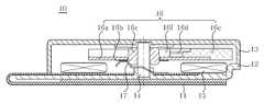
도 1은 종래기술에 따른 SMD 타입 진동모터의 단면도이고, 이를 참조하여 종래기술의 문제점을 설명한다.1 is a cross-sectional view of a SMD type vibration motor according to the prior art, with reference to this will be described the problems of the prior art.
도 1에 도시된 바와 같이, 종래기술에 따른 SMD 타입 진동모터(10)는 인쇄회로기판(11)이 고정된 브라켓(12)과 상기 브라켓(12)의 상부를 커버하며 내부공간을 구획하는 케이스(13), 브라켓(12)에 의해 지지되는 샤프트(14), 브라켓(12)의 상면에 설치된 스테이터(15)인 마그네트 및 샤프트(14)에 회전가능하도록 편심되게 설치된 로터(16)를 포함하는 구성이다.As shown in FIG. 1, the SMD
여기서, 로터(16)는 하면에 정류자(16b)가 형성된 상부기판(16a), 샤프트(14)에 회전가능하게 지지되는 베어링(16c), 상부기판(16a)의 상면에 구비된 코일(16d)과 중량체(16e) 및 상기 상부기판(16a), 코일(16d), 중량체(16e)를 일체로 연결하는 몰딩부재(16f)를 포함한다.Here, the
또한, 인쇄회로기판(11)에는 브러시(17)의 일측이 용접 접속되는데, 브러시(17)의 타측은 정류자(16b)에 접속되어 외부전원을 코일(16d)로 전달한다.In addition, one side of the
이러한 구조를 체용하는 SMD 타입 진동모터(10)는 외부전원이 인쇄회로기판(11)→브러시(17)→정류자(16b)를 통해서 코일(16d)로 공급되면, 코일(16d)과 스테이터(15) 사이에 형성되는 전자기력에 의하여 로터(16)가 회전하면서 진동을 발생시키게 된다.SMD
그런데, 종래기술에 따른 SMD 타입 진동모터(10)는 브라켓(12)을 인쇄회로기판(11)에 고정할 때 양면 테이프나 본드로 고정하므로 견고하게 고정되지 않아 로터(16)의 회전 진동력이 감소되거나, 회전 진동력으로 인해 브라켓(12)이 인쇄회로기판(11)으로부터 분리되는 문제점이 존재한다.However, the SMD
또한, 종래기술에 따른 SMD 타입 진동모터(10)는 모터 회전시 발생하는 전자파 노이즈를 저감시킬 수 있는 어떠한 수단도 구비하지 못한 문제점이 존재한다.In addition, the conventional SMD-
게다가, 휴대전화 셋 등의 PCB에 인쇄회로기판(11)의 외부전원 연결단자 만을 솔더링하여 고정하므로 고정력이 약해서 진동이 발생할 때나 충격을 받았을 때 분리될 우려가 있고, 로터(16)에서 발생하는 진동력을 휴대전화 셋 등에 확실히 전달할 수 없는 문제점이 존재한다.
In addition, since only the external power connection terminal of the printed
본 발명은 상기와 같은 문제점을 해결하기 위하여 안출된 것으로서, 본 발명의 목적은 단자부와 연결되는 접촉부를 채용함으로써 브라켓과 인쇄회로기판의 사이의 결합력을 높이고, 전자파 노이즈를 저감시킬 수 있는 편평형 진동모터를 제공하기 위한 것이다.
The present invention has been made to solve the above problems, an object of the present invention is to adopt a contact portion connected to the terminal portion to increase the coupling force between the bracket and the printed circuit board, a flat vibration motor that can reduce electromagnetic noise It is to provide.
본 발명의 바람직한 제1 실시예에 따른 편평형 진동모터는 중앙에 샤프트의 일단이 삽입되어 고정된 브라켓, 외부전기를 공급받는 단자부가 구비되고, 상기 브라켓의 측면에 배치된 인쇄회로기판, 상기 인쇄회로기판의 상면에 배치된 스테이터, 상기 샤프트에 회전가능하게 설치되어 상기 스테이터와의 상호 작용에 의하여 회전하면서 진동을 발생시키는 로터 및 상기 샤프트의 타단에 설치된 스토퍼를 포함하고, 상기 브라켓과 상기 샤프트는 상기 단자부와 통전되는 것을 특징으로 한다.The flat vibration motor according to the first embodiment of the present invention includes a bracket having one end of a shaft inserted in the center thereof and a terminal portion receiving external electricity, and a printed circuit board disposed on a side of the bracket, and the printed circuit. A stator disposed on an upper surface of the substrate, a rotor rotatably installed on the shaft, the rotor rotating by interaction with the stator, and a stopper installed at the other end of the shaft, wherein the bracket and the shaft It is characterized in that it is energized with the terminal.
여기서, 상기 브라켓 또는 상기 샤프트는 외부전원 연결단자로 이용되는 것을 특징으로 한다.Here, the bracket or the shaft is characterized in that used as an external power connection terminal.
또한, 상기 단자부에 연결되도록 상기 인쇄회로기판에 구비되어, 상기 브라켓과 접촉하여 통전하는 접촉부를 더 포함하는 것을 특징으로 한다.In addition, the printed circuit board is provided to be connected to the terminal portion, characterized in that it further comprises a contact portion for energizing in contact with the bracket.
또한, 상기 접촉부는 상기 단자부 중 마이너스 단자에 연결되는 것을 특징으로 한다.In addition, the contact portion is characterized in that connected to the negative terminal of the terminal portion.
또한, 상기 인쇄회로기판은 중앙에 개구부가 형성되고, 상기 접촉부는 상기 개구부를 둘러싸도록 구비되며, 상기 브라켓은 평판부와 상기 개구부에 대응하도록 상기 평판부의 중앙으로부터 하부로 돌출된 돌출부를 포함하고, 상기 돌출부는 상기 개구부에 삽입되어 고정되며 상기 평판부는 상기 접촉부와 접촉되는 것을 특징으로 한다.In addition, the printed circuit board has an opening formed at the center thereof, the contact portion is provided to surround the opening, and the bracket includes a flat portion and a protrusion protruding downward from the center of the flat portion so as to correspond to the opening. The protrusion is inserted into the opening and fixed, and the flat plate is in contact with the contact portion.
또한, 상기 로터는, 상기 샤프트의 외주면에 회전가능하게 삽입된 베어링, 하면에 정류자가 구비되고, 중심부에 상기 베어링이 삽입된 상부기판 및 상기 베어링에 고정된 로터지지체의 하면에 지지되어 상기 상부기판의 상면에 배치된 권선코일과 중량체를 포함하고, 일단이 상기 단자부에 고정되고, 타단이 상기 정류자에 접촉되는 브러시를 더 포함하는 것을 특징으로 한다.
The rotor may include a bearing rotatably inserted into an outer circumferential surface of the shaft, a commutator disposed on a lower surface thereof, and supported by a lower surface of the upper substrate into which the bearing is inserted and a lower surface of the rotor support fixed to the bearing. It includes a winding coil and a weight body disposed on the upper surface, one end is fixed to the terminal portion, the other end is characterized in that it further comprises a brush in contact with the commutator.
본 발명의 바람직한 제2 실시예에 따른 편평형 진동모터는 중앙에 샤프트의 일단이 삽입되어 고정된 브라켓, 외부전기를 공급받는 단자부가 구비되고, 상기 브라켓의 측면에 배치된 인쇄회로기판, 상기 인쇄회로기판의 상면에 배치된 스테이터, 상기 샤프트에 회전가능하게 설치되어 상기 스테이터와의 상호 작용에 의하여 회전하면서 진동을 발생시키는 로터 및 상기 로터를 커버하는 내부공간을 마련하는 케이스를 포함하고, 상기 브라켓과 상기 샤프트는 상기 단자부와 통전되는 것을 특징으로 한다.The flat vibration motor according to the second embodiment of the present invention includes a bracket in which one end of the shaft is inserted and fixed in the center, a terminal part receiving external electricity, and a printed circuit board disposed on a side of the bracket, the printed circuit. A stator disposed on an upper surface of the substrate, a case rotatably installed on the shaft to provide a rotor that rotates by interaction with the stator to generate vibrations, and an inner space that covers the rotor, wherein the bracket and The shaft is characterized in that the current is supplied to the terminal portion.
여기서, 상기 브라켓 또는 상기 샤프트는 외부전원 연결단자로 이용되는 것을 특징으로 한다.Here, the bracket or the shaft is characterized in that used as an external power connection terminal.
또한, 상기 단자부에 연결되도록 상기 인쇄회로기판에 구비되어, 상기 브라켓과 접촉하여 통전하는 접촉부를 더 포함하는 것을 특징으로 한다.In addition, the printed circuit board is provided to be connected to the terminal portion, characterized in that it further comprises a contact portion for energizing in contact with the bracket.
또한, 상기 접촉부는 상기 단자부 중 마이너스 단자에 연결되는 것을 특징으로 한다.In addition, the contact portion is characterized in that connected to the negative terminal of the terminal portion.
또한, 상기 인쇄회로기판은 중앙에 개구부가 형성되고, 상기 접촉부는 상기 개구부를 둘러싸도록 구비되며, 상기 브라켓은 평판부와 상기 개구부에 대응하도록 상기 평판부의 중앙으로부터 하부로 돌출된 돌출부를 포함하고, 상기 돌출부는 상기 개구부에 삽입되어 고정되며 상기 평판부는 상기 접촉부와 접촉되는 것을 특징으로 한다.In addition, the printed circuit board has an opening formed at the center thereof, the contact portion is provided to surround the opening, and the bracket includes a flat portion and a protrusion protruding downward from the center of the flat portion so as to correspond to the opening. The protrusion is inserted into the opening and fixed, and the flat plate is in contact with the contact portion.
또한, 상기 로터는, 상기 샤프트의 외주면에 회전가능하게 삽입된 베어링, 하면에 정류자가 구비된 상부기판, 상기 상부기판의 상면에 구비된 권선코일과 중량체 및 상기 상부기판, 상기 권선코일 및 상기 중량체를 일체로 연결하는 몰딩부재를 포함하고, 일단이 상기 단자부에 고정되고, 타단이 상기 정류자에 접촉되는 브러시를 더 포함하는 것을 특징으로 한다.
The rotor may include a bearing rotatably inserted into an outer circumferential surface of the shaft, an upper substrate provided with a commutator on a lower surface thereof, a winding coil and a weight body provided on an upper surface of the upper substrate, and the upper substrate, the winding coil, and the It includes a molding member for integrally connecting the weight body, one end is fixed to the terminal portion, the other end is characterized in that it further comprises a brush in contact with the commutator.
본 발명의 특징 및 이점들은 첨부도면에 의거한 다음의 상세한 설명으로부터 더욱 명백해질 것이다.The features and advantages of the present invention will become more apparent from the following detailed description based on the accompanying drawings.
이에 앞서 본 명세서 및 청구범위에 사용된 용어나 단어는 통상적이고 사전적인 의미로 해석되어서는 아니되며, 발명자가 그 자신의 발명을 가장 최선의 방법 으로 설명하기 위해 용어의 개념을 적절하게 정의할 수 있다는 원칙에 입각하여 본 발명의 기술적 사상에 부합되는 의미와 개념으로 해석되어야만 한다.
Prior to this, the terms or words used in this specification and claims are not to be interpreted in a conventional and dictionary sense, and the inventors may appropriately define the concept of terms in order to best describe their invention. It should be interpreted as meaning and concept corresponding to the technical idea of the present invention based on the principle that the present invention.
본 발명에 따르면, 인쇄회로기판의 단자부와 연결되는 접촉부를 구비하여 브라켓을 접촉부에 접촉시킴으로써 브라켓과 인쇄회로기판 사이의 결합력을 증가시켜 브라켓이 인쇄회로기판으로부터 분리되는 문제점을 방지할 수 있는 효과가 있다.According to the present invention, by providing a contact portion connected to the terminal portion of the printed circuit board by contacting the bracket to the contact portion to increase the coupling force between the bracket and the printed circuit board to prevent the problem that the bracket is separated from the printed circuit board have.
또한, 본 발명에 따르면, 접촉부를 통해서 마이너스 단자를 브라켓과 샤프트에 통전시킴으로써 브라켓 또는 샤프트를 외부전원 연결단자로 이용할 수 있고, 모터 회전시 발생하는 전자파 노이즈를 저감시킬 수 있는 장점이 있다.In addition, according to the present invention, by applying a negative terminal to the bracket and the shaft through the contact portion, it is possible to use the bracket or shaft as an external power supply connection terminal, there is an advantage that can reduce the electromagnetic noise generated when the motor rotates.
또한, 본 발명에 따르면, 브라켓 또는 샤프트를 외부전원 연결단자로 이용하므로, 브라켓을 휴대전화 셋(set) 등의 PCB에 솔더링(soldering)하여 연결시킴으로써 로터에서 발생하는 진동력을 휴대전화 셋 등에 확실히 전달할 수 있고 수명을 연장시킬 수 있는 효과가 있다.
In addition, according to the present invention, since the bracket or shaft is used as an external power connection terminal, the vibration force generated in the rotor is surely connected to the cellular phone set by soldering the bracket to a PCB such as a cellular phone set. It can deliver and prolong the life.
도 1은 종래기술에 따른 브러시 타입의 편평형 진동모터의 단면도;
도 2는 본 발명의 바람직한 제1 실시예에 따른 편평형 진동모터의 단면도;
도 3은 도 2에 도시된 인쇄회로기판, 브라켓 및 샤프트의 결합관계를 나타내는 분해사시도;
도 4는 도 2에 도시된 인쇄회로기판, 브라켓 및 샤프트의 결합관계를 나타내는 저면 분해사시도;
도 5는 도 2에 도시된 인쇄회로기판, 브라켓 및 샤프트의 결합관계를 나타내는 결합사시도; 및
도 6은 본 발명의 바람직한 제2 실시예에 따른 편평형 진동모터의 단면도이다.1 is a cross-sectional view of a brush-type flat vibration motor according to the prior art;
2 is a cross-sectional view of a flat vibration motor according to a first preferred embodiment of the present invention;
3 is an exploded perspective view illustrating a coupling relationship between a printed circuit board, a bracket, and a shaft illustrated in FIG. 2;
4 is an exploded bottom perspective view illustrating a coupling relationship between the printed circuit board, the bracket, and the shaft illustrated in FIG. 2;
5 is a perspective view showing a coupling relationship between the printed circuit board, the bracket and the shaft shown in FIG. And
6 is a cross-sectional view of a flat vibration motor according to a second preferred embodiment of the present invention.
본 발명의 목적, 특정한 장점들 및 신규한 특징들은 첨부된 도면들과 연관되어지는 이하의 상세한 설명과 바람직한 실시예들로부터 더욱 명백해질 것이다. 본 명세서에서 각 도면의 구성요소들에 참조번호를 부가함에 있어서, 동일한 구성 요소들에 한해서는 비록 다른 도면상에 표시되더라도 가능한 한 동일한 번호를 가지도록 하고 있음에 유의하여야 한다. 또한, "상면", "일단", "타단" 등의 용어는 하나의 구성요소를 다른 구성요소로부터 구별하기 위해 사용되는 것으로, 구성요소가 상기 용어들에 의해 제한되는 것은 아니다. 그리고, 본 발명을 설명함에 있어서, 본 발명의 요지를 불필요하게 흐릴 수 있는 관련된 공지 기술에 대한 상세한 설명은 생략하도록 한다.
The objects, specific advantages and novel features of the present invention will become more apparent from the following detailed description and the preferred embodiments associated with the accompanying drawings. It should be noted that, in the present specification, the reference numerals are added to the constituent elements of the drawings, and the same constituent elements are assigned the same number as much as possible even if they are displayed on different drawings. In addition, terms such as "top", "end", "other end", etc. are used to distinguish one component from another component, and the component is not limited by the terms. In the following description of the present invention, a detailed description of related arts which may unnecessarily obscure the gist of the present invention will be omitted.
이하, 첨부된 도면을 참조하여 본 발명의 바람직한 실시예를 상세히 설명하기로 한다.
Hereinafter, exemplary embodiments of the present invention will be described in detail with reference to the accompanying drawings.
도 2는 본 발명의 바람직한 제1 실시예에 따른 편평형 진동모터의 단면도이고, 도 3은 도 2에 도시된 인쇄회로기판, 브라켓 및 샤프트의 결합관계를 나타내는 분해사시도이고, 도 4는 도 2에 도시된 인쇄회로기판, 브라켓 및 샤프트의 결합관계를 나타내는 저면 분해사시도이며, 도 5는 도 2에 도시된 인쇄회로기판, 브라켓 및 샤프트의 결합관계를 나타내는 결합사시도이다.
2 is a cross-sectional view of a flat vibration motor according to a first preferred embodiment of the present invention, FIG. 3 is an exploded perspective view showing a coupling relationship between a printed circuit board, a bracket, and a shaft shown in FIG. 2, and FIG. 5 is a bottom exploded perspective view illustrating a coupling relationship of a printed circuit board, a bracket, and a shaft, and FIG. 5 is a perspective view showing a coupling relationship of a printed circuit board, a bracket, and a shaft of FIG. 2.
도 2 내지 도 5에 도시된 바와 같이, 본 실시예에 따른 편평형 진동모터(100)는 중앙에 샤프트(140)의 일단이 삽입되어 고정된 브라켓(150), 외부전기를 공급받는 단자부(130)가 구비되고, 브라켓(150)의 측면에 배치된 인쇄회로기판(110), 인쇄회로기판(110)의 상면에 배치된 스테이터(160), 샤프트(140)에 회전가능하게 설치되어 스테이터(160)와의 상호 작용에 의하여 회전하면서 진동을 발생시키는 로터(170) 및 샤프트(140)의 타단에 설치된 스토퍼(180)를 포함하는 구성이고, 브라켓(150)과 샤프트(140)는 단자부(130)와 통전되는 것을 특징으로 한다.
As shown in FIGS. 2 to 5, the
상기 인쇄회로기판(110)은 외부전기를 공급받는 단자부(130)를 구비하여 전원을 공급하는 역할을 수행한다. 또한, 인쇄회로기판(110)의 상면에는 단자부(130)와 연결되는 접촉부(120; 도 3 참조)가 구비되고, 접촉부(120)는 브라켓(150)과 접촉됨으로써 단자부(130)와 브라켓(150)은 통전하게 된다(도 5 참조). 여기서, 단자부(130)는 플러스 단자(133)와 마이너스 단자(135)로 구분되므로 접촉부(120)는 필요에 따라 플러스 단자(133)와 마이너스 단자(135) 중 어느 하나를 선택하여 연결할 수 있지만, 모터 회전시 발생하는 전자파 노이즈를 저감시킬 수 있는 효과를 극대화하기 위해서 접촉부(120)는 마이너스 단자(135)에 연결하는 것이 바람직하다. 이때, 플러스 단자(133)는 인쇄회로기판(110)의 하면에 구비된 별도의 외부전원 연결단자(137)와 전기적으로 연결된다(도 3 내지 도 4 참조).
The printed
상기 브라켓(150)은 샤프트(140)를 지지하는 역할을 수행하는 것으로, 중앙에 상방향으로 돌출된 버링부(153)가 형성되고 버링부(153)에 샤프트(140)의 일단이 삽입되어 고정된다. 또한, 브라켓(150)은 전술한 바와 같이 인쇄회로기판(110)에 구비된 접촉부(120)에 접촉하여 단자부(130)와 통전됨으로써 전자파 노이즈를 저감시킬 수 있을 뿐만 아니라, 외부전원 연결단자로 이용할 수 있다. 접촉부(120)와 브라켓(150)의 접촉관계를 더욱 구체적으로 살펴보면(도 3 내지 도 5 참조), 접촉부(120)는 인쇄회로기판(110)의 중앙에 형성된 개구부(115)를 둘러싸도록 구비되고, 브라켓(150)은 평판부(157)와, 개구부(115)에 대응하도록 평판부(157)의 중앙으로부터 하부로 돌출된 돌출부(155; 도 4 참조)로 구성되어, 브라켓(150)의 돌출부(155)가 인쇄회로기판(110)의 개구부(115)에 삽입고정됨으로써 브라켓(150)의 평판부(157)와 인쇄회로기판(110)의 접촉부(120)는 접촉하게 된다(도 5 참조).The
한편, 브라켓(150)의 버링부(153)에 고정된 샤프트(140)는 브라켓(150)과 통전되므로, 결국 인쇄회로기판(110)의 단자부(130)는 브라켓(150)을 통해서 샤프트(140)와도 통전되어 전자파 노이즈를 더욱 효과적으로 저감시킬 수 있고, 샤프트(140)를 외부전원 연결단자로 이용할 수 있다.On the other hand, since the
종래기술에 따른 편평형 진동모터와 달리 본 실시예에 따른 편평형 진동모터(100)는 인쇄회로기판(110)의 접촉부(120)를 채용함으로써 브라켓(150)과 샤프트(140)를 인쇄회로기판(110)의 단자부(130)와 통전시켜 외부전원 연결단자로 이용할 수 있고 전자파 노이즈를 저감시킬 수 있을 뿐만 아니라, 브라켓(150)을 인쇄회로기판(110)의 접촉부(120)에 용접으로 결합시킴으로써 인쇄회로기판(110)과 브라켓(150) 사이의 결합력을 높일 수 있다. 또한, 브라켓(150) 또는 샤프트(140)를 외부전원 연결단자로 이용하므로, 기존의 외부전원 연결단자(137)뿐 만아니라 브라켓(150)이나 샤프트(140)를 휴대전화 셋(set) 등의 PCB에 솔더링(soldering)으로 연결시킴으로써 로터(170)에서 발생하는 진동력을 휴대전화 셋 등에 확실히 전달할 수 있고 편평형 진동모터(100)의 수명을 연장시킬 수 있는 효과가 있다.
Unlike the flat vibration motor according to the prior art, the
상기 스테이터(160)는 마그네트이고, 소정 세기의 자기장을 발생시켜 권선코일(175)과의 상호 작용에 로터(170)를 회전운동시키는 역할을 수행하는 것으로, 권선코일(175)과 대향되게 부착된다. 여기서, 스테이터(160)는 브라켓(150)에 수직하게 고정된 샤프트(140)를 중심으로 환형 배치되며, 원주방향으로 복수의 자극을 갖도록 교대로 착자된 영구자석으로 구성된다. 또한, 인쇄회로기판(110)의 상면에 본딩재 등을 매개로 하여 본딩접착된다.
The
상기 스토퍼(180)는 로터(170)의 회전운동에 따라 로터(170)가 부상하는 것을 방지하기 위한 것으로서, 샤프트(140)의 타단에 설치된다. 여기서, 스토퍼(180)는 베어링(171)의 외주면에 고정된 로터지지체(172)와 접촉되는 것을 방지하기 위해서 그 외경이 베어링(171)의 내경보다 작은 원판부 형상을 가지며, 금속재질로 형성하는 것이 바람직하다. 또한, 스토퍼(180)는 로터(170)의 부상을 방지할 수 있도록 샤프트(140)의 타단에 견고히 결합되는 것이 바람직하며, 이를 위해 용접결합, 나사결합 또는 코킹(cauking)결합 등을 이용할 수 있다.
The
상기 로터(170)는 편심회전되어 진동을 발생시키는 역할을 수행하는 것으로, 베어링(171), 상부기판(173), 권선코일(175) 및 중량체(177)를 포함하는 구성이다.
The
상기 베어링(171)은 샤프트(140)에 회전가능하게 지지된 것으로, 샤프트(140)의 외주면에 회전가능하게 삽입된다. 여기서, 윤활성분이 샤프트(140)와 베어링(171) 사이에 개재될 수 있다.
The
상기 상부기판(173)은 로터(170)의 구성요소를 지지하고, 권선코일(175)에 전원을 전달하는 역할을 수행한다. 여기서, 상부기판(173)은 일부가 절개되어 편심되도록 형성된 원형 평판 형상이고, 중심부에 샤프트(140) 및 베어링(171)이 삽입되는 관통홀이 형성된다. 또한, 상부기판(173)의 하면에는 복수의 세그먼트(segment)로 분할된 정류자(179)가 관통홀을 중심으로 환형을 이루도록 배치된다. 정류자(179)는 후술할 브러시(190)와 접촉하여 권선코일(175)에 전원을 전달하는 역할을 수행하며, 패턴인쇄 또는 도금 등의 방법으로 형성된다.
The
상기 권선코일(175)은 전원 인가시 일정세기의 전기장을 발생시키는 역할을 수행하는 것으로, 브러시(190)와 접촉된 정류자(179)를 통해서 전원이 인가되면 전기장을 발생시켜 스테이터(160)에서 발생하는 자기장의 상호작용에 의해 전자기력을 발생시켜 로터(170)를 회전시키게 된다.
The winding
상기 중량체(177)는 로터(170)가 편심 회전될 수 있도록 일정한 질량을 부가하는 역할을 수행한다. 여기서, 중량체(177)는 스테이터(160)에 대한 자력의 영향을 받지 않도록 비자성계 소재이면서 비중이 큰 것이 바람직하고, 예를 들어 텅스텐(W)으로 이루어진다.
The
한편, 권선코일(175) 및 중량체(177)는 로터지지체(172)의 하면에 의해서 지지되어 상부기판(173)의 상면에 배치된다. 여기서, 로터지지체(172)에 베어링(171)을 억지끼움(압입)으로 고정시키고, 추가로 용접을 할 수도 있다. 본 실시예에 따른 편평형 진동모터(100)는 별도의 케이스를 구비하지 않고, 로터지지체(172)가 케이스의 역할을 동시에 수행함으로써, 재료비를 절감할 수 있고 케이스에 의한 공간 제약이 사라져 공간활용성을 높일 수 있을 뿐만 아니라 편평형 진동모터(100)의 박형화를 구현할 수 있다.
On the other hand, the winding
또한, 일단이 인쇄회로기판(110)의 단자부(130)에 고정되고 타단이 상부기판(173)의 하면에 형성된 정류자(179)와 탄성적으로 접촉되는 브러시(190)가 구비되는데, 브러시(190)는 정류자(179)에 전원을 인가하는 역할을 수행한다. 여기서, 브러시(190)는 정류자(179)의 세그먼트에 서로 다른 극성의 전류를 공급하도록 한쌍으로 이루어져 각각 양극(+)과 음극(-)이 흐른다.
In addition, a
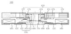
도 6은 본 발명의 바람직한 제2 실시예에 따른 편평형 진동모터의 단면도이다.6 is a cross-sectional view of a flat vibration motor according to a second preferred embodiment of the present invention.
도 6에 도시된 바와 같이, 전술한 제1 실시예에 따른 편평형 진동모터(100)와 본 실시예에 따른 편평형 진동모터(200)의 가장 큰 차이점은 케이스(185)의 구비유무이다. 즉, 제1 실시예에 따른 편평형 진동모터(100)는 케이스(185)를 구비하지 않은 반면, 본 실시예에 따른 편평형 진동모터(200)는 케이스(185)를 구비한다. 케이스(185)의 구비유무를 제외한 나머지 구성요소는 제1 실시예와 유사하므로 중복되는 설명은 생략하고 차이점을 중심으로 기술하도록 한다.
As shown in FIG. 6, the biggest difference between the
케이스(185)는 로터(170), 샤프트(140) 등을 외부로부터 보호하는 역할을 수행하도록 로터(170)를 커버하여 로터(170)의 회전공간을 제공하는 수용부재이다. 여기서, 케이스(185)는 스테이터(160)와 로터(170)의 권선코일(175)에서 발생하는 자속의 자로를 형성하도록 상당한 투자율을 가지며, 외력에 의한 변형으로 로터(170)를 구속하지 않도록 강도가 큰 자성체의 재질로 형성된다. 이때, 케이스(185)의 내측 중심에는 로터(170)와 직접 마찰되는 것을 방지할 수 있는 마찰저감부재(187)를 구비하는 것이 바람직하다.
The
또한, 로터(170)는 하면에 정류자(179)가 구비된 상부기판(173), 샤프트(140)의 일면에 회전가능하게 삽입된 베어링(171), 상부기판(173)의 상면에 구비된 권선코일(175)과 중량체(177), 및 상기 상부기판(173), 권선코일(175), 중량체(177)를 일체로 연결하는 몰딩부재(178)를 포함한다.
In addition, the
또한, 본 실시예에 따른 편평형 진동모터(200)는 전술한 제1 실시예에 따른 편평형 진동모터(100)와 마찬가지로, 인쇄회로기판(110)의 접촉부(120)를 채용함으로써 브라켓(150)과 샤프트(140)를 인쇄회로기판(110)의 단자부(130)와 통전시켜 외부전원 연결단자로 이용할 수 있고 전자파 노이즈를 저감시킬 수 있을 뿐만 아니라 인쇄회로기판(110)과 브라켓(150) 사이의 결합력을 높일 수 있다(도 3 내지 도 5 참조).
In addition, the
본 발명에 따른 편평형 진동모터는 전술한 바와 같이, 반드시 브러시(brush) 타입에 한정되는 것은 아니고, 브러시리스(brushless) 타입에도 동일하게 적용될 수 있다. 브러시리스 타입의 경우 브러시와 정류자가 포함된 상부기판이 없고, 구동 IC가 인쇄회로기판의 상면에 납땜으로 고정된다. 또한, 스테이터로 권선코일이 인쇄회로기판에 고정되고, 로터에 마그네트가 회전가능하게 구비된다. 즉, 브러시리스 타입은 브러시 타입과 비교하였을 때 권선코일과 마그네트의 위치가 서로 바뀐 것이다. 전술한 차이점을 제외하고 브러시리스 타입에서도 브러시 타입과 마찬가지로, 브라켓과 샤프트를 인쇄회로기판의 단자부와 통전시킴으로써 브라켓과 샤프트를 외부전원 연결단자로 이용할 수 있고 전자파 노이즈를 저감시킬 수 있을 뿐만 아니라 인쇄회로기판과 브라켓 사이의 결합력을 높일 수 있다
As described above, the flat vibration motor according to the present invention is not limited to a brush type, but may also be applied to a brushless type. In the brushless type, there is no upper board including a brush and a commutator, and the driving IC is fixed to the upper surface of the printed circuit board by soldering. In addition, the winding coil is fixed to the printed circuit board by the stator, and the magnet is rotatably provided in the rotor. That is, compared to the brush type, the brushless type is the winding coil and the magnet positions are changed. Except for the differences described above, the brushless type is similar to the brush type, and the bracket and the shaft are energized with the terminal portion of the printed circuit board so that the bracket and the shaft can be used as the external power connection terminals and the electromagnetic noise can be reduced as well as the printed circuit. Adhesion between board and bracket can be increased
이상 본 발명을 구체적인 실시예를 통하여 상세히 설명하였으나, 이는 본 발명을 구체적으로 설명하기 위한 것으로, 본 발명에 따른 편평형 진동모터(100, 200)는 이에 한정되지 않으며, 본 발명의 기술적 사상 내에서 당해 분야의 통상의 지식을 가진 자에 의해 그 변형이나 개량이 가능함은 명백하다고 할 것이다. 본 발명의 단순한 변형 내지 변경은 모두 본 발명의 영역에 속하는 것으로 본 발명의 구체적인 보호 범위는 첨부된 특허청구범위에 의하여 명확해질 것이다.
Although the present invention has been described in detail with reference to specific embodiments, it is intended to describe the present invention in detail, and the
100, 200: 편평형 진동모터110: 인쇄회로기판
115: 개구부120: 접촉부
130: 단자부133: 플러스 단자
135: 마이너스 단자137: 외부전원 연결단자
140: 샤프트150: 브라켓
153: 버링부155: 돌출부
157: 평판부160: 스테이터
170: 로터171: 베어링
172: 로터지지체173: 상부기판
175: 권선코일177: 중량체
178: 몰딩부재179: 정류자
180: 스토퍼185: 케이스
187: 마찰저감부재190: 브러시100, 200: flat vibration motor 110: printed circuit board
115: opening 120: contact
130: terminal 133: positive terminal
135: negative terminal 137: external power connection terminal
140: shaft 150: bracket
153: Burring portion 155: protrusion
157: flat plate portion 160: stator
170: rotor 171: bearing
172: rotor support 173: upper substrate
175: winding coil 177: weight
178: molding member 179: commutator
180: stopper 185: case
187: friction reducing member 190: brush
Claims (12)
Translated fromKorean외부전기를 공급받는 단자부가 구비되고, 상기 브라켓의 측면에 배치된 인쇄회로기판;
상기 인쇄회로기판의 상면에 배치된 스테이터;
상기 샤프트에 회전가능하게 설치되어 상기 스테이터와의 상호 작용에 의하여 회전하면서 진동을 발생시키는 로터; 및
상기 샤프트의 타단에 설치된 스토퍼;
를 포함하고,
상기 브라켓과 상기 샤프트는 상기 단자부와 통전되는 것을 특징으로 하는 편평형 진동모터.
A bracket to which one end of the shaft is inserted and fixed in the center;
A printed circuit board having a terminal unit receiving external electricity and disposed on a side surface of the bracket;
A stator disposed on an upper surface of the printed circuit board;
A rotor rotatably installed on the shaft to generate vibration while rotating by interaction with the stator; And
A stopper installed at the other end of the shaft;
Including,
And the bracket and the shaft are energized with the terminal part.
상기 브라켓 또는 상기 샤프트는 외부전원 연결단자로 이용되는 것을 특징으로 하는 편평형 진동모터.
The method according to claim 1,
The bracket or the shaft is a flat vibration motor, characterized in that used as an external power supply connection terminal.
상기 단자부에 연결되도록 상기 인쇄회로기판에 구비되어, 상기 브라켓과 접촉하여 통전하는 접촉부를 더 포함하는 것을 특징으로 하는 편평형 진동모터.
The method according to claim 1,
And a contact part provided on the printed circuit board so as to be connected to the terminal part, the contact part being in electrical contact with the bracket.
상기 접촉부는 상기 단자부 중 마이너스 단자에 연결되는 것을 특징으로 하는 편평형 진동모터.
The method according to claim 3,
And the contact portion is connected to a negative terminal of the terminal portion.
상기 인쇄회로기판은 중앙에 개구부가 형성되고, 상기 접촉부는 상기 개구부를 둘러싸도록 구비되며,
상기 브라켓은 평판부와 상기 개구부에 대응하도록 상기 평판부의 중앙으로부터 하부로 돌출된 돌출부를 포함하고, 상기 돌출부는 상기 개구부에 삽입되어 고정되며 상기 평판부는 상기 접촉부와 접촉되는 것을 특징으로 하는 평편형 진동모터.
The method according to claim 3,
The printed circuit board has an opening formed in the center thereof, and the contact portion is provided to surround the opening.
The bracket includes a flat plate and a protrusion protruding downward from the center of the flat plate to correspond to the opening, wherein the protrusion is inserted into and fixed to the opening, and the flat plate is in contact with the contact portion. motor.
상기 로터는,
상기 샤프트의 외주면에 회전가능하게 삽입된 베어링;
하면에 정류자가 구비되고, 중심부에 상기 베어링이 삽입된 상부기판; 및
상기 베어링에 고정된 로터지지체의 하면에 지지되어 상기 상부기판의 상면에 배치된 권선코일과 중량체를 포함하고,
일단이 상기 단자부에 고정되고, 타단이 상기 정류자에 접촉되는 브러시를 더 포함하는 것을 특징으로 하는 편평형 진동모터.
The method according to claim 1,
The rotor is,
A bearing rotatably inserted into an outer circumferential surface of the shaft;
An upper substrate having a commutator at a lower surface thereof and having the bearing inserted at a center thereof; And
A winding coil and a weight body supported on a lower surface of the rotor support fixed to the bearing and disposed on an upper surface of the upper substrate;
One end is fixed to the terminal portion, the other end of the flat vibration motor further comprises a brush in contact with the commutator.
외부전기를 공급받는 단자부가 구비되고, 상기 브라켓의 측면에 배치된 인쇄회로기판;
상기 인쇄회로기판의 상면에 배치된 스테이터;
상기 샤프트에 회전가능하게 설치되어 상기 스테이터와의 상호 작용에 의하여 회전하면서 진동을 발생시키는 로터; 및
상기 로터를 커버하는 내부공간을 마련하는 케이스;
를 포함하고,
상기 브라켓과 상기 샤프트는 상기 단자부와 통전되며,
상기 단자부에 연결되도록 상기 인쇄회로기판에 구비되어, 상기 브라켓과 접촉하여 통전하는 접촉부를 더 포함하는 것을 특징으로 하는 편평형 진동모터.
A bracket to which one end of the shaft is inserted and fixed in the center;
A printed circuit board having a terminal unit receiving external electricity and disposed on a side surface of the bracket;
A stator disposed on an upper surface of the printed circuit board;
A rotor rotatably installed on the shaft to generate vibration while rotating by interaction with the stator; And
A case providing an inner space covering the rotor;
Including,
The bracket and the shaft are energized with the terminal portion,
And a contact part provided on the printed circuit board so as to be connected to the terminal part, the contact part being in electrical contact with the bracket.
상기 브라켓 또는 상기 샤프트는 외부전원 연결단자로 이용되는 것을 특징으로 하는 편평형 진동모터.
The method according to claim 7,
The bracket or the shaft is a flat vibration motor, characterized in that used as an external power supply connection terminal.
상기 접촉부는 상기 단자부 중 마이너스 단자에 연결되는 것을 특징으로 하는 편평형 진동모터.
The method according to claim 7,
And the contact portion is connected to a negative terminal of the terminal portion.
상기 인쇄회로기판은 중앙에 개구부가 형성되고, 상기 접촉부는 상기 개구부를 둘러싸도록 구비되며,
상기 브라켓은 평판부와 상기 개구부에 대응하도록 상기 평판부의 중앙으로부터 하부로 돌출된 돌출부를 포함하고, 상기 돌출부는 상기 개구부에 삽입되어 고정되며 상기 평판부는 상기 접촉부와 접촉되는 것을 특징으로 하는 평편형 진동모터.
The method according to claim 7,
The printed circuit board has an opening formed in the center thereof, and the contact portion is provided to surround the opening.
The bracket includes a flat plate and a protrusion protruding downward from the center of the flat plate to correspond to the opening, wherein the protrusion is inserted into and fixed to the opening, and the flat plate is in contact with the contact portion. motor.
상기 로터는,
상기 샤프트의 외주면에 회전가능하게 삽입된 베어링;
하면에 정류자가 구비된 상부기판;
상기 상부기판의 상면에 구비된 권선코일과 중량체; 및
상기 상부기판, 상기 권선코일 및 상기 중량체를 일체로 연결하는 몰딩부재를 포함하고,
일단이 상기 단자부에 고정되고, 타단이 상기 정류자에 접촉되는 브러시를 더 포함하는 것을 특징으로 하는 편평형 진동모터.The method according to claim 7,
The rotor is,
A bearing rotatably inserted into an outer circumferential surface of the shaft;
An upper substrate provided with a commutator on a lower surface thereof;
A winding coil and a weight body provided on an upper surface of the upper substrate; And
It includes a molding member for connecting the upper substrate, the winding coil and the weight body integrally,
One end is fixed to the terminal portion, the other end of the flat vibration motor further comprises a brush in contact with the commutator.
Priority Applications (3)
| Application Number | Priority Date | Filing Date | Title |
|---|---|---|---|
| KR1020100053457AKR101095099B1 (en) | 2010-06-07 | 2010-06-07 | Flat vibration motor |
| CN201010278489.0ACN102270896B (en) | 2010-06-07 | 2010-09-08 | Flat type vibration motor |
| US12/877,850US8227946B2 (en) | 2010-06-07 | 2010-09-08 | Flat type vibration motor |
Applications Claiming Priority (1)
| Application Number | Priority Date | Filing Date | Title |
|---|---|---|---|
| KR1020100053457AKR101095099B1 (en) | 2010-06-07 | 2010-06-07 | Flat vibration motor |
Publications (2)
| Publication Number | Publication Date |
|---|---|
| KR20110133832A KR20110133832A (en) | 2011-12-14 |
| KR101095099B1true KR101095099B1 (en) | 2011-12-16 |
Family
ID=45053089
Family Applications (1)
| Application Number | Title | Priority Date | Filing Date |
|---|---|---|---|
| KR1020100053457AExpired - Fee RelatedKR101095099B1 (en) | 2010-06-07 | 2010-06-07 | Flat vibration motor |
Country Status (3)
| Country | Link |
|---|---|
| US (1) | US8227946B2 (en) |
| KR (1) | KR101095099B1 (en) |
| CN (1) | CN102270896B (en) |
Families Citing this family (488)
| Publication number | Priority date | Publication date | Assignee | Title |
|---|---|---|---|---|
| US20070084897A1 (en) | 2003-05-20 | 2007-04-19 | Shelton Frederick E Iv | Articulating surgical stapling instrument incorporating a two-piece e-beam firing mechanism |
| US9060770B2 (en) | 2003-05-20 | 2015-06-23 | Ethicon Endo-Surgery, Inc. | Robotically-driven surgical instrument with E-beam driver |
| US8215531B2 (en) | 2004-07-28 | 2012-07-10 | Ethicon Endo-Surgery, Inc. | Surgical stapling instrument having a medical substance dispenser |
| US11890012B2 (en) | 2004-07-28 | 2024-02-06 | Cilag Gmbh International | Staple cartridge comprising cartridge body and attached support |
| US9072535B2 (en) | 2011-05-27 | 2015-07-07 | Ethicon Endo-Surgery, Inc. | Surgical stapling instruments with rotatable staple deployment arrangements |
| US11998198B2 (en) | 2004-07-28 | 2024-06-04 | Cilag Gmbh International | Surgical stapling instrument incorporating a two-piece E-beam firing mechanism |
| US9237891B2 (en) | 2005-08-31 | 2016-01-19 | Ethicon Endo-Surgery, Inc. | Robotically-controlled surgical stapling devices that produce formed staples having different lengths |
| US10159482B2 (en) | 2005-08-31 | 2018-12-25 | Ethicon Llc | Fastener cartridge assembly comprising a fixed anvil and different staple heights |
| US11246590B2 (en) | 2005-08-31 | 2022-02-15 | Cilag Gmbh International | Staple cartridge including staple drivers having different unfired heights |
| US7673781B2 (en) | 2005-08-31 | 2010-03-09 | Ethicon Endo-Surgery, Inc. | Surgical stapling device with staple driver that supports multiple wire diameter staples |
| US7934630B2 (en) | 2005-08-31 | 2011-05-03 | Ethicon Endo-Surgery, Inc. | Staple cartridges for forming staples having differing formed staple heights |
| US7669746B2 (en) | 2005-08-31 | 2010-03-02 | Ethicon Endo-Surgery, Inc. | Staple cartridges for forming staples having differing formed staple heights |
| US11484312B2 (en) | 2005-08-31 | 2022-11-01 | Cilag Gmbh International | Staple cartridge comprising a staple driver arrangement |
| US20070106317A1 (en) | 2005-11-09 | 2007-05-10 | Shelton Frederick E Iv | Hydraulically and electrically actuated articulation joints for surgical instruments |
| US20120292367A1 (en) | 2006-01-31 | 2012-11-22 | Ethicon Endo-Surgery, Inc. | Robotically-controlled end effector |
| US7753904B2 (en) | 2006-01-31 | 2010-07-13 | Ethicon Endo-Surgery, Inc. | Endoscopic surgical instrument with a handle that can articulate with respect to the shaft |
| US8708213B2 (en) | 2006-01-31 | 2014-04-29 | Ethicon Endo-Surgery, Inc. | Surgical instrument having a feedback system |
| US9861359B2 (en) | 2006-01-31 | 2018-01-09 | Ethicon Llc | Powered surgical instruments with firing system lockout arrangements |
| US8186555B2 (en) | 2006-01-31 | 2012-05-29 | Ethicon Endo-Surgery, Inc. | Motor-driven surgical cutting and fastening instrument with mechanical closure system |
| US8820603B2 (en) | 2006-01-31 | 2014-09-02 | Ethicon Endo-Surgery, Inc. | Accessing data stored in a memory of a surgical instrument |
| US11224427B2 (en) | 2006-01-31 | 2022-01-18 | Cilag Gmbh International | Surgical stapling system including a console and retraction assembly |
| US20110295295A1 (en) | 2006-01-31 | 2011-12-01 | Ethicon Endo-Surgery, Inc. | Robotically-controlled surgical instrument having recording capabilities |
| US20110024477A1 (en) | 2009-02-06 | 2011-02-03 | Hall Steven G | Driven Surgical Stapler Improvements |
| US11278279B2 (en) | 2006-01-31 | 2022-03-22 | Cilag Gmbh International | Surgical instrument assembly |
| US11793518B2 (en) | 2006-01-31 | 2023-10-24 | Cilag Gmbh International | Powered surgical instruments with firing system lockout arrangements |
| US7845537B2 (en) | 2006-01-31 | 2010-12-07 | Ethicon Endo-Surgery, Inc. | Surgical instrument having recording capabilities |
| US8236010B2 (en) | 2006-03-23 | 2012-08-07 | Ethicon Endo-Surgery, Inc. | Surgical fastener and cutter with mimicking end effector |
| US8992422B2 (en) | 2006-03-23 | 2015-03-31 | Ethicon Endo-Surgery, Inc. | Robotically-controlled endoscopic accessory channel |
| US8322455B2 (en) | 2006-06-27 | 2012-12-04 | Ethicon Endo-Surgery, Inc. | Manually driven surgical cutting and fastening instrument |
| US10130359B2 (en) | 2006-09-29 | 2018-11-20 | Ethicon Llc | Method for forming a staple |
| US7506791B2 (en) | 2006-09-29 | 2009-03-24 | Ethicon Endo-Surgery, Inc. | Surgical stapling instrument with mechanical mechanism for limiting maximum tissue compression |
| US10568652B2 (en) | 2006-09-29 | 2020-02-25 | Ethicon Llc | Surgical staples having attached drivers of different heights and stapling instruments for deploying the same |
| US11980366B2 (en) | 2006-10-03 | 2024-05-14 | Cilag Gmbh International | Surgical instrument |
| US8652120B2 (en) | 2007-01-10 | 2014-02-18 | Ethicon Endo-Surgery, Inc. | Surgical instrument with wireless communication between control unit and sensor transponders |
| US8632535B2 (en) | 2007-01-10 | 2014-01-21 | Ethicon Endo-Surgery, Inc. | Interlock and surgical instrument including same |
| US8684253B2 (en) | 2007-01-10 | 2014-04-01 | Ethicon Endo-Surgery, Inc. | Surgical instrument with wireless communication between a control unit of a robotic system and remote sensor |
| US11291441B2 (en) | 2007-01-10 | 2022-04-05 | Cilag Gmbh International | Surgical instrument with wireless communication between control unit and remote sensor |
| US20080169333A1 (en) | 2007-01-11 | 2008-07-17 | Shelton Frederick E | Surgical stapler end effector with tapered distal end |
| US11039836B2 (en) | 2007-01-11 | 2021-06-22 | Cilag Gmbh International | Staple cartridge for use with a surgical stapling instrument |
| US7673782B2 (en) | 2007-03-15 | 2010-03-09 | Ethicon Endo-Surgery, Inc. | Surgical stapling instrument having a releasable buttress material |
| US8893946B2 (en) | 2007-03-28 | 2014-11-25 | Ethicon Endo-Surgery, Inc. | Laparoscopic tissue thickness and clamp load measuring devices |
| US8931682B2 (en) | 2007-06-04 | 2015-01-13 | Ethicon Endo-Surgery, Inc. | Robotically-controlled shaft based rotary drive systems for surgical instruments |
| US11564682B2 (en) | 2007-06-04 | 2023-01-31 | Cilag Gmbh International | Surgical stapler device |
| US7753245B2 (en) | 2007-06-22 | 2010-07-13 | Ethicon Endo-Surgery, Inc. | Surgical stapling instruments |
| US8408439B2 (en) | 2007-06-22 | 2013-04-02 | Ethicon Endo-Surgery, Inc. | Surgical stapling instrument with an articulatable end effector |
| US11849941B2 (en) | 2007-06-29 | 2023-12-26 | Cilag Gmbh International | Staple cartridge having staple cavities extending at a transverse angle relative to a longitudinal cartridge axis |
| US8561870B2 (en) | 2008-02-13 | 2013-10-22 | Ethicon Endo-Surgery, Inc. | Surgical stapling instrument |
| US7866527B2 (en) | 2008-02-14 | 2011-01-11 | Ethicon Endo-Surgery, Inc. | Surgical stapling apparatus with interlockable firing system |
| US7819298B2 (en) | 2008-02-14 | 2010-10-26 | Ethicon Endo-Surgery, Inc. | Surgical stapling apparatus with control features operable with one hand |
| US8657174B2 (en) | 2008-02-14 | 2014-02-25 | Ethicon Endo-Surgery, Inc. | Motorized surgical cutting and fastening instrument having handle based power source |
| US8573465B2 (en) | 2008-02-14 | 2013-11-05 | Ethicon Endo-Surgery, Inc. | Robotically-controlled surgical end effector system with rotary actuated closure systems |
| US8758391B2 (en) | 2008-02-14 | 2014-06-24 | Ethicon Endo-Surgery, Inc. | Interchangeable tools for surgical instruments |
| US9179912B2 (en) | 2008-02-14 | 2015-11-10 | Ethicon Endo-Surgery, Inc. | Robotically-controlled motorized surgical cutting and fastening instrument |
| US8636736B2 (en) | 2008-02-14 | 2014-01-28 | Ethicon Endo-Surgery, Inc. | Motorized surgical cutting and fastening instrument |
| US11986183B2 (en) | 2008-02-14 | 2024-05-21 | Cilag Gmbh International | Surgical cutting and fastening instrument comprising a plurality of sensors to measure an electrical parameter |
| JP5410110B2 (en) | 2008-02-14 | 2014-02-05 | エシコン・エンド−サージェリィ・インコーポレイテッド | Surgical cutting / fixing instrument with RF electrode |
| US11272927B2 (en) | 2008-02-15 | 2022-03-15 | Cilag Gmbh International | Layer arrangements for surgical staple cartridges |
| US9585657B2 (en) | 2008-02-15 | 2017-03-07 | Ethicon Endo-Surgery, Llc | Actuator for releasing a layer of material from a surgical end effector |
| US7954686B2 (en) | 2008-09-19 | 2011-06-07 | Ethicon Endo-Surgery, Inc. | Surgical stapler with apparatus for adjusting staple height |
| PL3476312T3 (en) | 2008-09-19 | 2024-03-11 | Ethicon Llc | Surgical stapler with apparatus for adjusting staple height |
| US9005230B2 (en) | 2008-09-23 | 2015-04-14 | Ethicon Endo-Surgery, Inc. | Motorized surgical instrument |
| US8210411B2 (en) | 2008-09-23 | 2012-07-03 | Ethicon Endo-Surgery, Inc. | Motor-driven surgical cutting instrument |
| US9386983B2 (en) | 2008-09-23 | 2016-07-12 | Ethicon Endo-Surgery, Llc | Robotically-controlled motorized surgical instrument |
| US11648005B2 (en) | 2008-09-23 | 2023-05-16 | Cilag Gmbh International | Robotically-controlled motorized surgical instrument with an end effector |
| US8608045B2 (en) | 2008-10-10 | 2013-12-17 | Ethicon Endo-Sugery, Inc. | Powered surgical cutting and stapling apparatus with manually retractable firing system |
| US8517239B2 (en) | 2009-02-05 | 2013-08-27 | Ethicon Endo-Surgery, Inc. | Surgical stapling instrument comprising a magnetic element driver |
| US8453907B2 (en) | 2009-02-06 | 2013-06-04 | Ethicon Endo-Surgery, Inc. | Motor driven surgical fastener device with cutting member reversing mechanism |
| RU2525225C2 (en) | 2009-02-06 | 2014-08-10 | Этикон Эндо-Серджери, Инк. | Improvement of drive surgical suturing instrument |
| US8444036B2 (en) | 2009-02-06 | 2013-05-21 | Ethicon Endo-Surgery, Inc. | Motor driven surgical fastener device with mechanisms for adjusting a tissue gap within the end effector |
| US8220688B2 (en) | 2009-12-24 | 2012-07-17 | Ethicon Endo-Surgery, Inc. | Motor-driven surgical cutting instrument with electric actuator directional control assembly |
| US8851354B2 (en) | 2009-12-24 | 2014-10-07 | Ethicon Endo-Surgery, Inc. | Surgical cutting instrument that analyzes tissue thickness |
| KR101091423B1 (en)* | 2010-06-22 | 2011-12-07 | 엘지이노텍 주식회사 | Linear vibrator |
| US8783543B2 (en) | 2010-07-30 | 2014-07-22 | Ethicon Endo-Surgery, Inc. | Tissue acquisition arrangements and methods for surgical stapling devices |
| US11812965B2 (en) | 2010-09-30 | 2023-11-14 | Cilag Gmbh International | Layer of material for a surgical end effector |
| US9364233B2 (en) | 2010-09-30 | 2016-06-14 | Ethicon Endo-Surgery, Llc | Tissue thickness compensators for circular surgical staplers |
| US9277919B2 (en) | 2010-09-30 | 2016-03-08 | Ethicon Endo-Surgery, Llc | Tissue thickness compensator comprising fibers to produce a resilient load |
| US10945731B2 (en) | 2010-09-30 | 2021-03-16 | Ethicon Llc | Tissue thickness compensator comprising controlled release and expansion |
| US9788834B2 (en) | 2010-09-30 | 2017-10-17 | Ethicon Llc | Layer comprising deployable attachment members |
| US9307989B2 (en) | 2012-03-28 | 2016-04-12 | Ethicon Endo-Surgery, Llc | Tissue stapler having a thickness compensator incorportating a hydrophobic agent |
| US9301753B2 (en) | 2010-09-30 | 2016-04-05 | Ethicon Endo-Surgery, Llc | Expandable tissue thickness compensator |
| US9629814B2 (en) | 2010-09-30 | 2017-04-25 | Ethicon Endo-Surgery, Llc | Tissue thickness compensator configured to redistribute compressive forces |
| US9386988B2 (en) | 2010-09-30 | 2016-07-12 | Ethicon End-Surgery, LLC | Retainer assembly including a tissue thickness compensator |
| US9314246B2 (en) | 2010-09-30 | 2016-04-19 | Ethicon Endo-Surgery, Llc | Tissue stapler having a thickness compensator incorporating an anti-inflammatory agent |
| US12213666B2 (en) | 2010-09-30 | 2025-02-04 | Cilag Gmbh International | Tissue thickness compensator comprising layers |
| US9220501B2 (en) | 2010-09-30 | 2015-12-29 | Ethicon Endo-Surgery, Inc. | Tissue thickness compensators |
| US9301752B2 (en) | 2010-09-30 | 2016-04-05 | Ethicon Endo-Surgery, Llc | Tissue thickness compensator comprising a plurality of capsules |
| RU2013119928A (en) | 2010-09-30 | 2014-11-10 | Этикон Эндо-Серджери, Инк. | A STAPLING SYSTEM CONTAINING A RETAINING MATRIX AND A LEVELING MATRIX |
| US11925354B2 (en) | 2010-09-30 | 2024-03-12 | Cilag Gmbh International | Staple cartridge comprising staples positioned within a compressible portion thereof |
| US9351730B2 (en) | 2011-04-29 | 2016-05-31 | Ethicon Endo-Surgery, Llc | Tissue thickness compensator comprising channels |
| US9332974B2 (en) | 2010-09-30 | 2016-05-10 | Ethicon Endo-Surgery, Llc | Layered tissue thickness compensator |
| US9232941B2 (en) | 2010-09-30 | 2016-01-12 | Ethicon Endo-Surgery, Inc. | Tissue thickness compensator comprising a reservoir |
| US11298125B2 (en) | 2010-09-30 | 2022-04-12 | Cilag Gmbh International | Tissue stapler having a thickness compensator |
| US9055941B2 (en) | 2011-09-23 | 2015-06-16 | Ethicon Endo-Surgery, Inc. | Staple cartridge including collapsible deck |
| US9016542B2 (en) | 2010-09-30 | 2015-04-28 | Ethicon Endo-Surgery, Inc. | Staple cartridge comprising compressible distortion resistant components |
| US8695866B2 (en) | 2010-10-01 | 2014-04-15 | Ethicon Endo-Surgery, Inc. | Surgical instrument having a power control circuit |
| AU2012250197B2 (en) | 2011-04-29 | 2017-08-10 | Ethicon Endo-Surgery, Inc. | Staple cartridge comprising staples positioned within a compressible portion thereof |
| US11207064B2 (en) | 2011-05-27 | 2021-12-28 | Cilag Gmbh International | Automated end effector component reloading system for use with a robotic system |
| US9050084B2 (en) | 2011-09-23 | 2015-06-09 | Ethicon Endo-Surgery, Inc. | Staple cartridge including collapsible deck arrangement |
| KR101240676B1 (en)* | 2011-12-26 | 2013-03-11 | 삼성전기주식회사 | Single phase induction vibration motor |
| US9044230B2 (en) | 2012-02-13 | 2015-06-02 | Ethicon Endo-Surgery, Inc. | Surgical cutting and fastening instrument with apparatus for determining cartridge and firing motion status |
| BR112014024098B1 (en) | 2012-03-28 | 2021-05-25 | Ethicon Endo-Surgery, Inc. | staple cartridge |
| MX358135B (en) | 2012-03-28 | 2018-08-06 | Ethicon Endo Surgery Inc | Tissue thickness compensator comprising a plurality of layers. |
| JP6224070B2 (en) | 2012-03-28 | 2017-11-01 | エシコン・エンド−サージェリィ・インコーポレイテッドEthicon Endo−Surgery,Inc. | Retainer assembly including tissue thickness compensator |
| US9101358B2 (en) | 2012-06-15 | 2015-08-11 | Ethicon Endo-Surgery, Inc. | Articulatable surgical instrument comprising a firing drive |
| US9282974B2 (en) | 2012-06-28 | 2016-03-15 | Ethicon Endo-Surgery, Llc | Empty clip cartridge lockout |
| US12383267B2 (en) | 2012-06-28 | 2025-08-12 | Cilag Gmbh International | Robotically powered surgical device with manually-actuatable reversing system |
| US9408606B2 (en) | 2012-06-28 | 2016-08-09 | Ethicon Endo-Surgery, Llc | Robotically powered surgical device with manually-actuatable reversing system |
| BR112014032776B1 (en) | 2012-06-28 | 2021-09-08 | Ethicon Endo-Surgery, Inc | SURGICAL INSTRUMENT SYSTEM AND SURGICAL KIT FOR USE WITH A SURGICAL INSTRUMENT SYSTEM |
| JP6290201B2 (en) | 2012-06-28 | 2018-03-07 | エシコン・エンド−サージェリィ・インコーポレイテッドEthicon Endo−Surgery,Inc. | Lockout for empty clip cartridge |
| US20140005718A1 (en) | 2012-06-28 | 2014-01-02 | Ethicon Endo-Surgery, Inc. | Multi-functional powered surgical device with external dissection features |
| US9289256B2 (en) | 2012-06-28 | 2016-03-22 | Ethicon Endo-Surgery, Llc | Surgical end effectors having angled tissue-contacting surfaces |
| US11278284B2 (en) | 2012-06-28 | 2022-03-22 | Cilag Gmbh International | Rotary drive arrangements for surgical instruments |
| US20140001231A1 (en) | 2012-06-28 | 2014-01-02 | Ethicon Endo-Surgery, Inc. | Firing system lockout arrangements for surgical instruments |
| US9434640B2 (en) | 2012-12-04 | 2016-09-06 | Guardian Industries Corp. | Method of making heat treated coated article with carbon based coating and protective film |
| US9386984B2 (en) | 2013-02-08 | 2016-07-12 | Ethicon Endo-Surgery, Llc | Staple cartridge comprising a releasable cover |
| RU2672520C2 (en) | 2013-03-01 | 2018-11-15 | Этикон Эндо-Серджери, Инк. | Hingedly turnable surgical instruments with conducting ways for signal transfer |
| US9468438B2 (en) | 2013-03-01 | 2016-10-18 | Eticon Endo-Surgery, LLC | Sensor straightened end effector during removal through trocar |
| BR112015021082B1 (en) | 2013-03-01 | 2022-05-10 | Ethicon Endo-Surgery, Inc | surgical instrument |
| US9345481B2 (en) | 2013-03-13 | 2016-05-24 | Ethicon Endo-Surgery, Llc | Staple cartridge tissue thickness sensor system |
| US9629629B2 (en) | 2013-03-14 | 2017-04-25 | Ethicon Endo-Surgey, LLC | Control systems for surgical instruments |
| US9808244B2 (en) | 2013-03-14 | 2017-11-07 | Ethicon Llc | Sensor arrangements for absolute positioning system for surgical instruments |
| US9332984B2 (en) | 2013-03-27 | 2016-05-10 | Ethicon Endo-Surgery, Llc | Fastener cartridge assemblies |
| US9572577B2 (en) | 2013-03-27 | 2017-02-21 | Ethicon Endo-Surgery, Llc | Fastener cartridge comprising a tissue thickness compensator including openings therein |
| US9795384B2 (en) | 2013-03-27 | 2017-10-24 | Ethicon Llc | Fastener cartridge comprising a tissue thickness compensator and a gap setting element |
| BR112015026109B1 (en) | 2013-04-16 | 2022-02-22 | Ethicon Endo-Surgery, Inc | surgical instrument |
| US9826976B2 (en) | 2013-04-16 | 2017-11-28 | Ethicon Llc | Motor driven surgical instruments with lockable dual drive shafts |
| US9574644B2 (en) | 2013-05-30 | 2017-02-21 | Ethicon Endo-Surgery, Llc | Power module for use with a surgical instrument |
| US9775609B2 (en) | 2013-08-23 | 2017-10-03 | Ethicon Llc | Tamper proof circuit for surgical instrument battery pack |
| MX369362B (en) | 2013-08-23 | 2019-11-06 | Ethicon Endo Surgery Llc | Firing member retraction devices for powered surgical instruments. |
| JP2015047525A (en)* | 2013-08-30 | 2015-03-16 | アルプス電気株式会社 | Vibration generator |
| US9724092B2 (en) | 2013-12-23 | 2017-08-08 | Ethicon Llc | Modular surgical instruments |
| US20150173749A1 (en) | 2013-12-23 | 2015-06-25 | Ethicon Endo-Surgery, Inc. | Surgical staples and staple cartridges |
| US9839428B2 (en) | 2013-12-23 | 2017-12-12 | Ethicon Llc | Surgical cutting and stapling instruments with independent jaw control features |
| US20150173756A1 (en) | 2013-12-23 | 2015-06-25 | Ethicon Endo-Surgery, Inc. | Surgical cutting and stapling methods |
| US9962161B2 (en) | 2014-02-12 | 2018-05-08 | Ethicon Llc | Deliverable surgical instrument |
| US20140166724A1 (en) | 2014-02-24 | 2014-06-19 | Ethicon Endo-Surgery, Inc. | Staple cartridge including a barbed staple |
| JP6462004B2 (en) | 2014-02-24 | 2019-01-30 | エシコン エルエルシー | Fastening system with launcher lockout |
| US10004497B2 (en) | 2014-03-26 | 2018-06-26 | Ethicon Llc | Interface systems for use with surgical instruments |
| BR112016021943B1 (en) | 2014-03-26 | 2022-06-14 | Ethicon Endo-Surgery, Llc | SURGICAL INSTRUMENT FOR USE BY AN OPERATOR IN A SURGICAL PROCEDURE |
| US10013049B2 (en) | 2014-03-26 | 2018-07-03 | Ethicon Llc | Power management through sleep options of segmented circuit and wake up control |
| US20150272580A1 (en) | 2014-03-26 | 2015-10-01 | Ethicon Endo-Surgery, Inc. | Verification of number of battery exchanges/procedure count |
| US9913642B2 (en) | 2014-03-26 | 2018-03-13 | Ethicon Llc | Surgical instrument comprising a sensor system |
| US12232723B2 (en) | 2014-03-26 | 2025-02-25 | Cilag Gmbh International | Systems and methods for controlling a segmented circuit |
| US20150297225A1 (en) | 2014-04-16 | 2015-10-22 | Ethicon Endo-Surgery, Inc. | Fastener cartridges including extensions having different configurations |
| CN106456159B (en) | 2014-04-16 | 2019-03-08 | 伊西康内外科有限责任公司 | Fastener Cartridge Assembly and Nail Retainer Cover Arrangement |
| US10470768B2 (en) | 2014-04-16 | 2019-11-12 | Ethicon Llc | Fastener cartridge including a layer attached thereto |
| BR112016023825B1 (en) | 2014-04-16 | 2022-08-02 | Ethicon Endo-Surgery, Llc | STAPLE CARTRIDGE FOR USE WITH A SURGICAL STAPLER AND STAPLE CARTRIDGE FOR USE WITH A SURGICAL INSTRUMENT |
| CN106456176B (en) | 2014-04-16 | 2019-06-28 | 伊西康内外科有限责任公司 | Fastener Cartridge Including Extensions With Different Configurations |
| US10327764B2 (en) | 2014-09-26 | 2019-06-25 | Ethicon Llc | Method for creating a flexible staple line |
| US10045781B2 (en) | 2014-06-13 | 2018-08-14 | Ethicon Llc | Closure lockout systems for surgical instruments |
| BR112017004361B1 (en) | 2014-09-05 | 2023-04-11 | Ethicon Llc | ELECTRONIC SYSTEM FOR A SURGICAL INSTRUMENT |
| US11311294B2 (en) | 2014-09-05 | 2022-04-26 | Cilag Gmbh International | Powered medical device including measurement of closure state of jaws |
| US10135242B2 (en) | 2014-09-05 | 2018-11-20 | Ethicon Llc | Smart cartridge wake up operation and data retention |
| US10105142B2 (en) | 2014-09-18 | 2018-10-23 | Ethicon Llc | Surgical stapler with plurality of cutting elements |
| CN107427300B (en) | 2014-09-26 | 2020-12-04 | 伊西康有限责任公司 | Surgical suture buttresses and auxiliary materials |
| US11523821B2 (en) | 2014-09-26 | 2022-12-13 | Cilag Gmbh International | Method for creating a flexible staple line |
| US10076325B2 (en) | 2014-10-13 | 2018-09-18 | Ethicon Llc | Surgical stapling apparatus comprising a tissue stop |
| US9924944B2 (en) | 2014-10-16 | 2018-03-27 | Ethicon Llc | Staple cartridge comprising an adjunct material |
| US10517594B2 (en) | 2014-10-29 | 2019-12-31 | Ethicon Llc | Cartridge assemblies for surgical staplers |
| US11141153B2 (en) | 2014-10-29 | 2021-10-12 | Cilag Gmbh International | Staple cartridges comprising driver arrangements |
| US9844376B2 (en) | 2014-11-06 | 2017-12-19 | Ethicon Llc | Staple cartridge comprising a releasable adjunct material |
| US10736636B2 (en) | 2014-12-10 | 2020-08-11 | Ethicon Llc | Articulatable surgical instrument system |
| US10188385B2 (en) | 2014-12-18 | 2019-01-29 | Ethicon Llc | Surgical instrument system comprising lockable systems |
| US10117649B2 (en) | 2014-12-18 | 2018-11-06 | Ethicon Llc | Surgical instrument assembly comprising a lockable articulation system |
| US9987000B2 (en) | 2014-12-18 | 2018-06-05 | Ethicon Llc | Surgical instrument assembly comprising a flexible articulation system |
| MX389118B (en) | 2014-12-18 | 2025-03-20 | Ethicon Llc | SURGICAL INSTRUMENT WITH AN ANVIL THAT CAN BE SELECTIVELY MOVED ON A DISCRETE, NON-MOBILE AXIS RELATIVE TO A STAPLE CARTRIDGE. |
| US9844375B2 (en) | 2014-12-18 | 2017-12-19 | Ethicon Llc | Drive arrangements for articulatable surgical instruments |
| US9844374B2 (en) | 2014-12-18 | 2017-12-19 | Ethicon Llc | Surgical instrument systems comprising an articulatable end effector and means for adjusting the firing stroke of a firing member |
| US9943309B2 (en) | 2014-12-18 | 2018-04-17 | Ethicon Llc | Surgical instruments with articulatable end effectors and movable firing beam support arrangements |
| US10085748B2 (en) | 2014-12-18 | 2018-10-02 | Ethicon Llc | Locking arrangements for detachable shaft assemblies with articulatable surgical end effectors |
| US11154301B2 (en) | 2015-02-27 | 2021-10-26 | Cilag Gmbh International | Modular stapling assembly |
| US10180463B2 (en) | 2015-02-27 | 2019-01-15 | Ethicon Llc | Surgical apparatus configured to assess whether a performance parameter of the surgical apparatus is within an acceptable performance band |
| US10159483B2 (en) | 2015-02-27 | 2018-12-25 | Ethicon Llc | Surgical apparatus configured to track an end-of-life parameter |
| US9993258B2 (en) | 2015-02-27 | 2018-06-12 | Ethicon Llc | Adaptable surgical instrument handle |
| US9808246B2 (en) | 2015-03-06 | 2017-11-07 | Ethicon Endo-Surgery, Llc | Method of operating a powered surgical instrument |
| US10617412B2 (en) | 2015-03-06 | 2020-04-14 | Ethicon Llc | System for detecting the mis-insertion of a staple cartridge into a surgical stapler |
| US10441279B2 (en) | 2015-03-06 | 2019-10-15 | Ethicon Llc | Multiple level thresholds to modify operation of powered surgical instruments |
| US10045776B2 (en) | 2015-03-06 | 2018-08-14 | Ethicon Llc | Control techniques and sub-processor contained within modular shaft with select control processing from handle |
| US9993248B2 (en) | 2015-03-06 | 2018-06-12 | Ethicon Endo-Surgery, Llc | Smart sensors with local signal processing |
| US9901342B2 (en) | 2015-03-06 | 2018-02-27 | Ethicon Endo-Surgery, Llc | Signal and power communication system positioned on a rotatable shaft |
| US9924961B2 (en) | 2015-03-06 | 2018-03-27 | Ethicon Endo-Surgery, Llc | Interactive feedback system for powered surgical instruments |
| US9895148B2 (en) | 2015-03-06 | 2018-02-20 | Ethicon Endo-Surgery, Llc | Monitoring speed control and precision incrementing of motor for powered surgical instruments |
| US10548504B2 (en) | 2015-03-06 | 2020-02-04 | Ethicon Llc | Overlaid multi sensor radio frequency (RF) electrode system to measure tissue compression |
| JP2020121162A (en) | 2015-03-06 | 2020-08-13 | エシコン エルエルシーEthicon LLC | Time dependent evaluation of sensor data to determine stability element, creep element and viscoelastic element of measurement |
| US10245033B2 (en) | 2015-03-06 | 2019-04-02 | Ethicon Llc | Surgical instrument comprising a lockable battery housing |
| US10687806B2 (en) | 2015-03-06 | 2020-06-23 | Ethicon Llc | Adaptive tissue compression techniques to adjust closure rates for multiple tissue types |
| US10433844B2 (en) | 2015-03-31 | 2019-10-08 | Ethicon Llc | Surgical instrument with selectively disengageable threaded drive systems |
| US10154841B2 (en) | 2015-06-18 | 2018-12-18 | Ethicon Llc | Surgical stapling instruments with lockout arrangements for preventing firing system actuation when a cartridge is spent or missing |
| TWI559657B (en)* | 2015-08-11 | 2016-11-21 | 建準電機工業股份有限公司 | Motor and a shaft tube assembly thereof |
| US10835249B2 (en) | 2015-08-17 | 2020-11-17 | Ethicon Llc | Implantable layers for a surgical instrument |
| MX2022009705A (en) | 2015-08-26 | 2022-11-07 | Ethicon Llc | Surgical staples comprising hardness variations for improved fastening of tissue. |
| US10980538B2 (en) | 2015-08-26 | 2021-04-20 | Ethicon Llc | Surgical stapling configurations for curved and circular stapling instruments |
| MX2018002392A (en) | 2015-08-26 | 2018-08-01 | Ethicon Llc | Staple cartridge assembly comprising various tissue compression gaps and staple forming gaps. |
| RU2725081C2 (en) | 2015-08-26 | 2020-06-29 | ЭТИКОН ЭлЭлСи | Strips with surgical staples allowing the presence of staples with variable properties and providing simple loading of the cartridge |
| US10238390B2 (en) | 2015-09-02 | 2019-03-26 | Ethicon Llc | Surgical staple cartridges with driver arrangements for establishing herringbone staple patterns |
| MX2022006189A (en) | 2015-09-02 | 2022-06-16 | Ethicon Llc | Surgical staple configurations with camming surfaces located between portions supporting surgical staples. |
| US10105139B2 (en) | 2015-09-23 | 2018-10-23 | Ethicon Llc | Surgical stapler having downstream current-based motor control |
| US10363036B2 (en) | 2015-09-23 | 2019-07-30 | Ethicon Llc | Surgical stapler having force-based motor control |
| US10238386B2 (en) | 2015-09-23 | 2019-03-26 | Ethicon Llc | Surgical stapler having motor control based on an electrical parameter related to a motor current |
| US10085751B2 (en) | 2015-09-23 | 2018-10-02 | Ethicon Llc | Surgical stapler having temperature-based motor control |
| US10076326B2 (en) | 2015-09-23 | 2018-09-18 | Ethicon Llc | Surgical stapler having current mirror-based motor control |
| US10327769B2 (en) | 2015-09-23 | 2019-06-25 | Ethicon Llc | Surgical stapler having motor control based on a drive system component |
| US10299878B2 (en) | 2015-09-25 | 2019-05-28 | Ethicon Llc | Implantable adjunct systems for determining adjunct skew |
| US10478188B2 (en) | 2015-09-30 | 2019-11-19 | Ethicon Llc | Implantable layer comprising a constricted configuration |
| US10433846B2 (en) | 2015-09-30 | 2019-10-08 | Ethicon Llc | Compressible adjunct with crossing spacer fibers |
| US11890015B2 (en) | 2015-09-30 | 2024-02-06 | Cilag Gmbh International | Compressible adjunct with crossing spacer fibers |
| US10980539B2 (en) | 2015-09-30 | 2021-04-20 | Ethicon Llc | Implantable adjunct comprising bonded layers |
| US10368865B2 (en) | 2015-12-30 | 2019-08-06 | Ethicon Llc | Mechanisms for compensating for drivetrain failure in powered surgical instruments |
| US10292704B2 (en) | 2015-12-30 | 2019-05-21 | Ethicon Llc | Mechanisms for compensating for battery pack failure in powered surgical instruments |
| US10265068B2 (en) | 2015-12-30 | 2019-04-23 | Ethicon Llc | Surgical instruments with separable motors and motor control circuits |
| BR112018016098B1 (en) | 2016-02-09 | 2023-02-23 | Ethicon Llc | SURGICAL INSTRUMENT |
| US11213293B2 (en) | 2016-02-09 | 2022-01-04 | Cilag Gmbh International | Articulatable surgical instruments with single articulation link arrangements |
| US10413291B2 (en) | 2016-02-09 | 2019-09-17 | Ethicon Llc | Surgical instrument articulation mechanism with slotted secondary constraint |
| US11224426B2 (en) | 2016-02-12 | 2022-01-18 | Cilag Gmbh International | Mechanisms for compensating for drivetrain failure in powered surgical instruments |
| US10258331B2 (en) | 2016-02-12 | 2019-04-16 | Ethicon Llc | Mechanisms for compensating for drivetrain failure in powered surgical instruments |
| US10448948B2 (en) | 2016-02-12 | 2019-10-22 | Ethicon Llc | Mechanisms for compensating for drivetrain failure in powered surgical instruments |
| US10413297B2 (en) | 2016-04-01 | 2019-09-17 | Ethicon Llc | Surgical stapling system configured to apply annular rows of staples having different heights |
| US10617413B2 (en) | 2016-04-01 | 2020-04-14 | Ethicon Llc | Closure system arrangements for surgical cutting and stapling devices with separate and distinct firing shafts |
| US10492783B2 (en) | 2016-04-15 | 2019-12-03 | Ethicon, Llc | Surgical instrument with improved stop/start control during a firing motion |
| US10405859B2 (en) | 2016-04-15 | 2019-09-10 | Ethicon Llc | Surgical instrument with adjustable stop/start control during a firing motion |
| US10828028B2 (en) | 2016-04-15 | 2020-11-10 | Ethicon Llc | Surgical instrument with multiple program responses during a firing motion |
| US10456137B2 (en) | 2016-04-15 | 2019-10-29 | Ethicon Llc | Staple formation detection mechanisms |
| US10357247B2 (en) | 2016-04-15 | 2019-07-23 | Ethicon Llc | Surgical instrument with multiple program responses during a firing motion |
| US11607239B2 (en) | 2016-04-15 | 2023-03-21 | Cilag Gmbh International | Systems and methods for controlling a surgical stapling and cutting instrument |
| US11179150B2 (en) | 2016-04-15 | 2021-11-23 | Cilag Gmbh International | Systems and methods for controlling a surgical stapling and cutting instrument |
| US10335145B2 (en) | 2016-04-15 | 2019-07-02 | Ethicon Llc | Modular surgical instrument with configurable operating mode |
| US10426467B2 (en) | 2016-04-15 | 2019-10-01 | Ethicon Llc | Surgical instrument with detection sensors |
| US20170296173A1 (en) | 2016-04-18 | 2017-10-19 | Ethicon Endo-Surgery, Llc | Method for operating a surgical instrument |
| US10363037B2 (en) | 2016-04-18 | 2019-07-30 | Ethicon Llc | Surgical instrument system comprising a magnetic lockout |
| US11317917B2 (en) | 2016-04-18 | 2022-05-03 | Cilag Gmbh International | Surgical stapling system comprising a lockable firing assembly |
| USD826405S1 (en) | 2016-06-24 | 2018-08-21 | Ethicon Llc | Surgical fastener |
| USD850617S1 (en) | 2016-06-24 | 2019-06-04 | Ethicon Llc | Surgical fastener cartridge |
| JP6957532B2 (en) | 2016-06-24 | 2021-11-02 | エシコン エルエルシーEthicon LLC | Staple cartridges including wire staples and punched staples |
| JP6980705B2 (en) | 2016-06-24 | 2021-12-15 | エシコン エルエルシーEthicon LLC | Stapling system for use with wire staples and punched staples |
| US10893863B2 (en) | 2016-06-24 | 2021-01-19 | Ethicon Llc | Staple cartridge comprising offset longitudinal staple rows |
| USD847989S1 (en) | 2016-06-24 | 2019-05-07 | Ethicon Llc | Surgical fastener cartridge |
| US10500000B2 (en) | 2016-08-16 | 2019-12-10 | Ethicon Llc | Surgical tool with manual control of end effector jaws |
| CN110087565A (en) | 2016-12-21 | 2019-08-02 | 爱惜康有限责任公司 | Surgical stapling system |
| US10973516B2 (en) | 2016-12-21 | 2021-04-13 | Ethicon Llc | Surgical end effectors and adaptable firing members therefor |
| US11684367B2 (en) | 2016-12-21 | 2023-06-27 | Cilag Gmbh International | Stepped assembly having and end-of-life indicator |
| JP7010956B2 (en) | 2016-12-21 | 2022-01-26 | エシコン エルエルシー | How to staple tissue |
| US20180168625A1 (en) | 2016-12-21 | 2018-06-21 | Ethicon Endo-Surgery, Llc | Surgical stapling instruments with smart staple cartridges |
| JP6983893B2 (en) | 2016-12-21 | 2021-12-17 | エシコン エルエルシーEthicon LLC | Lockout configuration for surgical end effectors and replaceable tool assemblies |
| US11090048B2 (en) | 2016-12-21 | 2021-08-17 | Cilag Gmbh International | Method for resetting a fuse of a surgical instrument shaft |
| US10993715B2 (en) | 2016-12-21 | 2021-05-04 | Ethicon Llc | Staple cartridge comprising staples with different clamping breadths |
| US10898186B2 (en) | 2016-12-21 | 2021-01-26 | Ethicon Llc | Staple forming pocket arrangements comprising primary sidewalls and pocket sidewalls |
| US10695055B2 (en) | 2016-12-21 | 2020-06-30 | Ethicon Llc | Firing assembly comprising a lockout |
| US10485543B2 (en) | 2016-12-21 | 2019-11-26 | Ethicon Llc | Anvil having a knife slot width |
| MX2019007295A (en) | 2016-12-21 | 2019-10-15 | Ethicon Llc | Surgical instrument system comprising an end effector lockout and a firing assembly lockout. |
| US10582928B2 (en) | 2016-12-21 | 2020-03-10 | Ethicon Llc | Articulation lock arrangements for locking an end effector in an articulated position in response to actuation of a jaw closure system |
| US10945727B2 (en) | 2016-12-21 | 2021-03-16 | Ethicon Llc | Staple cartridge with deformable driver retention features |
| US10568625B2 (en) | 2016-12-21 | 2020-02-25 | Ethicon Llc | Staple cartridges and arrangements of staples and staple cavities therein |
| US20180168648A1 (en) | 2016-12-21 | 2018-06-21 | Ethicon Endo-Surgery, Llc | Durability features for end effectors and firing assemblies of surgical stapling instruments |
| US10813638B2 (en) | 2016-12-21 | 2020-10-27 | Ethicon Llc | Surgical end effectors with expandable tissue stop arrangements |
| JP7010957B2 (en) | 2016-12-21 | 2022-01-26 | エシコン エルエルシー | Shaft assembly with lockout |
| US10542982B2 (en) | 2016-12-21 | 2020-01-28 | Ethicon Llc | Shaft assembly comprising first and second articulation lockouts |
| US20180168615A1 (en) | 2016-12-21 | 2018-06-21 | Ethicon Endo-Surgery, Llc | Method of deforming staples from two different types of staple cartridges with the same surgical stapling instrument |
| JP2020501815A (en) | 2016-12-21 | 2020-01-23 | エシコン エルエルシーEthicon LLC | Surgical stapling system |
| US11134942B2 (en) | 2016-12-21 | 2021-10-05 | Cilag Gmbh International | Surgical stapling instruments and staple-forming anvils |
| US10426471B2 (en) | 2016-12-21 | 2019-10-01 | Ethicon Llc | Surgical instrument with multiple failure response modes |
| US10758229B2 (en) | 2016-12-21 | 2020-09-01 | Ethicon Llc | Surgical instrument comprising improved jaw control |
| US10687810B2 (en) | 2016-12-21 | 2020-06-23 | Ethicon Llc | Stepped staple cartridge with tissue retention and gap setting features |
| US11419606B2 (en) | 2016-12-21 | 2022-08-23 | Cilag Gmbh International | Shaft assembly comprising a clutch configured to adapt the output of a rotary firing member to two different systems |
| US10980536B2 (en) | 2016-12-21 | 2021-04-20 | Ethicon Llc | No-cartridge and spent cartridge lockout arrangements for surgical staplers |
| JP7232572B2 (en)* | 2017-02-21 | 2023-03-03 | セイコーインスツル株式会社 | Vibration generator and electronic equipment |
| US10644565B2 (en)* | 2017-02-21 | 2020-05-05 | Seiko Instruments Inc. | Vibration generation device and electronic device |
| US11517325B2 (en) | 2017-06-20 | 2022-12-06 | Cilag Gmbh International | Closed loop feedback control of motor velocity of a surgical stapling and cutting instrument based on measured displacement distance traveled over a specified time interval |
| US10646220B2 (en) | 2017-06-20 | 2020-05-12 | Ethicon Llc | Systems and methods for controlling displacement member velocity for a surgical instrument |
| US10624633B2 (en) | 2017-06-20 | 2020-04-21 | Ethicon Llc | Systems and methods for controlling motor velocity of a surgical stapling and cutting instrument |
| US10813639B2 (en) | 2017-06-20 | 2020-10-27 | Ethicon Llc | Closed loop feedback control of motor velocity of a surgical stapling and cutting instrument based on system conditions |
| US10980537B2 (en) | 2017-06-20 | 2021-04-20 | Ethicon Llc | Closed loop feedback control of motor velocity of a surgical stapling and cutting instrument based on measured time over a specified number of shaft rotations |
| USD879809S1 (en) | 2017-06-20 | 2020-03-31 | Ethicon Llc | Display panel with changeable graphical user interface |
| US10390841B2 (en) | 2017-06-20 | 2019-08-27 | Ethicon Llc | Control of motor velocity of a surgical stapling and cutting instrument based on angle of articulation |
| US10779820B2 (en) | 2017-06-20 | 2020-09-22 | Ethicon Llc | Systems and methods for controlling motor speed according to user input for a surgical instrument |
| US10881396B2 (en) | 2017-06-20 | 2021-01-05 | Ethicon Llc | Surgical instrument with variable duration trigger arrangement |
| USD879808S1 (en) | 2017-06-20 | 2020-03-31 | Ethicon Llc | Display panel with graphical user interface |
| US10368864B2 (en) | 2017-06-20 | 2019-08-06 | Ethicon Llc | Systems and methods for controlling displaying motor velocity for a surgical instrument |
| US10881399B2 (en) | 2017-06-20 | 2021-01-05 | Ethicon Llc | Techniques for adaptive control of motor velocity of a surgical stapling and cutting instrument |
| US11653914B2 (en) | 2017-06-20 | 2023-05-23 | Cilag Gmbh International | Systems and methods for controlling motor velocity of a surgical stapling and cutting instrument according to articulation angle of end effector |
| US10888321B2 (en) | 2017-06-20 | 2021-01-12 | Ethicon Llc | Systems and methods for controlling velocity of a displacement member of a surgical stapling and cutting instrument |
| USD890784S1 (en) | 2017-06-20 | 2020-07-21 | Ethicon Llc | Display panel with changeable graphical user interface |
| US11090046B2 (en) | 2017-06-20 | 2021-08-17 | Cilag Gmbh International | Systems and methods for controlling displacement member motion of a surgical stapling and cutting instrument |
| US11382638B2 (en) | 2017-06-20 | 2022-07-12 | Cilag Gmbh International | Closed loop feedback control of motor velocity of a surgical stapling and cutting instrument based on measured time over a specified displacement distance |
| US10307170B2 (en) | 2017-06-20 | 2019-06-04 | Ethicon Llc | Method for closed loop control of motor velocity of a surgical stapling and cutting instrument |
| US10327767B2 (en) | 2017-06-20 | 2019-06-25 | Ethicon Llc | Control of motor velocity of a surgical stapling and cutting instrument based on angle of articulation |
| US11071554B2 (en) | 2017-06-20 | 2021-07-27 | Cilag Gmbh International | Closed loop feedback control of motor velocity of a surgical stapling and cutting instrument based on magnitude of velocity error measurements |
| US10772629B2 (en) | 2017-06-27 | 2020-09-15 | Ethicon Llc | Surgical anvil arrangements |
| US10993716B2 (en) | 2017-06-27 | 2021-05-04 | Ethicon Llc | Surgical anvil arrangements |
| US11090049B2 (en) | 2017-06-27 | 2021-08-17 | Cilag Gmbh International | Staple forming pocket arrangements |
| US11324503B2 (en) | 2017-06-27 | 2022-05-10 | Cilag Gmbh International | Surgical firing member arrangements |
| US10856869B2 (en) | 2017-06-27 | 2020-12-08 | Ethicon Llc | Surgical anvil arrangements |
| US11266405B2 (en) | 2017-06-27 | 2022-03-08 | Cilag Gmbh International | Surgical anvil manufacturing methods |
| US11259805B2 (en) | 2017-06-28 | 2022-03-01 | Cilag Gmbh International | Surgical instrument comprising firing member supports |
| US10903685B2 (en) | 2017-06-28 | 2021-01-26 | Ethicon Llc | Surgical shaft assemblies with slip ring assemblies forming capacitive channels |
| USD906355S1 (en) | 2017-06-28 | 2020-12-29 | Ethicon Llc | Display screen or portion thereof with a graphical user interface for a surgical instrument |
| US10211586B2 (en) | 2017-06-28 | 2019-02-19 | Ethicon Llc | Surgical shaft assemblies with watertight housings |
| US11564686B2 (en) | 2017-06-28 | 2023-01-31 | Cilag Gmbh International | Surgical shaft assemblies with flexible interfaces |
| USD851762S1 (en) | 2017-06-28 | 2019-06-18 | Ethicon Llc | Anvil |
| US10765427B2 (en) | 2017-06-28 | 2020-09-08 | Ethicon Llc | Method for articulating a surgical instrument |
| US10758232B2 (en) | 2017-06-28 | 2020-09-01 | Ethicon Llc | Surgical instrument with positive jaw opening features |
| US11246592B2 (en) | 2017-06-28 | 2022-02-15 | Cilag Gmbh International | Surgical instrument comprising an articulation system lockable to a frame |
| US10716614B2 (en) | 2017-06-28 | 2020-07-21 | Ethicon Llc | Surgical shaft assemblies with slip ring assemblies with increased contact pressure |
| USD854151S1 (en) | 2017-06-28 | 2019-07-16 | Ethicon Llc | Surgical instrument shaft |
| US11484310B2 (en) | 2017-06-28 | 2022-11-01 | Cilag Gmbh International | Surgical instrument comprising a shaft including a closure tube profile |
| EP3420947B1 (en) | 2017-06-28 | 2022-05-25 | Cilag GmbH International | Surgical instrument comprising selectively actuatable rotatable couplers |
| USD869655S1 (en) | 2017-06-28 | 2019-12-10 | Ethicon Llc | Surgical fastener cartridge |
| US10258418B2 (en) | 2017-06-29 | 2019-04-16 | Ethicon Llc | System for controlling articulation forces |
| US10398434B2 (en) | 2017-06-29 | 2019-09-03 | Ethicon Llc | Closed loop velocity control of closure member for robotic surgical instrument |
| US11007022B2 (en) | 2017-06-29 | 2021-05-18 | Ethicon Llc | Closed loop velocity control techniques based on sensed tissue parameters for robotic surgical instrument |
| US10898183B2 (en) | 2017-06-29 | 2021-01-26 | Ethicon Llc | Robotic surgical instrument with closed loop feedback techniques for advancement of closure member during firing |
| US10932772B2 (en) | 2017-06-29 | 2021-03-02 | Ethicon Llc | Methods for closed loop velocity control for robotic surgical instrument |
| US11304695B2 (en) | 2017-08-03 | 2022-04-19 | Cilag Gmbh International | Surgical system shaft interconnection |
| US11974742B2 (en) | 2017-08-03 | 2024-05-07 | Cilag Gmbh International | Surgical system comprising an articulation bailout |
| US11471155B2 (en) | 2017-08-03 | 2022-10-18 | Cilag Gmbh International | Surgical system bailout |
| US11944300B2 (en) | 2017-08-03 | 2024-04-02 | Cilag Gmbh International | Method for operating a surgical system bailout |
| US11399829B2 (en) | 2017-09-29 | 2022-08-02 | Cilag Gmbh International | Systems and methods of initiating a power shutdown mode for a surgical instrument |
| USD907647S1 (en) | 2017-09-29 | 2021-01-12 | Ethicon Llc | Display screen or portion thereof with animated graphical user interface |
| US10729501B2 (en) | 2017-09-29 | 2020-08-04 | Ethicon Llc | Systems and methods for language selection of a surgical instrument |
| CN107643643A (en)* | 2017-09-29 | 2018-01-30 | 东莞市维斗科技股份有限公司 | Micro speed reducing case |
| USD907648S1 (en) | 2017-09-29 | 2021-01-12 | Ethicon Llc | Display screen or portion thereof with animated graphical user interface |
| US10796471B2 (en) | 2017-09-29 | 2020-10-06 | Ethicon Llc | Systems and methods of displaying a knife position for a surgical instrument |
| US10743872B2 (en) | 2017-09-29 | 2020-08-18 | Ethicon Llc | System and methods for controlling a display of a surgical instrument |
| US10765429B2 (en) | 2017-09-29 | 2020-09-08 | Ethicon Llc | Systems and methods for providing alerts according to the operational state of a surgical instrument |
| USD917500S1 (en) | 2017-09-29 | 2021-04-27 | Ethicon Llc | Display screen or portion thereof with graphical user interface |
| US11090075B2 (en) | 2017-10-30 | 2021-08-17 | Cilag Gmbh International | Articulation features for surgical end effector |
| US11134944B2 (en) | 2017-10-30 | 2021-10-05 | Cilag Gmbh International | Surgical stapler knife motion controls |
| US10779903B2 (en) | 2017-10-31 | 2020-09-22 | Ethicon Llc | Positive shaft rotation lock activated by jaw closure |
| US10842490B2 (en) | 2017-10-31 | 2020-11-24 | Ethicon Llc | Cartridge body design with force reduction based on firing completion |
| US10966718B2 (en) | 2017-12-15 | 2021-04-06 | Ethicon Llc | Dynamic clamping assemblies with improved wear characteristics for use in connection with electromechanical surgical instruments |
| US10869666B2 (en) | 2017-12-15 | 2020-12-22 | Ethicon Llc | Adapters with control systems for controlling multiple motors of an electromechanical surgical instrument |
| US11006955B2 (en) | 2017-12-15 | 2021-05-18 | Ethicon Llc | End effectors with positive jaw opening features for use with adapters for electromechanical surgical instruments |
| US11033267B2 (en) | 2017-12-15 | 2021-06-15 | Ethicon Llc | Systems and methods of controlling a clamping member firing rate of a surgical instrument |
| US10687813B2 (en) | 2017-12-15 | 2020-06-23 | Ethicon Llc | Adapters with firing stroke sensing arrangements for use in connection with electromechanical surgical instruments |
| US11197670B2 (en) | 2017-12-15 | 2021-12-14 | Cilag Gmbh International | Surgical end effectors with pivotal jaws configured to touch at their respective distal ends when fully closed |
| US10743874B2 (en) | 2017-12-15 | 2020-08-18 | Ethicon Llc | Sealed adapters for use with electromechanical surgical instruments |
| US10779825B2 (en) | 2017-12-15 | 2020-09-22 | Ethicon Llc | Adapters with end effector position sensing and control arrangements for use in connection with electromechanical surgical instruments |
| US11071543B2 (en) | 2017-12-15 | 2021-07-27 | Cilag Gmbh International | Surgical end effectors with clamping assemblies configured to increase jaw aperture ranges |
| US10743875B2 (en) | 2017-12-15 | 2020-08-18 | Ethicon Llc | Surgical end effectors with jaw stiffener arrangements configured to permit monitoring of firing member |
| US10828033B2 (en) | 2017-12-15 | 2020-11-10 | Ethicon Llc | Handheld electromechanical surgical instruments with improved motor control arrangements for positioning components of an adapter coupled thereto |
| US10779826B2 (en) | 2017-12-15 | 2020-09-22 | Ethicon Llc | Methods of operating surgical end effectors |
| US10835330B2 (en) | 2017-12-19 | 2020-11-17 | Ethicon Llc | Method for determining the position of a rotatable jaw of a surgical instrument attachment assembly |
| USD910847S1 (en) | 2017-12-19 | 2021-02-16 | Ethicon Llc | Surgical instrument assembly |
| US11045270B2 (en) | 2017-12-19 | 2021-06-29 | Cilag Gmbh International | Robotic attachment comprising exterior drive actuator |
| US10729509B2 (en) | 2017-12-19 | 2020-08-04 | Ethicon Llc | Surgical instrument comprising closure and firing locking mechanism |
| US11020112B2 (en) | 2017-12-19 | 2021-06-01 | Ethicon Llc | Surgical tools configured for interchangeable use with different controller interfaces |
| US10716565B2 (en) | 2017-12-19 | 2020-07-21 | Ethicon Llc | Surgical instruments with dual articulation drivers |
| US11129680B2 (en) | 2017-12-21 | 2021-09-28 | Cilag Gmbh International | Surgical instrument comprising a projector |
| US11311290B2 (en) | 2017-12-21 | 2022-04-26 | Cilag Gmbh International | Surgical instrument comprising an end effector dampener |
| US12336705B2 (en) | 2017-12-21 | 2025-06-24 | Cilag Gmbh International | Continuous use self-propelled stapling instrument |
| US11076853B2 (en) | 2017-12-21 | 2021-08-03 | Cilag Gmbh International | Systems and methods of displaying a knife position during transection for a surgical instrument |
| US11179151B2 (en) | 2017-12-21 | 2021-11-23 | Cilag Gmbh International | Surgical instrument comprising a display |
| CN108321972B (en)* | 2018-04-13 | 2024-05-14 | 四川安和精密电子电器股份有限公司 | Flat motor with novel structure |
| US11324501B2 (en) | 2018-08-20 | 2022-05-10 | Cilag Gmbh International | Surgical stapling devices with improved closure members |
| US11207065B2 (en) | 2018-08-20 | 2021-12-28 | Cilag Gmbh International | Method for fabricating surgical stapler anvils |
| US11253256B2 (en) | 2018-08-20 | 2022-02-22 | Cilag Gmbh International | Articulatable motor powered surgical instruments with dedicated articulation motor arrangements |
| US10842492B2 (en) | 2018-08-20 | 2020-11-24 | Ethicon Llc | Powered articulatable surgical instruments with clutching and locking arrangements for linking an articulation drive system to a firing drive system |
| US20200054321A1 (en) | 2018-08-20 | 2020-02-20 | Ethicon Llc | Surgical instruments with progressive jaw closure arrangements |
| US11083458B2 (en) | 2018-08-20 | 2021-08-10 | Cilag Gmbh International | Powered surgical instruments with clutching arrangements to convert linear drive motions to rotary drive motions |
| US10912559B2 (en) | 2018-08-20 | 2021-02-09 | Ethicon Llc | Reinforced deformable anvil tip for surgical stapler anvil |
| US11291440B2 (en) | 2018-08-20 | 2022-04-05 | Cilag Gmbh International | Method for operating a powered articulatable surgical instrument |
| USD914878S1 (en) | 2018-08-20 | 2021-03-30 | Ethicon Llc | Surgical instrument anvil |
| US10779821B2 (en) | 2018-08-20 | 2020-09-22 | Ethicon Llc | Surgical stapler anvils with tissue stop features configured to avoid tissue pinch |
| US10856870B2 (en) | 2018-08-20 | 2020-12-08 | Ethicon Llc | Switching arrangements for motor powered articulatable surgical instruments |
| US11045192B2 (en) | 2018-08-20 | 2021-06-29 | Cilag Gmbh International | Fabricating techniques for surgical stapler anvils |
| US11039834B2 (en) | 2018-08-20 | 2021-06-22 | Cilag Gmbh International | Surgical stapler anvils with staple directing protrusions and tissue stability features |
| US11696761B2 (en) | 2019-03-25 | 2023-07-11 | Cilag Gmbh International | Firing drive arrangements for surgical systems |
| US11172929B2 (en) | 2019-03-25 | 2021-11-16 | Cilag Gmbh International | Articulation drive arrangements for surgical systems |
| US11147551B2 (en) | 2019-03-25 | 2021-10-19 | Cilag Gmbh International | Firing drive arrangements for surgical systems |
| US11147553B2 (en) | 2019-03-25 | 2021-10-19 | Cilag Gmbh International | Firing drive arrangements for surgical systems |
| US11648009B2 (en) | 2019-04-30 | 2023-05-16 | Cilag Gmbh International | Rotatable jaw tip for a surgical instrument |
| US11253254B2 (en) | 2019-04-30 | 2022-02-22 | Cilag Gmbh International | Shaft rotation actuator on a surgical instrument |
| US11426251B2 (en) | 2019-04-30 | 2022-08-30 | Cilag Gmbh International | Articulation directional lights on a surgical instrument |
| US11471157B2 (en) | 2019-04-30 | 2022-10-18 | Cilag Gmbh International | Articulation control mapping for a surgical instrument |
| US11452528B2 (en) | 2019-04-30 | 2022-09-27 | Cilag Gmbh International | Articulation actuators for a surgical instrument |
| US11903581B2 (en) | 2019-04-30 | 2024-02-20 | Cilag Gmbh International | Methods for stapling tissue using a surgical instrument |
| US11432816B2 (en) | 2019-04-30 | 2022-09-06 | Cilag Gmbh International | Articulation pin for a surgical instrument |
| US12004740B2 (en) | 2019-06-28 | 2024-06-11 | Cilag Gmbh International | Surgical stapling system having an information decryption protocol |
| US11627959B2 (en) | 2019-06-28 | 2023-04-18 | Cilag Gmbh International | Surgical instruments including manual and powered system lockouts |
| US11298127B2 (en) | 2019-06-28 | 2022-04-12 | Cilag GmbH Interational | Surgical stapling system having a lockout mechanism for an incompatible cartridge |
| US11478241B2 (en) | 2019-06-28 | 2022-10-25 | Cilag Gmbh International | Staple cartridge including projections |
| US11051807B2 (en) | 2019-06-28 | 2021-07-06 | Cilag Gmbh International | Packaging assembly including a particulate trap |
| US11241235B2 (en) | 2019-06-28 | 2022-02-08 | Cilag Gmbh International | Method of using multiple RFID chips with a surgical assembly |
| US11291451B2 (en) | 2019-06-28 | 2022-04-05 | Cilag Gmbh International | Surgical instrument with battery compatibility verification functionality |
| US11660163B2 (en) | 2019-06-28 | 2023-05-30 | Cilag Gmbh International | Surgical system with RFID tags for updating motor assembly parameters |
| US11376098B2 (en) | 2019-06-28 | 2022-07-05 | Cilag Gmbh International | Surgical instrument system comprising an RFID system |
| US11298132B2 (en) | 2019-06-28 | 2022-04-12 | Cilag GmbH Inlernational | Staple cartridge including a honeycomb extension |
| US11224497B2 (en) | 2019-06-28 | 2022-01-18 | Cilag Gmbh International | Surgical systems with multiple RFID tags |
| US11684434B2 (en) | 2019-06-28 | 2023-06-27 | Cilag Gmbh International | Surgical RFID assemblies for instrument operational setting control |
| US11638587B2 (en) | 2019-06-28 | 2023-05-02 | Cilag Gmbh International | RFID identification systems for surgical instruments |
| US11426167B2 (en) | 2019-06-28 | 2022-08-30 | Cilag Gmbh International | Mechanisms for proper anvil attachment surgical stapling head assembly |
| US11259803B2 (en) | 2019-06-28 | 2022-03-01 | Cilag Gmbh International | Surgical stapling system having an information encryption protocol |
| US11553971B2 (en) | 2019-06-28 | 2023-01-17 | Cilag Gmbh International | Surgical RFID assemblies for display and communication |
| US11771419B2 (en) | 2019-06-28 | 2023-10-03 | Cilag Gmbh International | Packaging for a replaceable component of a surgical stapling system |
| US11464601B2 (en) | 2019-06-28 | 2022-10-11 | Cilag Gmbh International | Surgical instrument comprising an RFID system for tracking a movable component |
| US11497492B2 (en) | 2019-06-28 | 2022-11-15 | Cilag Gmbh International | Surgical instrument including an articulation lock |
| US11246678B2 (en) | 2019-06-28 | 2022-02-15 | Cilag Gmbh International | Surgical stapling system having a frangible RFID tag |
| US11219455B2 (en) | 2019-06-28 | 2022-01-11 | Cilag Gmbh International | Surgical instrument including a lockout key |
| US11399837B2 (en) | 2019-06-28 | 2022-08-02 | Cilag Gmbh International | Mechanisms for motor control adjustments of a motorized surgical instrument |
| US11523822B2 (en) | 2019-06-28 | 2022-12-13 | Cilag Gmbh International | Battery pack including a circuit interrupter |
| US11234698B2 (en) | 2019-12-19 | 2022-02-01 | Cilag Gmbh International | Stapling system comprising a clamp lockout and a firing lockout |
| US11529139B2 (en) | 2019-12-19 | 2022-12-20 | Cilag Gmbh International | Motor driven surgical instrument |
| US11446029B2 (en) | 2019-12-19 | 2022-09-20 | Cilag Gmbh International | Staple cartridge comprising projections extending from a curved deck surface |
| US11701111B2 (en) | 2019-12-19 | 2023-07-18 | Cilag Gmbh International | Method for operating a surgical stapling instrument |
| US11931033B2 (en) | 2019-12-19 | 2024-03-19 | Cilag Gmbh International | Staple cartridge comprising a latch lockout |
| US11911032B2 (en) | 2019-12-19 | 2024-02-27 | Cilag Gmbh International | Staple cartridge comprising a seating cam |
| US11607219B2 (en) | 2019-12-19 | 2023-03-21 | Cilag Gmbh International | Staple cartridge comprising a detachable tissue cutting knife |
| US11291447B2 (en) | 2019-12-19 | 2022-04-05 | Cilag Gmbh International | Stapling instrument comprising independent jaw closing and staple firing systems |
| US11504122B2 (en) | 2019-12-19 | 2022-11-22 | Cilag Gmbh International | Surgical instrument comprising a nested firing member |
| US11576672B2 (en) | 2019-12-19 | 2023-02-14 | Cilag Gmbh International | Surgical instrument comprising a closure system including a closure member and an opening member driven by a drive screw |
| US11844520B2 (en) | 2019-12-19 | 2023-12-19 | Cilag Gmbh International | Staple cartridge comprising driver retention members |
| US11304696B2 (en) | 2019-12-19 | 2022-04-19 | Cilag Gmbh International | Surgical instrument comprising a powered articulation system |
| US12035913B2 (en) | 2019-12-19 | 2024-07-16 | Cilag Gmbh International | Staple cartridge comprising a deployable knife |
| US11559304B2 (en) | 2019-12-19 | 2023-01-24 | Cilag Gmbh International | Surgical instrument comprising a rapid closure mechanism |
| US11464512B2 (en) | 2019-12-19 | 2022-10-11 | Cilag Gmbh International | Staple cartridge comprising a curved deck surface |
| US11529137B2 (en) | 2019-12-19 | 2022-12-20 | Cilag Gmbh International | Staple cartridge comprising driver retention members |
| KR102136767B1 (en)* | 2020-03-31 | 2020-07-23 | 주식회사 와이제이엠게임즈 | Vertical vibration using upper and lower magnetic |
| USD974560S1 (en) | 2020-06-02 | 2023-01-03 | Cilag Gmbh International | Staple cartridge |
| USD967421S1 (en) | 2020-06-02 | 2022-10-18 | Cilag Gmbh International | Staple cartridge |
| USD976401S1 (en) | 2020-06-02 | 2023-01-24 | Cilag Gmbh International | Staple cartridge |
| USD975850S1 (en) | 2020-06-02 | 2023-01-17 | Cilag Gmbh International | Staple cartridge |
| USD966512S1 (en) | 2020-06-02 | 2022-10-11 | Cilag Gmbh International | Staple cartridge |
| USD975851S1 (en) | 2020-06-02 | 2023-01-17 | Cilag Gmbh International | Staple cartridge |
| USD975278S1 (en) | 2020-06-02 | 2023-01-10 | Cilag Gmbh International | Staple cartridge |
| US11871925B2 (en) | 2020-07-28 | 2024-01-16 | Cilag Gmbh International | Surgical instruments with dual spherical articulation joint arrangements |
| US11534259B2 (en) | 2020-10-29 | 2022-12-27 | Cilag Gmbh International | Surgical instrument comprising an articulation indicator |
| US11779330B2 (en) | 2020-10-29 | 2023-10-10 | Cilag Gmbh International | Surgical instrument comprising a jaw alignment system |
| USD1013170S1 (en) | 2020-10-29 | 2024-01-30 | Cilag Gmbh International | Surgical instrument assembly |
| US11844518B2 (en) | 2020-10-29 | 2023-12-19 | Cilag Gmbh International | Method for operating a surgical instrument |
| US12053175B2 (en) | 2020-10-29 | 2024-08-06 | Cilag Gmbh International | Surgical instrument comprising a stowed closure actuator stop |
| US11717289B2 (en) | 2020-10-29 | 2023-08-08 | Cilag Gmbh International | Surgical instrument comprising an indicator which indicates that an articulation drive is actuatable |
| US11931025B2 (en) | 2020-10-29 | 2024-03-19 | Cilag Gmbh International | Surgical instrument comprising a releasable closure drive lock |
| US11617577B2 (en) | 2020-10-29 | 2023-04-04 | Cilag Gmbh International | Surgical instrument comprising a sensor configured to sense whether an articulation drive of the surgical instrument is actuatable |
| US11517390B2 (en) | 2020-10-29 | 2022-12-06 | Cilag Gmbh International | Surgical instrument comprising a limited travel switch |
| US11896217B2 (en) | 2020-10-29 | 2024-02-13 | Cilag Gmbh International | Surgical instrument comprising an articulation lock |
| USD980425S1 (en) | 2020-10-29 | 2023-03-07 | Cilag Gmbh International | Surgical instrument assembly |
| US11452526B2 (en) | 2020-10-29 | 2022-09-27 | Cilag Gmbh International | Surgical instrument comprising a staged voltage regulation start-up system |
| US11944296B2 (en) | 2020-12-02 | 2024-04-02 | Cilag Gmbh International | Powered surgical instruments with external connectors |
| US11744581B2 (en) | 2020-12-02 | 2023-09-05 | Cilag Gmbh International | Powered surgical instruments with multi-phase tissue treatment |
| US11849943B2 (en) | 2020-12-02 | 2023-12-26 | Cilag Gmbh International | Surgical instrument with cartridge release mechanisms |
| US11653915B2 (en) | 2020-12-02 | 2023-05-23 | Cilag Gmbh International | Surgical instruments with sled location detection and adjustment features |
| US11890010B2 (en) | 2020-12-02 | 2024-02-06 | Cllag GmbH International | Dual-sided reinforced reload for surgical instruments |
| US11653920B2 (en) | 2020-12-02 | 2023-05-23 | Cilag Gmbh International | Powered surgical instruments with communication interfaces through sterile barrier |
| US11737751B2 (en) | 2020-12-02 | 2023-08-29 | Cilag Gmbh International | Devices and methods of managing energy dissipated within sterile barriers of surgical instrument housings |
| US11627960B2 (en) | 2020-12-02 | 2023-04-18 | Cilag Gmbh International | Powered surgical instruments with smart reload with separately attachable exteriorly mounted wiring connections |
| US11678882B2 (en) | 2020-12-02 | 2023-06-20 | Cilag Gmbh International | Surgical instruments with interactive features to remedy incidental sled movements |
| US12324580B2 (en) | 2021-02-26 | 2025-06-10 | Cilag Gmbh International | Method of powering and communicating with a staple cartridge |
| US11751869B2 (en) | 2021-02-26 | 2023-09-12 | Cilag Gmbh International | Monitoring of multiple sensors over time to detect moving characteristics of tissue |
| US11730473B2 (en) | 2021-02-26 | 2023-08-22 | Cilag Gmbh International | Monitoring of manufacturing life-cycle |
| US11812964B2 (en) | 2021-02-26 | 2023-11-14 | Cilag Gmbh International | Staple cartridge comprising a power management circuit |
| US12108951B2 (en) | 2021-02-26 | 2024-10-08 | Cilag Gmbh International | Staple cartridge comprising a sensing array and a temperature control system |
| US11925349B2 (en) | 2021-02-26 | 2024-03-12 | Cilag Gmbh International | Adjustment to transfer parameters to improve available power |
| US11723657B2 (en) | 2021-02-26 | 2023-08-15 | Cilag Gmbh International | Adjustable communication based on available bandwidth and power capacity |
| US11749877B2 (en) | 2021-02-26 | 2023-09-05 | Cilag Gmbh International | Stapling instrument comprising a signal antenna |
| US11744583B2 (en) | 2021-02-26 | 2023-09-05 | Cilag Gmbh International | Distal communication array to tune frequency of RF systems |
| US11980362B2 (en) | 2021-02-26 | 2024-05-14 | Cilag Gmbh International | Surgical instrument system comprising a power transfer coil |
| US11950779B2 (en) | 2021-02-26 | 2024-04-09 | Cilag Gmbh International | Method of powering and communicating with a staple cartridge |
| US11701113B2 (en) | 2021-02-26 | 2023-07-18 | Cilag Gmbh International | Stapling instrument comprising a separate power antenna and a data transfer antenna |
| US11696757B2 (en) | 2021-02-26 | 2023-07-11 | Cilag Gmbh International | Monitoring of internal systems to detect and track cartridge motion status |
| US11950777B2 (en) | 2021-02-26 | 2024-04-09 | Cilag Gmbh International | Staple cartridge comprising an information access control system |
| US11793514B2 (en) | 2021-02-26 | 2023-10-24 | Cilag Gmbh International | Staple cartridge comprising sensor array which may be embedded in cartridge body |
| US11759202B2 (en) | 2021-03-22 | 2023-09-19 | Cilag Gmbh International | Staple cartridge comprising an implantable layer |
| US11737749B2 (en) | 2021-03-22 | 2023-08-29 | Cilag Gmbh International | Surgical stapling instrument comprising a retraction system |
| US11806011B2 (en) | 2021-03-22 | 2023-11-07 | Cilag Gmbh International | Stapling instrument comprising tissue compression systems |
| US11723658B2 (en) | 2021-03-22 | 2023-08-15 | Cilag Gmbh International | Staple cartridge comprising a firing lockout |
| US11717291B2 (en) | 2021-03-22 | 2023-08-08 | Cilag Gmbh International | Staple cartridge comprising staples configured to apply different tissue compression |
| US11826042B2 (en) | 2021-03-22 | 2023-11-28 | Cilag Gmbh International | Surgical instrument comprising a firing drive including a selectable leverage mechanism |
| US11826012B2 (en) | 2021-03-22 | 2023-11-28 | Cilag Gmbh International | Stapling instrument comprising a pulsed motor-driven firing rack |
| US11786239B2 (en) | 2021-03-24 | 2023-10-17 | Cilag Gmbh International | Surgical instrument articulation joint arrangements comprising multiple moving linkage features |
| US11896218B2 (en) | 2021-03-24 | 2024-02-13 | Cilag Gmbh International | Method of using a powered stapling device |
| US11786243B2 (en) | 2021-03-24 | 2023-10-17 | Cilag Gmbh International | Firing members having flexible portions for adapting to a load during a surgical firing stroke |
| US11944336B2 (en) | 2021-03-24 | 2024-04-02 | Cilag Gmbh International | Joint arrangements for multi-planar alignment and support of operational drive shafts in articulatable surgical instruments |
| US11793516B2 (en) | 2021-03-24 | 2023-10-24 | Cilag Gmbh International | Surgical staple cartridge comprising longitudinal support beam |
| US11903582B2 (en) | 2021-03-24 | 2024-02-20 | Cilag Gmbh International | Leveraging surfaces for cartridge installation |
| US11857183B2 (en) | 2021-03-24 | 2024-01-02 | Cilag Gmbh International | Stapling assembly components having metal substrates and plastic bodies |
| US12102323B2 (en) | 2021-03-24 | 2024-10-01 | Cilag Gmbh International | Rotary-driven surgical stapling assembly comprising a floatable component |
| US11849944B2 (en) | 2021-03-24 | 2023-12-26 | Cilag Gmbh International | Drivers for fastener cartridge assemblies having rotary drive screws |
| US11832816B2 (en) | 2021-03-24 | 2023-12-05 | Cilag Gmbh International | Surgical stapling assembly comprising nonplanar staples and planar staples |
| US11896219B2 (en) | 2021-03-24 | 2024-02-13 | Cilag Gmbh International | Mating features between drivers and underside of a cartridge deck |
| US11744603B2 (en) | 2021-03-24 | 2023-09-05 | Cilag Gmbh International | Multi-axis pivot joints for surgical instruments and methods for manufacturing same |
| US11849945B2 (en) | 2021-03-24 | 2023-12-26 | Cilag Gmbh International | Rotary-driven surgical stapling assembly comprising eccentrically driven firing member |
| US11826047B2 (en) | 2021-05-28 | 2023-11-28 | Cilag Gmbh International | Stapling instrument comprising jaw mounts |
| US11957337B2 (en) | 2021-10-18 | 2024-04-16 | Cilag Gmbh International | Surgical stapling assembly with offset ramped drive surfaces |
| US12239317B2 (en) | 2021-10-18 | 2025-03-04 | Cilag Gmbh International | Anvil comprising an arrangement of forming pockets proximal to tissue stop |
| US11980363B2 (en) | 2021-10-18 | 2024-05-14 | Cilag Gmbh International | Row-to-row staple array variations |
| US11877745B2 (en) | 2021-10-18 | 2024-01-23 | Cilag Gmbh International | Surgical stapling assembly having longitudinally-repeating staple leg clusters |
| US11937816B2 (en) | 2021-10-28 | 2024-03-26 | Cilag Gmbh International | Electrical lead arrangements for surgical instruments |
| US12089841B2 (en) | 2021-10-28 | 2024-09-17 | Cilag CmbH International | Staple cartridge identification systems |
| US12432790B2 (en) | 2021-10-28 | 2025-09-30 | Cilag Gmbh International | Method and device for transmitting UART communications over a security short range wireless communication |
Citations (1)
| Publication number | Priority date | Publication date | Assignee | Title |
|---|---|---|---|---|
| KR200368466Y1 (en)* | 2004-09-03 | 2004-11-20 | 오종현 | Vibrating Motor of Flat Type |
Family Cites Families (8)
| Publication number | Priority date | Publication date | Assignee | Title |
|---|---|---|---|---|
| KR100519810B1 (en)* | 2003-06-20 | 2005-10-10 | 삼성전기주식회사 | A flat type vibration motor |
| KR100583145B1 (en)* | 2004-04-29 | 2006-05-23 | 엘지이노텍 주식회사 | Vibration motor |
| KR100568304B1 (en)* | 2004-07-01 | 2006-04-05 | 삼성전기주식회사 | Flat vibration motor |
| KR101135520B1 (en)* | 2005-12-06 | 2012-04-09 | 엘지이노텍 주식회사 | Flat type vibration motor |
| US7800274B2 (en)* | 2006-07-20 | 2010-09-21 | Tokyo Parts Industrial Co., Ltd. | Thin stator, eccentric motor and axial air-gap brushless vibration motor equipped with the same |
| KR100892319B1 (en)* | 2006-08-31 | 2009-04-08 | 엘지이노텍 주식회사 | Flat vibration motor |
| CN101558546A (en)* | 2007-10-16 | 2009-10-14 | Lg伊诺特有限公司 | Rotor and vibration motor |
| KR101416185B1 (en)* | 2008-03-11 | 2014-07-09 | 엘지이노텍 주식회사 | Flat vibration motor |
- 2010
- 2010-06-07KRKR1020100053457Apatent/KR101095099B1/ennot_activeExpired - Fee Related
- 2010-09-08USUS12/877,850patent/US8227946B2/ennot_activeExpired - Fee Related
- 2010-09-08CNCN201010278489.0Apatent/CN102270896B/ennot_activeExpired - Fee Related
Patent Citations (1)
| Publication number | Priority date | Publication date | Assignee | Title |
|---|---|---|---|---|
| KR200368466Y1 (en)* | 2004-09-03 | 2004-11-20 | 오종현 | Vibrating Motor of Flat Type |
Also Published As
| Publication number | Publication date |
|---|---|
| US8227946B2 (en) | 2012-07-24 |
| CN102270896B (en) | 2013-09-11 |
| US20110298320A1 (en) | 2011-12-08 |
| CN102270896A (en) | 2011-12-07 |
| KR20110133832A (en) | 2011-12-14 |
Similar Documents
| Publication | Publication Date | Title |
|---|---|---|
| KR101095099B1 (en) | Flat vibration motor | |
| JP5318394B2 (en) | Vibration motor | |
| KR101022945B1 (en) | Brushless vibration motor | |
| US6828705B1 (en) | Vibration motor | |
| KR100593900B1 (en) | Linear Vibration Motor Using Resonant Frequency | |
| KR101113804B1 (en) | Vibration generator and electronic apparatus | |
| KR101141002B1 (en) | Flat type vibration motor | |
| WO2006006403A1 (en) | Fixing holder of vibration generating device | |
| US7615901B2 (en) | Slim type vibration motor | |
| JP2004112870A (en) | Thin coreless motor | |
| JP5254312B2 (en) | motor | |
| KR100568296B1 (en) | Vibration motor with brushes with different contact trajectories | |
| JP3796238B2 (en) | An axial air gap type coreless vibration motor having the same type rotor as the mold type eccentric rotor | |
| KR101084948B1 (en) | Flat vibration motor | |
| JP2011504090A (en) | Vibration motor | |
| JP4005901B2 (en) | Vibration generator and electronic device | |
| JP4022437B2 (en) | Vibration generator and electronic device | |
| CN103516109B (en) | The flat vibrating motor structure of electric machine structure and this electric machine structure of use | |
| JP2005012935A (en) | Molded eccentric rotor, and axial air-gap type coreless vibrating motor equipped with that rotor | |
| KR101140957B1 (en) | Flat type vibration motor | |
| JP2004147386A (en) | Vibration generator and electronic apparatus | |
| KR200367224Y1 (en) | Flat Type Vibration Motor | |
| JP2004129319A (en) | Eccentric rotor, and flat coreless oscillatory motor equipped therewith | |
| KR20060037520A (en) | Flat vibration motor | |
| JP2004195392A (en) | Vibration generator and electronic appliance |
Legal Events
| Date | Code | Title | Description |
|---|---|---|---|
| A201 | Request for examination | ||
| PA0109 | Patent application | St.27 status event code:A-0-1-A10-A12-nap-PA0109 | |
| PA0201 | Request for examination | St.27 status event code:A-1-2-D10-D11-exm-PA0201 | |
| PE0902 | Notice of grounds for rejection | St.27 status event code:A-1-2-D10-D21-exm-PE0902 | |
| E13-X000 | Pre-grant limitation requested | St.27 status event code:A-2-3-E10-E13-lim-X000 | |
| P11-X000 | Amendment of application requested | St.27 status event code:A-2-2-P10-P11-nap-X000 | |
| P13-X000 | Application amended | St.27 status event code:A-2-2-P10-P13-nap-X000 | |
| E701 | Decision to grant or registration of patent right | ||
| PE0701 | Decision of registration | St.27 status event code:A-1-2-D10-D22-exm-PE0701 | |
| GRNT | Written decision to grant | ||
| PR0701 | Registration of establishment | St.27 status event code:A-2-4-F10-F11-exm-PR0701 | |
| PR1002 | Payment of registration fee | St.27 status event code:A-2-2-U10-U11-oth-PR1002 Fee payment year number:1 | |
| PG1501 | Laying open of application | St.27 status event code:A-1-1-Q10-Q12-nap-PG1501 | |
| PG1601 | Publication of registration | St.27 status event code:A-4-4-Q10-Q13-nap-PG1601 | |
| R18-X000 | Changes to party contact information recorded | St.27 status event code:A-5-5-R10-R18-oth-X000 | |
| FPAY | Annual fee payment | Payment date:20141001 Year of fee payment:4 | |
| PR1001 | Payment of annual fee | St.27 status event code:A-4-4-U10-U11-oth-PR1001 Fee payment year number:4 | |
| FPAY | Annual fee payment | Payment date:20160111 Year of fee payment:5 | |
| PR1001 | Payment of annual fee | St.27 status event code:A-4-4-U10-U11-oth-PR1001 Fee payment year number:5 | |
| PN2301 | Change of applicant | St.27 status event code:A-5-5-R10-R11-asn-PN2301 | |
| PN2301 | Change of applicant | St.27 status event code:A-5-5-R10-R14-asn-PN2301 | |
| FPAY | Annual fee payment | Payment date:20161124 Year of fee payment:6 | |
| PR1001 | Payment of annual fee | St.27 status event code:A-4-4-U10-U11-oth-PR1001 Fee payment year number:6 | |
| LAPS | Lapse due to unpaid annual fee | ||
| PC1903 | Unpaid annual fee | St.27 status event code:A-4-4-U10-U13-oth-PC1903 Not in force date:20171210 Payment event data comment text:Termination Category : DEFAULT_OF_REGISTRATION_FEE | |
| PC1903 | Unpaid annual fee | St.27 status event code:N-4-6-H10-H13-oth-PC1903 Ip right cessation event data comment text:Termination Category : DEFAULT_OF_REGISTRATION_FEE Not in force date:20171210 | |
| R18-X000 | Changes to party contact information recorded | St.27 status event code:A-5-5-R10-R18-oth-X000 |