KR101092857B1 - Ultra Slim Light Joystick - Google Patents
Ultra Slim Light JoystickDownload PDFInfo
- Publication number
- KR101092857B1 KR101092857B1KR1020090025131AKR20090025131AKR101092857B1KR 101092857 B1KR101092857 B1KR 101092857B1KR 1020090025131 AKR1020090025131 AKR 1020090025131AKR 20090025131 AKR20090025131 AKR 20090025131AKR 101092857 B1KR101092857 B1KR 101092857B1
- Authority
- KR
- South Korea
- Prior art keywords
- light
- mask
- joystick
- ultra
- light source
- Prior art date
- Legal status (The legal status is an assumption and is not a legal conclusion. Google has not performed a legal analysis and makes no representation as to the accuracy of the status listed.)
- Expired - Fee Related
Links
Images


Classifications
- G—PHYSICS
- G06—COMPUTING OR CALCULATING; COUNTING
- G06F—ELECTRIC DIGITAL DATA PROCESSING
- G06F3/00—Input arrangements for transferring data to be processed into a form capable of being handled by the computer; Output arrangements for transferring data from processing unit to output unit, e.g. interface arrangements
- G06F3/01—Input arrangements or combined input and output arrangements for interaction between user and computer
- G06F3/03—Arrangements for converting the position or the displacement of a member into a coded form
- G06F3/033—Pointing devices displaced or positioned by the user, e.g. mice, trackballs, pens or joysticks; Accessories therefor
- G06F3/0354—Pointing devices displaced or positioned by the user, e.g. mice, trackballs, pens or joysticks; Accessories therefor with detection of 2D relative movements between the device, or an operating part thereof, and a plane or surface, e.g. 2D mice, trackballs, pens or pucks
- G—PHYSICS
- G06—COMPUTING OR CALCULATING; COUNTING
- G06F—ELECTRIC DIGITAL DATA PROCESSING
- G06F3/00—Input arrangements for transferring data to be processed into a form capable of being handled by the computer; Output arrangements for transferring data from processing unit to output unit, e.g. interface arrangements
- G06F3/01—Input arrangements or combined input and output arrangements for interaction between user and computer
- G06F3/03—Arrangements for converting the position or the displacement of a member into a coded form
- G06F3/041—Digitisers, e.g. for touch screens or touch pads, characterised by the transducing means
- G06F3/042—Digitisers, e.g. for touch screens or touch pads, characterised by the transducing means by opto-electronic means
- H—ELECTRICITY
- H04—ELECTRIC COMMUNICATION TECHNIQUE
- H04B—TRANSMISSION
- H04B1/00—Details of transmission systems, not covered by a single one of groups H04B3/00 - H04B13/00; Details of transmission systems not characterised by the medium used for transmission
- H04B1/38—Transceivers, i.e. devices in which transmitter and receiver form a structural unit and in which at least one part is used for functions of transmitting and receiving
- H04B1/40—Circuits
Landscapes
- Engineering & Computer Science (AREA)
- General Engineering & Computer Science (AREA)
- Theoretical Computer Science (AREA)
- Human Computer Interaction (AREA)
- Physics & Mathematics (AREA)
- General Physics & Mathematics (AREA)
- Computer Networks & Wireless Communication (AREA)
- Signal Processing (AREA)
- Position Input By Displaying (AREA)
Abstract
Translated fromKoreanDescription
Translated fromKorean본 발명은 휴대폰 등과 같은 휴대 단말기의 사용자 인터페이스로 적용되는 광 조이스틱에 관한 것이다.The present invention relates to an optical joystick applied to a user interface of a portable terminal such as a mobile phone.
일반적으로 휴대폰(Mobile Terminal)이나 PDA(Personal Digital Assistants) 등의 전자기기의 단말기는 키패드(Key pad)에 의한 사용자 인터페이스를 채용하고 있다.In general, a terminal of an electronic device such as a mobile terminal or a personal digital assistant (PDA) adopts a user interface using a keypad.
보다 상세하게 설명하면, 상기 휴대폰이나 PDA 등과 같은 단말기는 숫자, 문자 또는 기호의 입력을 위한 복수개의 버튼들이 형성된 키패드를 포함하며, 사용자는 상기 키패드의 버튼을 눌러 숫자나 단어 등과 같은 원하는 데이터를 상기 휴대 전자기기에 입력하거나 버튼식 커서(Cursor)와 선택버튼을 눌러서 메뉴를 선택할 수 있다.In more detail, a terminal such as a mobile phone or a PDA includes a keypad formed with a plurality of buttons for inputting numbers, letters, or symbols, and a user presses a button of the keypad to recall desired data such as numbers or words. The menu can be selected by typing in a portable electronic device or by pressing a button cursor and a selection button.
상기와 같은 전자기기의 단말기에는 디스플레이부가 구비되어, 사용자가 상기 키패드를 통해 입력한 데이터 및 그에 관련된 정보를 표시하게 된다.The terminal of the electronic device includes a display unit to display data input by the user through the keypad and related information.
근래에는 전자기기를 이용한 통신 서비스나 인터넷 서비스의 지원을 위하여, WIBRO(Wireless Broadband)와 같은 무선 인터넷 서비스 및 무선 이동통신 서비스가 상용화 되었으며, 휴대폰이나 PDA 등과 같은 휴대 전자기기에는 GUI(Graphical User Interface)의 지원을 위하여 윈도우즈 CE 등과 같은 윈도우즈 운영체제가 채용되고 있다.In recent years, wireless Internet services such as WIBRO (Wireless Broadband) and wireless mobile communication services have been commercialized to support communication services or Internet services using electronic devices.Graphical User Interfaces (GUIs) are used in mobile electronic devices such as mobile phones and PDAs. Windows operating systems, such as Windows CE, are being adopted to support this.
그리고 통신 기술의 발달과 더불어 상기 휴대 전자기기는 사용자에게 다양한 부가 서비스를 제공하고 있으며, 상기 GUI 기반의 윈도우 운영체제는 상기 휴대 전자기기에 의한 부가 서비스의 제공을 편리하게 한다.In addition, with the development of communication technology, the portable electronic device provides various additional services to the user, and the GUI-based Windows operating system facilitates the provision of the additional service by the portable electronic device.
일반적인 전자기기의 보다 편리한 사용을 위한 사용자 인터페이스로는 마우스나 터치패드나 조이스틱 등과 같은 포인팅 장치가 있으며, 근래에는 피사체인 손가락의 움직임에 따라 변화되는 광 신호를 감지함으로써 커서(cursor)와 같은 포인터를 움직이거나 사용자가 원하는 정보 및/또는 명령을 입력받는 광 조이스틱이 개발되어 전자기기에 적용되고 있다.A user interface for more convenient use of a general electronic device is a pointing device such as a mouse, a touchpad, a joystick, etc. Recently, a pointer such as a cursor is detected by detecting an optical signal that changes according to the movement of a finger, which is a subject. Optical joysticks that move or receive information and / or commands desired by the user have been developed and applied to electronic devices.
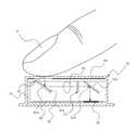
도 1 및 도 2를 참조하면, 일반적인 광 조이스틱(10)은, 광원(11)과 커버(12), 상기 광원에서 출사된 광을 커버(12)로 안내하는 조명 가이드(미도시), 광 신호를 감지하는 이미지 센서(15), 상기 이미지 센서(15)로 광을 안내하는 결상계(14), 및 상기 조명 가이드와 결상계(14)와 상기 광원 등의 부품을 수용하는 홀더(13)를 포함하여 구성된다.1 and 2, a
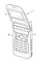
상기 광 조이스틱(10)은 전자기기(1)와 별도로 구비되어 유선 또는 무선으로 연결될 수도 있으나, 근래에는 노트북이나 휴대폰 등과 같은 전자기기의 본체(2)에 직접 탑재되기도 한다.The
광원은 적어도 하나 이상의 적외선 LED로 구성되며, 플렉서블 피시비 (FPCB)(미도시)에 실장되어 홀더 외측의 돌기(미도시)에 끼워지게 된다.The light source consists of at least one infrared LED and is mounted on a flexible PCB (FPCB) (not shown) to fit into a protrusion (not shown) outside the holder.
상기 커버의 외측면(상측면)에는 전자기기의 조작을 위하여 손가락 등의 피사체(P)가 접촉되는 조작면이 형성되며, 상기 이미지 센서(15)는 입력되는 광신호의 처리를 위하여 PCB(미도시)상에 구비된다.The outer surface (upper surface) of the cover is provided with an operation surface to contact the subject (P) such as a finger for the operation of the electronic device, the
이에 따라, 상기 조작면에 피사체(P)인 손가락을 접촉시켜 움직이면, 상기 손가락의 움직임에 따라 상기 이미지 센서(15)에 입력되는 광 신호가 변화되어 상기 손가락의 움직임에 따라 상기 전자기기가 조작될 수 있다.Accordingly, when the finger, which is the subject P, moves on the operation surface, the optical signal input to the
보다 상세하게 설명하면, 상기 커버(12)의 상측면, 보다 상세하게는 조작면에 피사체(P)가 접촉되지 않은 상태에서는 상기 광원(11)에서 출사된 광이 상기 조명 가이드를 거쳐 상기 커버(12)를 투과하면서 상기 커버(12)의 외부로 방출된다.In more detail, in the state where the subject P is not in contact with the upper side of the
반면, 상기 커버(12)의 상측면에 손가락 등의 피사체가 접촉되면, 상기 광원(11)에서 출사된 광이 상기 피사체(P)에 부딪혀 반사된 후 상기 결상계(14)를 거쳐 상기 이미지 센서(15)에서 입사되고, 이에 따라 피사체의 이미지가 광신호로 촬상된다.On the other hand, when a subject such as a finger contacts the upper side of the
여기서 상기 결상계(14)는 유리나 광학 플라스틱과 같은 재질로된 프리즘(14a)과 렌즈(14b) 등 복수개의 구성을 포함하며, 상기 피사체에 반사된 광을 소정방향 반사 및 또는 굴절 시킴과 동시에 집광하여 상기 이미지 센서(15)로 전달하고, 상기 커버(12) 외부의 상기 피사체가 움직이게 되면, 상기 피사체(12)에 반사되어 상기 이미지 센서(15)에 감지되는 광 신호도 변화된다.Here, the
그리고 상기 이미지 센서(15)가 상기 피사체의 움직임에 의한 광 신호의 변 화를 감지하고, 이에 따라 상기 전자기기(1)의 디스플레이부(3)에 커서 또는 포인터의 이동이 표시되었다.The
상기 이미지 센서(15)에 의한 광 신호의 검출 및 이미지의 제어방식은 노트북 컴퓨터에 탑재된 광 마우스에서와 유사하므로 그에 대한 상세한 설명을 생략한다.The optical signal detection and image control scheme by the
상술한 일반적인 광 조이스틱은 피사체의 움직임에 따라 커서, 즉 포인터를 이동시켜 휴대 전자기기를 조작하기 때문에, 종래의 키패드 버튼에 의한 커서의 이동으로 휴대 전자기기를 조작하는 방식에 비해 편리한 조작을 구현할 수는 있다.Since the above-described general optical joystick operates a portable electronic device by moving a cursor, that is, a pointer according to a movement of a subject, it is possible to implement a convenient operation as compared to a method of operating a portable electronic device by moving a cursor by a conventional keypad button. There is.
그러나, 종래 광 조이스틱은 제조되는 과정에서 고가의 부품들이 다수개 실장됨에 따라 제조비용이 상승함은 물론, 제조공정이 복잡하여 생산성이 저하되는 문제점이 있다.However, the conventional optical joystick has a problem in that the manufacturing cost increases as a large number of expensive components are mounted in the manufacturing process, and the manufacturing process is complicated, thereby decreasing productivity.
즉, 종래 광 조이스틱의 경우 커버 내부에 수용되는 홀더 및 홀더 내부에 수용되는 결상계와 이미지센서 등과 같이 비교적 제조단가가 높고 조립성이 떨어지는 다수개의 부품들을 작업순서에 따라 순차적으로 조립하게 되는데, 이렇게 홀더 내부에 수용되는 다수개의 부품들은 조립과정에서 부품의 크기가 너무 작아 작업성이 떨어짐은 물론 조립이 완료되었다 하더라도 불량률이 높아 제품의 생산성이 저하되는 문제점이 있다.That is, in the case of the conventional optical joystick, a plurality of parts having a relatively high manufacturing cost and low assemblability, such as a holder accommodated inside the cover and an imaging system and an image sensor accommodated inside the holder, are sequentially assembled according to a work order. A large number of parts accommodated in the holder has a problem that the size of the parts is too small in the assembly process, the workability is lowered, and even if the assembly is completed, the defect rate is high and the productivity of the product is lowered.
본 발명은 상기와 같은 문제점을 감안하여 안출된 것으로, 조립 부품의 간소화를 통해 제조원가의 절감은 물론, 부품 간소를 통한 조립성의 개선으로 생산성을 크게 향상시킨 초슬림 광조이스틱을 제공하는데 목적이 있다.The present invention has been made in view of the above problems, and an object of the present invention is to provide an ultra-slim optical joystick that greatly improves productivity by reducing assembly cost through simplifying assembly parts and improving assembly performance through simple parts.
본 발명의 다른 목적은, 결상계를 구성하며 빛의 경로를 수평방향과 수직방향으로 굴절시키는 프리즘을 홀더 일체형으로 구성하여 조립부품의 간소화를 통해 생산성을 증대시킬 수 있도록 하는데 있다.Another object of the present invention is to configure the imaging system and to configure the prism for refracting the light path in the horizontal direction and the vertical direction in a single-piece holder to increase the productivity through the simplification of the assembly.
본 발명의 다른 목적은, 적외선LED를 별도의 모듈로 구성하지 않고, 메인기판에 직접 실장함으로써 제조비용 절감은 물론 제조과정 단계를 축소하는데 있다.Another object of the present invention is to reduce the manufacturing cost as well as to reduce the manufacturing process step by directly mounting the infrared LED on the main board without configuring a separate module.
본 발명의 실시예에 따른 초슬림 광조이스틱은 결상계를 구성하는 프리즘을 별도의 사출 성형을 통해 제조하지 않고 홀더와 일체형으로 제조함으로써, 조립 부품의 간소화로 제조원가의 절감은 물론, 부품 간소를 통한 조립성의 개선으로 생산성을 크게 향상시킬 수 있는 효과가 있다.Ultra-slim optical joystick according to an embodiment of the present invention by manufacturing the prism constituting the imaging system integrally with the holder instead of manufacturing through a separate injection molding, as well as the reduction of manufacturing cost by simplifying the assembly parts, assembling through simple parts Improving productivity has the effect of significantly improving productivity.
또한, 본 발명은 적외선LED를 별도의 모듈로 구성하지 않고, 메인기판에 직접 실장함으로써 제조비용 절감은 물론 제조과정 단계를 축소할 수 있는 효과가 있다.In addition, the present invention has the effect of reducing the manufacturing process as well as reducing the manufacturing process step by mounting the infrared LED directly on the main board without configuring a separate module.
이와 같은 목적을 효과적으로 달성하기 위해 본 발명은 메인 기판; 상기 메인 기판에 SMT공정으로 실장되어 적외선을 출사하는 광원; 상기 적외선 광원에 의해 조명되며, 피사체가 접촉되는 하우징; 상기 하우징 내부에 수용되며, 내부에 광원의 빛이 반사되도록 한 쌍의 반사부재가 형성된 홀더; 상기 한 쌍의 반사부재 사이에 구성되어 빛을 결상하는 결상렌즈; 상기 결상렌즈를 통과하여 진행되는 빛중 잡광을 차단하는 마스크; 그리고, 상기 마스크를 통과하여 진행되는 빛을 검출하는 수광부;로 구성됨을 특징으로 한다.In order to effectively achieve the above object, the present invention is a main substrate; A light source mounted on the main substrate by an SMT process to emit infrared light; A housing illuminated by the infrared light source and in contact with a subject; A holder accommodated in the housing and having a pair of reflective members formed therein to reflect light from the light source; An imaging lens formed between the pair of reflecting members to form light; A mask which blocks out of the light that passes through the imaging lens; And a light receiving unit that detects light that passes through the mask.
이하, 본 발명의 바람직한 실시예를 첨부된 도면을 참조하여 상세히 설명하면 다음과 같다.Hereinafter, preferred embodiments of the present invention will be described in detail with reference to the accompanying drawings.
도 3은 본 발명의 실시예에 따른 초슬림 광조이스틱을 보인 분해 사시도이고, 도 4는 본 발명의 실시예에 따른 초슬림 광조이스틱의 단면도이며, 도 5는 본 발명의 실시예에 따른 광조이스틱의 작용상태도이다.3 is an exploded perspective view showing an ultra-slim light joystick according to an embodiment of the present invention, Figure 4 is a cross-sectional view of the ultra-slim light joystick according to an embodiment of the present invention, Figure 5 is the action of the light joystick according to an embodiment of the present invention State diagram.
도시된 바와 같이, 본 발명의 실시예에 따른 광 조이스틱은 광원(20)과 피사체가 접촉되는 하우징(30)과 하우징(30)과 결합되는 홀더(40)와 빛을 결상하는 결상렌즈(50)와 빛의 산란을 차단하는 마스크(55)와 빛을 검출하는 수광부(60)를 포함하여 구성된다.As shown in the drawing, the optical joystick according to the embodiment of the present invention has a
광원(20)은 적외선을 출사하는 적어도 하나의 사이드뷰 타입의 LED가 사용되며, 메인기판(64)에 실장된다.As the
또한 광원(20)은 빛의 세기를 증대시킬 수 있도록 한 쌍이 구비될 수도 있으나, 이러한 경우 설치공간이 확장되기 때문에 도면에는 도시하지 않았지만 LED 내부에 2개의 발광 다이칩을 실장하여 빛의 세기를 증대시킬 수도 있다.In addition, a pair of
하우징(30)은 피사체가 접촉되며 광원(20)의 빛이 투과되는 투과존(32)과 외부광을 차단하는 비투과존(34)으로 구성된다.The
이때, 투과존(32)과 비투과존(34)의 구분은 각각 별도로 제조하여 결합함으로써 구분될 수도 있고, 별도의 차폐 테입(미도시)을 부착하여 구분될 수도 있다.At this time, the separation of the
이와 같은 하우징(30)은 적외선 이외의 빛은 차단하여 투과되지 못하도록 광학 플라스틱으로 제조될 수 있으며, 투명 플라스틱에 적외선만이 통과될 수 있도록 표면에 도료 코팅이 적용될 수도 있다.Such a
한편, 하우징(30) 내부에는 내부에 수용공간이 구비되며, 한 쌍의 반사부재(42)가 일체로 형성된 홀더(40)가 결합된다.On the other hand, the
홀더(40)는 외부광이 투과되지 않는 합성수지재를 사출 성형하여 제조될 수 있다.The
홀더(40) 내부에 형성된 반사부재(42)는 반사플레이트(42a)와 반사플레이트(42a)의 표면에 구성된 반사재(42b)를 포함하여 구비된다.The
반사플레이트(42a)는 홀더(40) 내부에서 동일 경사각을 유지하도록 각각 이격된 채 일체로 형성된다.Reflecting
즉, 반사플레이트(42a)는 광원(20)의 빛이 수직방향에서 수평방향으로 다시 수평방향에서 수직방향으로 반사될 수 있도록 45°의 경사각을 유지하도록 홀더 내부에 구성된다.That is, the reflecting
따라서, 반사플레이트(42a)는 홀더(40)의 내측 양단부에 형성되어 빛의 경로를 변경할 수 있게 된다.Therefore, the reflecting
이와 같은 반사플레이트(42a)는 광원(20)의 빛이 보다 잘 반사된 상태로 진행되기 위해 반사재(42b)가 표면에 구성되어 있다. 이때, 반사재(42b)가 반사 플레이트(42a)의 표면에 구성되어 있지 않게 되면, 광원의 빛이 반사플레이트(42a)에 모두 흡수되어 빛의 경로를 변경할 수 없기 때문에 반드시 반사플레이트(42a)의 표면에 도포 또는 증착되어야만 한다.In the
반사재(42b)는 반사율이 높은 금속재 예를 들어 알루미늄(Al) 또는 은(Ag) 등이 소재로서 사용될 수 있는데, 반드시 금속재가 사용되는 것은 아니며 비금속재 중에서 반사율이 높은 소재가 선택된다면 금속재 대신 사용도 가능하다.The
여기서, 반사재(42b)가 반사플레이트(42a)에 구성될 때에는 코팅과 같은 작업공정이 진행될 수 있으며, 작업자가 직접 반사플레이트(42a)의 표면에 반사 재(42b)를 밀착 구성시킬 수도 있다.Here, when the reflecting
그리고, 홀더의 외부에는 LED로부터 조사된 빛을 하우징으로 안내하는 가이드면이 포함된다. 이때, 가이드면은 조사된 빛의 유실을 최소화하기 위함이다.And, the outer surface of the holder includes a guide surface for guiding light emitted from the LED to the housing. At this time, the guide surface is to minimize the loss of the irradiated light.
또한 홀더(40)의 내부에는 한 쌍으로 이루어진 반사플레이트(42a)의 사이에 결상렌즈(50)가 배치된다.In addition, an
결상렌즈(50)는 볼록렌즈로서 반사부재(42b)를 통해 반사되는 빛이 집광된 상태로 진행되기 위해 구비된다.The
그리고, 한 쌍의 반사플레이트 사이에는 마스크(55)가 배치된다. 마스크(55)는 결상렌즈(50)를 통과하여 진행되는 빛중 잡광을 차단하게 되는데, 이는 후술할 수광부(60)에서 피사체의 이동에 따른 인식률을 높이기 위함이다.The
이때, 마스크(55)는 홀더에 형성된 걸림홈(59)에 끼워지는 걸림바(56)와 걸림바에서 일체로 연장되어 잡광을 차단하는 잡광차단면(57)으로 구성되며, 잡광차단면(57)에 천공되어 수광부(60)로 유입되는 빛의 양을 조절하는 홀(58)을 포함한다.At this time, the
여기서, 마스크는 불투명의 필름재로 구성되는데, PP(폴리프로필렌),PET(폴리에틸렌),PC(폴리카보네이트) 중 어느 하나로 형성될 수 있다.Here, the mask is composed of an opaque film material, it may be formed of any one of PP (polypropylene), PET (polyethylene), PC (polycarbonate).
그리고 마스크(55)를 통과하여 진행되는 빛을 검출하는 수광부(60)가 구성된다.And the
수광부(60)는 광원(20)의 빛을 센싱영역(62)을 통해 연속적으로 촬상하고, 촬상된 영상화면을 비교하여 변화된 영상화면 만큼 변위값으로 연산하게 된다. 여 기서, 수광부(60)는 CSP(Chip Scale Package)이미지센서로 구성되어 메인기판(64)에 SMT공정으로 실장된다.The
그리고, 본 발명에서는 메인기판(64)을 기준으로 광원(20)의 반대편에 돔스위치(미도시)가 포함되어 구성될 수 있다.In the present invention, the dome switch (not shown) may be included on the opposite side of the
이하에서는 본 발명의 실시예에 따른 초슬림 광조이스틱의 작용 상태를 설명하겠다.Hereinafter will be described the operation state of the ultra-slim optical joystick according to an embodiment of the present invention.
광원(20)의 빛이 하우징의 투과존(32)으로 방사되기 시작하고 피사체가 하우징의 투과존(32)에 접촉되어 있게 되면, 빛은 투과존(32)을 통과하여 피사체에 부딪힌 후 반사되어 하우징(30) 내부로 유입된다.When the light of the
하우징(30)으로 유입된 빛은 하우징(30)과 일체로 형성된 반사부재(42)를 통해 수직방향에서 수평방향으로 반사된다. Light introduced into the
빛이 반사되어 진행하는 과정에서는 결상렌즈(50)가 분산된 빛을 집광하게 된다.In the process of reflecting light, the
이렇게 결상렌즈(50)를 통과한 빛을 마스크(55)에 의해 잡광이 차단되고, 마스크(55)를 통과한 빛은 반사부재(42)를 통해 다시 수직방향으로 반사되면서 수광부(60)로 전달된다.The light passing through the
수광부(60)는 유입된 빛을 연속적으로 촬상하고, 수광되는 빛의 변화에 따라 변위값으로 연산하여 휴대 단말기의 마이컴으로 전송하게 된다.The
따라서, 본 발명은 적외선LED를 별도의 모듈로 구성하지 않고, 메인기판에 직접 실장하며, 빛의 양을 조절하는 마스크를 필름소재를 사용하여 제조비용 절감 은 물론 제조과정 단계를 축소할 수 있다.Therefore, the present invention can be mounted directly on the main substrate without configuring the infrared LED as a separate module, and the manufacturing cost can be reduced as well as the manufacturing process step by using a film material to control the amount of light.
이상에서 본 발명의 실시예에 따른 초슬림 광조이스틱에 대해 설명하였으나 본 발명은 이에 한정하지 아니하며 당업자라면 그 응용과 변형이 가능함은 물론이다.Although the ultra-slim optical joystick according to the embodiment of the present invention has been described above, the present invention is not limited thereto, and those skilled in the art can apply and modify the same.
도 1은 휴대 단말기에 광 조이스틱이 설치된 상태를 보인 사시도.1 is a perspective view showing a state in which an optical joystick is installed in a portable terminal.
도 2는 종래 광 조이스틱이 작동되는 과정을 보인 작용 상태도.Figure 2 is a state diagram showing the operation of the conventional optical joystick operation.
도 3은 본 발명의 실시예에 따른 초 슬림 광 조이스틱을 보인 분해 사시도.Figure 3 is an exploded perspective view showing an ultra slim optical joystick according to an embodiment of the present invention.
도 4는 본 발명의 실시예에 따른 광 조이스틱의 단면도.4 is a cross-sectional view of an optical joystick according to an embodiment of the present invention.
도 5는 본 발명의 실시예에 따른 광 조이스틱의 작용상태도.5 is a working state of the optical joystick according to an embodiment of the present invention.
*도면 각 주요 부분에 대한 부호의 설명** Explanation of symbols for each major part of drawing *
20: 광원30: 하우징20: light source 30: housing
32: 투과존34: 비투과존32: transmission zone 34: non-transmission zone
40: 홀더42: 반사부재40: holder 42: reflective member
42a: 반사플레이트42b: 반사재42a: reflecting
50: 결상렌즈 55: 마스크50: imaging lens 55: mask
56: 걸림바 57: 잡광차단면56: jam bar 57: light blocking surface
58: 홀 60: 수광부58: hall 60: light receiver
59: 걸림홈 62: 센싱영역59: locking groove 62: sensing area
64: 메인기판64: main board
Claims (7)
Translated fromKoreanPriority Applications (5)
| Application Number | Priority Date | Filing Date | Title |
|---|---|---|---|
| KR1020090025131AKR101092857B1 (en) | 2009-03-24 | 2009-03-24 | Ultra Slim Light Joystick |
| EP09170618AEP2214081A1 (en) | 2009-01-30 | 2009-09-17 | Optical pointing device and portable electronic device having the same |
| JP2009217015AJP2010176656A (en) | 2009-01-30 | 2009-09-18 | Optical pointing device and portable electronic device having the same |
| US12/566,411US20100194712A1 (en) | 2009-01-30 | 2009-09-24 | Optical pointing device and portable electronic device having the same |
| CN200910177369ACN101794183A (en) | 2009-01-30 | 2009-10-09 | Optical pointing device and portable electronic device having the same |
Applications Claiming Priority (1)
| Application Number | Priority Date | Filing Date | Title |
|---|---|---|---|
| KR1020090025131AKR101092857B1 (en) | 2009-03-24 | 2009-03-24 | Ultra Slim Light Joystick |
Publications (2)
| Publication Number | Publication Date |
|---|---|
| KR20100106873A KR20100106873A (en) | 2010-10-04 |
| KR101092857B1true KR101092857B1 (en) | 2011-12-15 |
Family
ID=43128887
Family Applications (1)
| Application Number | Title | Priority Date | Filing Date |
|---|---|---|---|
| KR1020090025131AExpired - Fee RelatedKR101092857B1 (en) | 2009-01-30 | 2009-03-24 | Ultra Slim Light Joystick |
Country Status (1)
| Country | Link |
|---|---|
| KR (1) | KR101092857B1 (en) |
Citations (3)
| Publication number | Priority date | Publication date | Assignee | Title |
|---|---|---|---|---|
| KR100636412B1 (en) | 2004-08-20 | 2006-10-19 | 크루셜텍(주) | Ultra thin optical joystick and personal portable device having an ultra thin optical joystick |
| JP2008226224A (en) | 2007-03-08 | 2008-09-25 | Crucialtec Co Ltd | Optical pointing device for mobile terminal device |
| KR100870504B1 (en) | 2007-01-19 | 2008-11-25 | 주식회사 소림 | Optical pointing device for personal handheld device |
- 2009
- 2009-03-24KRKR1020090025131Apatent/KR101092857B1/ennot_activeExpired - Fee Related
Patent Citations (3)
| Publication number | Priority date | Publication date | Assignee | Title |
|---|---|---|---|---|
| KR100636412B1 (en) | 2004-08-20 | 2006-10-19 | 크루셜텍(주) | Ultra thin optical joystick and personal portable device having an ultra thin optical joystick |
| KR100870504B1 (en) | 2007-01-19 | 2008-11-25 | 주식회사 소림 | Optical pointing device for personal handheld device |
| JP2008226224A (en) | 2007-03-08 | 2008-09-25 | Crucialtec Co Ltd | Optical pointing device for mobile terminal device |
Also Published As
| Publication number | Publication date |
|---|---|
| KR20100106873A (en) | 2010-10-04 |
Similar Documents
| Publication | Publication Date | Title |
|---|---|---|
| US20090184852A1 (en) | Optical joystick and portable electronic device having the same | |
| JP4243306B2 (en) | Personal portable terminal including ultra-thin optical joystick and ultra-thin optical joystick | |
| KR101232596B1 (en) | Pointing device of laminating structure and portable terminal using the same | |
| EP2214081A1 (en) | Optical pointing device and portable electronic device having the same | |
| KR100636412B1 (en) | Ultra thin optical joystick and personal portable device having an ultra thin optical joystick | |
| KR101092857B1 (en) | Ultra Slim Light Joystick | |
| KR101388697B1 (en) | Lens and Optical Navigation Module having the same | |
| KR101044145B1 (en) | Optical pointing device | |
| KR101167061B1 (en) | Optical joystick and mobile device having it | |
| KR101089065B1 (en) | Ultra slim optical joystick | |
| KR101021072B1 (en) | Optical joysticks and portable electronic devices having the same | |
| KR101151230B1 (en) | Ultra slim optical joystick and mobile terminal having it | |
| KR101092855B1 (en) | Optical joystick and portable terminal having same | |
| KR20100138093A (en) | Ultra slim optical joystick and mobile terminal having same | |
| KR20100127956A (en) | Ultra slim optical joystick | |
| KR100787616B1 (en) | Ultra slim optical pointing device key-module and small portable device using the same | |
| KR101174441B1 (en) | Optical input device using side directional light source | |
| KR101349257B1 (en) | Motion sensing switch | |
| KR20110075866A (en) | Ultra slim optical joystick and mobile terminal having same | |
| KR101111900B1 (en) | Input device and portable terminal using same | |
| KR101337972B1 (en) | Motion sensing switch | |
| KR20110134775A (en) | Optical input | |
| KR20110040279A (en) | Optical joystick and portable terminal having same | |
| KR20100035968A (en) | Optical pointing device and portable terminal having the same | |
| KR20110081566A (en) | Optical joystick module and portable terminal having same |
Legal Events
| Date | Code | Title | Description |
|---|---|---|---|
| PA0109 | Patent application | St.27 status event code:A-0-1-A10-A12-nap-PA0109 | |
| P11-X000 | Amendment of application requested | St.27 status event code:A-2-2-P10-P11-nap-X000 | |
| P13-X000 | Application amended | St.27 status event code:A-2-2-P10-P13-nap-X000 | |
| P11-X000 | Amendment of application requested | St.27 status event code:A-2-2-P10-P11-nap-X000 | |
| P13-X000 | Application amended | St.27 status event code:A-2-2-P10-P13-nap-X000 | |
| P11-X000 | Amendment of application requested | St.27 status event code:A-2-2-P10-P11-nap-X000 | |
| P13-X000 | Application amended | St.27 status event code:A-2-2-P10-P13-nap-X000 | |
| R18-X000 | Changes to party contact information recorded | St.27 status event code:A-3-3-R10-R18-oth-X000 | |
| A201 | Request for examination | ||
| PA0201 | Request for examination | St.27 status event code:A-1-2-D10-D11-exm-PA0201 | |
| PG1501 | Laying open of application | St.27 status event code:A-1-1-Q10-Q12-nap-PG1501 | |
| PN2301 | Change of applicant | St.27 status event code:A-3-3-R10-R13-asn-PN2301 St.27 status event code:A-3-3-R10-R11-asn-PN2301 | |
| E902 | Notification of reason for refusal | ||
| PE0902 | Notice of grounds for rejection | St.27 status event code:A-1-2-D10-D21-exm-PE0902 | |
| P11-X000 | Amendment of application requested | St.27 status event code:A-2-2-P10-P11-nap-X000 | |
| P13-X000 | Application amended | St.27 status event code:A-2-2-P10-P13-nap-X000 | |
| E701 | Decision to grant or registration of patent right | ||
| PE0701 | Decision of registration | St.27 status event code:A-1-2-D10-D22-exm-PE0701 | |
| PN2301 | Change of applicant | St.27 status event code:A-3-3-R10-R13-asn-PN2301 St.27 status event code:A-3-3-R10-R11-asn-PN2301 | |
| GRNT | Written decision to grant | ||
| PR0701 | Registration of establishment | St.27 status event code:A-2-4-F10-F11-exm-PR0701 | |
| PR1002 | Payment of registration fee | St.27 status event code:A-2-2-U10-U11-oth-PR1002 Fee payment year number:1 | |
| PG1601 | Publication of registration | St.27 status event code:A-4-4-Q10-Q13-nap-PG1601 | |
| P22-X000 | Classification modified | St.27 status event code:A-4-4-P10-P22-nap-X000 | |
| R18-X000 | Changes to party contact information recorded | St.27 status event code:A-5-5-R10-R18-oth-X000 | |
| FPAY | Annual fee payment | Payment date:20141127 Year of fee payment:4 | |
| PR1001 | Payment of annual fee | St.27 status event code:A-4-4-U10-U11-oth-PR1001 Fee payment year number:4 | |
| R18-X000 | Changes to party contact information recorded | St.27 status event code:A-5-5-R10-R18-oth-X000 | |
| R18-X000 | Changes to party contact information recorded | St.27 status event code:A-5-5-R10-R18-oth-X000 | |
| R18-X000 | Changes to party contact information recorded | St.27 status event code:A-5-5-R10-R18-oth-X000 | |
| FPAY | Annual fee payment | Payment date:20150909 Year of fee payment:5 | |
| PR1001 | Payment of annual fee | St.27 status event code:A-4-4-U10-U11-oth-PR1001 Fee payment year number:5 | |
| R18-X000 | Changes to party contact information recorded | St.27 status event code:A-5-5-R10-R18-oth-X000 | |
| FPAY | Annual fee payment | Payment date:20160906 Year of fee payment:6 | |
| PR1001 | Payment of annual fee | St.27 status event code:A-4-4-U10-U11-oth-PR1001 Fee payment year number:6 | |
| L13-X000 | Limitation or reissue of ip right requested | St.27 status event code:A-2-3-L10-L13-lim-X000 | |
| U15-X000 | Partial renewal or maintenance fee paid modifying the ip right scope | St.27 status event code:A-4-4-U10-U15-oth-X000 | |
| FPAY | Annual fee payment | Payment date:20170907 Year of fee payment:7 | |
| PR1001 | Payment of annual fee | St.27 status event code:A-4-4-U10-U11-oth-PR1001 Fee payment year number:7 | |
| PN2301 | Change of applicant | St.27 status event code:A-5-5-R10-R13-asn-PN2301 St.27 status event code:A-5-5-R10-R11-asn-PN2301 | |
| PR1001 | Payment of annual fee | St.27 status event code:A-4-4-U10-U11-oth-PR1001 Fee payment year number:8 | |
| PN2301 | Change of applicant | St.27 status event code:A-5-5-R10-R11-asn-PN2301 | |
| PN2301 | Change of applicant | St.27 status event code:A-5-5-R10-R14-asn-PN2301 | |
| FPAY | Annual fee payment | Payment date:20190909 Year of fee payment:9 | |
| PR1001 | Payment of annual fee | St.27 status event code:A-4-4-U10-U11-oth-PR1001 Fee payment year number:9 | |
| PC1903 | Unpaid annual fee | St.27 status event code:A-4-4-U10-U13-oth-PC1903 Not in force date:20201207 Payment event data comment text:Termination Category : DEFAULT_OF_REGISTRATION_FEE | |
| R18-X000 | Changes to party contact information recorded | St.27 status event code:A-5-5-R10-R18-oth-X000 | |
| PC1903 | Unpaid annual fee | St.27 status event code:N-4-6-H10-H13-oth-PC1903 Ip right cessation event data comment text:Termination Category : DEFAULT_OF_REGISTRATION_FEE Not in force date:20201207 | |
| R18-X000 | Changes to party contact information recorded | St.27 status event code:A-5-5-R10-R18-oth-X000 | |
| R18-X000 | Changes to party contact information recorded | St.27 status event code:A-5-5-R10-R18-oth-X000 | |
| R18-X000 | Changes to party contact information recorded | St.27 status event code:A-5-5-R10-R18-oth-X000 |