KR101091696B1 - Ubiquitous sensor network system and method of configuring the same - Google Patents
Ubiquitous sensor network system and method of configuring the sameDownload PDFInfo
- Publication number
- KR101091696B1 KR101091696B1KR1020097016499AKR20097016499AKR101091696B1KR 101091696 B1KR101091696 B1KR 101091696B1KR 1020097016499 AKR1020097016499 AKR 1020097016499AKR 20097016499 AKR20097016499 AKR 20097016499AKR 101091696 B1KR101091696 B1KR 101091696B1
- Authority
- KR
- South Korea
- Prior art keywords
- sensor
- sensor network
- network
- server
- sensor node
- Prior art date
- Legal status (The legal status is an assumption and is not a legal conclusion. Google has not performed a legal analysis and makes no representation as to the accuracy of the status listed.)
- Expired - Fee Related
Links
Images


Classifications
- H—ELECTRICITY
- H04—ELECTRIC COMMUNICATION TECHNIQUE
- H04L—TRANSMISSION OF DIGITAL INFORMATION, e.g. TELEGRAPHIC COMMUNICATION
- H04L12/00—Data switching networks
- H04L12/28—Data switching networks characterised by path configuration, e.g. LAN [Local Area Networks] or WAN [Wide Area Networks]
- H—ELECTRICITY
- H04—ELECTRIC COMMUNICATION TECHNIQUE
- H04L—TRANSMISSION OF DIGITAL INFORMATION, e.g. TELEGRAPHIC COMMUNICATION
- H04L12/00—Data switching networks
- H04L12/28—Data switching networks characterised by path configuration, e.g. LAN [Local Area Networks] or WAN [Wide Area Networks]
- H04L12/2803—Home automation networks
- H04L12/2807—Exchanging configuration information on appliance services in a home automation network
- H04L12/2809—Exchanging configuration information on appliance services in a home automation network indicating that an appliance service is present in a home automation network
- H—ELECTRICITY
- H04—ELECTRIC COMMUNICATION TECHNIQUE
- H04L—TRANSMISSION OF DIGITAL INFORMATION, e.g. TELEGRAPHIC COMMUNICATION
- H04L41/00—Arrangements for maintenance, administration or management of data switching networks, e.g. of packet switching networks
- H04L41/08—Configuration management of networks or network elements
- H04L41/0803—Configuration setting
- H04L41/0813—Configuration setting characterised by the conditions triggering a change of settings
- H—ELECTRICITY
- H04—ELECTRIC COMMUNICATION TECHNIQUE
- H04W—WIRELESS COMMUNICATION NETWORKS
- H04W84/00—Network topologies
- H04W84/18—Self-organising networks, e.g. ad-hoc networks or sensor networks
- H—ELECTRICITY
- H04—ELECTRIC COMMUNICATION TECHNIQUE
- H04L—TRANSMISSION OF DIGITAL INFORMATION, e.g. TELEGRAPHIC COMMUNICATION
- H04L12/00—Data switching networks
- H04L12/28—Data switching networks characterised by path configuration, e.g. LAN [Local Area Networks] or WAN [Wide Area Networks]
- H04L12/2803—Home automation networks
- H04L2012/284—Home automation networks characterised by the type of medium used
- H04L2012/2841—Wireless
- H—ELECTRICITY
- H04—ELECTRIC COMMUNICATION TECHNIQUE
- H04L—TRANSMISSION OF DIGITAL INFORMATION, e.g. TELEGRAPHIC COMMUNICATION
- H04L41/00—Arrangements for maintenance, administration or management of data switching networks, e.g. of packet switching networks
- H04L41/12—Discovery or management of network topologies
- H—ELECTRICITY
- H04—ELECTRIC COMMUNICATION TECHNIQUE
- H04L—TRANSMISSION OF DIGITAL INFORMATION, e.g. TELEGRAPHIC COMMUNICATION
- H04L67/00—Network arrangements or protocols for supporting network services or applications
- H04L67/01—Protocols
- H04L67/12—Protocols specially adapted for proprietary or special-purpose networking environments, e.g. medical networks, sensor networks, networks in vehicles or remote metering networks
- H—ELECTRICITY
- H04—ELECTRIC COMMUNICATION TECHNIQUE
- H04W—WIRELESS COMMUNICATION NETWORKS
- H04W40/00—Communication routing or communication path finding
Landscapes
- Engineering & Computer Science (AREA)
- Computer Networks & Wireless Communication (AREA)
- Signal Processing (AREA)
- Automation & Control Theory (AREA)
- Data Exchanges In Wide-Area Networks (AREA)
Abstract
Translated fromKoreanDescription
Translated fromKorean본 발명의 실시예들은 센서 네트워크에 관한 것으로 특히, 유비쿼터스 네트워크 시스템 및 이를 구성하는 방법에 관한 것이다.Embodiments of the present invention relate to sensor networks, and more particularly, to a ubiquitous network system and a method of configuring the same.
유비쿼터스 센서 네트워크(Ubiquitous Sensor Network)란 일반적으로 각종 센서 노드와 같은 작은 장치들이 정보를 무선으로 수신할 수 있도록 구성된 네트워크를 의미한다. 예를 들어, 센서 네트워크의 노드는 온도 센서, 방범 센서, 지문 인식 센서 등의 센서 및 알람, 창문 여닫이 장치, 전등 제어 등의 제어 장치 그리고 사진, 동영상 전송 카메라와 같은 데이터 전송 장치를 포함할 수 있다.The ubiquitous sensor network generally refers to a network configured such that small devices such as various sensor nodes can wirelessly receive information. For example, the nodes of the sensor network may include sensors such as temperature sensors, security sensors, fingerprint sensors, and control devices such as alarms, window cases, light controls, and data transmission devices such as photographic and video transmission cameras. .
유비쿼터스 센서 네트워크를 정상적으로 동작시키기 위해서는 사용자(관리자)는 유비쿼터스 센서 네트워크에 포함된 노드들(예를 들어, 센서 노드들, 서버 등)을 설정해야 한다. 예를 들어, 만일 노드가 온도 센서 노드에 상응하는 경우라면 사용자(관리자)는 최소 또는 최대 임계치를 설정하거나, 온도 센서 노드가 온도 정보를 보내야 하는 네트워크 경로 및/또는 서버에 관한 정보를 설정할 수 있다.In order to operate a ubiquitous sensor network normally, a user (administrator) needs to configure nodes (eg, sensor nodes, servers, etc.) included in the ubiquitous sensor network. For example, if the node corresponds to a temperature sensor node, the user (administrator) can set a minimum or maximum threshold, or set up information about the network path and / or server to which the temperature sensor node should send temperature information. .
다만 사용자(관리자)는 수동으로 터미널을 이용하여 각 노드들을 연결하여 각 노드들의 기능에 적절한 구성을 설정하는 경우에는 많은 시간이 요구된다.However, when a user (administrator) manually connects each node using a terminal and sets an appropriate configuration for each node's function, a lot of time is required.
기술적 과제Technical Challenge
본 발명의 목적은 상기 종래 기술의 문제점을 해결하기 위하여 센서 네트워크 구성 정보를 포함하는 착탈 가능한 메모리 장치를 이용하여 자동으로 구성될 수 있는 유비쿼터스 네트워크 시스템을 제공하는데 있다.An object of the present invention is to provide a ubiquitous network system that can be automatically configured using a removable memory device including the sensor network configuration information in order to solve the problems of the prior art.
본 발명의 다른 목적은 상기 유비쿼터스 네트워크 시스템을 구성할 수 있는 방법을 제공하는 데 있다.Another object of the present invention is to provide a method for configuring the ubiquitous network system.
기술적 해결방법Technical solution
상기 목적을 달성하기 위하여 착탈 가능한 메모리 장치와 연결 가능한 라우터 및 센서 노드를 포함하는 유비쿼터스 센서 네트워크(USN, Ubiquitous Sensor Network) 시스템에 있어서, 본 발명의 유비쿼터스 센서 네트워크 시스템을 구성하는 방법은 (a) 상기 라우터의 제어 하에, 상기 착탈 가능한 메모리 장치로부터 센서 네트워크 아이디를 포함하는 센서 네트워크 구성 정보를 입력받는 단계, (b) 상기 센서 노드의 제어 하에, 상기 착탈 가능한 메모리 장치로부터 상기 센서 네트워크 아이디를 포함하는 상기 센서 네트워크 구성 정보를 입력받는 단계 및 (c) 상기 라우터 및/또는 상기 센서 노드의 제어 하에, 상기 센서 네트워크 아이디를 기초로 센서 네트워크를 구성하는 단계를 포함한다. 예를 들어, 상기 센서 네트워크 아이디는 상기 착탈 가능한 메모리 장치의 고유 시리얼 넘버에 상응할 수 있다.In order to achieve the above object, in a ubiquitous sensor network (USN) system including a router and a sensor node connectable to a detachable memory device, a method of configuring a ubiquitous sensor network system of the present invention is (a) the Receiving sensor network configuration information including a sensor network ID from the removable memory device under the control of a router; (b) under the control of the sensor node, the sensor network ID from the removable memory device; Receiving sensor network configuration information and (c) configuring a sensor network based on the sensor network ID under the control of the router and / or the sensor node. For example, the sensor network ID may correspond to a unique serial number of the removable memory device.
상기 (a) 단계는 상기 센서 노드가 연결 가능한 서버에 관한 정보를 나타내는 서버 정보 목록을 더 포함하는 상기 센서 네트워크 구성 정보를 입력받는 단계 및 상기 서버 정보 목록을 기초로 상기 센서 노드와 상기 센서 노드와 통신하는 서버 간의 네트워크를 의미하는 서버 네트워크를 구성하는 단계를 포함할 수 있다.The step (a) is a step of receiving the sensor network configuration information further comprising a server information list indicating information on a server that can be connected to the sensor node and the sensor node and the sensor node based on the server information list; It may comprise the step of configuring a server network means a network between the communicating server.
상기 (a) 단계는 상기 센서 네트워크를 구성하는 센서 노드에 관한 정보를 나타내는 센서 노드 정보 목록을 더 포함하는 상기 센서 네트워크 구성 정보를 입력받는 단계를 더 포함할 수 있고, 상기 (c) 단계는 상기 센서 노드의 제어 하에, 상기 센서 네트워크 아이디를 기초로 상기 라우터를 연결하는 단계 및 상기 라우터의 제어 하에, 상기 센서 노드 정보 목록을 기초로 상기 센서 네트워크를 재구성하는 단계를 포함할 수 있다.The step (a) may further comprise the step of receiving the sensor network configuration information further comprising a sensor node information list indicating information on the sensor node constituting the sensor network, the step (c) is Connecting the router based on the sensor network ID under the control of a sensor node, and reconfiguring the sensor network based on the sensor node information list under the control of the router.
상기 (b) 단계는 상기 센서 노드가 연결 가능한 서버에 관한 정보를 나타내는 서버 정보 목록을 더 포함하는 상기 센서 네트워크 구성 정보를 입력받는 단계 및 상기 서버 정보 목록을 기초로 상기 센서 노드와 상기 센서 노드와 통신하는 서버 간의 네트워크를 의미하는 서버 네트워크를 구성하는 단계를 포함할 수 있다.(B) receiving the sensor network configuration information further including a server information list indicating information on a server to which the sensor node is connectable, and the sensor node and the sensor node based on the server information list. It may comprise the step of configuring a server network means a network between the communicating server.
상기 (a) 단계는 상기 센서 네트워크를 구성하는 센서 노드에 관한 정보를 나타내는 센서 노드 정보 목록을 더 포함하는 상기 센서 네트워크 구성 정보를 입력받는 단계를 포함할 수 있고, 상기 (c) 단계는 상기 센서 노드의 제어 하에, 상기 센서 네트워크 아이디를 기초로 상기 라우터를 연결하는 단계 및 상기 라우터의 제어 하에, 상기 센서 노드 정보 목록을 기초로 센서 네트워크를 재구성하는 단계를 포함할 수 있다.The step (a) may include receiving the sensor network configuration information further including a sensor node information list indicating information on the sensor node constituting the sensor network, and the step (c) may include the sensor Connecting the router based on the sensor network ID under the control of a node, and reconfiguring the sensor network based on the sensor node information list under the control of the router.
상기 (a) 단계는 상기 센서 네트워크를 구성하는 센서 노드에 관한 정보를 나타내는 센서 노드 정보 목록을 더 포함하는 상기 센서 네트워크 구성 정보를 입력받는 단계를 포함할 수 있고, 상기 (c) 단계는 상기 센서 노드의 제어 하에, 상기 센서 네트워크 아이디를 기초로 상기 라우터를 연결하는 단계 및 상기 라우터의 제어 하에, 상기 센서 노드 정보 목록을 기초로 센서 네트워크를 재구성하는 단계를 포함할 수 있다.The step (a) may include receiving the sensor network configuration information further including a sensor node information list indicating information on the sensor node constituting the sensor network, and the step (c) may include the sensor Connecting the router based on the sensor network ID under the control of a node, and reconfiguring the sensor network based on the sensor node information list under the control of the router.
상기 방법은 (d) 상기 유비쿼터스 센서 네트워크 시스템에 연결된 서버의 제어 하에, 상기 유비쿼터스 네트워크 시스템을 커스터마이징(customizing)하는 단계를 더 포함할 수 있다.The method may further comprise (d) customizing the ubiquitous network system under the control of a server connected to the ubiquitous sensor network system.
상기 목적을 달성하기 위하여 본 발명의 유비쿼터스 센서 네트워크(USN, Ubiquitous Sensor Network) 시스템은 착탈 가능한 메모리 장치와 연결 가능하고, 상기 착탈 가능한 메모리 장치로부터 센서 네트워크 아이디를 포함하는 센서 네트워크 구성 정보를 입력받는 적어도 하나 이상의 센서 노드 및 상기 착탈 가능한 메모리 장치와 연결 가능하고, 상기 착탈 가능한 메모리 장치로부터 센서 네트워크 아이디를 포함하는 센서 네트워크 구성 정보를 입력받는 라우터를 포함하고, 상기 센서 노드 및 상기 라우터는 상기 센서 네트워크 아이디를 기초로 센서 네트워크를 구성한다. 예를 들어, 상기 센서 네트워크 아이디는 상기 착탈 가능한 메모리 장치의 고유 시리얼 넘버에 상응할 수 있다.In order to achieve the above object, the ubiquitous sensor network (USN) system of the present invention can be connected to a removable memory device, and receives at least sensor network configuration information including a sensor network ID from the removable memory device. A router connectable to at least one sensor node and the removable memory device, the router receiving sensor network configuration information including a sensor network ID from the removable memory device, wherein the sensor node and the router are the sensor network IDs; Configure the sensor network on the basis of For example, the sensor network ID may correspond to a unique serial number of the removable memory device.
상기 시스템은 서버를 더 포함하고, 상기 센서 네트워크 구성 정보는 상기 센서 노드가 연결 가능한 서버에 관한 정보를 나타내는 서버 정보 목록을 더 포함하며, 상기 라우터 및/또는 상기 센서 노드는 상기 서버 정보 목록을 기초로 상기 센서 노드와 상기 서버 간의 네트워크를 의미하는 서버 네트워크를 구성할 수 있다. 예를 들어, 상기 서버는 상기 유비쿼터스 센서 네트워크 시스템을 커스터마이징(customizing)할 수 있다.The system further includes a server, wherein the sensor network configuration information further comprises a server information list indicating information about a server to which the sensor node is connectable, wherein the router and / or the sensor node is based on the server information list. In this case, a server network means a network between the sensor node and the server. For example, the server may customize the ubiquitous sensor network system.
상기 센서 네트워크 구성 정보는 상기 센서 네트워크를 구성하는 센서 노드에 관한 정보를 나타내는 센서 노드 정보 목록을 더 포함할 수 있고, 상기 센서 노드가 상기 센서 네트워크 아이디를 기초로 상기 라우터를 연결하는 경우, 상기 라우터는 상기 센서 노드 정보 목록을 기초로 상기 센서 네트워크를 재구성할 수 있다.The sensor network configuration information may further include a sensor node information list indicating information on sensor nodes constituting the sensor network. When the sensor node connects the router based on the sensor network ID, the router May reconfigure the sensor network based on the sensor node information list.
상기에서 제시한 본 발명의 실시예들은 다음의 장점들을 포함하는 효과를 가질 수 있다. 다만, 본 발명의 모든 실시예들이 이를 전부 포함하여야 한다는 의미는 아니므로, 본 발명의 권리범위는 이에 의하여 제한되는 것으로 이해되어서는 아니 될 것이다.Embodiments of the present invention presented above may have an effect including the following advantages. However, all the embodiments of the present invention are not meant to include them all, and thus the scope of the present invention should not be understood as being limited thereto.
따라서 본 발명의 일 실시예는 센서 네트워크 구성 정보를 포함하는 착탈 가능한 메모리 장치를 이용하여 자동으로 유비쿼터스 네트워크 시스템을 구성할 수 있다.Accordingly, an embodiment of the present invention can automatically configure a ubiquitous network system using a detachable memory device including sensor network configuration information.
또한, 본 발명의 일 실시예는 센서 네트워크 구성 정보에 포함된 서버 정보 목록 및/또는 센서 노드 정보 목록을 이용하여 유비쿼터스 네트워크 시스템을 재구성할 수 있다.In addition, an embodiment of the present invention may reconfigure a ubiquitous network system using a server information list and / or a sensor node information list included in sensor network configuration information.
유리한 효과Favorable effect
본 발명의 실시예들은 다음의 장점들을 포함하는 효과를 가질 수 있다. 다만, 본 발명의 모든 실시예들이 이를 전부 포함하여야 한다는 의미는 아니므로, 본 발명의 권리범위는 이에 의하여 제한되는 것으로 이해되어서는 아니 될 것이다.Embodiments of the present invention may have the effect of including the following advantages. However, all the embodiments of the present invention are not meant to include them all, and thus the scope of the present invention should not be understood as being limited thereto.
본 발명의 일 실시예는 센서 네트워크 구성 정보를 포함하는 착탈 가능한 메모리 장치를 이용하여 자동으로 유비쿼터스 네트워크 시스템을 구성할 수 있다.An embodiment of the present invention can automatically configure a ubiquitous network system using a removable memory device including sensor network configuration information.
또한, 본 발명의 일 실시예는 센서 네트워크 구성 정보에 포함된 서버 정보 목록 및/또는 센서 노드 정보 목록을 이용하여 유비쿼터스 네트워크 시스템을 재구성할 수 있다.In addition, an embodiment of the present invention may reconfigure the ubiquitous network system by using the server information list and / or the sensor node information list included in the sensor network configuration information.
도 1은 본 발명에 일 실시예에 따른 유비쿼터스 네트워크 시스템을 나타내는 도면이다.1 is a diagram illustrating a ubiquitous network system according to an embodiment of the present invention.
도 2는 본 발명의 제1 실시예에 따른 유비쿼터스 네트워크 시스템을 구성하는 방법을 나타내는 흐름도이다.2 is a flowchart illustrating a method of configuring a ubiquitous network system according to a first embodiment of the present invention.
도 3은 본 발명의 제2 실시예에 따른 유비쿼터스 네트워크 시스템을 구성하는 방법을 나타내는 흐름도이다.3 is a flowchart illustrating a method of configuring a ubiquitous network system according to a second embodiment of the present invention.
도 4는 본 발명의 제3 실시예에 따른 유비쿼터스 네트워크 시스템을 구성하는 방법을 나타내는 흐름도이다.4 is a flowchart illustrating a method of configuring a ubiquitous network system according to a third embodiment of the present invention.
도 5는 본 발명의 제4 실시예에 따른 유비쿼터스 네트워크 시스템을 구성하는 방법을 나타내는 흐름도이다.5 is a flowchart illustrating a method of configuring a ubiquitous network system according to a fourth embodiment of the present invention.
도 6은 유비쿼터스 네트워크 시스템이 구성될 때 필요한 센서 네트워크 구성 정보를 나타내는 데이터 구조이다.6 is a data structure illustrating sensor network configuration information required when a ubiquitous network system is configured.
도 7은 유비쿼터스 네트워크 시스템이 구성될 때 필요한 라우터 구성 정보를 나타내는 데이터 구조이다.7 is a data structure illustrating router configuration information required when a ubiquitous network system is configured.
도 8은 유비쿼터스 네트워크 시스템이 구성될 때 필요한 센서 노드 구성 정보를 나타내는 데이터 구조이다.8 is a data structure illustrating sensor node configuration information required when a ubiquitous network system is configured.
<도면의 주요 부분에 대한 부호의 설명>Description of the Related Art
100 : 유비쿼터스 센서 네트워크 시스템100: Ubiquitous Sensor Network System
150 : 센서 네트워크 110 : 센서 노드150: sensor network 110: sensor node
120 : 라우터 160 : 인터넷120: router 160: Internet
170 : 서버170: server
발명의 실시를 위한 최선의 형태Best Mode for Carrying Out the Invention
본 발명의 실시예들에 관한 설명은 본 발명의 구조적 내지 기능적 설명들을 위하여 예시된 것에 불과하므로, 본 발명의 권리범위는 본문에 설명된 실시예들에 의하여 제한되는 것으로 해석어서는 아니 된다. 즉, 본 발명의 실시예들은 다양한 변경이 가능하고 여러 가지 형태를 가질 수 있으므로 본 발명의 기술적 사상을 실현할 수 있는 균등물들을 포함하는 것으로 이해되어야 한다.Since the description of the embodiments of the present invention is merely illustrated for the structural to functional description of the present invention, the scope of the present invention should not be construed as limited by the embodiments described in the text. That is, the embodiments of the present invention may be variously modified and may have various forms, and thus, it should be understood to include equivalents that may realize the technical idea of the present invention.
한편, 본 발명에서 서술되는 용어의 의미는 다음과 같이 이해되어야 할 것이다.On the other hand, the meaning of the terms described in the present invention will be understood as follows.
"제1", "제2" 등의 용어는 하나의 구성요소를 다른 구성요소로부터 구별하기 위한 것으로 이들 용어들에 의해 본 발명의 권리범위가 한정되어서는 아니 된다. 예를 들어, 제1 구성요소는 제2 구성요소로 명명될 수 있고, 유사하게 제2 구성요소도 제1 구성요소로 명명될 수 있다.Terms such as "first" and "second" are intended to distinguish one component from another component, and the scope of the present invention should not be limited by these terms. For example, the first component may be named a second component, and similarly, the second component may also be named a first component.
"및/또는"의 용어는 하나 이상의 관련 항목으로부터 제시가능 한 모든 조합을 포함하는 것으로 이해되어야 한다. 즉, "제1 항목, 제2 항목 및/또는 제3 항목"의 의미는 제1, 제2 또는 제3 항목을 포함할 뿐만 아니라 제1, 제2 및 제3 항목들 중 2개 이상으로부터 제시될 수 있는 모든 항목의 조합을 의미한다.The term “and / or” should be understood to include all combinations that can be presented from one or more related items. That is, the meaning of "first item, second item and / or third item" not only includes the first, second or third item, but also from two or more of the first, second and third items. It means a combination of all possible items.
어떤 구성요소가 다른 구성요소에 "연결되어" 있다고 언급된 때에는, 그 다른 구성요소에 직접적으로 연결될 수도 있지만, 중간에 다른 구성요소가 존재할 수도 있다고 이해되어야 할 것이다. 반면에, 어떤 구성요소가 다른 구성요소에 "직접 연결되어" 있다고 언급된 때에는, 중간에 다른 구성요소가 존재하지 않는 것으로 이해되어야 할 것이다. 한편, 구성요소들 간의 관계를 설명하는 다른 표현들, 즉 "∼사이에"와 "바로 ∼사이에" 또는 "∼에 이웃하는"과 "∼에 직접 이웃하는" 등도 마찬가지로 해석되어야 한다.When a component is referred to as being "connected" to another component, it should be understood that there may be other components in between, although it may be directly connected to the other component. On the other hand, when an element is referred to as being "directly connected" to another element, it should be understood that there are no other elements in between. On the other hand, other expressions describing the relationship between the elements, that is, "between" and "immediately between" or "neighboring to" and "directly neighboring to", and the like, should be interpreted as well.
본 발명에서 기재된 단수의 표현은 문맥상 명백하게 다르게 뜻하지 않는 한 복수의 표현을 포함하는 것으로 이해되어야 하고, "포함하다" 또는 "가지다" 등의 용어는 설시된 특징, 숫자, 단계, 동작, 구성요소, 부분품 또는 이들을 조합한 것이 존재함을 지정하려는 것이지, 하나 또는 그 이상의 다른 특징들이나 숫자, 단계, 동작, 구성요소, 부분품 또는 이들을 조합한 것들의 존재 또는 부가 가능성을 미리 배제하지 않는 것으로 이해되어야 한다.Singular expressions described herein are to be understood to include plural expressions unless the context clearly indicates otherwise, and the terms "comprise" or "having" include elements, features, numbers, steps, operations, and elements described. It is to be understood that the present invention is intended to designate that there is a part or a combination thereof, and does not exclude in advance the possibility of the presence or addition of one or more other features or numbers, steps, actions, components, parts or combinations thereof. .
본 발명에서 기술한 각 단계들은 문맥상 명백하게 특정 순서를 기재하지 않은 이상 명기된 순서와 다르게 일어날 수 있다. 즉, 각 단계들은 명기된 순서와 동일하게 일어날 수도 있고 실질적으로 동시에 수행될 수도 있으며 반대의 순서대로 수행될 수도 있다.Each step described in the present invention may occur out of the stated order unless the context clearly dictates the specific order. That is, each step may occur in the same order as specified, may be performed substantially simultaneously, or may be performed in the reverse order.
여기서 사용되는 모든 용어들은 다르게 정의되지 않는 한, 본 발명이 속하는 기술 분야에서 통상의 지식을 가진 자에 의해 일반적으로 이해되는 것과 동일한 의미를 가지고 있다. 일반적으로 사용되는 사전에 정의되어 있는 것과 같은 용어들은 관련 기술의 문맥 상 가지는 의미와 일치하는 의미를 가지는 것으로 해석되어야 하며, 본 출원에서 명백하게 정의하지 않는 한 이상적이거나 과도하게 형식적인 의미를 지니는 것으로 해석될 수 없다.Unless otherwise defined, all terms used herein have the same meaning as commonly understood by one of ordinary skill in the art to which the present invention belongs. Terms such as those defined in the commonly used dictionaries should be interpreted to have meanings consistent with the meanings in the context of the related art, and are to be interpreted as having ideal or overly formal meanings unless expressly defined in the present application. Can't be.
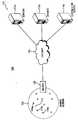
도 1은 본 발명에 일 실시예에 따른 유비쿼터스 네트워크 시스템을 나타내는 도면이다.1 is a diagram illustrating a ubiquitous network system according to an embodiment of the present invention.
도 1을 참조하면, 유비쿼터스 네트워크 시스템(100)은 센서 노드(110)와 라우터(120)를 포함하는 센서 네트워크(150), 인터넷(160) 및 서버(170)를 포함한다.Referring to FIG. 1, the
센서 노드(100)는 센서 네트워크(150) 상의 센서를 의미하며 착탈 가능한 메모리 장치를 연결할 수 있다. 예를 들어, 센서 노드(100)는 온도 센서 노드(110a), 방범 센서 노드(110b) 및 지문 인식 센서 노드(110c)를 포함할 수 있다.The
라우터(120)는 센서 노드(110)가 서버(170)에 데이터를 전송하거나 서버(170)가 센서 노드(100)에 데이터를 전송할 때 사용되는 장치를 의미하며 착탈 가능한 메모리 장치를 연결할 수 있다. 예를 들어, 온도 센서 노드(110a)가 서버(170)를 연결할 때 온도 센서 노드(110a)는 라우터(120)를 경유하여 서버(170)에 연결될 수 있다.The
인터넷(160)은 통신 네트워크의 일 실시예에 상응하는 것으로 IP(Internet Protocol)를 사용하는 네트워크만을 의미하는 것으로 해석되지 않는다.The
서버(170)는 센서 노드(100)로부터 정보를 입력받거나 센서 노드(100)에 정보를 전송한다. 예를 들어, 서버(170)는 온도 센서 노드(110a)로부터 온도 정보를 입력받아, 온도 정보를 기초로 에어콘 또는 히터 등을 동작시키거나 온도 센서 노드(110a)의 임계치를 설정할 수 있다.The server 170 receives information from the
우선 도 6 내지 8을 참조하여 유비쿼터스 네트워크 시스템이 구성될 때 필요한 데이터 구조를 설명하기로 한다.First, a data structure required when a ubiquitous network system is configured will be described with reference to FIGS. 6 to 8.
도 6은 유비쿼터스 네트워크 시스템이 구성될 때 필요한 센서 네트워크 구성 정보를 나타내는 데이터 구조이다.6 is a data structure illustrating sensor network configuration information required when a ubiquitous network system is configured.
센서 네트워크 구성 정보는 자동으로 유비쿼터스 네트워크 시스템이 구성될 때 필요한 정보에 상응하고 착탈 가능한 메모리 장치에 저장된다. 즉, 센서 네트워크 구성 정보(600)는 센서 네트워크의 식별자를 나타내는 센서 네트워크 아이디(610)를 포함하고, 센서 노드(110)에 필요한 서버 정보 및/또는 센서 네트워크의 보안에 필요한 보안 정보에 관한 보조 정보 블록(620)을 더 포함할 수 있다.The sensor network configuration information is automatically stored in a removable memory device corresponding to the information required when the ubiquitous network system is configured. That is, the sensor
예를 들어, 센서 네트워크 아이디(610)는 착탈 가능한 메모리 장치의 고유 시리얼 넘버에 상응할 수 있고, 보조 정보 블록(620)은 센서 노드(110)에 필요한서버 정보를 위한 서버 정보 목록(624)과 센서 네트워크의 보안을 위한 센서 노드 정보 목록(628)을 포함할 수 있다.For example, the
도 7은 유비쿼터스 네트워크 시스템이 구성될 때 필요한 라우터 구성 정보를 나타내는 데이터 구조이다.7 is a data structure illustrating router configuration information required when a ubiquitous network system is configured.
라우터 구성 정보(700)는 라우터(120)의 식별자를 나타내는 라우터 아이디(710)와 라우터(120)의 정보를 나타내는 라우터 정보 블록(720)을 포함하고, 센서 네트워크 구성 정보(600) 중 필요한 부분을 저장하기 위한 라우터 구성 정보 블록(730)을 포함할 수 있다. 한편, 라우터 구성 정보 블록(730)은 필요에 따라 센서 네트워크 구성 정보(600)를 수정할 수 있다.The
예를 들어, 라우터 구성 정보 블록(730)은 센서 네트워크 아이디(610)를 포함하고, 필요에 따라 센서 노드(110)에 필요한 서버 정보 및/또는 센서 네트워크의 보안에 필요한 보안 정보에 관한 보조 정보 블록(620)을 더 포함할 수 있다.For example, the router configuration information block 730 includes a
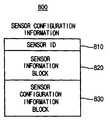
도 8은 유비쿼터스 네트워크 시스템이 구성될 때 필요한 센서 노드 구성 정보를 나타내는 데이터 구조이다.8 is a data structure illustrating sensor node configuration information required when a ubiquitous network system is configured.
센서 노드 구성 정보(800)는 센서 노드(110)의 식별자를 나타내는 센서 아이디(810)와센서(110)의 기능과 같은 센서(110)의 정보를 나타내는 센서 정보 블록(820)을 포함하고, 센서 네트워크 구성 정보(600) 중 필요한 부분을 저장하기 위한 센서 구성 정보 블록(830)을 포함할 수 있다. 한편, 센서 구성 정보 블록(830)은 필요에 따라 센서 네트워크 구성 정보(600)를 수정할 수 있다.The sensor
예를 들어, 센서 구성 정보 블록(830)은 센서 네트워크 아이디(610)를포함하고, 필요에 따라 센서 노드(110)에 필요한 서버 정보 및/또는 센서 네트워크의 보안에 필요한 보안 정보에 관한 보조 정보 블록(620)을 더 포함할 수 있다.For example, the sensor configuration information block 830 includes a
이하, 도 2 내지 도 5를 참조하여 유비쿼터스 네트워크 시스템을 구성하는 방법을 설명하기로 한다.Hereinafter, a method of configuring a ubiquitous network system will be described with reference to FIGS. 2 to 5.
도 2는 본 발명의 제1 실시예에 따른 유비쿼터스 네트워크 시스템을 구성하는 방법을 나타내는 흐름도이다.2 is a flowchart illustrating a method of configuring a ubiquitous network system according to a first embodiment of the present invention.
라우터(120)는 착탈 가능한 메모리 장치로부터 센서 네트워크 아이디(610)를 포함하는 센서 네트워크 구성 정보를 입력 받는다(단계 S210).The
센서 노드(110)는 착탈 가능한 메모리 장치로부터 센서 네트워크 아이디(610)를 포함하는 센서 네트워크 구성 정보를 입력 받는다(단계 S220).The
센서 노드(110) 및 라우터(120)는 센서 네트워크 아이디(610)를 기초로 센서 네트워크를 구성한다(단계 S230). 즉, 센서 노드(110)는 자신의 센서 네트워크 아이디(610)를 기초로 라우터(120)를 연결하고 라우터(120) 또한 자신의 센서 네트워크 아이디(610)를기초로 센서 노드(110)를 연결한다.The
한편, 서버(170)(예를 들어, 커스터마이징 서버(170c))는 유비쿼터스 네트워크 시스템을 커스터마이징(customizing)할 수 있다. 예를 들어, 라우터(120)에 등록된 센서 노드(110)의 정보 또는 센서 노드(110)의 동작 상태 등을 체크할 수 있다.Meanwhile, the server 170 (eg, the
결과적으로, 센서 네트워크 구성 정보를 포함하는 착탈 가능한 메모리 장치를 이용하여 자동으로 유비쿼터스 네트워크 시스템이 구성될 수 있다.As a result, the ubiquitous network system can be automatically configured using the removable memory device including the sensor network configuration information.
도 3은 본 발명의 제2 실시예에 따른 유비쿼터스 네트워크 시스템을 구성하는 방법을 나타내는 흐름도이다.3 is a flowchart illustrating a method of configuring a ubiquitous network system according to a second embodiment of the present invention.
라우터(120)는 착탈 가능한 메모리 장치로부터 센서 네트워크 아이디(610) 및 서버 정보 목록(624)을 포함하는 센서 네트워크 구성 정보를 입력 받는다(단계 S310).The
라우터(120)는 서버 정보 목록을 기초로 서버 네트워크를 구성한다(단계 S320). 서버 네트워크란 센서 노드(110)와 센서 노드(110)와 통신하는 서버(170)(예를 들어, 서버(710a)) 간의 네트워크를 의미한다. 예를 들어, 라우터(120)는 센서 노드(110a)의 기능을 기초로 적절한 서버(170a)를 결정하여 센서 노드(110a)로부터 입력된 데이터를 결정된 서버(170a)에 전송할 수 있다.The
센서 노드(110)는 착탈 가능한 메모리 장치로부터 센서 네트워크 아이디(610)를 포함하는 센서 네트워크 구성 정보를 입력 받는다(단계 S330).The
센서 노드(110) 및 라우터(120)는 센서 네트워크 아이디(610)를 기초로 센서 네트워크를 구성한다(단계 S340). 즉, 센서 노드(110)는 자신의 센서 네트워크 아이디(610)를 기초로 라우터(120)를 연결하고 라우터(120) 또한 자신의 센서 네트워크 아이디(610)를기초로 센서 노드(110)를 연결한다.The
한편, 서버(170)(예를 들어, 커스터마이징 서버(170c))는 유비쿼터스 네트워크 시스템을 커스터마이징(customizing)할 수 있다. 예를 들어, 라우터(120)에 등록된 센서 노드(110)의 정보 또는 센서 노드(110)의 동작 상태 등을 체크할 수 있다.Meanwhile, the server 170 (eg, the
결과적으로, 센서 네트워크 구성 정보를 포함하는 착탈 가능한 메모리 장치를 이용하여 자동으로 유비쿼터스 네트워크 시스템이 구성될 수 있다.As a result, the ubiquitous network system can be automatically configured using the removable memory device including the sensor network configuration information.
도 4는 본 발명의 제3 실시예에 따른 유비쿼터스 네트워크 시스템을 구성하는 방법을 나타내는 흐름도이다.4 is a flowchart illustrating a method of configuring a ubiquitous network system according to a third embodiment of the present invention.
라우터(120)는 착탈 가능한 메모리 장치로부터 센서 네트워크 아이디(610)를 포함하는 센서 네트워크 구성 정보를 입력 받는다(단계 S410).The
센서 노드(110)는 착탈 가능한 메모리 장치로부터 센서 네트워크 아이디(610) 및 서버 정보 목록(624)을 포함하는 센서 네트워크 구성 정보를 입력 받는다(단계 S420).The
센서 노드(110)는 서버 정보 목록을 기초로 서버 네트워크를 구성한다(단계 S430). 서버 네트워크란 센서 노드(110)와 센서 노드(110)와 통신하는 서버(170)(예를 들어, 서버(710a)) 간의 네트워크를 의미한다. 예를 들어, 센서 노드(110)는 자신의 기능을 기초로 적절한 서버(170a)를 결정하여 결정된 서버(170a)에 데이터를 전송할 수 있다.The
센서 노드(110) 및 라우터(120)는 센서 네트워크 아이디(610)를 기초로 센서 네트워크를 구성한다(단계 S440). 즉, 센서 노드(110)는 자신의 센서 네트워크 아이디(610)를 기초로 라우터(120)를 연결하고 라우터(120) 또한 자신의 센서 네트워크 아이디(610)를기초로 센서 노드(110)를 연결한다.The
한편, 서버(170)(예를 들어, 커스터마이징 서버(170c))는 유비쿼터스 네트워크 시스템을 커스터마이징(customizing)할 수 있다. 예를 들어, 라우터(120)에 등록된 센서 노드(110)의 정보 또는 센서 노드(110)의 동작 상태 등을 체크할 수 있다.Meanwhile, the server 170 (eg, the
결과적으로, 센서 네트워크 구성 정보를 포함하는 착탈 가능한 메모리 장치를 이용하여 자동으로 유비쿼터스 네트워크 시스템이 구성될 수 있다.As a result, the ubiquitous network system can be automatically configured using the removable memory device including the sensor network configuration information.
도 5는 본 발명의 제4 실시예에 따른 유비쿼터스 네트워크 시스템을 구성하는 방법을 나타내는 흐름도이다.5 is a flowchart illustrating a method of configuring a ubiquitous network system according to a fourth embodiment of the present invention.
라우터(120)는 착탈 가능한 메모리 장치로부터 센서 네트워크 아이디(610) 및 센서 노드 정보 목록(628)을 포함하는 센서 네트워크 구성 정보를 입력 받는다(단계 S510).The
센서 노드(110)는 착탈 가능한 메모리 장치로부터 센서 네트워크 아이디(610)를 포함하는 센서 네트워크 구성 정보를 입력 받는다(단계 S520).The
센서 노드(110) 및 라우터(120)는 센서 네트워크 아이디(610)를 기초로 센서 네트워크를 구성한다. 즉, 센서 노드(110)는 센서 네트워크 아이디(610)를 기초로 라우터(120)를 연결하고(단계 S530), 라우터(120)는 센서 노드 정보 목록(628)을 기초로 센서 네트워크(150)를 구성한다(단계 S540). 예를 들어, 센서 노드 정보 목록(628)은 센서 네트워크(150)의 보안을 위하여 사용될 수 있다.The
따라서 센서 노드 정보 목록(628)에 포함된 센서 노드(110)와 라우터(120)를 기초로 센서 네트워크(150)가 구성될 수 있다.Accordingly, the
결과적으로, 센서 네트워크 구성 정보를 포함하는 착탈 가능한 메모리 장치를 이용하여 자동으로 유비쿼터스 네트워크 시스템이 구성될 수 있다.As a result, the ubiquitous network system can be automatically configured using the removable memory device including the sensor network configuration information.
본 발명의 실시예들에 따라 센서 네트워크 구성 정보를 포함하는 착탈 가능한 메모리 장치를 이용하여 자동으로 유비쿼터스 네트워크 시스템을 구성할 수 있다. 또한, 본 발명의 실시예들에 따라 센서 네트워크 구성 정보에 포함된 서버 정 보 목록 및/또는 센서 노드 정보 목록을 이용하여 유비쿼터스 네트워크 시스템을 재구성할 수 있다.According to embodiments of the present invention, a ubiquitous network system may be automatically configured using a removable memory device including sensor network configuration information. In addition, according to embodiments of the present invention, the ubiquitous network system may be reconfigured using the server information list and / or the sensor node information list included in the sensor network configuration information.
상기에서는 본 발명의 바람직한 실시예를 참조하여 설명하였지만, 해당 기술 분야의 숙련된 당업자는 하기의 특허 청구의 범위에 기재된 본 발명의 사상 및 영역으로부터 벗어나지 않는 범위 내에서 본 발명을 다양하게 수정 및 변경시킬 수 있음을 이해할 수 있을 것이다.It will be apparent to those skilled in the art that various modifications and variations can be made in the present invention without departing from the spirit or scope of the present invention as defined by the following claims It can be understood that
Claims (13)
Translated fromKoreanApplications Claiming Priority (1)
| Application Number | Priority Date | Filing Date | Title |
|---|---|---|---|
| PCT/KR2007/002850WO2008153232A1 (en) | 2007-06-13 | 2007-06-13 | Ubiquitous sensor network system and method of configuring the same |
Publications (2)
| Publication Number | Publication Date |
|---|---|
| KR20100004951A KR20100004951A (en) | 2010-01-13 |
| KR101091696B1true KR101091696B1 (en) | 2011-12-08 |
Family
ID=40129826
Family Applications (1)
| Application Number | Title | Priority Date | Filing Date |
|---|---|---|---|
| KR1020097016499AExpired - Fee RelatedKR101091696B1 (en) | 2007-06-13 | 2007-06-13 | Ubiquitous sensor network system and method of configuring the same |
Country Status (3)
| Country | Link |
|---|---|
| US (1) | US8756299B2 (en) |
| KR (1) | KR101091696B1 (en) |
| WO (1) | WO2008153232A1 (en) |
Families Citing this family (74)
| Publication number | Priority date | Publication date | Assignee | Title |
|---|---|---|---|---|
| US11343380B2 (en) | 2004-03-16 | 2022-05-24 | Icontrol Networks, Inc. | Premises system automation |
| US9729342B2 (en) | 2010-12-20 | 2017-08-08 | Icontrol Networks, Inc. | Defining and implementing sensor triggered response rules |
| US20090077623A1 (en) | 2005-03-16 | 2009-03-19 | Marc Baum | Security Network Integrating Security System and Network Devices |
| US10522026B2 (en) | 2008-08-11 | 2019-12-31 | Icontrol Networks, Inc. | Automation system user interface with three-dimensional display |
| US10348575B2 (en) | 2013-06-27 | 2019-07-09 | Icontrol Networks, Inc. | Control system user interface |
| US11201755B2 (en) | 2004-03-16 | 2021-12-14 | Icontrol Networks, Inc. | Premises system management using status signal |
| US10237237B2 (en) | 2007-06-12 | 2019-03-19 | Icontrol Networks, Inc. | Communication protocols in integrated systems |
| US11677577B2 (en) | 2004-03-16 | 2023-06-13 | Icontrol Networks, Inc. | Premises system management using status signal |
| JP2007529826A (en) | 2004-03-16 | 2007-10-25 | アイコントロール ネットワークス, インコーポレイテッド | Object management network |
| US11489812B2 (en) | 2004-03-16 | 2022-11-01 | Icontrol Networks, Inc. | Forming a security network including integrated security system components and network devices |
| US7711796B2 (en) | 2006-06-12 | 2010-05-04 | Icontrol Networks, Inc. | Gateway registry methods and systems |
| US10142392B2 (en) | 2007-01-24 | 2018-11-27 | Icontrol Networks, Inc. | Methods and systems for improved system performance |
| US20170118037A1 (en) | 2008-08-11 | 2017-04-27 | Icontrol Networks, Inc. | Integrated cloud system for premises automation |
| US11244545B2 (en) | 2004-03-16 | 2022-02-08 | Icontrol Networks, Inc. | Cross-client sensor user interface in an integrated security network |
| US11368429B2 (en) | 2004-03-16 | 2022-06-21 | Icontrol Networks, Inc. | Premises management configuration and control |
| US10339791B2 (en) | 2007-06-12 | 2019-07-02 | Icontrol Networks, Inc. | Security network integrated with premise security system |
| US11316958B2 (en) | 2008-08-11 | 2022-04-26 | Icontrol Networks, Inc. | Virtual device systems and methods |
| US10062273B2 (en) | 2010-09-28 | 2018-08-28 | Icontrol Networks, Inc. | Integrated security system with parallel processing architecture |
| US11277465B2 (en) | 2004-03-16 | 2022-03-15 | Icontrol Networks, Inc. | Generating risk profile using data of home monitoring and security system |
| US10156959B2 (en) | 2005-03-16 | 2018-12-18 | Icontrol Networks, Inc. | Cross-client sensor user interface in an integrated security network |
| US12063220B2 (en) | 2004-03-16 | 2024-08-13 | Icontrol Networks, Inc. | Communication protocols in integrated systems |
| US9141276B2 (en) | 2005-03-16 | 2015-09-22 | Icontrol Networks, Inc. | Integrated interface for mobile device |
| US10721087B2 (en) | 2005-03-16 | 2020-07-21 | Icontrol Networks, Inc. | Method for networked touchscreen with integrated interfaces |
| US11916870B2 (en) | 2004-03-16 | 2024-02-27 | Icontrol Networks, Inc. | Gateway registry methods and systems |
| US11811845B2 (en) | 2004-03-16 | 2023-11-07 | Icontrol Networks, Inc. | Communication protocols over internet protocol (IP) networks |
| US11582065B2 (en) | 2007-06-12 | 2023-02-14 | Icontrol Networks, Inc. | Systems and methods for device communication |
| US11615697B2 (en) | 2005-03-16 | 2023-03-28 | Icontrol Networks, Inc. | Premise management systems and methods |
| US10999254B2 (en) | 2005-03-16 | 2021-05-04 | Icontrol Networks, Inc. | System for data routing in networks |
| US20120324566A1 (en) | 2005-03-16 | 2012-12-20 | Marc Baum | Takeover Processes In Security Network Integrated With Premise Security System |
| US11496568B2 (en) | 2005-03-16 | 2022-11-08 | Icontrol Networks, Inc. | Security system with networked touchscreen |
| US11700142B2 (en) | 2005-03-16 | 2023-07-11 | Icontrol Networks, Inc. | Security network integrating security system and network devices |
| US20170180198A1 (en) | 2008-08-11 | 2017-06-22 | Marc Baum | Forming a security network including integrated security system components |
| US20110128378A1 (en) | 2005-03-16 | 2011-06-02 | Reza Raji | Modular Electronic Display Platform |
| US10079839B1 (en) | 2007-06-12 | 2018-09-18 | Icontrol Networks, Inc. | Activation of gateway device |
| US12063221B2 (en) | 2006-06-12 | 2024-08-13 | Icontrol Networks, Inc. | Activation of gateway device |
| JP4839152B2 (en)* | 2006-08-04 | 2011-12-21 | 株式会社日立製作所 | Sensor network system and sensor network data processing method |
| US11706279B2 (en) | 2007-01-24 | 2023-07-18 | Icontrol Networks, Inc. | Methods and systems for data communication |
| US7633385B2 (en) | 2007-02-28 | 2009-12-15 | Ucontrol, Inc. | Method and system for communicating with and controlling an alarm system from a remote server |
| US8451986B2 (en) | 2007-04-23 | 2013-05-28 | Icontrol Networks, Inc. | Method and system for automatically providing alternate network access for telecommunications |
| US11646907B2 (en) | 2007-06-12 | 2023-05-09 | Icontrol Networks, Inc. | Communication protocols in integrated systems |
| US12283172B2 (en) | 2007-06-12 | 2025-04-22 | Icontrol Networks, Inc. | Communication protocols in integrated systems |
| US11237714B2 (en) | 2007-06-12 | 2022-02-01 | Control Networks, Inc. | Control system user interface |
| US11212192B2 (en) | 2007-06-12 | 2021-12-28 | Icontrol Networks, Inc. | Communication protocols in integrated systems |
| US11423756B2 (en) | 2007-06-12 | 2022-08-23 | Icontrol Networks, Inc. | Communication protocols in integrated systems |
| US12184443B2 (en) | 2007-06-12 | 2024-12-31 | Icontrol Networks, Inc. | Controlling data routing among networks |
| US11316753B2 (en) | 2007-06-12 | 2022-04-26 | Icontrol Networks, Inc. | Communication protocols in integrated systems |
| US11601810B2 (en) | 2007-06-12 | 2023-03-07 | Icontrol Networks, Inc. | Communication protocols in integrated systems |
| US10523689B2 (en) | 2007-06-12 | 2019-12-31 | Icontrol Networks, Inc. | Communication protocols over internet protocol (IP) networks |
| US11218878B2 (en) | 2007-06-12 | 2022-01-04 | Icontrol Networks, Inc. | Communication protocols in integrated systems |
| US12003387B2 (en) | 2012-06-27 | 2024-06-04 | Comcast Cable Communications, Llc | Control system user interface |
| US11831462B2 (en) | 2007-08-24 | 2023-11-28 | Icontrol Networks, Inc. | Controlling data routing in premises management systems |
| US11916928B2 (en) | 2008-01-24 | 2024-02-27 | Icontrol Networks, Inc. | Communication protocols over internet protocol (IP) networks |
| US20170185278A1 (en) | 2008-08-11 | 2017-06-29 | Icontrol Networks, Inc. | Automation system user interface |
| US10530839B2 (en) | 2008-08-11 | 2020-01-07 | Icontrol Networks, Inc. | Integrated cloud system with lightweight gateway for premises automation |
| US11792036B2 (en) | 2008-08-11 | 2023-10-17 | Icontrol Networks, Inc. | Mobile premises automation platform |
| US11258625B2 (en) | 2008-08-11 | 2022-02-22 | Icontrol Networks, Inc. | Mobile premises automation platform |
| US11758026B2 (en) | 2008-08-11 | 2023-09-12 | Icontrol Networks, Inc. | Virtual device systems and methods |
| US11729255B2 (en) | 2008-08-11 | 2023-08-15 | Icontrol Networks, Inc. | Integrated cloud system with lightweight gateway for premises automation |
| US8638211B2 (en) | 2009-04-30 | 2014-01-28 | Icontrol Networks, Inc. | Configurable controller and interface for home SMA, phone and multimedia |
| US8836467B1 (en) | 2010-09-28 | 2014-09-16 | Icontrol Networks, Inc. | Method, system and apparatus for automated reporting of account and sensor zone information to a central station |
| US11750414B2 (en) | 2010-12-16 | 2023-09-05 | Icontrol Networks, Inc. | Bidirectional security sensor communication for a premises security system |
| US9147337B2 (en) | 2010-12-17 | 2015-09-29 | Icontrol Networks, Inc. | Method and system for logging security event data |
| US8947239B1 (en) | 2012-03-05 | 2015-02-03 | Fitbit, Inc. | Near field communication system, and method of operating same |
| US11405463B2 (en) | 2014-03-03 | 2022-08-02 | Icontrol Networks, Inc. | Media content management |
| US11146637B2 (en) | 2014-03-03 | 2021-10-12 | Icontrol Networks, Inc. | Media content management |
| US11722365B2 (en)* | 2014-05-13 | 2023-08-08 | Senseware, Inc. | System, method and apparatus for configuring a node in a sensor network |
| US9756511B1 (en) | 2014-05-13 | 2017-09-05 | Senseware, Inc. | System, method and apparatus for wireless sensor network configuration |
| US20150373555A1 (en)* | 2014-06-23 | 2015-12-24 | Bin Xu | Wireless Sensor Network Commissioning |
| US9497200B2 (en) | 2015-02-16 | 2016-11-15 | International Business Machines Corporation | Managing limited network access configuration |
| US9986411B1 (en)* | 2016-03-09 | 2018-05-29 | Senseware, Inc. | System, method and apparatus for node selection of a sensor network |
| US10467890B2 (en) | 2016-05-13 | 2019-11-05 | Microsoft Technology Licensing, Llc | Secured sensor interface |
| US11210323B2 (en) | 2018-04-27 | 2021-12-28 | Microsoft Technology Licensing, Llc | Methods and systems for generating property keys corresponding to physical spaces, devices, and/or users |
| KR102708782B1 (en)* | 2018-05-15 | 2024-09-24 | 삼성전자주식회사 | A method and a electronic device connecting a plurality of electronic devices to a server through a hub |
| US11456915B2 (en)* | 2018-05-21 | 2022-09-27 | Microsoft Technology Licensing, Llc | Device model templates |
Family Cites Families (18)
| Publication number | Priority date | Publication date | Assignee | Title |
|---|---|---|---|---|
| US5774668A (en)* | 1995-06-07 | 1998-06-30 | Microsoft Corporation | System for on-line service in which gateway computer uses service map which includes loading condition of servers broadcasted by application servers for load balancing |
| US6437692B1 (en)* | 1998-06-22 | 2002-08-20 | Statsignal Systems, Inc. | System and method for monitoring and controlling remote devices |
| US20040075738A1 (en)* | 1999-05-12 | 2004-04-22 | Sean Burke | Spherical surveillance system architecture |
| JP2004266453A (en)* | 2003-02-28 | 2004-09-24 | Toshiba Corp | Network system, server device and communication method |
| US7701858B2 (en)* | 2003-07-17 | 2010-04-20 | Sensicast Systems | Method and apparatus for wireless communication in a mesh network |
| US7099770B2 (en)* | 2003-09-08 | 2006-08-29 | Axonn L.L.C. | Location monitoring and transmitting device, method, and computer program product using a simplex satellite transmitter |
| US7328045B2 (en)* | 2003-12-24 | 2008-02-05 | Robert Bosch Gmbh | Secure and intuitive method for wireless network set-up and associated device and system |
| US7423527B2 (en)* | 2004-02-13 | 2008-09-09 | Blue Vector Systems | Radio frequency identification (RFID) network system and method |
| KR100627328B1 (en)* | 2004-05-12 | 2006-09-25 | 전자부품연구원 | Energy efficient data merging method of sensor network |
| US7817994B2 (en)* | 2004-09-20 | 2010-10-19 | Robert Bosch Gmbh | Secure control of wireless sensor network via the internet |
| US20060143439A1 (en)* | 2004-12-06 | 2006-06-29 | Xpaseo | Method and system for sensor data management |
| KR100619099B1 (en)* | 2004-12-24 | 2006-08-31 | (주)노매딕텍스 | Network Clustering Devices and Network Clustering Methods Used in Wireless Mobile Communication Networks |
| US7717342B2 (en)* | 2005-08-26 | 2010-05-18 | Hand Held Products, Inc. | Data collection device having dynamic access to multiple wireless networks |
| JPWO2007066637A1 (en)* | 2005-12-05 | 2009-05-21 | 日本電気株式会社 | Wireless communication method and wireless communication system |
| US20070133469A1 (en)* | 2005-12-08 | 2007-06-14 | Electronics And Telecommunications Rsearch Institute | Sensor node device and method for supporting mobility of mobile node in sensor network |
| JP2007312056A (en)* | 2006-05-18 | 2007-11-29 | Oki Electric Ind Co Ltd | Radio communication system, network repeater, and communication method |
| US20080016440A1 (en)* | 2006-07-14 | 2008-01-17 | Microsoft Corporation | Programming And Managing Sensor Networks |
| US20080094205A1 (en)* | 2006-10-23 | 2008-04-24 | Octave Technology Inc. | Wireless sensor framework |
- 2007
- 2007-06-13KRKR1020097016499Apatent/KR101091696B1/ennot_activeExpired - Fee Related
- 2007-06-13USUS12/525,660patent/US8756299B2/enactiveActive
- 2007-06-13WOPCT/KR2007/002850patent/WO2008153232A1/enactiveApplication Filing
Also Published As
| Publication number | Publication date |
|---|---|
| US8756299B2 (en) | 2014-06-17 |
| KR20100004951A (en) | 2010-01-13 |
| US20100070618A1 (en) | 2010-03-18 |
| WO2008153232A1 (en) | 2008-12-18 |
Similar Documents
| Publication | Publication Date | Title |
|---|---|---|
| KR101091696B1 (en) | Ubiquitous sensor network system and method of configuring the same | |
| US20160285703A1 (en) | Cpe network configuration systems and methods | |
| CN104301141B (en) | A kind of method, apparatus and system for preserving configuration information | |
| CN110769033A (en) | Intelligent networking method and system | |
| CN107196793B (en) | IPTV networking system, first forwarding equipment and access point equipment | |
| CN108029155B (en) | mesh network node | |
| JP3877738B2 (en) | Apparatus and method for connecting individually existing networks | |
| US10193617B2 (en) | Relay method, relay system, recording medium, and method | |
| EP1915697B1 (en) | Image photographic apparatus | |
| CN110351141A (en) | FlexE interface managerial method, device and network element | |
| US9043178B2 (en) | Operating method of sensor node, operating method of data sink in sensor network, and sensor network | |
| US8938470B1 (en) | Managing and troubleshooting changes in device configurations on a network node | |
| JP4624443B2 (en) | Network device setting method | |
| CN107465582B (en) | Data sending method, device and system, physical home gateway and access node | |
| US20140204953A1 (en) | Communication System and Network Relay Device | |
| JP2016012909A (en) | Communication device, communication method and communication system | |
| CN106557037A (en) | Management method and managing device | |
| CN112468600B (en) | Application message notification method, system and storage medium based on network matrix | |
| CN107786441B (en) | Communication method, OpenFlow switch and communication system | |
| CN110380900B (en) | Network configuration system based on SDN | |
| JP2014127948A (en) | Communication program, communication system, and communication device | |
| CN104601679B (en) | Equipment soft method, mobile terminal and server | |
| WO2005039125A1 (en) | Home link setting method, home gateway device, and mobile terminal | |
| US20230336380A1 (en) | Method of operating a network | |
| TW201947911A (en) | Method of automatically building cloud services thereof |
Legal Events
| Date | Code | Title | Description |
|---|---|---|---|
| A201 | Request for examination | ||
| PA0105 | International application | St.27 status event code:A-0-1-A10-A15-nap-PA0105 | |
| PA0201 | Request for examination | St.27 status event code:A-1-2-D10-D11-exm-PA0201 | |
| N231 | Notification of change of applicant | ||
| P11-X000 | Amendment of application requested | St.27 status event code:A-2-2-P10-P11-nap-X000 | |
| P13-X000 | Application amended | St.27 status event code:A-2-2-P10-P13-nap-X000 | |
| PN2301 | Change of applicant | St.27 status event code:A-3-3-R10-R13-asn-PN2301 St.27 status event code:A-3-3-R10-R11-asn-PN2301 | |
| PG1501 | Laying open of application | St.27 status event code:A-1-1-Q10-Q12-nap-PG1501 | |
| E902 | Notification of reason for refusal | ||
| PE0902 | Notice of grounds for rejection | St.27 status event code:A-1-2-D10-D21-exm-PE0902 | |
| AMND | Amendment | ||
| P11-X000 | Amendment of application requested | St.27 status event code:A-2-2-P10-P11-nap-X000 | |
| P13-X000 | Application amended | St.27 status event code:A-2-2-P10-P13-nap-X000 | |
| N231 | Notification of change of applicant | ||
| PN2301 | Change of applicant | St.27 status event code:A-3-3-R10-R13-asn-PN2301 St.27 status event code:A-3-3-R10-R11-asn-PN2301 | |
| E601 | Decision to refuse application | ||
| PE0601 | Decision on rejection of patent | St.27 status event code:N-2-6-B10-B15-exm-PE0601 | |
| AMND | Amendment | ||
| E13-X000 | Pre-grant limitation requested | St.27 status event code:A-2-3-E10-E13-lim-X000 | |
| P11-X000 | Amendment of application requested | St.27 status event code:A-2-2-P10-P11-nap-X000 | |
| P13-X000 | Application amended | St.27 status event code:A-2-2-P10-P13-nap-X000 | |
| PX0901 | Re-examination | St.27 status event code:A-2-3-E10-E12-rex-PX0901 | |
| PX0701 | Decision of registration after re-examination | St.27 status event code:A-3-4-F10-F13-rex-PX0701 | |
| X701 | Decision to grant (after re-examination) | ||
| GRNT | Written decision to grant | ||
| PR0701 | Registration of establishment | St.27 status event code:A-2-4-F10-F11-exm-PR0701 | |
| PR1002 | Payment of registration fee | St.27 status event code:A-2-2-U10-U12-oth-PR1002 Fee payment year number:1 | |
| PG1601 | Publication of registration | St.27 status event code:A-4-4-Q10-Q13-nap-PG1601 | |
| R18-X000 | Changes to party contact information recorded | St.27 status event code:A-5-5-R10-R18-oth-X000 | |
| FPAY | Annual fee payment | Payment date:20140926 Year of fee payment:4 | |
| PR1001 | Payment of annual fee | St.27 status event code:A-4-4-U10-U11-oth-PR1001 Fee payment year number:4 | |
| PR1001 | Payment of annual fee | St.27 status event code:A-4-4-U10-U11-oth-PR1001 Fee payment year number:5 | |
| FPAY | Annual fee payment | Payment date:20161007 Year of fee payment:6 | |
| PR1001 | Payment of annual fee | St.27 status event code:A-4-4-U10-U11-oth-PR1001 Fee payment year number:6 | |
| FPAY | Annual fee payment | Payment date:20171011 Year of fee payment:7 | |
| PR1001 | Payment of annual fee | St.27 status event code:A-4-4-U10-U11-oth-PR1001 Fee payment year number:7 | |
| PR1001 | Payment of annual fee | St.27 status event code:A-4-4-U10-U11-oth-PR1001 Fee payment year number:8 | |
| PR1001 | Payment of annual fee | St.27 status event code:A-4-4-U10-U11-oth-PR1001 Fee payment year number:9 | |
| PC1903 | Unpaid annual fee | St.27 status event code:A-4-4-U10-U13-oth-PC1903 Not in force date:20201203 Payment event data comment text:Termination Category : DEFAULT_OF_REGISTRATION_FEE | |
| PC1903 | Unpaid annual fee | St.27 status event code:N-4-6-H10-H13-oth-PC1903 Ip right cessation event data comment text:Termination Category : DEFAULT_OF_REGISTRATION_FEE Not in force date:20201203 | |
| R18-X000 | Changes to party contact information recorded | St.27 status event code:A-5-5-R10-R18-oth-X000 |