KR101086054B1 - Meter test bench - Google Patents
Meter test benchDownload PDFInfo
- Publication number
- KR101086054B1 KR101086054B1KR1020090032318AKR20090032318AKR101086054B1KR 101086054 B1KR101086054 B1KR 101086054B1KR 1020090032318 AKR1020090032318 AKR 1020090032318AKR 20090032318 AKR20090032318 AKR 20090032318AKR 101086054 B1KR101086054 B1KR 101086054B1
- Authority
- KR
- South Korea
- Prior art keywords
- meter
- fixed block
- test
- inlet
- hole
- Prior art date
- Legal status (The legal status is an assumption and is not a legal conclusion. Google has not performed a legal analysis and makes no representation as to the accuracy of the status listed.)
- Expired - Fee Related
Links
Images


Classifications
- G—PHYSICS
- G01—MEASURING; TESTING
- G01D—MEASURING NOT SPECIALLY ADAPTED FOR A SPECIFIC VARIABLE; ARRANGEMENTS FOR MEASURING TWO OR MORE VARIABLES NOT COVERED IN A SINGLE OTHER SUBCLASS; TARIFF METERING APPARATUS; MEASURING OR TESTING NOT OTHERWISE PROVIDED FOR
- G01D11/00—Component parts of measuring arrangements not specially adapted for a specific variable
- G01D11/10—Elements for damping the movement of parts
- G01D11/12—Elements for damping the movement of parts using fluid damping
- G—PHYSICS
- G01—MEASURING; TESTING
- G01F—MEASURING VOLUME, VOLUME FLOW, MASS FLOW OR LIQUID LEVEL; METERING BY VOLUME
- G01F25/00—Testing or calibration of apparatus for measuring volume, volume flow or liquid level or for metering by volume
- G01F25/0092—Testing or calibration of apparatus for measuring volume, volume flow or liquid level or for metering by volume for metering by volume
- G—PHYSICS
- G01—MEASURING; TESTING
- G01D—MEASURING NOT SPECIALLY ADAPTED FOR A SPECIFIC VARIABLE; ARRANGEMENTS FOR MEASURING TWO OR MORE VARIABLES NOT COVERED IN A SINGLE OTHER SUBCLASS; TARIFF METERING APPARATUS; MEASURING OR TESTING NOT OTHERWISE PROVIDED FOR
- G01D11/00—Component parts of measuring arrangements not specially adapted for a specific variable
- G01D11/02—Bearings or suspensions for moving parts
Landscapes
- Physics & Mathematics (AREA)
- General Physics & Mathematics (AREA)
- Fluid Mechanics (AREA)
- Measuring Volume Flow (AREA)
- Examining Or Testing Airtightness (AREA)
Abstract
Translated fromKoreanDescription
Translated fromKorean본 발명은 계량기 검사대에 관한 것으로, 특히 복수의 시험계량기를 일체로 회전시키면서 검사할 수 있도록 구조가 개선된 계량기 검사대에 관한 것이다.TECHNICAL FIELD The present invention relates to a meter test bench, and more particularly, to a meter test bench having an improved structure so that a plurality of test meters can be inspected while being integrally rotated.
유체가 유입구를 통해 유입되어 배출구를 통하여 배출될 때, 그 유량을 적산하여 사용한 유량을 측정하는 계량기는 사용한 유량을 오차없이 정확하게 측정할 수 있는 것이어야 한다.When the fluid is introduced through the inlet and discharged through the outlet, the meter for measuring the flow rate used by integrating the flow rate should be able to accurately measure the flow rate used without error.
계량기를 이용하여 유량을 반복적으로 측정할 때, 그 유량이 허용가능한 오차 범위 내에 존재하여야 우수한 계량기라 할 수 있다.When measuring flow rate repeatedly using a meter, the flow rate must be within an acceptable error range to be an excellent meter.
또한, 이러한 계량기의 성능을 반복적으로 측정할 때 계량기 자체의 성능 문제뿐만 아니라 측정하는 설비가 계량기의 성능을 정확하게 측정하는 것이 중요하다.In addition, when measuring the performance of such a meter repeatedly, it is important that the measuring equipment accurately measure the performance of the meter as well as the performance problem of the meter itself.
계량기의 성능을 평가할 때, 시험대상이 되는 시험계량기에 유체를 흘려보내어 공급된 유체의 양과 시험계량기의 적산표시부에 표시된 유량의 오차를 측정하여 그 시험계량기의 성능을 평가하게 된다.When evaluating the performance of the meter, the fluid is sent to the test meter to be tested to measure the error between the amount of fluid supplied and the flow rate indicated on the integrated display of the test meter.
그런데, 시험계량기의 내부에 공기가 잔존하는 경우에, 유량의 반복측정시 재현성을 방해하여 정확한 반복측정의 장애가 된다.However, in the case where air remains inside the test meter, the reproducibility is impeded during repeated measurement of the flow rate, which is an obstacle of accurate repeat measurement.
이러한 문제를 해결하기 위하여, 시험계량기 내부의 공기를 빼내기 위하여, 시험계량기에 유체를 공급한 상태에서 시험계량기를 뒤짚고, 시험계량기의 내부 공간에 잔존하는 공기를 진공펌프로 빼내어 시험계량기의 잔존 공기를 제거하는 과정이 필요하며, 이때 다수의 시험계량기를 측정하는 검사대에서 그 다수의 시험계량기를 일체로 회전시키는 장치에 대한 요구가 있다.In order to solve this problem, in order to bleed the air inside the test meter, the test meter is turned over while the fluid is supplied to the test meter, and the remaining air in the test meter is drawn out with a vacuum pump to draw out the remaining air in the test meter. There is a need for a process for eliminating the need for a device that rotates the plurality of test meters integrally on a test bench measuring a plurality of test meters.
본 발명은 상술한 바와 같은 사항을 고려하여 안출된 것으로, 복수의 시험계량기의 성능을 동시에 측정하는 계량기 검사대에 있어서, 각 시험계량기의 잔존공기를 용이하게 빼내어 반복재현성을 향상시킬 수 있도록, 복수의 시험계량기를 일체로 회전시킬 수 있도록 구조가 개선된 계량기 검사대를 제공함을 그 목적으로 한다.SUMMARY OF THE INVENTION The present invention has been made in consideration of the above-described matters, and in a meter test bench that simultaneously measures the performance of a plurality of test weighers, the plurality of test weighers can be easily removed to improve reproducibility by removing residual air from each test weigher. Its purpose is to provide a meter test bench with an improved construction that allows the test meter to be rotated integrally.
상기와 같은 목적을 달성하기 위한 본 발명에 따른 계량기 검사대는, 유체가 유입 및 배출되는 유입구와 배출구를 구비하는 시험계량기를 복수개 검사하는 계량기 검사대에 있어서, 베이스와, 상기 베이스에 고정되며 유체가 공급되는 유입공이 형성된 제1 고정블럭과, 상기 베이스에 고정되며 상기 공급된 유체가 배출되는 배출공이 형성된 제2 고정블럭과, 상기 제1 고정블럭과 상기 제2 고정블럭 사이에 상호 이격배치되며 상기 유입공 및 상기 배출공과 동축적으로 배치되는 연결공이 형성된 복수의 연결블럭과, 상기 연결공에 회동가능하게 결합되는 중공의 연결봉과, 상기 제1 고정블럭과 그 제1 고정블럭에 인접한 상기 연결블럭 사이와, 상기 연결블럭들 사이와, 상기 제2 고정블럭과 그 제2 고정블럭에 인접한 상기 연결블럭사이에 연속적으로 결합되는 상기 시험계량기들을 일측으로 가압하여 밀착시키는 가압래버를 포함하며, 상기 시험계량기들과 상기 연결봉은 일체로 회전되는 것을 특징으로 한다.The meter test bench according to the present invention for achieving the above object, in the meter test bench for inspecting a plurality of test meters having an inlet and an outlet through which the fluid is introduced and discharged, the base, fixed to the base and the fluid supply A first fixed block having an inflow hole formed therein, a second fixed block fixed to the base and having a discharge hole through which the supplied fluid is discharged, and spaced apart from each other between the first fixed block and the second fixed block; A plurality of connection blocks having a ball and a connection hole coaxially disposed with the discharge hole, a hollow connection rod rotatably coupled to the connection hole, and the first fixed block and the connection block adjacent to the first fixed block. And between the connection blocks and between the second fixed block and the connection block adjacent to the second fixed block. Which includes a pressure contact and pressing the grabber to the test instrument to one side, characterized in that with the test instrument that the connecting rod is integrally rotated.
또한, 상기 제1 고정블럭의 유입공과 상기 시험계량기의 유입구를 연결시키는 제1 부시와, 상기 제2 고정블럭의 배출공과 상기 시험계량기의 배출구를 연결시키는 제2 부시와, 상기 제1,2 부시의 외주면에 결합되는 제1,2 베어링을 포함하는 것이 바람직하다.In addition, a first bush connecting the inlet of the first fixed block and the inlet of the test meter, a second bush connecting the outlet of the second fixed block and the outlet of the test meter, and the first and second bushes. It is preferable to include a first and a second bearing coupled to the outer peripheral surface of the.
또한, 상기 연결봉의 양단부 각각에는 상기 시험계량기의 유입구 및 배출구가 삽입체결되는 체결홈이 형성되고, 상기 제1 부시에는 상기 시험계량기의 유입구가 삽입체결되는 제1 결합홈이 형성되고, 상기 제2 부시에는 상기 시험계량기의 배출구가 삽입체결되는 제2 결합홈이 형성되며, 상기 체결홈과 상기 제1,2 결합홈에는 누수를 방지하는 패킹부재가 삽입되는 것이 바람직하다.In addition, each of the both ends of the connecting rod is formed with a fastening groove for inserting and fastening the inlet and outlet of the test meter, the first bush is formed with a first coupling groove for inserting and fastening the inlet of the test meter, the second The bush is formed with a second coupling groove into which the outlet of the test meter is fastened, and a packing member for preventing leakage is inserted into the coupling groove and the first and second coupling grooves.
또한, 상기 제1,2 부시의 외주면에는 누수를 방지하는 오링이 결합된 것이 바람직하다.In addition, the outer circumferential surface of the first and second bush is preferably coupled to the O-ring to prevent leakage.
또한, 상기 연결블럭을 일정간격으로 이격배치되며, 상기 베이스에 고정되는 것이 바람직하다.In addition, the connection block is spaced at a predetermined interval, it is preferable to be fixed to the base.
본 발명에 따른 계량기 검사대는, 연결봉을 통하여 연속적으로 배치되는 복수의 시험계량기가 연결봉과 함께 일체로 회전가능하므로 시험계량기에 잔존하는 공기를 용이하게 제거할 수 있도록 한다.The meter test bench according to the present invention, since the plurality of test meters continuously arranged through the connecting rod can be rotated integrally with the connecting rod so that the air remaining in the test meter can be easily removed.
본 발명에 따른 계량기 검사대는 시험계량기, 예컨대 수도계량기 등을 복수개 검사하는데 사용된다.The meter test bench according to the present invention is used to inspect a plurality of test meters, such as water meters.
이하, 본 발명에 따른 바람직한 실시예를 첨부된 도면을 참조하여 상세히 설명한다.Hereinafter, preferred embodiments according to the present invention will be described in detail with reference to the accompanying drawings.
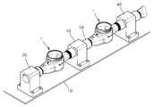
도1은 본 발명 실시예에 따른 계량기 검사대의 사시도이고, 도2는 도1의 Ⅱ-Ⅱ를 따라 절개한 단면도이다. 도3a 및 도3b는 도2에서 가압래버의 작동 전후의 단면도이다.1 is a perspective view of a meter inspection table according to an embodiment of the present invention, Figure 2 is a cross-sectional view taken along II-II of FIG. 3A and 3B are sectional views before and after the operation of the pressure lever in FIG.
도1을 참조하면, 본 실시예에 따른 계량기 검사대는 유체가 유입 및 배출되는 유입구(11)와 배출구(12)를 구비하는 시험계량기를 복수개 검사하는 것으로서, 베이스(10)와, 제1,2 고정블럭(20,30)과, 연결블럭(40)과, 연결봉(50)과, 가압래버(60)을 포함한다.Referring to FIG. 1, the meter test bench according to the present embodiment inspects a plurality of test meters including an
상기 베이스(10)에는 복수의 시험계량기가 장착된다.The
상기 제1 고정블럭(20)은 상기 베이스(10)에 고정되며, 유체가 공급되는 유입공(21)이 형성되고, 상기 제2 고정블럭(30)은 상기 베이스(10)에 고정되며, 상기 공급된 유체가 배출되는 배출공(31)이 형성된다.The first
상기 연결블럭(40)은 상기 제1 고정블럭(20)과 상기 제2 고정블럭(30) 사이에 복수개가 상호 이격배치되며, 상기 유입공(21) 및 상기 배출공(31)과 동축적으로 배치되는 연결공(41)이 형성된다.A plurality of
본 실시예에서, 상기 연결블럭(40)은 상기 제1 고정블럭(20)과 상기 제2 고정블럭(30) 사이에 일정간격으로 이격배치되며, 상기 베이스(10)에 고정 설치된다.In the present embodiment, the
상기 연결봉(50)은 일측에 시험계량기의 유입구(11)가 삽입체결되고, 타측에 시험계량기의 배출구(12)가 삽입 체결되도록 중공형으로 이루어지며, 상기 연결 봉(50)은 시험계량기와 함께 일체로 상기 연결공(41)에 회동가능하게 결합된다.The connecting
상기 연결봉(50)의 양단부 각각에는 상기 시험계량기의 유입구(11) 및 배출구(12)가 삽입체결되는 체결홈(51)이 형성된다.Fastening
상기 가압래버(60)는 상기 제1 고정블럭(20)과 그 제1 고정블럭에 인접한 상기 연결블럭(40) 사이와, 상기 연결블럭(40)들 사이와, 상기 제2 고정블럭(30)과 그 제2 고정블럭에 인접한 상기 연결블럭(40) 사이에 연속적으로 결합되는 상기 시험계량기(1)들을 일측으로 가압한다.The
본 실시예에서 상기 가압래버(60)는, 손잡이부(61)와 가압부(62)를 포함하여 구성된다.In the present embodiment, the
상기 손잡이부(61)는 상기 제2 고정블럭(30)에 힌지축(61a)을 중심으로 회동가능하게 결합되고, 상기 가압부(62)는 일단이 상기 손잡이부(61)에 회동가능하게 결합되고, 타단이 후술할 슬라이딩부재(130)에 회동가능하게 결합된다.The
본 실시예에 따른 계량기 검사대는, 제1 부시(70)와, 제2 부시(80)와, 제1,2 베어링(90,100)과, 슬라이딩부재(130)을 더 구비한다.The meter test bench according to the present embodiment further includes a
상기 제1 부시(70)는 상기 제1 고정블럭(20)의 유입공(21)과 상기 시험계량기의 유입구(11)를 연결시킨다. 상기 제1 부시(70)는 상기 유입공(21)에 삽입되지 않도록 유입공(21)의 내경보다 큰 외경을 갖는 제1 걸림부(72)와, 상기 유입공(21)에 회동가능하게 삽입되는 제1 삽입부(73)로 이루어지며, 상기 제1 걸림부(72)에는 상기 시험계량기의 유입구(11)가 삽입체결되는 제1 결합홈(71)이 형성된다.The
상기 슬라이딩부재(130)는 상기 가압래버(60)가 하방향으로 회동시 상기 배 출구(12) 외측으로 슬라이딩 되면서 상기 시험계량기를 일측으로 가압밀착시키는 중공형의 부재로서, 상기 배출구(12)에 삽입되는 슬라이딩부(131)와, 상기 배출구(12)에 삽입되지 않도록 배출구(12)의 내경보다 큰 외경을 가지며 상기 가압부재의 가압부(62)에 의해 가압되는 돌출턱(132)으로 이루어진다.The sliding
상기 제2 부시(80)는 상기 제2 고정블럭(30)의 배출공(31)과 상기 시험계량기의 배출구(12)를 연결시킨다. 상기 제2 부시(80)는 상기 슬라이딩부재(130)에 삽입되지 않는 제2 걸림부(82)와, 상기 슬라이딩부재(130)에 회도가능하게 삽입되는 제2 삽입부(83)로 이루어진다. 상기 제2 걸림부(82)에는 상기 시험계량기의 배출구(12)가 삽입체결되는 제2 결합홈(81)이 형성된다.The
상기 제1,2 베어링(90,100)은 상기 베이스(10)에 장착된 복수의 시험계량기를 일체로 180도 용이하게 회전시키기 위해서 마련된 것으로, 상기 제1,2 부시(70,80)의 외주면에 결합되며, 본 실시예에서 트러스트 볼 베어링이 사용된다.The first and
구체적으로, 상기 제1 베어링(90)은 상기 제1 고정부재의 외측면과 상기 제1 부시(70)의 제1 걸림부(72) 사이에서 상기 제1 부시(70)의 외주면에 결합된다.Specifically, the first bearing 90 is coupled to the outer circumferential surface of the
상기 제2 베어링(100)은 상기 슬라이등부재의 돌출턱(132)과 상기 제2 부시(80)의 제2 걸림부(82) 사이에서 상기 제2 부시(80)의 외주면에 결합된다.The second bearing 100 is coupled to the outer circumferential surface of the
한편, 본 실시예에 따른 계량기 검사대는 공급된 유체의 누수를 방지하기 위해서, 패킹부재(110)와 오링(120)을 더 구비한다.Meanwhile, the meter test bench according to the present embodiment further includes a
상기 패킹부재(110)는 상기 체결홈(51)과 상기 제1,2 결합홈(71,81)으로부터의 누수를 방지하게 위해서, 상기 체결홈(51)과 상기 제1,2 결합홈(71,81)에 삽입 된다.The
상기 오링(120)은 상기 제1 부시(70)의 외주면과 유입공(21) 사이와, 상기 제2 부시(80)의 외주면과 상기 슬라이딩부재(130) 사이를 통한 누수를 방지하기 위해서, 제1,2 부시(70,80)의 외주면에 결합된다.The O-
또한, 슬라이딩부재(130)의 슬라이딩부(131) 외주면에는 그 외주면과 배출공(31) 사이로부터의 누수를 방지하기 위한 오링(120)이 결합된다.In addition, the O-
이하, 상기 구성에 의한 본 실시예에 따른 계량기 검사대의 작용을 구체적으로 설명한다.Hereinafter, the operation of the meter inspection table according to the present embodiment by the above configuration will be described in detail.
먼저, 연결블럭(40)에 연결봉(50)에 삽입하고, 연결봉(50)의 양측에 각각 시험계량기의 유입구(11)와 배출구(12)를 끼워서 결합한다.First, the connecting
제1 고정블럭(20)과 연결블럭(40) 사이와, 연결블럭(40)과 연결블럭(40) 사이와, 제2 고정블럭(30)과 연결블럭(40) 사이에 시험계량기를 연속적으로 연결한다.The test meter is continuously connected between the first
그 후, 도3a의 상태에서 가압래버(60)를 하방으로 내리면 가압래버(60)의 가압부(62)가 슬라이딩부재(130)의 돌출턱(132)을 가압하여 슬라이딩부재(130)가 시험계량기 측으로 슬라이딩되면서, 도3b에 도시된 바와 같이 연속적으로 배치된 시험계량기가 일측으로 가압하여 밀착시킨다.Thereafter, when the
이어서, 유입공(21)을 통해 유체가 공급되면, 제1 고정블럭(20)에 인접한 시험계량기로부터 제2 고정블럭(30)에 인접한 시험계량기까지 유체가 순차적으로 흐르면서 시험계량기는 그 유량을 적산한다.Subsequently, when the fluid is supplied through the
이때, 시험계량기에 잔존하는 공기를 제거하기 위해서, 시험계량기 일체를 회전시키는 과정을 도4 및 도5를 참조하여 설명한다.At this time, in order to remove the air remaining in the test meter, a process of rotating the test meter unit will be described with reference to FIGS. 4 and 5.
도4에 도시된 바와 같이 시험계량기가 설치되는 원위치(시험계량기의 적산표시부(미도시)가 상측을 향하도록 연결된 상태)에서, 유입공(21)을 통해 공급된 유체가 제2 고정블럭(30)에 인접한 시험계량기를 통해 배출되면 유입공(21)과 배출공(31)을 일시적으로 폐쇄시키고, 시험계량기와 연결봉(50)을 파지하여 180도 회전시킨다.As shown in FIG. 4, the fluid supplied through the
이때, 가압래버(60)에 의해 시험계량기가 일측으로 가압되어 연결봉(50)의 체결홈(51)에 시험계량기가 견고하고 삽입체결된 상태를 유지하고, 연결봉(50)은 연결블럭(40)의 연결공(41)에 회동가능하게 결합되고 제1,2 부시(70,80)에는 베어링이 결합되어 있으므로, 시험계량기와 연결블럭(40)과 제1,2 부시(70,80)는 일체로 180도 회전된다.At this time, the test meter is pressed to one side by the
그러면, 도5와 같이 시험계량기가 뒤짚어진 상태(시험계량기의 적산표시부(미도시)가 하측으로 향하도록 배치된 상태)에서 시험계량기의 잔존하는 공기를 펌프를 이용하여 외부로 배출시킨다.Then, as shown in FIG. 5, the remaining air of the test meter is discharged to the outside by using a pump in a state where the test meter is inverted (a state in which the integration display part (not shown) of the test meter is disposed downward).
이어서, 다시 도4에 도시된 바와 같이 시험계량기의 적산표시부가 상측으로 향하도록 배치시키고, 유입공(21)과 배출공(31)을 개방시켜 유체가 흐르도록 한다.Subsequently, as shown in FIG. 4, the integrated display part of the test meter is disposed upward, and the
이와 같이, 시험계량기에 잔존하는 공기를 시험계량기를 뒤짚어 제거함으로써 시험계량기의 유량계측 성능을 보다 정확하게 측정할 수 있게 한다.In this way, the air remaining in the test meter is removed from the test meter by removing the test meter so as to more accurately measure the flow measurement performance of the test meter.
이처럼, 복수개의 시험계량기의 유량계측 성능을 동시에 검사하는 본 실시예 에 따른 계량기 검사대는, 복수의 시험계량기를 용이하게 180도 회전시키는 효과를 제공하여, 시험계량기의 유량계측 성능을 보다 정확하게 측정할 수 있게 한다.As such, the meter test bench according to the present embodiment, which simultaneously checks the flow measurement performance of the plurality of test meters, provides an effect of easily rotating the plurality of test meters by 180 degrees, thereby more accurately measuring the flow measurement performance of the test meter. To be able.
이상, 본 발명을 바람직한 실시예를 들어 상세하게 설명하였으나, 본 발명은 상기 실시예에 한정되지 않으며, 본 발명의 범주를 벗어나지 않는 범위 내에서 여러 가지 많은 변형이 제공될 수 있다.In the above, the present invention has been described in detail with reference to preferred embodiments, but the present invention is not limited to the above embodiments, and many other modifications can be provided without departing from the scope of the present invention.
도1은 본 발명 실시예에 따른 계량기 검사대의 사시도,1 is a perspective view of a meter inspection table according to an embodiment of the present invention,
도2는 도1의 Ⅱ-Ⅱ를 따라 절개한 단면도,2 is a cross-sectional view taken along the line II-II of FIG.
도3a 및 도3b는 본 발명 실시예에 채용된 가압래버의 작동전후 단면도,3a and 3b is a cross-sectional view before and after the operation of the pressure lever employed in the embodiment of the present invention,
도4 및 도5는 본 발명 실시예에 따른 계량기 검사대의 작동상태도이다.4 and 5 is an operating state diagram of the meter test bench according to an embodiment of the present invention.
<도면의 주요 부분에 대한 부호의 설명><Explanation of symbols for the main parts of the drawings>
1... 시험계량기 10... 베이스1 ...
20... 제1 고정블럭 30... 제2 고정블럭20 ... 1st fixed
40... 연결블럭 50... 연결봉40 ... connecting
60... 가압래버 70... 제1 부시60 ...
80... 제2 부시 90... 제1 베어링80 ...
100... 제2 베어링 110... 패킹부재100 ...
120... 오링120 ... O-ring
Claims (5)
Translated fromKoreanPriority Applications (1)
| Application Number | Priority Date | Filing Date | Title |
|---|---|---|---|
| KR1020090032318AKR101086054B1 (en) | 2009-04-14 | 2009-04-14 | Meter test bench |
Applications Claiming Priority (1)
| Application Number | Priority Date | Filing Date | Title |
|---|---|---|---|
| KR1020090032318AKR101086054B1 (en) | 2009-04-14 | 2009-04-14 | Meter test bench |
Publications (2)
| Publication Number | Publication Date |
|---|---|
| KR20100113806A KR20100113806A (en) | 2010-10-22 |
| KR101086054B1true KR101086054B1 (en) | 2011-11-22 |
Family
ID=43133200
Family Applications (1)
| Application Number | Title | Priority Date | Filing Date |
|---|---|---|---|
| KR1020090032318AExpired - Fee RelatedKR101086054B1 (en) | 2009-04-14 | 2009-04-14 | Meter test bench |
Country Status (1)
| Country | Link |
|---|---|
| KR (1) | KR101086054B1 (en) |
Families Citing this family (5)
| Publication number | Priority date | Publication date | Assignee | Title |
|---|---|---|---|---|
| US9891089B2 (en)* | 2013-04-15 | 2018-02-13 | OW Investors, LLC. | Modular fluid meter test bench |
| TWI582896B (en)* | 2015-08-18 | 2017-05-11 | 由田新技股份有限公司 | Air bearing platform |
| CN105737870B (en)* | 2016-04-15 | 2018-05-04 | 洛阳功航机械科技有限公司 | A kind of across hydraulic condition of river detection device |
| KR102025565B1 (en)* | 2017-07-06 | 2019-09-27 | (주)에프엔씨 | Connecting device for perfomance test of water meter |
| CN110631666A (en)* | 2019-10-25 | 2019-12-31 | 怀化建南机器厂有限公司 | A water meter pulse anomaly detection device |
- 2009
- 2009-04-14KRKR1020090032318Apatent/KR101086054B1/ennot_activeExpired - Fee Related
Also Published As
| Publication number | Publication date |
|---|---|
| KR20100113806A (en) | 2010-10-22 |
Similar Documents
| Publication | Publication Date | Title |
|---|---|---|
| KR101086054B1 (en) | Meter test bench | |
| CN102589938B (en) | Converter gas hand-operated sampling device | |
| CN104865109A (en) | Quantitative air inlet method of transformer oil and sample compounding device thereof | |
| CN108426811B (en) | Full-automatic formaldehyde concentration detection equipment and control method thereof | |
| KR200463311Y1 (en) | Apparatus for check leakage, measuring torque and test reliability of butterfly valve | |
| CN117804691A (en) | A pump body air tightness detection device | |
| CN112857694A (en) | Movable constant-pressure sealing detection system | |
| CN206848111U (en) | Normal temperature and pressure gas solubility determines device | |
| CN103521480A (en) | Automatic sampling needle cleaning device and method | |
| CN108398366B (en) | A comprehensive detection and analysis system and method for compressed air quality in a power plant | |
| CN104730284B (en) | Sampling wind speed monitoring device and enthalpy difference method experiment detection equipment with same | |
| CN101806789B (en) | Dissolved Inorganic Carbon Concentration Analyzer in Water | |
| CN206192571U (en) | Type of falling U pipe differential gauge | |
| CN202494591U (en) | Converter gas manual sampling device | |
| CN204666420U (en) | Transformer oil quantitative intake method sample preparation device | |
| CN205280291U (en) | Measurement device for small leakage quantity that lets out of hydraulic component | |
| JP4281001B2 (en) | Gas leak inspection device | |
| CN201828429U (en) | Closed sampler | |
| JP5133187B2 (en) | Defect inspection system for airtight parts | |
| CN209727327U (en) | A pressurizer for the pressure measuring hole on the surface of the model in the wind tunnel pressure test | |
| CN104359724A (en) | Polydispersity calibration system of particulate matter equipment | |
| CN209247132U (en) | Water meter verification device | |
| CN209356507U (en) | A detection device for microbial toxins in milk | |
| CN2847236Y (en) | Digital capillary flow detector | |
| CN221811603U (en) | Water balance testing device convenient to install |
Legal Events
| Date | Code | Title | Description |
|---|---|---|---|
| A201 | Request for examination | ||
| PA0109 | Patent application | St.27 status event code:A-0-1-A10-A12-nap-PA0109 | |
| PA0201 | Request for examination | St.27 status event code:A-1-2-D10-D11-exm-PA0201 | |
| PG1501 | Laying open of application | St.27 status event code:A-1-1-Q10-Q12-nap-PG1501 | |
| D13-X000 | Search requested | St.27 status event code:A-1-2-D10-D13-srh-X000 | |
| D14-X000 | Search report completed | St.27 status event code:A-1-2-D10-D14-srh-X000 | |
| E902 | Notification of reason for refusal | ||
| PE0902 | Notice of grounds for rejection | St.27 status event code:A-1-2-D10-D21-exm-PE0902 | |
| E13-X000 | Pre-grant limitation requested | St.27 status event code:A-2-3-E10-E13-lim-X000 | |
| P11-X000 | Amendment of application requested | St.27 status event code:A-2-2-P10-P11-nap-X000 | |
| P13-X000 | Application amended | St.27 status event code:A-2-2-P10-P13-nap-X000 | |
| E701 | Decision to grant or registration of patent right | ||
| PE0701 | Decision of registration | St.27 status event code:A-1-2-D10-D22-exm-PE0701 | |
| GRNT | Written decision to grant | ||
| PR0701 | Registration of establishment | St.27 status event code:A-2-4-F10-F11-exm-PR0701 | |
| PR1002 | Payment of registration fee | St.27 status event code:A-2-2-U10-U11-oth-PR1002 Fee payment year number:1 | |
| PG1601 | Publication of registration | St.27 status event code:A-4-4-Q10-Q13-nap-PG1601 | |
| LAPS | Lapse due to unpaid annual fee | ||
| PC1903 | Unpaid annual fee | St.27 status event code:A-4-4-U10-U13-oth-PC1903 Not in force date:20141117 Payment event data comment text:Termination Category : DEFAULT_OF_REGISTRATION_FEE | |
| PC1903 | Unpaid annual fee | St.27 status event code:N-4-6-H10-H13-oth-PC1903 Ip right cessation event data comment text:Termination Category : DEFAULT_OF_REGISTRATION_FEE Not in force date:20141117 | |
| P22-X000 | Classification modified | St.27 status event code:A-4-4-P10-P22-nap-X000 | |
| P22-X000 | Classification modified | St.27 status event code:A-4-4-P10-P22-nap-X000 |