KR101085573B1 - Exhaust blocker - Google Patents
Exhaust blockerDownload PDFInfo
- Publication number
- KR101085573B1 KR101085573B1KR1020090102481AKR20090102481AKR101085573B1KR 101085573 B1KR101085573 B1KR 101085573B1KR 1020090102481 AKR1020090102481 AKR 1020090102481AKR 20090102481 AKR20090102481 AKR 20090102481AKR 101085573 B1KR101085573 B1KR 101085573B1
- Authority
- KR
- South Korea
- Prior art keywords
- pipe
- discharge
- housing
- fluid
- fixing member
- Prior art date
- Legal status (The legal status is an assumption and is not a legal conclusion. Google has not performed a legal analysis and makes no representation as to the accuracy of the status listed.)
- Expired - Fee Related
Links
Images


Classifications
- F—MECHANICAL ENGINEERING; LIGHTING; HEATING; WEAPONS; BLASTING
- F16—ENGINEERING ELEMENTS AND UNITS; GENERAL MEASURES FOR PRODUCING AND MAINTAINING EFFECTIVE FUNCTIONING OF MACHINES OR INSTALLATIONS; THERMAL INSULATION IN GENERAL
- F16L—PIPES; JOINTS OR FITTINGS FOR PIPES; SUPPORTS FOR PIPES, CABLES OR PROTECTIVE TUBING; MEANS FOR THERMAL INSULATION IN GENERAL
- F16L55/00—Devices or appurtenances for use in, or in connection with, pipes or pipe systems
- F16L55/10—Means for stopping flow in pipes or hoses
- F16L55/12—Means for stopping flow in pipes or hoses by introducing into the pipe a member expandable in situ
- F16L55/128—Means for stopping flow in pipes or hoses by introducing into the pipe a member expandable in situ introduced axially into the pipe or hose
- F—MECHANICAL ENGINEERING; LIGHTING; HEATING; WEAPONS; BLASTING
- F16—ENGINEERING ELEMENTS AND UNITS; GENERAL MEASURES FOR PRODUCING AND MAINTAINING EFFECTIVE FUNCTIONING OF MACHINES OR INSTALLATIONS; THERMAL INSULATION IN GENERAL
- F16K—VALVES; TAPS; COCKS; ACTUATING-FLOATS; DEVICES FOR VENTING OR AERATING
- F16K7/00—Diaphragm valves or cut-off apparatus, e.g. with a member deformed, but not moved bodily, to close the passage ; Pinch valves
- F16K7/12—Diaphragm valves or cut-off apparatus, e.g. with a member deformed, but not moved bodily, to close the passage ; Pinch valves with flat, dished, or bowl-shaped diaphragm
- F—MECHANICAL ENGINEERING; LIGHTING; HEATING; WEAPONS; BLASTING
- F16—ENGINEERING ELEMENTS AND UNITS; GENERAL MEASURES FOR PRODUCING AND MAINTAINING EFFECTIVE FUNCTIONING OF MACHINES OR INSTALLATIONS; THERMAL INSULATION IN GENERAL
- F16L—PIPES; JOINTS OR FITTINGS FOR PIPES; SUPPORTS FOR PIPES, CABLES OR PROTECTIVE TUBING; MEANS FOR THERMAL INSULATION IN GENERAL
- F16L41/00—Branching pipes; Joining pipes to walls
- F16L41/04—Tapping pipe walls, i.e. making connections through the walls of pipes while they are carrying fluids; Fittings therefor
Landscapes
- Engineering & Computer Science (AREA)
- General Engineering & Computer Science (AREA)
- Mechanical Engineering (AREA)
- Pipe Accessories (AREA)
Abstract
Translated fromKoreanDescription
Translated fromKorean본 발명은 배출 차단 장치에 관한 것이다.The present invention relates to an emission blocking device.
일반적으로 가스 배관이나 상수도 배관, 그리고 하수도 배관 등은 땅 속에 매설되어 있는 것이 일반적이다. 이러한 배관들을 보수 및 교체해야 할 경우, 작업자가 보수 및 교체하고자 하는 배관에 배관 차단용 핏팅을 설치하여 배관을 폐쇄시킨다. 이후에, 폐쇄된 배관을 보수하거나 새로운 배관으로 교체하면 된다.In general, gas pipes, water supply pipes, and sewer pipes are usually buried in the ground. If these pipes need to be repaired and replaced, the operator installs a pipe blocking fitting to the pipe to be repaired and replaced to close the pipes. Afterwards, the closed pipe can be repaired or replaced with a new pipe.
이렇게 배관의 보수 및 교체 작업을 할 때, 폐쇄된 배관 내부에 있는 유체 을 외부로 배출시키거나 배관 내부의 압력을 줄여주기 위해 배관에 배출 유닛을 설치해야 한다.When repairing and replacing pipes in this way, a drain unit must be installed in the pipe to drain the fluid inside the closed pipe to the outside or to reduce the pressure inside the pipe.
이처럼 배출 유닛을 배관에 따로 설치해야 함으로써 작업 공정이 복잡해지며, 이에 따라 작업 기간 및 재료비가 증가된다. 또한, 배출 유닛을 배관에 설치해야 하는 공간을 따로 구비해야 함으로써 그만큼 매설된 배관을 더 파내야 하며 이에 따라 작업 공간이 보다 넓어지는 문제점이 발생한다.This separate installation of the discharge unit in the pipe complicates the work process, thereby increasing the working period and material costs. In addition, by having a separate space that should be installed in the discharge unit, the pipes need to be further dug out so that there is a problem that the working space is wider.
따라서, 본 발명이 해결하고자 하는 과제는, 배출 유닛을 따로 배관에 설치할 필요 없이 하우징에 배출 유닛을 일체로 연결하여 작업 공간을 줄여 주고 작업 공정을 단순화 시켜 주는 배관 차단 장치를 제공하는 것이다.Therefore, the problem to be solved by the present invention is to provide a pipe blocking device that reduces the work space and simplify the work process by connecting the discharge unit to the housing integrally without the need to install the discharge unit in the pipe separately.
이와 같은 목적을 달성하기 위하여 본 발명의 배출 차단 장치는, 수리하고자 하는 배관의 양쪽 외주면에 장착되는 한 쌍의 하우징과, 상기 하우징에 삽입되어 상기 배관을 흐르는 유체를 차단하는 유체 차단 유닛, 그리고 상기 하우징의 일측에 설치되어 상기 유체 차단 유닛에 의해 차단된 상기 배관 내부의 유체를 외부로 배출시키는 배출 유닛을 포함할 수 있다.In order to achieve the above object, the exhaust shutoff device of the present invention includes a pair of housings mounted on both outer circumferential surfaces of a pipe to be repaired, a fluid shutoff unit inserted into the housing to block fluid flowing through the pipe, and It may include a discharge unit installed on one side of the housing for discharging the fluid inside the pipe blocked by the fluid blocking unit to the outside.
또한, 상기 하우징은, 상기 배관에 형성된 제1 구멍과 연통하는 개구부를 가지는 반원 형태인 제1 부재와, 상기 제1 부재와 체결되는 반원 형태의 제2 부재, 그리고 상기 제1 부재의 개구부에 장착되어 상기 유체 차단 유닛을 상기 배관으로 가이드 시켜 주는 관통 부재를 포함할 수 있다.The housing is mounted to a first member having a semicircular shape having an opening communicating with a first hole formed in the pipe, a second member having a semicircular shape engaged with the first member, and an opening of the first member. It may include a through member for guiding the fluid blocking unit to the pipe.
또한, 상기 유체 차단 유닛은, 상기 배관 내부에 삽입되어 상기 배관의 내주면에 접하여 상기 배관의 흐르는 유체를 차단시켜 주는 차단 부재, 상기 차단 부재와 연결되어 있으며, 상기 차단 부재를 상기 배관 또는 상기 관통 부재로 이동시켜 주는 이송 부재, 그리고 상기 이송 부재를 직선 왕복 이동시키는 동력부The fluid blocking unit may be inserted into the pipe to be in contact with an inner circumferential surface of the pipe to block a flowing fluid of the pipe, and to be connected to the blocking member, and the blocking member may be connected to the pipe or the through member. A conveying member for moving to and a power unit for linearly reciprocating the conveying member
를 포함할 수 있다.It may include.
또한, 상기 배출 유닛은, 상기 하우징 일측에 고정되고 상기 배관에 형성된 제2 구멍과 연통되는 하우징 고정 부재와, 상기 하우징 고정 부재에 장착되고, 상기 유체가 배출되는 배출 통로가 형성되어 있는 배출 몸체, 그리고 상기 배출 몸체의 배출 통로를 차단하도록 상기 배출 몸체에 장착되는 캡 부재를 포함할 수 있다.The discharge unit may include a discharge body including a housing fixing member fixed to one side of the housing and in communication with a second hole formed in the pipe, and a discharge passage mounted to the housing fixing member and configured to discharge the fluid; And it may include a cap member mounted to the discharge body to block the discharge passage of the discharge body.
또한, 상기 하우징 고정부재의 상단은 상기 배출 몸체의 하부와 체결되고, 하부는 상기 하우징에 형성되는 홀에 삽입되며 중앙은 개구되어 있다.In addition, the upper end of the housing fixing member is fastened to the lower portion of the discharge body, the lower portion is inserted into a hole formed in the housing and the center is open.
또한, 상기 하우징 고정 부재의 상단 내주면에는 제1 암나사부가 형성되어 있으며, 상기 배출 몸체의 하단 외주면에 형성되어 상기 제1 암나사부와 체결되는 제1 숫나사부를 포함할 수 있다.In addition, a first female screw portion may be formed on an upper inner circumferential surface of the housing fixing member, and may include a first male screw portion that is formed on a lower outer circumferential surface of the discharge body and engaged with the first female screw portion.
또한, 상기 하우징 고정 부재의 하단은 상기 하우징에 용접되어 연결될 수 있다.In addition, the lower end of the housing fixing member may be connected to the housing by welding.
또한, 상기 배출 몸체의 상단 외주면에는 제2 숫나사부가 형성되어 있으며, 상기 캡 부재의 하단 내주면에 형성되어 상기 제2 숫나사부와 체결되는 제2 암나사부를 포함할 수 있다.In addition, a second male screw portion is formed on the upper outer circumferential surface of the discharge body, and may include a second female screw portion formed on the lower inner circumferential surface of the cap member and fastened to the second male screw portion.
또한, 상기 배출 몸체와 상기 하우징 고정 부재 사이에 배치되어 상기 배출 몸체와 상기 하우징 고정 부재 사이에서 상기 유체가 새지 않도록 해 주는 패킹부를 더 포함할 수 있다.The apparatus may further include a packing part disposed between the discharge body and the housing fixing member to prevent the fluid from leaking between the discharge body and the housing fixing member.
또한, 상기 배출 몸체와 상기 하우징 고정 부재 사이에 배치되어 상기 하우징 고정 부재에 가해지는 유체의 압력을 지지해 주는 제1 압력 지지 부재를 더 포함할 수 있다.The apparatus may further include a first pressure supporting member disposed between the discharge body and the housing fixing member to support the pressure of the fluid applied to the housing fixing member.
또한, 상기 배출 몸체의 배출 통로에 장착되어 상기 배출 통로를 통해 가해지는 상기 유체의 압력을 지지해 주는 제2 압력 지지 부재를 더 포함할 수 있다.The apparatus may further include a second pressure supporting member mounted to the discharge passage of the discharge body to support the pressure of the fluid applied through the discharge passage.
또한, 상기 배출 몸체의 배출 통로의 내주면에는 제3 암나사부가 형성되어 있으며, 상기 제2 압력 지지 부재의 하단 외주면에 형성되어 제3 암나사부와 체결되는 제3 숫나사부를 포함할 수 있다.In addition, a third female screw portion may be formed on an inner circumferential surface of the discharge passage of the discharge body, and may include a third male screw portion that is formed on a lower outer circumferential surface of the second pressure supporting member and engaged with the third female screw portion.
또한, 상기 하우징 고정 부재의 상단 외주면에는 제4 숫나사부가 형성되어 있으며, 상기 제4 숫나사부에 체결되는 제4 암나사부가 형성되어 있는 제3 압력 지지 부재를 더 포함할 수 있다.In addition, the outer peripheral surface of the upper end of the housing fixing member is formed with a fourth male screw portion, and may further include a third pressure supporting member having a fourth female screw portion is formed to be fastened to the fourth male screw portion.
또한, 상기 제3 압력 지지 부재와 상기 하우징 고정 부재 사이에 배치되어 상기 배출 몸체와 상기 하우징 고정 부재 사이에서 상기 유체가 새지 않도록 해 주는 가스켓을 더 포함할 수 있다.The apparatus may further include a gasket disposed between the third pressure supporting member and the housing fixing member to prevent the fluid from leaking between the discharge body and the housing fixing member.
또한, 상기 배출 몸체의 하단과 상기 하우징 고정 부재 상단 사이에 배치되어 상기 배출 몸체와 상기 하우징 고정 부재가 체결될 때 상기 하우징 고정 부재 사이에서 상기 유체가 새지 않도록 해 주는 오 링(O-ring)을 더 포함할 수 있다.In addition, an O-ring is disposed between the lower end of the discharge body and the upper end of the housing fixing member to prevent the fluid from leaking between the housing fixing member when the discharge body and the housing fixing member are fastened. It may further include.
또한, 상기 배출 유닛은, 수리하고자 하는 배관 방향으로 펼쳐진 상기 하우징 부위에 설치될 수 있다.In addition, the discharge unit may be installed in the housing portion unfolded in the pipe direction to be repaired.
본 발명에 따른 실시예에 따르면, 하우징에 배출 유닛을 일체로 연결시킴으로서, 별도의 배출 유닛을 따로 구비하여 배관에 설치할 필요가 없으며, 이에 따라 작업 공정이 단순화되고, 작업 효율이 높아 지는 장점이 있다.According to the embodiment according to the present invention, by connecting the discharge unit integrally to the housing, there is no need to install a separate discharge unit separately in the pipe, thereby simplifying the work process, there is an advantage that the work efficiency is increased .
또한, 본 발명에 따른 실시예에 따르면, 배출 유닛에 대한 재료비가 절감될 뿐만 아니라 작업 공간도 배출 유닛을 설치하지 않아 좁은 작업 공간에서도 작업할 수 있는 장점이 있다.In addition, according to the embodiment according to the present invention, not only the material cost for the discharge unit is reduced, but also the work space does not have a discharge unit, there is an advantage that can work in a narrow work space.
이하, 본 발명에 첨부된 도면을 참조하여 본 발명의 바람직한 한 실시예를 상세히 설명하기로 한다.Hereinafter, exemplary embodiments of the present invention will be described in detail with reference to the accompanying drawings.
우선, 도면들 중, 동일한 구성요소 또는 부품들은 가능한 한 동일한 참조 부호를 나타내고 있음에 유의하여야 한다. 본 발명을 설명함에 있어, 관련된 공지기능 혹은 구성에 대한 구체적인 설명은 본 발명의 요지를 모호하지 않게 하기 위하여 생략한다.First of all, it should be noted that in the drawings, the same components or parts represent the same reference numerals as much as possible. In describing the present invention, detailed descriptions of related well-known functions or configurations are omitted in order not to obscure the subject matter of the present invention.
도 1은 본 발명의 한 실시예에 따른 배관 차단 장치의 사시도이다. 도 2는 본 발명의 한 실시예에 따른 하우징의 정면도이다. 도 3은 본 발명의 한 실시예에 따른 하우징의 측면도이다. 도 4는 본 발명의 한 실시예에 따른 배출 유닛을 설명하기 위한 분해도이다. 도 5는 본 발명의 한 실시예에 따른 배출 유닛을 설명하기 위한 결합도이다. 도 6 내지 도 8은 본 발명의 한 실시예에 따른 유체 차단 유닛을 설명하기 위한 도면이다. 도 9는 본 발명의 한 실시예에 따른 배출 유닛이 연결 와이어에 연결된 도면이다.1 is a perspective view of a pipe blocking device according to an embodiment of the present invention. 2 is a front view of a housing according to an embodiment of the present invention. 3 is a side view of a housing according to an embodiment of the present invention. Figure 4 is an exploded view for explaining the discharge unit according to an embodiment of the present invention. 5 is a combined view for explaining the discharge unit according to an embodiment of the present invention. 6 to 8 are views for explaining a fluid blocking unit according to an embodiment of the present invention. 9 is a view of a discharge unit connected to a connecting wire according to an embodiment of the present invention.
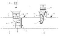
도 1 내지 도 9에서 도시한 바와 같이, 한 실시예의 배관 차단 장치(1)는 하우징(10), 배출 유닛(20), 그리고 유체 차단 유닛(30)을 포함한다.As shown in FIGS. 1 to 9, the
하우징(10)은 일반적으로 피팅(fitting)이라고 불리우며, 수리 및 교체하고 자 하는 배관(2)의 양쪽 외주면에 각각 장착된다. 하우징(10)은 제1 부재(11)와 제2 부재(12), 그리고 관통 부재(13)를 포함하고 있다. 제1 부재(11)는 배관(2)의 상부를 감싼다. 제1 부재(11)의 상부에는 배관(2)에 형성되는 제1 구멍(15)과 연통하는 개구부(14)가 형성되어 있다. 제2 부재(12)는 배관(2)의 하부를 감싸고, 제1 부재(11)와 체결된다. 이때 도시된 바와 같이 제1 부재(11)와 제2 부재(12)는 볼트 결합되어 체결될 수 있으나, 용접 작업하여 결합될 수도 있다. 관통 부재(13)는 제1 부재(11)의 개구부(14)와 연결되어 있으며 관통 부재(13)를 통해 플러깅 머신(도시되어 있지 않음), 태핑 머신(41) 및 배관 차단 유닛(30)을 배관(2) 내부로 삽입할 수 있다.The
배관(2)의 제1 구멍(15)은 제1 부재(11)와 제2 부재(12)를 체결한 후 관통 부재(13)를 통해 가이드되는 태핑 머신(41)을 이용하여 천공한다. 이때, 관통 부재(13)는 샌드위치 밸브(42)가 연결될 수 있다. 샌드위치 밸브(42)는 태핑 머신(41)이 제1 구멍(15)을 천공한 후 철거될 때 유체가 제1 구멍(15)을 통해 유출되는 것을 방지해 준다.The
배출 유닛(20)은 하우징(10)의 일측, 즉 수리하고자 하는 배관(2) 방향으로 펼쳐진 하우징(10) 부위에 설치된다. 이에 따라 한 실시예에 따른 배출 유닛(20)은 종래처럼 하우징(10)을 교체하고자 하는 배관 양쪽에 설치한 후, 따로 배관(2)에 배출 유닛(20)을 연결시키지 않아도 된다.The
배출 유닛(20)은 유체 차단 유닛(30)에 의해 차단된 배관(2) 내부의 유체를 외부로 배출시켜 주는 역할을 한다. 또한, 배출 유닛(20)은 연결 와이어(4)를 이용 하여 샌드위치 밸브(42)와 연결된 태핑 머신(41) 내부와 연결됨으로써 유체가 흐르는 배관(2)의 압력과 태핑 머신(41) 내부의 압력을 동일하게 맞추어 줄 수 있다. 압력을 동일하게 맞추어 줌으로써 작업자는 보다 안전하고 원활하게 보수 및 교체 작업할 수 있다.The
배출 유닛(20)의 구성은 크게 하우징 고정 부재(21)와 배출 몸체(22), 그리고 캡 부재(23)를 포함하고 있다. 또한, 배출 유닛(20)에는 패킹, 제1 압력 지지 부재(25), 제2 압력 지지 부재(26), 가스켓(27), 제3 압력 지지 부재(28) 및 오 링(29)을 더 포함한다.The configuration of the
하우징 고정 부재(21)는 하우징(10) 일측에 고정되고 배관(2)에 형성된 제2 구멍(16)과 연통된다. 이때 제2 구멍(16)은 제1 구멍(15)과 마찬가지로 태핑 머신(41)을 이용하여 천공한다. 이때, 천공되는 크기는 작업자가 임의적으로 조절하여 천공하면 된다.The
하우징 고정 부재(21)의 하부는 하우징(10) 일측에 형성된 홀(도시되어 있지 않음)에 삽입되어 결합된다. 이때, 하우징 고정 부재(21)는 홀에 삽입되고 용접 연결될 수 있으며, 나사 결합 등 다양한 방식을 이용하여 결합될 수도 있다. 하우징(10)에 형성된 홀은 하우징(10) 제조 당시에 형성되거나 하우징 고정 부재(21)를 연결한 후 태핑 머신(41)을 이용하여 제2 구멍(16)과 함께 천공할 수 있다.The lower portion of the
배출 몸체(22)는 그 내부에 배출 통로(22a)가 형성되어 있으며, 하우징 고정 부재(21)의 상단에 장착된다. 장착되는 방식은 하우징 고정 부재(21)의 상부 내주면에 제1 암나사부(21b)가 형성되고 배출 몸체(22)의 하부 외주면에는 제1 암나 사부(21b)와 체결되는 제1 숫나사부(22b)가 형성되어 서로 나사 결합한다. 나사 결합할 때 배출 몸체(22)에는 오 링(29, O-ring)이 배치되어 있다. 오 링(29)은 생략될 수 있으나 배치되어 있을 경우 배출 몸체(22)와 하우징 고정 부재(21)가 나사 결합할 시 서로간의 기밀성을 높여 주어 유체의 유출을 보다 효과적으로 막아 주는 역할을 해 준다.The
또한, 배출 몸체(22)와 하우징 고정 부재(21) 사이에는 제1 압력 지지 부재(25)와 패킹부(24)가 각각 배치되어 있다. 제1 압력 지지 부재(25)와 패킹부(24)는 하우징 고정 부재(21) 내부에 수용된다.In addition, a first
패킹부(24)는 말 그대로 하우징 고정 부재(21)와 배출 몸체(22) 사이에서 유체가 유출되는 것을 방지해 주는 역할을 해 주며, 제1 압력 지지 부재(25)는 배출 몸체(22)에 가해지는 유체의 압력을 고루 분산시켜 보다 효율적으로 지지해 주는 역할을 해 준다.The packing
또한, 제2 압력 지지 부재(26)도 제1 압력 지지 부재(25)와 마찬가지로 배출 몸체(22)에 가해지는 압력을 지지해 주는 역할을 해 준다. 제2 압력 지지 부재(26)는 배출 몸체(22)의 배출 통로(22a)에 장착되는데, 제2 압력 지지 부재(26)의 하단 외주면에는 제3 숫나사부(26a)가 형성되어 있으며, 배출 통로(22)의 내주면에는 제3 암나사부(22d)가 형성되어 서로 나사 결합시킴으로써 배출 통로(22)에 제2 압력 지지 부재(26)가 장착된다.In addition, like the first
캡 부재(23)는 배출 몸체(22)의 상단에 장착되어 배출 통로(22a)를 차단해 주는 역할을 한다. 추후에 유체를 배출하거나 연결 와이어(40)을 연결할 때는 캡 부재(23)를 제거하면 된다. 배출 몸체(22)의 상단 외주면에는 제2 숫나사부(22c)가 형성되어 있으며, 캡 부재(23)의 하단 내주면에는 제2 암나사부(23a)가 형성되어 서로 나사 결합함으로써 캡 부재(23)는 배출 몸체(22)의 상단에 장착된다.
또한, 하우징 고정 부재(21)의 상단 외주면과 나사 결합되어 배출 유닛(20)에 가해지는 유체의 압력을 지지해 주는 제3 압력 지지 부재(28)가 있다.In addition, there is a third
제3 압력 지지 부재(28)에는 제4 암나사부(28a)가 형성되어 하우징 고정 부재(21)의 상단 외주면에 형성된 제4 숫나사부(21a)에 나사 결합한다.A fourth female screw portion 28a is formed in the third
정리하자면, 배출 유닛(20)은 크게 하우징(10)에 연결되는 하우징 고정 부재(21), 하우징 고정 부재(21)에 연결되어 유체를 배출시켜 주는 배출 몸체(22), 그리고 배출 몸체(22)의 배출 통로(22a)를 차단시켜 주는 캡 부재(23)를 포함한다. 이때, 하우징 고정 부재(21)와 배출 몸체(23) 사이에는 패킹부(24)와 제1 압력 지지 부재(25)가, 배출 몸체(22) 내부에는 제2 압력 지지 부재(26)가, 하우징 고정 부재(21)와 연결되는 제3 압력 지지 부재(28) 및 가스켓(27)이 각각 배치되어 배출 유닛(20)에 가해지는 유체의 압력을 분배하여 각각 지지해 준다. 배출 유닛(20)의 구성 요소 중 하우징 고정 부재(21), 배출 몸체(22), 캡 부재(23)를 제외한 다른 구성 요소들은 생략될 수 있다.In summary, the discharging
이렇게 구성된 배출 유닛(20)은 하우징(10)의 일측에 연결되어 있음으로 보다 효율적으로 배관(2)의 보수 및 교체 작업을 할 수 있는 장점이 있다.The
유체 차단 유닛(30)은 크게 차단 부재(31), 이송 부재(32), 동력부(33)를 포함하고 있다.The
차단 부재(31)는 이송 부재(21)에 의해 가이드되어 배관(2) 내부에 삽입되어 배관(2)의 흐르는 유체를 차단시켜 준다. 이때 이송 부재(32)는 동력부(33)에 전달되는 동력에 의해 차단 부재(31)를 배관(2) 또는 관통 부재(13)로 이동시켜 준다.The blocking
차단 부재(31)에 대해 보다 자세히 설명하자면, 도시된 바와 같이 고정판(34)과 가변판(35), 그리고 차단막(36)을 포함하고 있다. 고정판(34)의 경우 이송 부재(32)와 연결되어 있으며, 가변판(35)은 고정판(34)의 양 측면에 각각 힌지 연결되어 있다.In detail, the blocking
고정판(34)과 가변판(35)의 정면에는 고무 재질로 이루어진 차단막(36)이 연결되어 있다. 차단막(36) 정면에는 보강판(37)이 장착되어 차단막(36)을 보호한다. 차단막(36)은 고무 재질의 특성상 밀폐성과 신축성, 그리고 밀착성을 동시에 가져 유체를 차단시키는데 효과적이다.A blocking
가변판(35)은 고정판(34)에 힌지 결합됨으로 소정 각도로 기울어질 수 잇다. 이에 접힐 수 있으므로, 제1 구멍(15)을 천공할 때 제1 구멍(15)을 보다 작게 천공할 수 있다. 가변판(35)의 경우 접히는 것을 원활하게 하게 위해 이송 부재(32)와 연결될 때 고정판(34)과 다르게 실린더 방식을 이용한 실린더 부재(38)를 이용하여 연결함으로써 이동될 때나 배관을 차단할 때 보다 원활하게 접히거나 펴질 수 있게 한다.The
실린더 부재(38)는 한쪽 끝이 가변판(35)와 연결되는 제1 부재, 한쪽 끝이 이송 부재(32)와 연결되는 제2 부재, 그리고 일측 내부로 제1 부재의 다른 쪽 끝이 삽입되어 있고, 타측 내부로 제2 부재의 다른 쪽 끝이 삽입되어 있는 연결부를 가진다. 제1 부재와 제2 부재는 이송 부재(32) 및 가변판(35) 사이에서 왕복 운동을 한다. 이때, 제1 부재(41)와 제2 부재(42)는 연결부(43) 내에서 떨어지거나 접촉한다. 연결부에서 제1 부재와 제2 부재가 서로 밀착될 때는, 가변판(35)이 배관(2) 내에서 펼쳐질 때이며, 연결부에서 제1 부재와 제2 부재가 떨어질 때는 가변부(35)가 배관(2) 내에서 접힐 때이다. 제1 부재(41)와 제2 부재(42)가 밀착 및 떨어짐으로써, 보다 원활하게 가변판(35)가 펴지거나 접힌다.The
즉, 차단 부재(31)는 가변판(35)이 접힌 상태로 제1 구멍(15)을 통과한 후 배관(2) 내부에 들어가게 된다. 배관(2) 하부에 차단 부재(31)의 하부가 닿게 되면 고정판(34)은 이송 유닛(32)을 기준으로 자연스럽게 앞으로 전진된다. 이때, 가변판(35)은 실린더 부재(38)에 의해 펴지게 된다. 이에 따라 유체는 차단된다.That is, the blocking
이렇게 유체를 차단되면, 차단된 부위에 유출 배출 구멍을 천공시켜 차단된 부위의 유체를 배출시킨 후, 배관을 교체 및 보수한다.When the fluid is blocked in this way, the outflow discharge hole is drilled in the blocked portion to discharge the fluid in the blocked portion, and then the pipe is replaced and repaired.
이상에서 설명한 본 발명은 전술한 실시예 및 첨부된 도면에 의해 한정되는 것은 아니고, 본 발명의 기술적 사상을 벗어나지 않는 범위 내에서 여러 가지 치환, 변형 및 변경이 가능함은 본 발명이 속하는 기술분야에서 통상의 지식을 가진 자에게 있어서 명백할 것이다.The present invention described above is not limited to the above-described embodiment and the accompanying drawings, and various substitutions, modifications, and changes are possible within the scope without departing from the technical spirit of the present invention. It will be evident to those who have knowledge of.
도 1은 본 발명의 한 실시예에 따른 배관 차단 장치의 사시도이다.1 is a perspective view of a pipe blocking device according to an embodiment of the present invention.
도 2는 본 발명의 한 실시예에 따른 하우징의 정면도이다.2 is a front view of a housing according to an embodiment of the present invention.
도 3은 본 발명의 한 실시예에 따른 하우징의 측면도이다.3 is a side view of a housing according to an embodiment of the present invention.
도 4는 본 발명의 한 실시예에 따른 배출 유닛을 설명하기 위한 분해도이다.Figure 4 is an exploded view for explaining the discharge unit according to an embodiment of the present invention.
도 5는 본 발명의 한 실시예에 따른 배출 유닛을 설명하기 위한 결합도이다.5 is a combined view for explaining the discharge unit according to an embodiment of the present invention.
도 6 내지 도 8은 본 발명의 한 실시예에 따른 유체 차단 유닛을 설명하기 위한 도면이다.6 to 8 are views for explaining a fluid blocking unit according to an embodiment of the present invention.
도 9는 본 발명의 한 실시예에 따른 배출 유닛이 연결 와이어에 연결된 도면이다.9 is a view of a discharge unit connected to a connecting wire according to an embodiment of the present invention.
* 도면의 주요부분에 대한 부호의 설명 *Explanation of symbols on the main parts of the drawings
1 : 배출 차단 장치 2 : 배관1: exhaust blocker 2: piping
10 : 하우징 11 : 제1 부재10
12 : 제2 부재 13 : 관통 부재12: second member 13: penetrating member
14 : 개구부 15 : 제1 구멍14 opening 15 a first hole
16 : 제2 구멍16: second hole
20 : 배출 유닛 21 : 하우징 고정 부재20: discharge unit 21: housing fixing member
21a : 제4 숫나사부 22b : 제1 암나사부21a: 4th
22 : 배출 몸체 22a : 배출 통로22:
22b : 제1 숫나사부 22c : 제2 숫나사부22b: 1st
22d : 제3 암나사부 23 : 캡 부재22d: 3rd female thread part 23: cap member
23a : 제2 암나사부 24 : 패킹23a: 2nd female thread part 24: packing
25 : 제1 압력 지지 부재 26 : 제2 압력 지지 부재25: first pressure support member 26: second pressure support member
26a : 제3 숫나사부 27 : 가스켓26a: third male thread 27: gasket
28 : 제3 압력 지지 부재 28a : 제4 암나사부28: 3rd pressure support member 28a: 4th female thread part
29 : 오 링(O-ring)29 O-ring
30 : 유체 차단 유닛 31 : 차단 부재30: fluid blocking unit 31: blocking member
32 : 이송 부재 33 : 동력부32: transfer member 33: power unit
34 : 고정판 35 : 가변판34: fixed plate 35: variable plate
36 : 차단막 37 : 보강판36: blocking film 37: reinforcement plate
38 : 실린더 부재38: cylinder member
40 : 연결 와이어 41 : 태핑 머신40: connection wire 41: tapping machine
42 : 샌드위치 밸브42: sandwich valve
Claims (16)
Translated fromKoreanPriority Applications (1)
| Application Number | Priority Date | Filing Date | Title |
|---|---|---|---|
| KR1020090102481AKR101085573B1 (en) | 2009-10-27 | 2009-10-27 | Exhaust blocker |
Applications Claiming Priority (1)
| Application Number | Priority Date | Filing Date | Title |
|---|---|---|---|
| KR1020090102481AKR101085573B1 (en) | 2009-10-27 | 2009-10-27 | Exhaust blocker |
Publications (2)
| Publication Number | Publication Date |
|---|---|
| KR20110045782A KR20110045782A (en) | 2011-05-04 |
| KR101085573B1true KR101085573B1 (en) | 2011-11-25 |
Family
ID=44240784
Family Applications (1)
| Application Number | Title | Priority Date | Filing Date |
|---|---|---|---|
| KR1020090102481AExpired - Fee RelatedKR101085573B1 (en) | 2009-10-27 | 2009-10-27 | Exhaust blocker |
Country Status (1)
| Country | Link |
|---|---|
| KR (1) | KR101085573B1 (en) |
Cited By (1)
| Publication number | Priority date | Publication date | Assignee | Title |
|---|---|---|---|---|
| KR101972703B1 (en) | 2018-09-12 | 2019-04-25 | 동명대학교산학협력단 | Fluid flow blocking device for pipe repair |
Families Citing this family (1)
| Publication number | Priority date | Publication date | Assignee | Title |
|---|---|---|---|---|
| CN109620449B (en)* | 2018-12-28 | 2021-02-05 | 江苏盛泽医院 | Visual disposable brush stick for oral care of critically ill patients |
Citations (1)
| Publication number | Priority date | Publication date | Assignee | Title |
|---|---|---|---|---|
| KR100799480B1 (en)* | 2002-12-02 | 2008-01-31 | 조희남 | Ordering device and method for water pipe repair |
- 2009
- 2009-10-27KRKR1020090102481Apatent/KR101085573B1/ennot_activeExpired - Fee Related
Patent Citations (1)
| Publication number | Priority date | Publication date | Assignee | Title |
|---|---|---|---|---|
| KR100799480B1 (en)* | 2002-12-02 | 2008-01-31 | 조희남 | Ordering device and method for water pipe repair |
Cited By (1)
| Publication number | Priority date | Publication date | Assignee | Title |
|---|---|---|---|---|
| KR101972703B1 (en) | 2018-09-12 | 2019-04-25 | 동명대학교산학협력단 | Fluid flow blocking device for pipe repair |
Also Published As
| Publication number | Publication date |
|---|---|
| KR20110045782A (en) | 2011-05-04 |
Similar Documents
| Publication | Publication Date | Title |
|---|---|---|
| KR101060729B1 (en) | Double plugging head for pipe blocking | |
| CN102803744A (en) | Methods and apparatus to charge accumulator apparatus | |
| CN104563224B (en) | Sanitary water faucet | |
| KR101085573B1 (en) | Exhaust blocker | |
| MX2007010263A (en) | Automatic draining double check vacuum breaker. | |
| KR101613358B1 (en) | A device for preventing a leakage of water without suspension of water supply | |
| RU2407939C2 (en) | Universal case of valve | |
| KR200399091Y1 (en) | Fitting for intercepting fluid flow in the pipe | |
| JP3682031B2 (en) | Piping branch valve device and branching method thereof | |
| KR100930817B1 (en) | Cleaning module for using pig cleaner | |
| KR20190120631A (en) | Fluid blocking apparatus | |
| RU2149736C1 (en) | Apparatus for cutting out opening in pressurized pipeline | |
| KR101112623B1 (en) | constructing structure and constructing method of tap water gauge | |
| RU2434178C2 (en) | Procedure and device for inset into pipeline equipped with seat-like head for branch line | |
| WO2005066535A1 (en) | Fluid coupling and coupling-unitized type integration unit | |
| KR200403467Y1 (en) | Valve device of city water meter | |
| CN102234025B (en) | Conveying pipeline switch | |
| KR100943937B1 (en) | Impurity Removal Device in Water Supply Pipe | |
| KR101613360B1 (en) | A fluid supply deformed fittings for bypass of fluid and the construction method for repairing the fluid conduit using the same | |
| KR102758782B1 (en) | Soundness test device between cylinder and spool of pumped storage power generation inlet valve | |
| KR101029526B1 (en) | Branch tee device for fluid shutoff | |
| KR101765888B1 (en) | Connector for v-type pipe | |
| KR100982693B1 (en) | Water intake apparatus | |
| KR101384864B1 (en) | High pressure valve | |
| CN211449947U (en) | Hydraulic engineering's pipeline |
Legal Events
| Date | Code | Title | Description |
|---|---|---|---|
| A201 | Request for examination | ||
| PA0109 | Patent application | St.27 status event code:A-0-1-A10-A12-nap-PA0109 | |
| PA0201 | Request for examination | St.27 status event code:A-1-2-D10-D11-exm-PA0201 | |
| R18-X000 | Changes to party contact information recorded | St.27 status event code:A-3-3-R10-R18-oth-X000 | |
| PG1501 | Laying open of application | St.27 status event code:A-1-1-Q10-Q12-nap-PG1501 | |
| D13-X000 | Search requested | St.27 status event code:A-1-2-D10-D13-srh-X000 | |
| D14-X000 | Search report completed | St.27 status event code:A-1-2-D10-D14-srh-X000 | |
| PE0902 | Notice of grounds for rejection | St.27 status event code:A-1-2-D10-D21-exm-PE0902 | |
| E13-X000 | Pre-grant limitation requested | St.27 status event code:A-2-3-E10-E13-lim-X000 | |
| P11-X000 | Amendment of application requested | St.27 status event code:A-2-2-P10-P11-nap-X000 | |
| P13-X000 | Application amended | St.27 status event code:A-2-2-P10-P13-nap-X000 | |
| E701 | Decision to grant or registration of patent right | ||
| PE0701 | Decision of registration | St.27 status event code:A-1-2-D10-D22-exm-PE0701 | |
| GRNT | Written decision to grant | ||
| PR0701 | Registration of establishment | St.27 status event code:A-2-4-F10-F11-exm-PR0701 | |
| PR1002 | Payment of registration fee | St.27 status event code:A-2-2-U10-U11-oth-PR1002 Fee payment year number:1 | |
| PG1601 | Publication of registration | St.27 status event code:A-4-4-Q10-Q13-nap-PG1601 | |
| LAPS | Lapse due to unpaid annual fee | ||
| PC1903 | Unpaid annual fee | St.27 status event code:A-4-4-U10-U13-oth-PC1903 Not in force date:20141116 Payment event data comment text:Termination Category : DEFAULT_OF_REGISTRATION_FEE | |
| PC1903 | Unpaid annual fee | St.27 status event code:N-4-6-H10-H13-oth-PC1903 Ip right cessation event data comment text:Termination Category : DEFAULT_OF_REGISTRATION_FEE Not in force date:20141116 | |
| PN2301 | Change of applicant | St.27 status event code:A-5-5-R10-R13-asn-PN2301 St.27 status event code:A-5-5-R10-R11-asn-PN2301 | |
| R18-X000 | Changes to party contact information recorded | St.27 status event code:A-5-5-R10-R18-oth-X000 | |
| P22-X000 | Classification modified | St.27 status event code:A-4-4-P10-P22-nap-X000 | |
| R18-X000 | Changes to party contact information recorded | St.27 status event code:A-5-5-R10-R18-oth-X000 | |
| R18-X000 | Changes to party contact information recorded | St.27 status event code:A-5-5-R10-R18-oth-X000 | |
| R18-X000 | Changes to party contact information recorded | St.27 status event code:A-5-5-R10-R18-oth-X000 |