KR101085328B1 - Laser irradiation method and device - Google Patents
Laser irradiation method and deviceDownload PDFInfo
- Publication number
- KR101085328B1 KR101085328B1KR1020070066830AKR20070066830AKR101085328B1KR 101085328 B1KR101085328 B1KR 101085328B1KR 1020070066830 AKR1020070066830 AKR 1020070066830AKR 20070066830 AKR20070066830 AKR 20070066830AKR 101085328 B1KR101085328 B1KR 101085328B1
- Authority
- KR
- South Korea
- Prior art keywords
- laser
- band
- irradiation area
- laser light
- shaped
- Prior art date
- Legal status (The legal status is an assumption and is not a legal conclusion. Google has not performed a legal analysis and makes no representation as to the accuracy of the status listed.)
- Active
Links
Images


Classifications
- H—ELECTRICITY
- H01—ELECTRIC ELEMENTS
- H01L—SEMICONDUCTOR DEVICES NOT COVERED BY CLASS H10
- H01L21/00—Processes or apparatus adapted for the manufacture or treatment of semiconductor or solid state devices or of parts thereof
- H01L21/02—Manufacture or treatment of semiconductor devices or of parts thereof
- H01L21/04—Manufacture or treatment of semiconductor devices or of parts thereof the devices having potential barriers, e.g. a PN junction, depletion layer or carrier concentration layer
- H01L21/18—Manufacture or treatment of semiconductor devices or of parts thereof the devices having potential barriers, e.g. a PN junction, depletion layer or carrier concentration layer the devices having semiconductor bodies comprising elements of Group IV of the Periodic Table or AIIIBV compounds with or without impurities, e.g. doping materials
- H01L21/26—Bombardment with radiation
- H01L21/263—Bombardment with radiation with high-energy radiation
- H01L21/268—Bombardment with radiation with high-energy radiation using electromagnetic radiation, e.g. laser radiation
- B—PERFORMING OPERATIONS; TRANSPORTING
- B23—MACHINE TOOLS; METAL-WORKING NOT OTHERWISE PROVIDED FOR
- B23K—SOLDERING OR UNSOLDERING; WELDING; CLADDING OR PLATING BY SOLDERING OR WELDING; CUTTING BY APPLYING HEAT LOCALLY, e.g. FLAME CUTTING; WORKING BY LASER BEAM
- B23K26/00—Working by laser beam, e.g. welding, cutting or boring
- B23K26/02—Positioning or observing the workpiece, e.g. with respect to the point of impact; Aligning, aiming or focusing the laser beam
- B23K26/06—Shaping the laser beam, e.g. by masks or multi-focusing
- B23K26/062—Shaping the laser beam, e.g. by masks or multi-focusing by direct control of the laser beam
- B23K26/0622—Shaping the laser beam, e.g. by masks or multi-focusing by direct control of the laser beam by shaping pulses
- B—PERFORMING OPERATIONS; TRANSPORTING
- B23—MACHINE TOOLS; METAL-WORKING NOT OTHERWISE PROVIDED FOR
- B23K—SOLDERING OR UNSOLDERING; WELDING; CLADDING OR PLATING BY SOLDERING OR WELDING; CUTTING BY APPLYING HEAT LOCALLY, e.g. FLAME CUTTING; WORKING BY LASER BEAM
- B23K26/00—Working by laser beam, e.g. welding, cutting or boring
- B23K26/08—Devices involving relative movement between laser beam and workpiece
Landscapes
- Physics & Mathematics (AREA)
- Optics & Photonics (AREA)
- Engineering & Computer Science (AREA)
- High Energy & Nuclear Physics (AREA)
- Plasma & Fusion (AREA)
- Mechanical Engineering (AREA)
- Toxicology (AREA)
- Health & Medical Sciences (AREA)
- Electromagnetism (AREA)
- Condensed Matter Physics & Semiconductors (AREA)
- General Physics & Mathematics (AREA)
- Manufacturing & Machinery (AREA)
- Computer Hardware Design (AREA)
- Microelectronics & Electronic Packaging (AREA)
- Power Engineering (AREA)
- Laser Beam Processing (AREA)
- Lasers (AREA)
- Recrystallisation Techniques (AREA)
Abstract
Translated fromKoreanDescription
Translated fromKorean도 1은, 실시예 1에 관한 레이저조사장치의 구성설명도이다.1 is a diagram illustrating the configuration of a laser irradiation apparatus according to the first embodiment.
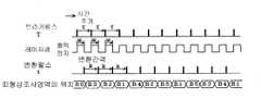
도 2는, 실시예 1에 관한 레이저조사장치의 동작을 도시하는 타이밍차트이다.2 is a timing chart showing the operation of the laser irradiation apparatus according to the first embodiment.
도 3은, 실시예 2에 관한 레이저조사장치의 구성설명도이다.3 is a diagram for explaining the configuration of a laser irradiation apparatus according to a second embodiment.
도 4는, 실시예 2에 관한 레이저조사장치의 동작을 도시하는 타이밍차트이다.4 is a timing chart showing the operation of the laser irradiation apparatus according to the second embodiment.
※ 부호의 설명 ※※ Explanation of code ※
1…레이저발진기2…AOD소자One…
3…호모디나이저 광학계4…p-렌즈3 ... Homogenizer optical system 4... p-lens
5…이동대6…띠형상조사영역5... Mobile table 6.. Band-shaped irradiation area
7…레이저발진 트리거 펄스 발생기8…변환타이밍 제어회로7 ... Laser oscillation trigger pulse generator 8.. Conversion timing control circuit
91~95…AOD소자 구동펄스 발생기100, 200…레이저조사장치91 to 95. AOD element
본 발명은 레이저조사방법 및 장치에 관한 것이며, 더 상세하게는 레이저 조사후의 피처리기판에 줄무늬와 같은 처리패턴이 나타나지 않도록 레이저조사하는 것이 가능한 레이저조사방법 및 장치에 관한 것이다.The present invention relates to a laser irradiation method and apparatus, and more particularly, to a laser irradiation method and apparatus that can be irradiated with a laser so that the processing pattern such as stripes on the substrate to be processed after the laser irradiation does not appear.
종래의 띠형상조사영역을 가지는 광선빔을 피처리기판에 조사할 때에 띠형상조사영역의 단축방향으로 광선빔을 주사(走査)적으로 이동하는 동시에 띠형상조사영역의 장축방향으로 띠형상조사영역을 진동시키는 반도체장치의 제조방법이 알려져 있다(예를 들면, 특허문헌 1 참조).When irradiating a substrate with a light beam having a conventional band-shaped irradiation area onto the substrate to be processed, the beam beam is scanned in the short axis direction of the band-shaped area, and the band-shaped area in the long axis direction of the band-shaped area. BACKGROUND OF THE INVENTION A manufacturing method of a semiconductor device for vibrating a battery is known (see
[특허문헌 1] 일본국 특공 평 04-10216호 공보[Patent Document 1] Japanese Patent Application Laid-Open No. 04-10216
상기 종래기술에서는 띠형상조사영역을 장축방향으로 일정주파수(예컨대, 1kHz)로 진동시키고 있기 때문에, 띠형상조사영역의 장축방향으로 띠형상조사영역의 위치를 변화시키고 있다고는 해도 그 변화가 규칙적으로 된다.In the prior art, since the band-shaped irradiation area is vibrated at a constant frequency (for example, 1 kHz) in the major axis direction, even if the position of the band-shaped irradiation area is changed in the major axis direction of the band-shaped area, the change is regular. do.
그러나, 띠형상조사영역의 장축방향의 위치변화가 규칙적이 되면, 처리후의 피처리기판에 줄무늬와 같은 처리패턴이 나타나고, 심한 경우에는 시인할 수 있을 정도의 줄무늬가 나타나 버리는 문제점이 있다.However, when the positional change in the major axis direction of the band-shaped irradiation area becomes regular, there is a problem that a processing pattern such as a stripe appears on the substrate to be processed after treatment, and in a severe case, a stripe that can be visually recognized appears.
그래서, 본 발명의 목적은 레이저조사후의 피처리기판에 줄무늬와 같은 처리패턴이 나타나지 않도록 레이저조사하는 것이 가능한 레이저조사방법 및 장치를 제공하는 것에 있다.It is therefore an object of the present invention to provide a laser irradiation method and apparatus capable of laser irradiation such that a processing pattern such as streaks does not appear on a substrate to be processed after laser irradiation.
제1의 관점에서는, 본 발명은 반도체기판(S)상에 띠형상조사영역(6)을 형성하여 레이저광을 조사하고, 띠형상조사영역(6)의 장축방향으로 띠형상조사영역(6)의 위치를 변경하면서 띠형상조사영역(6)의 단축방향으로 반도체기판(S)을 이동하는 레이저조사방법으로서, 띠형상조사영역(6)의 장축방향의 위치를 변경하는 타이밍을 불규칙적으로 하는 것을 특징으로 하는 레이저조사방법을 제공한다.In the first aspect, the present invention forms a band-
상기 제1의 관점에 의한 레이저조사방법에서는, 레이저광의 띠형상조사영역(6)의 장축방향으로 띠형상조사영역(6)의 위치를 변경하면서 레이저조사를 실행하지만, 그 위치를 불규칙적으로 변경하거나, 또는 위치는 여러 개소의 고정위치로 하지만, 위치를 변경하는 타이밍을 불규칙적으로 변경하거나, 또는 위치를 불규칙적으로 변경하는 동시에 위치를 변경하는 타이밍도 불규칙적으로 변경한다. 이와 같이 위치를 변경하는 타이밍을 불규칙적으로 함으로써 레이저조사 후의 피처리기판에 줄무늬와 같은 처리패턴이 나타나지 않게 된다.In the laser irradiation method according to the first aspect, laser irradiation is performed while changing the position of the band-
제2의 관점에서는, 본 발명은 상기 제1의 관점에 의한 레이저조사방법에서, 상기 띠형상조사영역(6)의 위치를 2개소 이상으로 하고, 이들 위치중 하나를 차례대로 선택하는 것으로 하며, 선택하는 타이밍을 랜덤으로 한 것을 특징으로 하는 레이저조사방법을 제공한다.In the second aspect, the present invention is a laser irradiation method according to the first aspect, wherein the band-
상기 제2의 관점에 의한 레이저조사방법에서는, 레이저광의 띠형상조사영역(6)의 장축방향으로 띠형상조사영역(6)의 위치를 변경하면서 레이저 조사를 실행하지만, 위치는 여러 개소의 고정위치로 하지만 위치를 변경하는 타이밍을 불규칙 적으로 변경한다. 이에 따라 레이저조사 후의 피처리기판에 줄무늬와 같은 처리패턴이 나타나지 않게 된다.In the laser irradiation method according to the second aspect, laser irradiation is performed while changing the position of the band-
제3의 관점에서는, 본 발명은 상기 제2의 관점에 의한 레이저조사방법에서, 상기 레이저광의 조사는 펄스형상으로 실행하고, 그 펄스간격의 1배에서 16배 사이에서 랜덤으로 선택한 간격으로 상기 띠형상조사영역(6)의 위치를 변경하는 것을 특징으로 하는 레이저조사방법을 제공한다.In a third aspect, the present invention provides a laser beam irradiation method according to the second aspect, wherein the laser beam is irradiated in a pulse shape, and the band is randomly selected between 1 and 16 times the pulse interval. There is provided a laser irradiation method characterized by changing the position of the shape irradiation area (6).
상기 제3의 관점에 의한 레이저조사방법에서는, 위치를 변경하는 타이밍을 실질적으로 불규칙적으로 하는 것이 가능하다.In the laser irradiation method according to the third aspect, the timing for changing the position can be made substantially irregular.
제4의 관점에서는, 본 발명은 상기 제1의 관점에 의한 레이저조사방법에 있어서, 상기 띠형상조사영역(6)의 위치는 5개소 이상으로 하고, 이들 위치중 하나를 랜덤으로 선택하는 것으로 하며, 선택하는 타이밍도 랜덤으로 한 것을 특징으로 하는 레이저조사방법을 제공한다.In a fourth aspect, the present invention is the laser irradiation method according to the first aspect, wherein the band-
상기 제4의 관점에 의한 레이저조사방법에서는 레이저광의 띠형상조사영역(6)의 장축방향으로 띠형상조사영역(6)의 위치를 변경하면서 레이저 조사를 실행하지만, 그 위치를 5개소 이상의 고정위치로 하는 것이, 이들 중의 어느 위치를 선택할지를 불규칙적으로 변경한다. 이에 따라 위치가 실질적으로 불규칙적이 되며, 레이저조사후의 피처리기판에 줄무늬와 같은 처리패턴이 나타나지 않게 된다.In the laser irradiation method according to the fourth aspect, the laser irradiation is performed while changing the position of the band-
제5의 관점에서는, 본 발명은 상기 제4의 관점에 의한 레이저조사방법에서, 상기 레이저광의 조사는 펄스형상으로 실행하는 것을 특징으로 하는 레이저조사방법을 제공한다.In a fifth aspect, the present invention provides a laser irradiation method, wherein in the laser irradiation method according to the fourth aspect, the irradiation of the laser light is performed in a pulse shape.
상기 제5의 관점에 의한 레이저조사방법에서는 위치를 변경하는 타이밍이 일정하므로 제어가 용이해진다.In the laser irradiation method according to the fifth aspect, the timing of changing the position is constant, so that the control becomes easy.
제6의 관점에서는, 본 발명은 상기 제5의 관점에 의한 레이저조사방법에서, 상기 레이저광의 조사는 펄스간격의 1배에서 16배 사이에서 랜덤으로 선택한 간격으로 상기 띠형상조사영역(6)의 위치를 변경하는 것을 특징으로 하는 레이저조사방법을 제공한다.In a sixth aspect, the present invention provides the laser irradiation method according to the fifth aspect, wherein the irradiation of the laser light is performed at randomly selected intervals between 1 and 16 times the pulse interval. It provides a laser irradiation method, characterized in that for changing the position.
상기 제6의 관점에 의한 레이저조사방법에서는, 위치를 변경하는 타이밍을 실질적으로 불규칙적으로 하는 것이 가능하다.In the laser irradiation method according to the sixth aspect, the timing for changing the position can be made substantially irregular.
제7의 관점에서는, 본 발명은 레이저광(A)을 출력하는 레이저발진기(1)와, 상기 레이저광(A)을 입출력하는 레이저광(B1, B2)의 위치를 2개소 이상으로 변경하기 위한 광학소자(2)와, 상기 레이저광(B1, B2)의 위치가 변하는 방향을 장축방향으로 하는 띠형상조사영역(6)에 상기 레이저광(B1, B2)을 정형하여 반도체기판(S)에 조사하는 광학계(3, 4)와, 상기 반도체기판(S)을 지지하여 상기 띠형상조사영역(6)의 단축방향으로 이동할 수 있는 이동대(5)와, 상기 레이저광(B1, B2)의 하나를 차례대로 선택하여 변환하기 위한 변환수단(10)과, 상기 변환을 위한 변환 타이밍을 랜덤으로 하는 변환타이밍 제어수단(8)을 구비한 것을 특징으로 하는 레이저조사장치(100)를 제공한다.In a seventh aspect, the present invention provides a method for changing the positions of the
상기 제7의 관점에 의한 레이저조사장치(100)에서는, 상기 제2의 관점에 의한 레이저조사방법을 적합하게 실시할 수 있다.In the
제8의 관점에서는, 본 발명은 상기 제7의 관점에 의한 레이저조사장치에서, 상기 레이저발진기(1)는 펄스형상으로 레이저광을 출력하고, 상기 변환타이밍 제어수단(8)은 상기 레이저광의 펄스간격의 1배에서 16배 사이에서 랜덤으로 선택한 간격을 상기 변환타이밍으로 하는 것을 특징으로 하는 레이저조사장치를 제공한다.In the eighth aspect, the present invention is the laser irradiation apparatus according to the seventh aspect, wherein the
상기 제8의 관점에 의한 레이저조사장치(100)에서는, 상기 제3의 관점에 의한 레이저조사방법을 적합하게 실시할 수 있다.In the
제9의 관점에서는, 본 발명은 레이저광(A)을 출력하는 레이저발진기(1)와, 레이저광(B1)을 입출력하는 레이저광(B1 ~ B5)의 위치를 5개소 이상으로 변경하기 위한 광학소자(2)와, 상기 레이저광(B1 ~ B5)의 위치가 변하는 방향을 장축방향으로 하는 띠형상조사영역(6)에 상기 레이저광(B1 ~ B5)을 정형하여 반도체기판(S)에 조사하는 광학계(3, 4)와, 상기 반도체기판(S)을 지지하여 상기 띠형상조사영역(6)의 단축방향으로 이동할 수 있는 이동대(5)와, 상기 레이저광(B1 ~ B5)의 하나를 랜덤으로 선택하여 변환하기 위한 변환수단(10)과, 상기 변환을 위한 변환 타이밍을 일정하게 또는 랜덤으로 하는 변환타이밍 제어수단(8)을 구비한 것을 특징으로 하는 레이저조사장치(20)를 제공한다.In the ninth aspect, the present invention provides an optical device for changing the positions of the
상기 제9의 관점에 의한 레이저조사장치(100)에서는 상기 제4의 관점에 의한 레이저조사방법을 적합하게 실시할 수 있다.In the
제10의 관점에서는, 본 발명은 상기 제9의 관점에 의한 레이저조사장치에 서, 상기 레이저발진기(1)는 펄스형상으로 레이저광을 출력하는 것을 특징으로 하는 레이저조사장치를 제공한다.In a tenth aspect, the present invention provides a laser irradiation apparatus according to the ninth aspect, wherein the laser oscillator (1) outputs laser light in a pulse shape.
상기 제10의 관점에 의한 레이저조사장치(100)에서는, 상기 제5의 관점에 의한 레이저조사방법을 적합하게 실시할 수 있다.In the
제11의 관점에서는, 본 발명은 상기 제10의 관점에 의한 레이저조사장치에 서, 상기 레이저발진기(1)는 펄스형상으로 레이저광을 출력하고, 상기 변환타이밍 제어수단(8)은 상기 레이저광의 펄스간격의 1배에서 16배의 사이에서 랜덤으로 선택한 간격을 상기 변환타이밍으로 하는 것을 특징으로 하는 레이저조사장치를 제공한다.In the eleventh aspect, the present invention provides a laser irradiation apparatus according to the tenth aspect, wherein the
상기 제11의 관점에 의한 레이저조사장치(100)에서는 상기 제6의 관점에 의한 레이저조사방법을 적합하게 실시할 수 있다.In the
제12의 관점에서는, 본 발명은 상기 제7에서 상기 제11 중 어느 하나의 관점에 의한 레이저조사장치에서, 상기 광학소자(2)는 음향광학편향기인 것을 특징으로 하는 레이저조사장치를 제공한다.In a twelfth aspect, the present invention provides a laser irradiation apparatus, wherein in the laser irradiation apparatus according to any one of the seventh to eleventh aspects, the
상기 제12의 관점에 의한 레이저조사장치(100)에서는, 광학소자(2)로서 음향광학편향기를 사용하기 때문에, 종래기술에서의 XY 스테이지에 상당하는 이동대(5) 또는 종래 기술에서의 카본·히터에 상당하는 레이저발진기(1)나 광학계(3)를 움직이는 경우에 비하여 고속으로 위치 제어할 수 있다.In the
본 발명의 레이저조사방법 및 장치에 의하면, 위치를 변경하는 타이밍을 불규칙적으로 함으로써, 레이저조사 후의 피처리기판에 줄무늬와 같은 처리패턴이 나타나지 않게 된다. 즉, 띠형상조사영역을 그 장축방향으로 규칙적으로 흔드는 것에 기인하는 조사 램을 억제하는 것이 가능하다.According to the laser irradiation method and apparatus of the present invention, the timing for changing the position is made irregular so that the processing pattern such as stripes does not appear on the substrate to be processed after laser irradiation. That is, it is possible to suppress the irradiation ram caused by regularly shaking the band-shaped irradiation area in the major axis direction.
이하, 도면에 도시하는 실시의 형태에 의하여 본 발명을 더욱 상세히 설명한다. 또한, 이것에 의해 본 발명이 한정되는 것은 아니다.EMBODIMENT OF THE INVENTION Hereinafter, this invention is demonstrated further in detail by embodiment shown to drawing. In addition, this invention is not limited by this.
[[실시예Example 1] One]
도 1은, 실시예 1에 관한 레이저조사장치(100)를 도시하는 구성설명도이다.FIG. 1: is a structural explanatory drawing which shows the
상기 레이저장치(100)는 트리거펄스(T)에 따라서 레이저광(A)을 펄스출력하는 레이저발진기(1)와, 입력된 레이저광(A)을 출력하는 방향을 변경하는 AOD소자(음향광학편향기)(2)와, AOD소자(2)로부터 출력된 레이저광(B1) 또는 (B2)의 위치가 변화하는 방향을 장축방향으로 하는 띠형상조사영역(6)에 레이저광(B1) 또는 (B2)을 정형하여 반도체기판(S)에 조사하기 위한 호모디나이저 광학계(3) 및 p-렌즈(4)와, 반도체기판(S)을 지지하여 띠형상조사영역(6)의 단축방향으로 이동할 수 있는 이동대(5)와, 예를 들면 250μs간격으로 트리거펄스(T)를 출력하는 레이저발진 트리거펄스발생기(7)와, 트리거펄스(T)의 펄스간격의 1배에서 16배 사이에서 랜덤으로 선택한 간격으로 변환펄스(t)를 출력하는 변환타이밍 제어회로(8)와, AOD소자(2)로부터 출력되는 레이저광을 레이저광(B1)의 방향으로 하기 위한 제1의 편향펄스(b1)를 출력하는 제1의 AOD소자 구동펄스발생기(91)와, AOD소자(2)로부터 출력되는 레이저광을 레이저광(B1)의 방향으로 하기 위한 제2의 편향펄스(b2)를 출력하는 제2의 AOD소자 구동펄스발생기(92)와, 변환펄스(t)에 따라서 제1의 편향펄스(b1)와 제2의 편향펄스(b2)를 교대로 변환하여 AOD소자(2)로 입력하는 변환회 로(10)를 구비하고 있다.The
도 2는, 트리거펄스(T)와, 레이저광의 출력기간과, 변환펄스(t)와, 띠형상조사영역(6)의 위치변화를 설명하는 타이밍차트이다.FIG. 2 is a timing chart illustrating the positional change of the trigger pulse T, the output period of the laser light, the conversion pulse t, and the band-shaped
트리거펄스(T)의 간격(τ)은 예를 들면 250μs로 일정하다.The interval τ of the trigger pulse T is constant at 250 μs, for example.
레이저광은 트리거펄스(T)에 동기하여, 예를 들면 펄스 폭 W=125μs이고, 펄스형상으로 출력된다.In synchronism with the trigger pulse T, the laser light has a pulse width of W = 125 mu s and is output in a pulse shape.
변환펄스(t)는 레이저광의 정지에 동기하여 출력된다. 변환펄스(t)의 간격(K)은 예컨대 250μs, 500μs, 750μs, …, 3750μs, 4000μs중 어느 하나가 랜덤으로 선택된다.The conversion pulse t is output in synchronization with the stop of the laser light. The interval K of the conversion pulse t is, for example, 250 µs, 500 µs, 750 µs,... Any one of 3750 μs and 4000 μs is randomly selected.
띠형상조사영역(6)의 위치는 서로 (B1) 또는 (B2)가 되지만, 변환하는 간격(K)이 실질적으로 불규칙적이라 할 수 있으므로, 위치(B1) 또는 (B2)에서 조사하는 시간이 불규칙적이 된다.The positions of the band-shaped
실시예 1의 레이저조사장치(100)에 의하면, 띠형상조사영역(6)의 장축방향으로 띠형상조사영역(6)의 위치를 변경하면서 레이저조사를 실행한다. 띠형상조사영역(6)의 위치는 (B1) 또는 (B2)의 2개소로 고정되어 있지만, 위치를 변환하는 타이밍을 불규칙적으로 변경한다. 이에 따라 레이저조사 후의 피처리기판(S)에 줄무늬와 같은 처리패턴이 나타나지 않게 된다. 또 위치변환을 AOD소자(2)를 사용하여 실행하므로, 고속으로 변경하는 것이 가능하다.According to the
또한, 상기 설명에서는 위치를 (B1)과 (B2)의 2개소로 고정되어 있으나, 위치를 3개소 이상으로 하고 차례대로 변경하도록 하여도 된다.In addition, in the above description, the position is fixed to two places (B1) and (B2), but the position may be changed to three or more places in order.
[[실시예Example 2] 2]
도 3은, 실시예 2에 관한 레이저조사장치(200)를 도시하는 구성설명도이다.3 is a configuration explanatory diagram showing a
상기 레이저조사장치(200)는 트리거펄스(T)에 따라서 레이저광(A)을 펄스출력하는 레이저발진기(1)와, 입력된 레이저광(A)을 출력하는 방향을 변경하는 AOD소자(음향광학편향기)(2)와, AOD소자(2)로부터 출력된 레이저광(B1) ~ (B5)의 위치가 변화하는 방향을 장축방향으로 하는 띠형상조사영역(6)에 레이저광(B1) ~ (B5)을 정형하여 반도체기판(S)에 조사하기 위한 호모디나이저광학계(3) 및 p-렌즈(4)와, 반도체기판(S)을 지지하여 띠형상조사영역(6)의 단축방향으로 이동할 수 있는 이동대(5)와, 예를들면 250μs 간격으로 트리거펄스(T)를 출력하는 레이저발진 트리거펄스발생기(7)와, 트리거펄스(T)의 펄스간격과 같은 간격(k)으로 변환펄스(t)를 출력하는 변환타이밍 제어회로(8)와, AOD소자(2)로부터 출력되는 레이저광을 레이저광(B1) ~ (B5)의 방향으로 하기 위한 제1 ~ 제5의 편향펄스(b1) ~ (b5)를 출력하는 제1 ~ 제5의 편향펄스(b1) ~ (b5)중 어느 하나를 랜덤으로 선택하여 AOD소자(2)로 입력하는 변환회로(10)를 구비하고 있다.The
도 4는, 트리거펄스(5)와, 레이저광의 출력기간과, 변환펄스(t)와, 띠형상조사영역(6)의 위치변화를 설명하는 타이밍차트이다.4 is a timing chart for explaining the position change of the
트리거펄스(T)의 간격(τ)은, 예를 들면 펄스폭 250μs로 일정하다.The interval τ of the trigger pulse T is constant at a pulse width of 250 μs, for example.
레이저광은, 트리거펄스(T)에 동기하여, 예를 들면 펄스폭 W=125μs이고, 펄스형상으로 출력된다.In synchronism with the trigger pulse T, the laser beam is pulse-width W = 125 s, and is output in a pulse shape.
변환펄스(t)는 레이저광의 정지에 동기하여 출력된다. 변환펄스(t)의 간 격(K)은 예를 들면, 250μs이다.The conversion pulse t is output in synchronization with the stop of the laser light. The interval K of the conversion pulse t is, for example, 250 µs.
띠형상조사영역(6)의 위치는 (B1) ~ (B5)중 어느 하나가 불규칙적으로 선택된다. 따라서, 각 조사위치(B1) ~ (B5)에서 조사하는 시간은 일정하게 되지만, 어느 위치에서 조사될지가 불규칙적으로 된다.In the position of the band-shaped
실시예 2의 레이저조사장치(200)에 의하면, 띠형상조사영역(6)의 장축방향으로 띠형상조사영역(6)의 영역을 변경하면서 레이저조사를 실행한다. 띠형상조사영역(6)의 위치는 (B1) ~ (B5)중 어느 하나가 되며, 각 위치에서의 조사시간은 일정해진다. 그러나, 어느 위치가 될지 불규칙적으로 되므로, 레이저조사 후의 피처리기판(S)에 줄무늬와 같은 처리패턴이 나타나지 않게 된다. 또 위치의 변환을 AOD소자(2)를 사용하여 실행하므로 고속으로 변환하는 것이 가능하다.According to the
[[실시예Example 3] 3]
실시예 2의 레이저조사장치(200)에서, 실시예 1의 변환타이밍 제어회로(8)를 사용해도 된다.In the
실시예 3의 레이저조사장치에 의하면, 띠형상조사영역(6)의 장축방향으로 띠형상조사영역(6)의 위치를 변경하면서 레이저조사를 실행한다. 띠형상조사영역(6)의 위치는 (B1) ~ (B5)중 어느 하나가 되지만, 어느 위치가 될지 불규칙적으로 된다. 또 각 위치에서의 조사시간도 불규칙적으로 된다. 따라서, 레이저조사 후의 피처리기판(S)에 줄무늬와 같은 처리패턴이 나타나지 않게 된다. 또 위치의 변환을 AOD소자(2)를 사용하여 실행하므로 고속으로 변환하는 것이 가능하다.According to the laser irradiation apparatus of the third embodiment, laser irradiation is performed while changing the position of the strip-shaped
본 발명의 레이저조사방법 및 장치는, 예를 들면, 반도체층의 제작이나 활성화처리에 이용할 수 있다.The laser irradiation method and apparatus of the present invention can be used, for example, in the fabrication or activation of a semiconductor layer.
본 발명의 레이저조사방법 및 장치에 의하면, 위치를 변경하는 타이밍을 불규칙적으로 함으로써, 레이저조사 후의 피처리기판에 줄무늬와 같은 처리패턴이 나타나지 않게 된다. 즉, 띠형상조사영역을 그 장축방향으로 규칙적으로 흔드는 것에 기인하는 조사 램을 억제하는 것이 가능하다.According to the laser irradiation method and apparatus of the present invention, the timing for changing the position is made irregular so that the processing pattern such as stripes does not appear on the substrate to be processed after laser irradiation. That is, it is possible to suppress the irradiation ram caused by regularly shaking the band-shaped irradiation area in the major axis direction.
Claims (12)
Translated fromKoreanApplications Claiming Priority (2)
| Application Number | Priority Date | Filing Date | Title |
|---|---|---|---|
| JP2006188744AJP4297923B2 (en) | 2006-07-10 | 2006-07-10 | Laser irradiation method and apparatus |
| JPJP-P-2006-00188744 | 2006-07-10 |
Publications (2)
| Publication Number | Publication Date |
|---|---|
| KR20080005853A KR20080005853A (en) | 2008-01-15 |
| KR101085328B1true KR101085328B1 (en) | 2011-11-23 |
Family
ID=39073459
Family Applications (1)
| Application Number | Title | Priority Date | Filing Date |
|---|---|---|---|
| KR1020070066830AActiveKR101085328B1 (en) | 2006-07-10 | 2007-07-04 | Laser irradiation method and device |
Country Status (3)
| Country | Link |
|---|---|
| JP (1) | JP4297923B2 (en) |
| KR (1) | KR101085328B1 (en) |
| TW (1) | TWI400747B (en) |
Families Citing this family (2)
| Publication number | Priority date | Publication date | Assignee | Title |
|---|---|---|---|---|
| US8337618B2 (en) | 2009-10-26 | 2012-12-25 | Samsung Display Co., Ltd. | Silicon crystallization system and silicon crystallization method using laser |
| JP5154595B2 (en)* | 2009-10-26 | 2013-02-27 | 三星ディスプレイ株式會社 | Silicon crystallization system and silicon crystallization method using laser |
Citations (1)
| Publication number | Priority date | Publication date | Assignee | Title |
|---|---|---|---|---|
| JP2004349415A (en)* | 2003-05-21 | 2004-12-09 | Hitachi Ltd | Active matrix substrate manufacturing method and image display apparatus using the same |
Family Cites Families (2)
| Publication number | Priority date | Publication date | Assignee | Title |
|---|---|---|---|---|
| US5858807A (en)* | 1996-01-17 | 1999-01-12 | Kabushiki Kaisha Toshiba | Method of manufacturing liquid crystal display device |
| US7935941B2 (en)* | 2004-06-18 | 2011-05-03 | Electro Scientific Industries, Inc. | Semiconductor structure processing using multiple laser beam spots spaced on-axis on non-adjacent structures |
- 2006
- 2006-07-10JPJP2006188744Apatent/JP4297923B2/enactiveActive
- 2007
- 2007-07-04KRKR1020070066830Apatent/KR101085328B1/enactiveActive
- 2007-07-06TWTW096124650Apatent/TWI400747B/enactive
Patent Citations (1)
| Publication number | Priority date | Publication date | Assignee | Title |
|---|---|---|---|---|
| JP2004349415A (en)* | 2003-05-21 | 2004-12-09 | Hitachi Ltd | Active matrix substrate manufacturing method and image display apparatus using the same |
Also Published As
| Publication number | Publication date |
|---|---|
| TWI400747B (en) | 2013-07-01 |
| TW200814159A (en) | 2008-03-16 |
| KR20080005853A (en) | 2008-01-15 |
| JP2008016745A (en) | 2008-01-24 |
| JP4297923B2 (en) | 2009-07-15 |
Similar Documents
| Publication | Publication Date | Title |
|---|---|---|
| US7521649B2 (en) | Laser processing apparatus and laser processing method | |
| CN107004780B (en) | Three-dimensional patterning method using laser | |
| JP4847435B2 (en) | Laser processing apparatus and laser processing method | |
| TWI481462B (en) | Laser processing device and laser processing method | |
| EP2011599A1 (en) | Laser processing method and laser processing apparatus | |
| JP6773822B2 (en) | Laser system and method for AOD laut processing | |
| KR20180122605A (en) | Laser processing equipment | |
| KR101085328B1 (en) | Laser irradiation method and device | |
| JP2008168297A (en) | Apparatus and method for laser beam machining | |
| JP5819149B2 (en) | Periodic structure creation method and periodic structure creation apparatus | |
| KR101897337B1 (en) | Method and device for laser machining a substrate with multiple deflections of a laser radiation | |
| KR102319782B1 (en) | Laser irradiation method and device | |
| WO2008148377A3 (en) | Method for the selective thermal treatment of the surface of a planar substrate | |
| JP5197271B2 (en) | Laser processing apparatus and laser processing method | |
| JP5920662B2 (en) | Laser processing apparatus and laser processing method | |
| JP5618373B2 (en) | Laser processing equipment for glass substrates | |
| JPWO2020251782A5 (en) | ||
| JP2009148812A (en) | Laser beam machining device and method | |
| JP2015089565A (en) | Laser irradiation method and apparatus | |
| CN113385806A (en) | Control device for laser processing device, and laser processing method | |
| KR102751606B1 (en) | Low Porosity apparatus of electrostatic chuck | |
| JPH10156560A (en) | Laser marking device and its method | |
| KR20130112109A (en) | Apparatus and method of controlling laser output pulse for laser processing uniformity | |
| JP3378243B1 (en) | Laser processing method | |
| KR20180055293A (en) | Apparatus and method of laser processing |
Legal Events
| Date | Code | Title | Description |
|---|---|---|---|
| PA0109 | Patent application | Patent event code:PA01091R01D Comment text:Patent Application Patent event date:20070704 | |
| PG1501 | Laying open of application | ||
| A201 | Request for examination | ||
| PA0201 | Request for examination | Patent event code:PA02012R01D Patent event date:20090929 Comment text:Request for Examination of Application Patent event code:PA02011R01I Patent event date:20070704 Comment text:Patent Application | |
| E902 | Notification of reason for refusal | ||
| PE0902 | Notice of grounds for rejection | Comment text:Notification of reason for refusal Patent event date:20110325 Patent event code:PE09021S01D | |
| E701 | Decision to grant or registration of patent right | ||
| PE0701 | Decision of registration | Patent event code:PE07011S01D Comment text:Decision to Grant Registration Patent event date:20110923 | |
| GRNT | Written decision to grant | ||
| PR0701 | Registration of establishment | Comment text:Registration of Establishment Patent event date:20111114 Patent event code:PR07011E01D | |
| PR1002 | Payment of registration fee | Payment date:20111114 End annual number:3 Start annual number:1 | |
| PG1601 | Publication of registration | ||
| FPAY | Annual fee payment | Payment date:20141016 Year of fee payment:4 | |
| PR1001 | Payment of annual fee | Payment date:20141016 Start annual number:4 End annual number:4 | |
| FPAY | Annual fee payment | Payment date:20151109 Year of fee payment:5 | |
| PR1001 | Payment of annual fee | Payment date:20151109 Start annual number:5 End annual number:5 | |
| FPAY | Annual fee payment | Payment date:20161109 Year of fee payment:6 | |
| PR1001 | Payment of annual fee | Payment date:20161109 Start annual number:6 End annual number:6 | |
| FPAY | Annual fee payment | Payment date:20171027 Year of fee payment:7 | |
| PR1001 | Payment of annual fee | Payment date:20171027 Start annual number:7 End annual number:7 | |
| FPAY | Annual fee payment | Payment date:20181018 Year of fee payment:8 | |
| PR1001 | Payment of annual fee | Payment date:20181018 Start annual number:8 End annual number:8 | |
| PR1001 | Payment of annual fee | Payment date:20201029 Start annual number:10 End annual number:10 | |
| PR1001 | Payment of annual fee | Payment date:20211028 Start annual number:11 End annual number:11 | |
| PR1001 | Payment of annual fee | Payment date:20221019 Start annual number:12 End annual number:12 | |
| PR1001 | Payment of annual fee | Payment date:20231019 Start annual number:13 End annual number:13 |