KR101084230B1 - Organic light emitting display device and manufacturing method of organic light emitting display device - Google Patents
Organic light emitting display device and manufacturing method of organic light emitting display deviceDownload PDFInfo
- Publication number
- KR101084230B1 KR101084230B1KR1020090110476AKR20090110476AKR101084230B1KR 101084230 B1KR101084230 B1KR 101084230B1KR 1020090110476 AKR1020090110476 AKR 1020090110476AKR 20090110476 AKR20090110476 AKR 20090110476AKR 101084230 B1KR101084230 B1KR 101084230B1
- Authority
- KR
- South Korea
- Prior art keywords
- light emitting
- organic light
- flexible substrate
- film
- conductive layer
- Prior art date
- Legal status (The legal status is an assumption and is not a legal conclusion. Google has not performed a legal analysis and makes no representation as to the accuracy of the status listed.)
- Active
Links
Images


Classifications
- H—ELECTRICITY
- H10—SEMICONDUCTOR DEVICES; ELECTRIC SOLID-STATE DEVICES NOT OTHERWISE PROVIDED FOR
- H10K—ORGANIC ELECTRIC SOLID-STATE DEVICES
- H10K59/00—Integrated devices, or assemblies of multiple devices, comprising at least one organic light-emitting element covered by group H10K50/00
- H10K59/80—Constructional details
- H10K59/87—Passivation; Containers; Encapsulations
- H10K59/873—Encapsulations
- H—ELECTRICITY
- H10—SEMICONDUCTOR DEVICES; ELECTRIC SOLID-STATE DEVICES NOT OTHERWISE PROVIDED FOR
- H10K—ORGANIC ELECTRIC SOLID-STATE DEVICES
- H10K50/00—Organic light-emitting devices
- H10K50/80—Constructional details
- H10K50/84—Passivation; Containers; Encapsulations
- H10K50/841—Self-supporting sealing arrangements
- H—ELECTRICITY
- H10—SEMICONDUCTOR DEVICES; ELECTRIC SOLID-STATE DEVICES NOT OTHERWISE PROVIDED FOR
- H10K—ORGANIC ELECTRIC SOLID-STATE DEVICES
- H10K50/00—Organic light-emitting devices
- H10K50/80—Constructional details
- H10K50/87—Arrangements for heating or cooling
- H—ELECTRICITY
- H10—SEMICONDUCTOR DEVICES; ELECTRIC SOLID-STATE DEVICES NOT OTHERWISE PROVIDED FOR
- H10K—ORGANIC ELECTRIC SOLID-STATE DEVICES
- H10K59/00—Integrated devices, or assemblies of multiple devices, comprising at least one organic light-emitting element covered by group H10K50/00
- H10K59/80—Constructional details
- H10K59/8794—Arrangements for heating and cooling
- H—ELECTRICITY
- H10—SEMICONDUCTOR DEVICES; ELECTRIC SOLID-STATE DEVICES NOT OTHERWISE PROVIDED FOR
- H10K—ORGANIC ELECTRIC SOLID-STATE DEVICES
- H10K71/00—Manufacture or treatment specially adapted for the organic devices covered by this subclass
- H10K71/80—Manufacture or treatment specially adapted for the organic devices covered by this subclass using temporary substrates
- H—ELECTRICITY
- H10—SEMICONDUCTOR DEVICES; ELECTRIC SOLID-STATE DEVICES NOT OTHERWISE PROVIDED FOR
- H10K—ORGANIC ELECTRIC SOLID-STATE DEVICES
- H10K77/00—Constructional details of devices covered by this subclass and not covered by groups H10K10/80, H10K30/80, H10K50/80 or H10K59/80
- H10K77/10—Substrates, e.g. flexible substrates
- H10K77/111—Flexible substrates
- H—ELECTRICITY
- H01—ELECTRIC ELEMENTS
- H01L—SEMICONDUCTOR DEVICES NOT COVERED BY CLASS H10
- H01L23/00—Details of semiconductor or other solid state devices
- H01L23/28—Encapsulations, e.g. encapsulating layers, coatings, e.g. for protection
- H01L23/29—Encapsulations, e.g. encapsulating layers, coatings, e.g. for protection characterised by the material, e.g. carbon
- H—ELECTRICITY
- H01—ELECTRIC ELEMENTS
- H01L—SEMICONDUCTOR DEVICES NOT COVERED BY CLASS H10
- H01L2924/00—Indexing scheme for arrangements or methods for connecting or disconnecting semiconductor or solid-state bodies as covered by H01L24/00
- H01L2924/0001—Technical content checked by a classifier
- H01L2924/0002—Not covered by any one of groups H01L24/00, H01L24/00 and H01L2224/00
- H—ELECTRICITY
- H10—SEMICONDUCTOR DEVICES; ELECTRIC SOLID-STATE DEVICES NOT OTHERWISE PROVIDED FOR
- H10K—ORGANIC ELECTRIC SOLID-STATE DEVICES
- H10K2102/00—Constructional details relating to the organic devices covered by this subclass
- H10K2102/301—Details of OLEDs
- H10K2102/311—Flexible OLED
- H—ELECTRICITY
- H10—SEMICONDUCTOR DEVICES; ELECTRIC SOLID-STATE DEVICES NOT OTHERWISE PROVIDED FOR
- H10K—ORGANIC ELECTRIC SOLID-STATE DEVICES
- H10K59/00—Integrated devices, or assemblies of multiple devices, comprising at least one organic light-emitting element covered by group H10K50/00
- H10K59/80—Constructional details
- H10K59/87—Passivation; Containers; Encapsulations
Landscapes
- Engineering & Computer Science (AREA)
- Manufacturing & Machinery (AREA)
- Physics & Mathematics (AREA)
- Optics & Photonics (AREA)
- Electroluminescent Light Sources (AREA)
- Devices For Indicating Variable Information By Combining Individual Elements (AREA)
Abstract
Translated fromKoreanDescription
Translated fromKorean본 발명은 유기 발광 표시 장치에 관한 것으로서, 보다 상세하게는 유기 발광 소자를 포함하는 유기 발광 표시 장치 및 유기 발광 표시 장치의 제조 방법에 관한 것이다.The present invention relates to an organic light emitting diode display, and more particularly, to an organic light emitting diode display including an organic light emitting diode and a method of manufacturing the organic light emitting diode display.
표시 장치는 이미지를 표시하는 장치로서, 최근 유기 발광 표시 장치(organic light emitting diode display)가 주목 받고 있다.BACKGROUND ART [0002] A display device is an apparatus for displaying an image. Recently, an organic light emitting diode (OLED) display has attracted attention.
유기 발광 표시 장치는 자체 발광 특성을 가지며, 액정 표시 장치(liquid crystal display device)와 달리 별도의 광원을 필요로 하지 않으므로 두께와 무게를 줄일 수 있다. 또한, 유기 발광 표시 장치는 낮은 소비 전력, 높은 휘도 및 높은 반응 속도 등의 고품위 특성을 나타낸다.The OLED display has a self-emission characteristic, and unlike a liquid crystal display device, a separate light source is not required, so that the thickness and weight can be reduced. Further, the organic light emitting display device exhibits high-quality characteristics such as low power consumption, high luminance, and high reaction speed.
최근, 플라스틱 기판 상에 빛을 발광하는 유기 발광 소자를 형성한 후, 박막으로 유기 발광 소자를 봉지하는 가요성(flexible) 유기 발광 표시 장치가 개발되었다.Recently, a flexible organic light emitting diode display is disclosed in which an organic light emitting diode that emits light is formed on a plastic substrate, and then the organic light emitting diode is encapsulated in a thin film.
이러한, 가요성 유기 발광 표시 장치는 전체적인 두께가 매우 얇기 때문에, 가요성 유기 발광 표시 장치의 기계적 강도를 높이기 위해 가요성 유기 발광 표시 장치의 상면 및 하면에 가요성 유기 발광 표시 장치 대비 두꺼운 두께를 가지는 필름을 부착하는데, 이 두꺼운 두께를 가지는 필름에 의해 유기 발광 소자에서 발생되는 열이 외부로 방출되기 어려운 문제점이 있었다.Since the overall thickness of the flexible organic light emitting diode display is very thin, the upper and lower surfaces of the flexible organic light emitting diode display have a thicker thickness than the flexible organic light emitting diode display to increase the mechanical strength of the flexible organic light emitting diode display. Although the film is attached, there is a problem that heat generated in the organic light emitting device is difficult to be released to the outside by this thick film.
유기 발광 소자로부터 발생된 열이 가요성 유기 발광 표시 장치 외부로 적절히 방출되지 않을 경우, 가요성 유기 발광 표시 장치 자체의 온도가 상승하여 유기 발광 소자에 불량이 발생하여 유기 발광 소자의 수명이 짧아지거나, 가요성 유기 발광 표시 장치에 오작동이 발생한다.If the heat generated from the organic light emitting diode is not properly discharged to the outside of the flexible organic light emitting diode display, the temperature of the flexible organic light emitting display itself rises and a defect occurs in the organic light emitting diode, thereby shortening the lifespan of the organic light emitting diode or However, a malfunction occurs in the flexible organic light emitting display.
본 발명은 전술한 배경기술의 문제점을 해결하기 위한 것으로서, 유기 발광 소자로부터 발생되는 열이 외부로 용이하게 방열되는 유기 발광 표시 장치 및 유기 발광 표시 장치의 제조 방법을 제공하고자 한다.SUMMARY OF THE INVENTION The present invention has been made in view of the above-described problem, and an object of the present invention is to provide an organic light emitting display device and a method of manufacturing the organic light emitting display device in which heat generated from the organic light emitting device is easily radiated to the outside.
본 발명의 제1 측면은 가요성 기판, 가요성 기판 상에 위치하는 유기 발광 소자, 유기 발광 소자를 사이에 두고 가요성 기판 상에 위치하며, 유기 발광 소자를 봉지하는 봉지 박막, 가요성 기판을 사이에 두고 유기 발광 소자와 대향하며, 가요성 기판과 접하는 열 전도층, 봉지 박막에 부착되어 있는 제1 필름 및 열 전도층에 부착되어 있는 제2 필름을 포함하는 유기 발광 표시 장치를 제공한다.A first aspect of the present invention is a flexible substrate, an organic light emitting device positioned on the flexible substrate, an organic light emitting device positioned on the flexible substrate with an organic light emitting device therebetween, and an encapsulating thin film for sealing the organic light emitting device, a flexible substrate An organic light emitting display device facing an organic light emitting element interposed therebetween, comprising a heat conductive layer in contact with a flexible substrate, a first film attached to an encapsulation thin film, and a second film attached to a heat conductive layer.
열 전도층의 열전도 계수는 가요성 기판 및 제2 필름 각각의 열전도 계수보다 클 수 있다.The thermal conductivity coefficient of the thermal conductive layer may be greater than the thermal conductivity coefficient of each of the flexible substrate and the second film.
제1 필름 및 제2 필름 각각의 두께는 가요성 기판의 두께보다 두꺼울 수 있다.The thickness of each of the first film and the second film may be thicker than the thickness of the flexible substrate.
열 전도층은 가요성 기판 판면 전체에 걸쳐서 대응할 수 있다.The heat conducting layer may correspond throughout the flexible substrate plate surface.
열 전도층은 판 형태일 수 있다.The heat conducting layer may be in the form of a plate.
열 전도층은 그물망 형태일 수 있다.The heat conducting layer may be in the form of a mesh.
제2 필름의 표면은 요철(凹凸) 형태일 수 있다.The surface of the second film may be in the form of irregularities.
가요성 기판이 플라스틱으로 형성된 유기 발광 표시 장치.An organic light emitting display device in which a flexible substrate is formed of plastic.
또한, 본 발명의 제2 측면은 유리 기판 상에 가요성 기판을 형성하는 단계, 가요성 기판 상에 유기 발광 소자를 형성하는 단계, 유기 발광 소자 상에 봉지 박막을 형성하여 유기 발광 소자를 봉지하는 단계, 가요성 기판으로부터 유리 기판을 분리하는 단계, 유리 기판이 분리된 가요성 기판의 판면에 가요성 기판과 접하는 열 전도층을 형성하는 단계, 봉지 박막에 제1 필름을 부착하는 단계 및 열 전도층에 제2 필름을 부착하는 단계를 포함하는 유기 발광 표시 장치의 제조 방법을 제공한다.In addition, the second aspect of the present invention is to form a flexible substrate on a glass substrate, to form an organic light emitting device on the flexible substrate, to form an encapsulation thin film on the organic light emitting device to encapsulate the organic light emitting device Separating the glass substrate from the flexible substrate, forming a thermally conductive layer in contact with the flexible substrate on the plate surface of the flexible substrate from which the glass substrate is separated, attaching the first film to the encapsulating thin film, and thermally conducting A method of manufacturing an organic light emitting display device comprising attaching a second film to a layer is provided.
열 전도층을 형성하는 단계는 열 전도층이 가요성 기판 판면 전체에 걸쳐서 대응하도록 수행할 수 있다.The step of forming the thermal conductive layer may be performed such that the thermal conductive layer corresponds across the flexible substrate plate surface.
열 전도층을 형성하는 단계는 증착 공정을 이용해 수행할 수 있다.Forming the thermal conductive layer may be performed using a deposition process.
열 전도층을 형성하는 단계는 부착 공정을 이용해 수행할 수 있다.Forming the thermal conductive layer may be performed using an attachment process.
열 전도층의 열전도 계수는 가요성 기판 및 제2 필름 각각의 열전도 계수보다 클 수 있다.The thermal conductivity coefficient of the thermal conductive layer may be greater than the thermal conductivity coefficient of each of the flexible substrate and the second film.
가요성 기판을 플라스틱 재질로 형성할 수 있다.The flexible substrate may be formed of a plastic material.
본 발명에 따르면, 방열 효율이 향상된 유기 발광 표시 장치 및 유기 발광 표시 장치의 제조 방법이 제공된다.According to the present invention, an organic light emitting display device and a method of manufacturing the organic light emitting display device having improved heat dissipation efficiency are provided.
이하, 첨부한 도면을 참고로 하여 본 발명의 여러 실시예들에 대하여 본 발명이 속하는 기술 분야에서 통상의 지식을 가진 자가 용이하게 실시할 수 있도록 상세히 설명한다. 본 발명은 여러 가지 상이한 형태로 구현될 수 있으며 여기에서 설명하는 실시예들에 한정되지 않는다.Hereinafter, various embodiments of the present invention will be described in detail with reference to the accompanying drawings so that those skilled in the art may easily implement the present invention. As those skilled in the art would realize, the described embodiments may be modified in various different ways, all without departing from the spirit or scope of the present invention.
또한, 여러 실시예들에 있어서, 동일한 구성을 가지는 구성요소에 대해서는 동일한 부호를 사용하여 대표적으로 제1 실시예에서 설명하고, 그 외의 실시예에서는 제1 실시예와 다른 구성에 대해서만 설명하기로 한다.In addition, in the various embodiments, components having the same configuration are represented by the same reference symbols in the first embodiment. In the other embodiments, only components different from those in the first embodiment will be described .
본 발명을 명확하게 설명하기 위해서 설명과 관계없는 부분은 생략하였으며, 명세서 전체를 통하여 동일 또는 유사한 구성요소에 대해서는 동일한 참조 부호를 붙이도록 한다.In order to clearly describe the present invention, parts irrelevant to the description are omitted, and like reference numerals designate like elements throughout the specification.
또한, 도면에서 나타난 각 구성의 크기 및 두께는 설명의 편의를 위해 임의로 나타내었으므로, 본 발명이 반드시 도시된 바에 한정되지 않는다.In addition, since the size and thickness of each component shown in the drawings are arbitrarily shown for convenience of description, the present invention is not necessarily limited to the illustrated.
도면에서 여러 층 및 영역을 명확하게 표현하기 위하여 두께를 확대하여 나타내었다. 그리고 도면에서, 설명의 편의를 위해, 일부 층 및 영역의 두께를 과장되게 나타내었다. 층, 막, 영역, 판 등의 부분이 다른 부분 “상에” 있다고 할 때, 이는 다른 부분 “바로 상에” 있는 경우뿐 아니라 그 중간에 또 다른 부분이 있는 경우도 포함한다.In the drawings, the thickness of layers, films, panels, regions, etc., are exaggerated for clarity. In the drawings, the thicknesses of layers and regions are exaggerated for clarity. When a part of a layer, film, area, plate, etc. is said to be "on" another part, this includes not only being in another part "on the fly" but also having another part in the middle.
또한, 첨부 도면에서는, 하나의 화소에 두개의 박막 트랜지스터(thin film transistor, TFT)와 하나의 축전 소자(capacitor)를 구비하는 2Tr-1Cap 구조의 능동 구동(active matrix, AM)형 유기 발광 표시 장치를 도시하고 있지만, 본 발명은 이에 한정되는 것은 아니다. 따라서 유기 발광 표시 장치는 박막 트랜지스터의 개수, 축전 소자의 개수 및 배선의 개수가 한정되지 않는다. 한편, 화소는 이미지를 표시하는 최소 단위를 말하며, 유기 발광 표시 장치는 복수의 화소들을 통해 이미지를 표시한다.In addition, in the accompanying drawings, an active matrix (AM) type organic light emitting display having a 2Tr-1Cap structure having two thin film transistors (TFTs) and one capacitor in one pixel. Although illustrated, the present invention is not limited thereto. Therefore, in the organic light emitting diode display, the number of thin film transistors, the number of power storage elements, and the number of wirings are not limited. The pixel refers to a minimum unit for displaying an image, and the organic light emitting diode display displays an image through a plurality of pixels.
이하, 도 1 내지 도 5를 참조하여 본 발명의 제1 실시예에 따른 유기 발광 표시 장치(101)를 설명한다.Hereinafter, the organic light
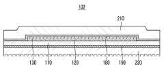
도 1은 본 발명의 제1 실시예에 따른 유기 발광 표시 장치의 단면도이다.1 is a cross-sectional view of an organic light emitting diode display according to a first exemplary embodiment of the present invention.
도 1에 도시된 바와 같이, 본 발명의 제1 실시예에 따른 유기 발광 표시 장치(101)는 가요성 기판(110), 구동 회로부(120), 유기 발광 소자(130), 봉지 박막(180), 열 전도층(190), 제1 필름(210) 및 제2 필름(220)을 포함한다.As shown in FIG. 1, the organic light
가요성 기판(110)은 플라스틱 또는 수지 등으로 이루어진 가소성 기판을 포함한다. 가요성 기판(110) 상에는 구동 회로부(120) 및 유기 발광 소자(130)가 위치하고 있다.The
구동 회로부(120)는 제1 및 제2 박막 트랜지스터(10, 20)(도 2에 도시)를 포함하며, 유기 발광 소자(130)를 구동한다. 유기 발광 소자(130)는 구동 회로부(120)로부터 전달받은 구동 신호에 따라 빛을 방출한다.The
이하, 도 2 및 도 3을 참조하여, 유기 발광 표시 장치(101)의 내부 구조에 대해 상세히 설명한다.Hereinafter, the internal structure of the organic light
이하에서 자세히 설명할 구동 회로부(120) 및 유기 발광 소자(130)의 구체적인 구조는 도 2 및 도 3에 나타나 있으나, 본 발명의 실시예가 도 2 및 도 3에 도시된 구조에 한정되는 것은 아니다. 구동 회로부(120) 및 유기 발광 소자(130)는 해당 기술 분야의 전문가가 용이하게 변형 실시할 수 있는 범위 내에서 다양한 구 조로 형성될 수 있다.Specific structures of the
도 2은 본 발명의 제1 실시예에 따른 유기 발광 표시 장치의 화소의 구조를 나타낸 배치도이다. 도 3는 도 2의 Ⅲ-Ⅲ 선을 따른 단면도이다.2 is a layout view illustrating a pixel structure of an organic light emitting diode display according to a first exemplary embodiment of the present invention. 3 is a cross-sectional view taken along line III-III of FIG. 2.
도 2 및 도 3에 도시한 바와 같이, 유기 발광 표시 장치(101)는 하나의 화소마다 각각 형성된 스위칭 박막 트랜지스터(10), 구동 박막 트랜지스터(20), 축전 소자(80), 그리고 유기 발광 소자(organic light emitting diode, OLED)(130)를 포함한다. 여기서, 스위칭 박막 트랜지스터(10), 구동 박막 트랜지스터(20) 및 축전 소자(80)를 포함하는 구성을 구동 회로부(120)라 한다. 그리고, 구동 회로부(120)는 가요성 기판(110)의 일 방향을 따라 배치되는 게이트 라인(151), 게이트 라인(151)과 절연 교차되는 데이터 라인(171) 및 공통 전원 라인(172)을 더 포함한다. 여기서, 하나의 화소는 게이트 라인(151), 데이터 라인(171) 및 공통 전원 라인(172)을 경계로 정의될 수 있으나, 반드시 이에 한정되는 것은 아니다.As shown in FIGS. 2 and 3, the organic light
유기 발광 소자(130)는 제1 전극(710)과, 제1 전극(710) 상에 형성된 유기 발광층(720)과, 유기 발광층(720) 상에 형성된 제2 전극(730)을 포함한다. 여기서, 제1 전극(710)은 정공 주입 전극인 양(+)극이며, 제2 전극(730)은 전자 주입 전극인 음(-)극이 된다. 그러나 본 발명의 제1 실시예가 반드시 이에 한정되는 것은 아니며, 표시 장치(101)의 구동 방법에 따라 제1 전극(710)이 음극이 되고, 제2 전극(730)이 양극이 될 수도 있다. 제1 전극(710) 및 제2 전극(730)으로부터 각각 정공과 전자가 유기 발광층(720) 내부로 주입되며, 유기 발광층(720) 내부로 주입된 정공과 전자가 결합한 엑시톤(exiton)이 여기 상태로부터 기저 상태로 떨어질 때 유기 발광층(720)의 발광이 이루어진다.The organic
또한, 본 발명의 제1 실시예에 따른 유기 발광 표시 장치(101)에서 유기 발광 소자(70)는 봉지 박막(180) 방향으로 빛을 방출한다. 즉, 유기 발광 소자(130)는 전면 발광형이다. 여기서, 유기 발광 소자(130)가 봉지 박막(180) 방향으로 빛을 방출하기 위해, 제1 전극(710)으로는 반사형 전극이 사용되고 제2 전극(730)으로는 투과형 또는 반투과형 전극이 사용된다. 그러나 본 발명의 제1 실시예에서, 유기 발광 표시 장치(101)가 전면 발광형에 한정되는 것은 아니다. 따라서, 유기 발광 표시 장치(101)는 후면 발광형 또는 양면 발광형일 수도 있다.In the organic light
축전 소자(80)는 층간 절연막(161)을 사이에 두고 배치된 한 쌍의 축전판(158, 178)을 포함한다. 여기서, 층간 절연막(161)은 유전체가 되며, 축전 소자(80)에서 축전된 전하와 양 축전판(158, 178) 사이의 전압에 의해 축전 소자(80)의 축전 용량이 결정된다.The
스위칭 박막 트랜지스터(10)는 스위칭 반도체층(131), 스위칭 게이트 전극(152), 스위칭 소스 전극(173) 및 스위칭 드레인 전극(174)을 포함한다. 구동 박막 트랜지스터(20)는 구동 반도체층(132), 구동 게이트 전극(155), 구동 소스 전극(176) 및 구동 드레인 전극(177)을 포함한다.The switching
스위칭 박막 트랜지스터(10)는 발광시키고자 하는 화소를 선택하는 스위칭 소자로서 사용된다. 스위칭 게이트 전극(152)은 게이트 라인(151)에 연결된다. 스위칭 소스 전극(173)은 데이터 라인(171)에 연결된다. 스위칭 드레인 전극(174)은 스위칭 소스 전극(173)으로부터 이격 배치되며 어느 한 축전판(158)과 연결된 다.The switching
구동 박막 트랜지스터(20)는 선택된 화소 내의 유기 발광 소자(130)의 유기 발광층(720)을 발광시키기 위한 구동 전원을 제1 전극(710)에 인가한다. 구동 게이트 전극(155)은 스위칭 드레인 전극(174)과 연결된 축전판(158)과 연결된다. 구동 소스 전극(176) 및 다른 한 축전판(178)은 각각 공통 전원 라인(172)과 연결된다. 구동 드레인 전극(177)은 컨택홀(contact hole)을 통해 유기 발광 소자(130)의 제1 전극(710)과 연결된다.The driving
이와 같은 구조에 의하여, 스위칭 박막 트랜지스터(10)는 게이트 라인(151)에 인가되는 게이트 전압에 의해 작동하여 데이터 라인(171)에 인가되는 데이터 전압을 구동 박막 트랜지스터(20)로 전달하는 역할을 한다. 공통 전원 라인(172)으로부터 구동 박막 트랜지스터(20)에 인가되는 공통 전압과 스위칭 박막 트랜지스터(10)로부터 전달된 데이터 전압의 차에 해당하는 전압이 축전 소자(80)에 저장되고, 축전 소자(80)에 저장된 전압에 대응하는 전류가 구동 박막 트랜지스터(20)를 통해 유기 발광 소자(130)로 흘러 유기 발광 소자(130)가 발광하게 된다.By such a structure, the switching
유기 발광 소자(130)를 사이에 두고 가요성 기판(110)과 대향하여 봉지 박막(180)이 위치하고 있다.The encapsulation
다시, 도 1을 참조하면, 봉지 박막(180)은 가요성 기판(110) 상에 위치하며, 봉지 박막(180)과 가요성 기판(110) 사이에는 구동 회로부(120) 및 유기 발광 소자(130)가 개재되어 있다. 봉지 박막(180)은 유기 발광 소자(130)를 봉지하며, 수지 또는 실리카 계열의 무기물로 이루어진다.Referring back to FIG. 1, the encapsulation
봉지 박막(180)과 대향하여 가요성 기판(110)을 사이에 두고 열 전도층(190)이 위치하고 있다.The heat
열 전도층(190)은 가요성 기판(110)을 사이에 두고 유기 발광 소자(130)와 대향하며, 가요성 기판(110)의 판면과 접하고 있다. 열 전도층(190)은 가요성 기판(110)의 판면 전체에 걸쳐서 대응한다. 열 전도층(190)은 금(Au), 은(Ag), 구리(Ti), 몰리브덴(Mo) 또는 알루미늄(Al) 등과 같은 열전도 계수가 높은 금속으로 이루어진다. 열 전도층(190)은 가요성 기판(110), 제1 필름(210) 및 제2 필름(220) 대비 열전도 계수가 크며, 가요성 기판(110)과 제2 필름(220) 사이에서 가요성 기판(110)의 판면과 접하고 있어 가요성 기판(110) 상에 위치하는 유기 발광 소자(130)에서 발생된 열을 제2 필름(220) 방향으로 전도하는 것을 도와주는 역할을 한다. 열 전도층(190)에 의한 본 발명의 제1 실시예에 따른 유기 발광 표시 장치(101)의 방열 효율에 대해서는 후술한다.The thermal
도 4는 본 발명의 제1 실시예에 따른 유기 발광 표시 장치에 포함된 열 전도층의 일 예를 도시한 사시도이다. 열 전도층(190)은 도 4의 (a)에 도시된 바와 같은 판 형태이거나, 또는 도 4의 (b)에 도시된 바와 같은 그물망 형태일 수 있다.4 is a perspective view illustrating an example of a thermal conductive layer included in an organic light emitting diode display according to a first exemplary embodiment of the present invention. The thermal
다시 도 1을 참조하면, 제1 필름(210)은 봉지 박막(180)에 부착되어 있으며, 가요성 기판(110), 구동 회로부(120) 및 유기 발광 소자(130)를 합친 두께 대비 두꺼운 두께를 가지고 있다. 제1 필름(210)은 제2 필름(220)과 함께 가요성 기판(110), 구동 회로부(120) 및 유기 발광 소자(130)를 덮고 있으며, 본 발명의 제1 실시예에 따른 유기 발광 표시 장치(101)의 기계적 강도를 향상시키는 역할을 한 다. 제1 필름(210)은 수지 등으로 이루어진다.Referring back to FIG. 1, the
제2 필름(220)은 열 전도층(190)에 부착되어 있으며, 가요성 기판(110), 구동 회로부(120) 및 유기 발광 소자(130)를 합친 두께 대비 두꺼운 두께를 가지고 있다. 제2 필름(220)은 제1 필름(210)과 함께 가요성 기판(110), 구동 회로부(120) 및 유기 발광 소자(130)를 덮고 있으며, 본 발명의 제1 실시예에 따른 유기 발광 표시 장치(101)의 기계적 강도를 향상시키는 역할을 한다. 제2 필름(220)은 수지 등으로 이루어진다.The
이하, 도 5를 참조하여 본 발명의 제1 실시예에 따른 유기 발광 표시 장치(101)의 방열 효율에 대하여 자세히 설명한다.Hereinafter, the heat dissipation efficiency of the organic light emitting
도 5는 도 1의 A 부분의 확대도이다.5 is an enlarged view of a portion A of FIG. 1.
도 5에 도시된 바와 같이, 본 발명의 제1 실시예에 따른 유기 발광 표시 장치(101)는 전도, 복사 및 대류 현상을 이용하여 유기 발광 소자(130)로부터 발생된 열(H)을 외부로 방열한다.As illustrated in FIG. 5, the organic light emitting
우선, 전도 현상에 대하여 설명한다.First, the conduction phenomenon will be described.
전도 현상은 고체에서 온도가 높은 쪽에서 낮은 쪽으로 열(H)이 전달되는 현상이다. 전도 현상은 다음의 수학식 1과 같이 표현된다.The conduction phenomenon is the transfer of heat (H) from the solid to the high and low temperatures. The conduction phenomenon is expressed by Equation 1 below.
[수학식 1][Equation 1]

여기서, q는 시간당 전도되는 열 에너지량, k는 열전도 계수, A는 고체의 접 촉 면적, dT는 고체에서 온도가 높은 표면의 온도로부터 온도가 낮은 표면의 온도를 마이너스한 온도, dx는 고체의 두께이다.Where q is the amount of thermal energy conducted per hour, k is the thermal conductivity coefficient, A is the contact area of the solid, dT is the temperature of the solid surface minus the temperature of the lower surface temperature, and dx is the Thickness.
상기 수학식 1에서 보는 바와 같이, 전도 현상에 따라 시간당 전도되는 열 에너지량은 열전도 계수(k) 및 접촉 면적(A)에 비례한다.As shown in Equation 1, the amount of thermal energy conducted per hour according to the conduction phenomenon is proportional to the thermal conductivity coefficient k and the contact area A.
본 발명의 제1 실시예에 따른 유기 발광 표시 장치(101)의 열 전도층(190)은 접해있는 가요성 기판(110) 및 제2 필름(220) 대비 열전도 계수(k)가 높고, 가요성 기판(110)의 판면 전체에 걸쳐서 판 형태로 대응하여 가요성 기판(110)과 접해 있기 때문에, 가요성 기판(110)과 높은 접촉 면적(A)을 이루고 있다. 즉, 전도 현상에 의해, 유기 발광 소자(130)로부터 발생되어 가요성 기판(110)을 거쳐 열 전도층(190)으로 시간당 전도되는 열 에너지량(q)이 증가된다.The thermal
또한, 열 전도층(190)으로 전도된 열(H)은 열 전도층(190) 내 전체에 걸쳐서 골고루 분산되며, 이 분산된 열(H)은 열 전도층(190)에 부착된 제2 필름(220)으로 골고루 전달된다.In addition, the heat (H) conducted to the
다음, 복사 현상에 대하여 설명한다.Next, the copy phenomenon will be described.
복사 현상은 물체의 온도에 따라서 물체로부터 외부로 복사열이 발생하는 현상이다. 복사 현상은 다음의 수학식 2와 같이 표현된다.Radiation phenomenon is a phenomenon that radiant heat is generated from the object to the outside depending on the temperature of the object. The radiation phenomenon is expressed by Equation 2 below.
[수학식 2][Equation 2]

여기서 P는 시간당 복사되는 열 에너지량, δ는 스테판 상수(Stefan’s Constant), B는 물체의 표면적, T는 물체의 온도이다.Where P is the amount of heat energy radiated per hour, δ is Stefan's Constant, B is the surface area of the object, and T is the temperature of the object.
상기 수학식 2에서 보는 바와 같이, 복사 현상은 물체의 표면적(B)에 비례한다.As shown in Equation 2, the radiation phenomenon is proportional to the surface area B of the object.
본 발명의 제1 실시예에 따른 유기 발광 표시 장치(101)는 유기 발광 소자(130)로부터 발생된 열(H)이 열 전도층(190)에 의해 제2 필름(220) 전체에 걸쳐서 골고루 전달되기 때문에, 제2 필름(220)의 국부적 표면이 아닌 전체 표면에서 복사 현상이 수행된다. 즉, 본 발명의 제1 실시예에 따른 유기 발광 표시 장치(101)는 높은 표면적(B)으로부터 복사 현상이 수행됨으로써, 제2 필름(220)으로부터 외부로 시간당 복사되는 열 에너지량(P)이 증가된다.In the organic light emitting
요컨대, 유기 발광 소자(130)로부터 국부적으로 발생된 열(H)은 가요성 기판(110)을 거쳐 열 전도층(190)으로 전도된 후, 가요성 기판(110) 전체에 대응하는 열 전도층(190) 전체에 걸쳐서 전도되어 다시 제2 필름(220) 전체에 걸쳐서 전도됨으로써, 제2 필름(220)의 전체 표면에서 복사 현상이 수행되어 제2 필름(220)으로부터 외부로 시간당 복사되는 열 에너지량(P)이 증가된다.In other words, the heat H generated locally from the organic
다음, 대류 현상에 대하여 설명한다.Next, the convection phenomenon will be described.
대류 현상은 액체나 기체에서 발생하는 현상으로서 뜨거운 부분은 위로 올라가고 차가운 부분은 아래로 내려가는 현상이다. 즉, 가열된 공기나 유체가 움직이면서 열(H)이 전달되는 현상을 대류 현상이라 한다.Convection occurs in liquids or gases, where hot parts go up and cold parts go down. That is, the phenomenon that heat (H) is transmitted while the heated air or fluid moves is called a convection phenomenon.
본 발명의 제1 실시예에 따른 유기 발광 표시 장치(101)에서 복사 현상에 의해 유기 발광 표시 장치(101)로부터 외부와 인접한 공간으로 복사된 열(H)은 대류 현상에 의해 외부로부터 떨어진 공간으로 이동함으로써, 유기 발광 소자(130)에 대한 유기 발광 표시 장치(101)의 방열이 수행된다.In the organic light emitting
이상과 같이, 본 발명의 제1 실시예에 따른 유기 발광 표시 장치(101)는 가요성 기판(110)과 제2 필름(220) 사이에 위치하는 열 전도층(190)을 포함함으로써, 유기 발광 표시 장치(101) 자체 내의 전도 현상 및 복사 현상에 따라 이동하는 열 에너지량이 증가된다. 즉, 본 발명의 제1 실시예에 따른 유기 발광 표시 장치(101)는 열 전도층(190)을 포함함으로써, 유기 발광 소자(130)에 대한 방열 효율이 향상된다.As described above, the organic light emitting
이하, 도 6를 참조하여 본 발명의 제2 실시예에 따른 유기 발광 표시 장치(101)에 대하여 설명한다.Hereinafter, the organic light emitting
도 6은 본 발명의 제2 실시예에 따른 유기 발광 표시 장치를 나타낸 단면도이다.6 is a cross-sectional view of an organic light emitting diode display according to a second exemplary embodiment of the present invention.
도 6에 도시된 바와 같이, 본 발명의 제2 실시예에 따른 유기 발광 표시 장치(101)에서, 외부의 공기와 접하는 제2 필름(220)의 표면은 요철(凹凸) 형태이다.As illustrated in FIG. 6, in the organic light emitting
상술한 수학식 2에서 보는 바와 같이, 복사 현상은 물체의 표면적(B)에 비례한다.As shown in Equation 2, the radiation phenomenon is proportional to the surface area B of the object.
본 발명의 제2 실시예에 따른 유기 발광 표시 장치(101)는 유기 발광 소자(130)로부터 발생된 열이 열 전도층(190)에 의해 제2 필름(220) 전체에 걸쳐서 골고루 전달되기 때문에, 제2 필름(220)의 국부적 표면이 아닌 전체 표면에서 복사 현상이 수행되는데, 제2 필름(220)의 표면이 요철 형태로 구성됨으로써, 제2 필름(220)의 표면 자체가 높은 표면적(B)을 가지게 되어 제2 필름(220)으로부터 외부로 시간당 복사되는 열 에너지량(P)이 증가된다.In the organic light emitting
이상과 같이, 본 발명의 제2 실시예에 따른 유기 발광 표시 장치(101)는 제2 필름(220)의 표면이 요철 형태로 구성되어 제2 필름(220)의 표면적(B)이 증가됨으로써, 제2 필름(220)으로부터 외부로 시간당 복사되는 열 에너지량이 증가된다. 즉, 본 발명의 제2 실시예에 따른 유기 발광 표시 장치(101)는 유기 발광 소자(130)에 대한 방열 효율이 향상된다.As described above, in the organic light emitting
이하, 도 7 내지 도 11을 참조하여 본 발명의 제1 실시예에 따른 유기 발광 표시 장치(101)의 제조 방법을 설명한다.Hereinafter, a method of manufacturing the organic light emitting
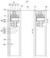
도 7은 본 발명의 제1 실시예에 따른 유기 발광 표시 장치의 제조 방법을 나타낸 순서도이다. 도 8 내지 도 11은 본 발명의 제1 실시예에 따른 유기 발광 표시 장치의 제조 방법을 설명하기 위한 도면이다.7 is a flowchart illustrating a method of manufacturing an organic light emitting display device according to a first embodiment of the present invention. 8 to 11 illustrate a method of manufacturing an organic light emitting diode display according to a first exemplary embodiment of the present invention.
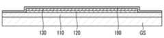
우선, 도 7 및 도 8에 도시된 바와 같이, 유리 기판(GS) 상에 가요성 기판(110)을 형성한다(S110).First, as shown in FIGS. 7 and 8, the
구체적으로, 스핀 코팅(spin coating) 등의 코팅 공정을 이용하여 유리 기판(GS) 상에 플라스틱 또는 수지 재질을 코팅하여 가요성 기판(110)을 형성한다.Specifically, the
다음, 가요성 기판(110) 상에 구동 회로부(120) 및 유기 발광 소자(130)를 형성한다(S120).Next, the driving
구체적으로, 포토리소그래피(photolithography) 공정 등의 멤 스(microelectromechanical systems) 기술을 이용하여 가요성 기판(110) 상에 구동 회로부(120) 및 유기 발광 소자(130)를 형성한다.Specifically, the driving
다음, 유기 발광 소자(130) 상에 봉지 박막(180)을 형성하여 유기 발광 소자(130)를 봉지한다(S130).Next, an encapsulation
구체적으로, 유기 발광 소자(130) 상에 증착 공정, 부착 공정 또는 코팅 공정 등을 이용하여 유기 발광 소자(130)를 봉지하도록 봉지 박막(180)을 형성한다.Specifically, the encapsulation
다음, 도 9에 도시된 바와 같이, 가요성 기판(110)으로부터 유리 기판(GS)을 분리한다(S140).Next, as shown in FIG. 9, the glass substrate GS is separated from the flexible substrate 110 (S140).
구체적으로, 가요성 기판(110)으로부터 유리 기판(GS)을 분리하는데, 유리 기판(GS)과 가요성 기판(110) 사이를 분리시켜 가요성 기판(110)으로부터 유리 기판(GS)을 분리하거나, 또는 유리 기판(GS)만을 선택적으로 식각할 수 있는 식각액을 이용하여 가요성 기판(110)으로부터 유리 기판(GS)을 분리한다.Specifically, the glass substrate GS is separated from the
다음, 도 10에 도시된 바와 같이, 가요성 기판(110)의 판면에 가요성 기판(110)과 접하는 열 전도층(190)을 형성한다(S150).Next, as shown in FIG. 10, a thermal
구체적으로, 유리 기판(GS)이 분리된 가요성 기판(110)의 판면에 가요성 기판(110)의 판면 전체에 걸쳐서 대응하는 동시에 가요성 기판(110)과 접하는 열 전도층(190)을 형성한다. 열 전도층(190)은 화학 기상 증착(chemical vapor deposition, CVD) 공정 등의 증착 공정을 이용하여 가요성 기판(110)의 판면에 증착되거나, 또는 부착 공정을 이용하여 가요성 기판(110)의 판면에 부착된다.Specifically, the
다음, 도 11에 도시된 바와 같이, 봉지 박막(180)에 제1 필름(210)을 부착한 다(S160).Next, as shown in FIG. 11, the
구체적으로, 부착 공정을 이용하여 봉지 박막(180)과 접하는 제1 필름(210)을 봉지 박막(180)에 부착한다.Specifically, the
다음, 열 전도층(190)에 제2 필름(220)을 부착한다.Next, the
구체적으로, 부착 공정을 이용하여 열 전도층(190)과 접하는 제2 필름(220)을 열 전도층(190)에 부착한다.Specifically, the
이상과 같은 공정에 의해, 본 발명의 제1 실시예에 따른 유기 발광 표시 장치(101)가 제조된다.Through the above steps, the organic light emitting
본 발명을 앞서 기재한 바에 따라 바람직한 실시예를 통해 설명하였지만, 본 발명은 이에 한정되지 않으며 다음에 기재하는 특허청구범위의 개념과 범위를 벗어나지 않는 한, 다양한 수정 및 변형이 가능하다는 것을 본 발명이 속하는 기술 분야에 종사하는 자들은 쉽게 이해할 것이다.While the invention has been shown and described with reference to certain preferred embodiments thereof, it will be understood by those skilled in the art that various changes and modifications may be made therein without departing from the spirit and scope of the following claims. Those who are engaged in the technology field will understand easily.
도 1은 본 발명의 제1 실시예에 따른 유기 발광 표시 장치의 단면도이다.1 is a cross-sectional view of an organic light emitting diode display according to a first exemplary embodiment of the present invention.
도 2는 본 발명의 제1 실시예에 따른 유기 발광 표시 장치의 화소의 구조를 나타낸 배치도이다.2 is a layout view illustrating a pixel structure of an organic light emitting diode display according to a first exemplary embodiment of the present invention.
도 3은 도 2의 Ⅲ-Ⅲ 선을 따른 단면도이다.3 is a cross-sectional view taken along line III-III of FIG. 2.
도 4는 본 발명의 제1 실시예에 따른 유기 발광 표시 장치에 포함된 열 전도층의 일 예를 도시한 사시도이다.4 is a perspective view illustrating an example of a thermal conductive layer included in an organic light emitting diode display according to a first exemplary embodiment of the present invention.
도 5는 도 1의 A 부분의 확대도이다.5 is an enlarged view of a portion A of FIG. 1.
도 6은 본 발명의 제2 실시예에 따른 유기 발광 표시 장치를 나타낸 단면도이다.6 is a cross-sectional view of an organic light emitting diode display according to a second exemplary embodiment of the present invention.
도 7은 본 발명의 제1 실시예에 따른 유기 발광 표시 장치의 제조 방법을 나타낸 순서도이다.7 is a flowchart illustrating a method of manufacturing an organic light emitting display device according to a first embodiment of the present invention.
도 8 내지 도 11은 본 발명의 제1 실시예에 따른 유기 발광 표시 장치의 제조 방법을 설명하기 위한 도면이다.8 to 11 illustrate a method of manufacturing an organic light emitting diode display according to a first exemplary embodiment of the present invention.
Claims (14)
Translated fromKoreanPriority Applications (2)
| Application Number | Priority Date | Filing Date | Title |
|---|---|---|---|
| KR1020090110476AKR101084230B1 (en) | 2009-11-16 | 2009-11-16 | Organic light emitting display device and manufacturing method of organic light emitting display device |
| US12/946,710US8994063B2 (en) | 2009-11-16 | 2010-11-15 | Organic light emitting diode display and method of manufacturing the same |
Applications Claiming Priority (1)
| Application Number | Priority Date | Filing Date | Title |
|---|---|---|---|
| KR1020090110476AKR101084230B1 (en) | 2009-11-16 | 2009-11-16 | Organic light emitting display device and manufacturing method of organic light emitting display device |
Publications (2)
| Publication Number | Publication Date |
|---|---|
| KR20110053801A KR20110053801A (en) | 2011-05-24 |
| KR101084230B1true KR101084230B1 (en) | 2011-11-16 |
Family
ID=44010646
Family Applications (1)
| Application Number | Title | Priority Date | Filing Date |
|---|---|---|---|
| KR1020090110476AActiveKR101084230B1 (en) | 2009-11-16 | 2009-11-16 | Organic light emitting display device and manufacturing method of organic light emitting display device |
Country Status (2)
| Country | Link |
|---|---|
| US (1) | US8994063B2 (en) |
| KR (1) | KR101084230B1 (en) |
Families Citing this family (10)
| Publication number | Priority date | Publication date | Assignee | Title |
|---|---|---|---|---|
| KR20120042151A (en)* | 2010-10-22 | 2012-05-03 | 삼성모바일디스플레이주식회사 | Method of manufacturing flexible display apparatus |
| KR101830894B1 (en)* | 2011-09-09 | 2018-02-22 | 삼성디스플레이 주식회사 | Organic light emitting diode display device |
| KR101991863B1 (en)* | 2012-08-28 | 2019-06-24 | 삼성디스플레이 주식회사 | Encapsulation sheet, manufacturing method of organic light emitting display device comprising the same and organic light emitting display device |
| US20140061610A1 (en)* | 2012-08-31 | 2014-03-06 | Hyo-Young MUN | Organic light emitting device and manufacturing method thereof |
| KR102062842B1 (en) | 2013-06-03 | 2020-01-07 | 삼성디스플레이 주식회사 | Organic light emitting diode display and manufacturing method thereof |
| CN105990530A (en)* | 2015-01-27 | 2016-10-05 | 上海和辉光电有限公司 | Method for manufacturing OLED module having heat dissipation function, and heat dissipation structure |
| KR102437100B1 (en)* | 2015-10-13 | 2022-08-29 | 삼성디스플레이 주식회사 | Display apparatus for vehicle and vehicle including the same |
| WO2018037113A1 (en)* | 2016-08-26 | 2018-03-01 | Osram Oled Gmbh | Method for producing a component module, and component module |
| KR102687092B1 (en)* | 2016-10-27 | 2024-07-22 | 엘지디스플레이 주식회사 | Display device and method for manufacturing of the same |
| CN108242424B (en)* | 2016-12-26 | 2019-09-03 | 京东方科技集团股份有限公司 | Manufacturing method of flexible panel, flexible panel and display device |
Citations (2)
| Publication number | Priority date | Publication date | Assignee | Title |
|---|---|---|---|---|
| JP2002063985A (en)* | 2000-08-22 | 2002-02-28 | Nec Corp | Organic electroluminescence device |
| KR100796129B1 (en) | 2007-01-30 | 2008-01-21 | 삼성에스디아이 주식회사 | Organic electroluminescent display and manufacturing method |
Family Cites Families (57)
| Publication number | Priority date | Publication date | Assignee | Title |
|---|---|---|---|---|
| US5147821A (en)* | 1990-09-28 | 1992-09-15 | Motorola, Inc. | Method for making a thermally enhanced semiconductor device by holding a leadframe against a heatsink through vacuum suction in a molding operation |
| US5427858A (en)* | 1990-11-30 | 1995-06-27 | Idemitsu Kosan Company Limited | Organic electroluminescence device with a fluorine polymer layer |
| US6326678B1 (en)* | 1993-09-03 | 2001-12-04 | Asat, Limited | Molded plastic package with heat sink and enhanced electrical performance |
| EP0781075B1 (en)* | 1994-09-08 | 2001-12-05 | Idemitsu Kosan Company Limited | Method for sealing organic el element and organic el element |
| US5701951A (en)* | 1994-12-20 | 1997-12-30 | Jean; Amigo | Heat dissipation device for an integrated circuit |
| US5811177A (en)* | 1995-11-30 | 1998-09-22 | Motorola, Inc. | Passivation of electroluminescent organic devices |
| CN1134039C (en)* | 1996-08-12 | 2004-01-07 | 普林斯顿大学理事会 | Non-polymeric flexible organic light emitting device |
| KR100249784B1 (en)* | 1997-11-20 | 2000-04-01 | 정선종 | Packaging method of organic or polymer electroluminescent device using polymer composite membrane |
| HK1043664A1 (en)* | 1999-04-28 | 2002-09-20 | E‧I‧内穆尔杜邦公司 | Flexible organic electronic device with improved resistance to oxygen and moisture degradation |
| TWI232595B (en)* | 1999-06-04 | 2005-05-11 | Semiconductor Energy Lab | Electroluminescence display device and electronic device |
| US6573652B1 (en)* | 1999-10-25 | 2003-06-03 | Battelle Memorial Institute | Encapsulated display devices |
| US6110306A (en)* | 1999-11-18 | 2000-08-29 | The United States Of America As Represented By The Secretary Of The Navy | Complexed liquid fuel compositions |
| WO2001039258A1 (en)* | 1999-11-22 | 2001-05-31 | Sony Corporation | Functional device and method of manufacturing the same |
| US6677709B1 (en)* | 2000-07-18 | 2004-01-13 | General Electric Company | Micro electromechanical system controlled organic led and pixel arrays and method of using and of manufacturing same |
| TW548860B (en)* | 2001-06-20 | 2003-08-21 | Semiconductor Energy Lab | Light emitting device and method of manufacturing the same |
| US7211828B2 (en)* | 2001-06-20 | 2007-05-01 | Semiconductor Energy Laboratory Co., Ltd. | Light emitting device and electronic apparatus |
| TW546857B (en)* | 2001-07-03 | 2003-08-11 | Semiconductor Energy Lab | Light-emitting device, method of manufacturing a light-emitting device, and electronic equipment |
| US6841857B2 (en)* | 2001-07-18 | 2005-01-11 | Infineon Technologies Ag | Electronic component having a semiconductor chip, system carrier, and methods for producing the electronic component and the semiconductor chip |
| JP3818102B2 (en)* | 2001-08-31 | 2006-09-06 | 住友電気工業株式会社 | Heat dissipation substrate, method for manufacturing the same, and semiconductor device |
| JP4166455B2 (en)* | 2001-10-01 | 2008-10-15 | 株式会社半導体エネルギー研究所 | Polarizing film and light emitting device |
| US6698500B2 (en)* | 2002-01-22 | 2004-03-02 | The Furukawa Electric Co., Ltd. | Heat sink with fins |
| US6642092B1 (en)* | 2002-07-11 | 2003-11-04 | Sharp Laboratories Of America, Inc. | Thin-film transistors formed on a metal foil substrate |
| TW560703U (en)* | 2002-10-25 | 2003-11-01 | Ritdisplay Corp | Organic light-emitting diode |
| US6888172B2 (en)* | 2003-04-11 | 2005-05-03 | Eastman Kodak Company | Apparatus and method for encapsulating an OLED formed on a flexible substrate |
| US7648925B2 (en)* | 2003-04-11 | 2010-01-19 | Vitex Systems, Inc. | Multilayer barrier stacks and methods of making multilayer barrier stacks |
| AT500259B1 (en)* | 2003-09-09 | 2007-08-15 | Austria Tech & System Tech | THIN-LAYER ASSEMBLY AND METHOD FOR PRODUCING SUCH A THIN-LAYER ASSEMBLY |
| KR101176539B1 (en)* | 2003-11-04 | 2012-08-24 | 삼성전자주식회사 | Method of forming poly-silicon film, Thin Film Transistor comprising poly-silicon film formed using the same and method of manufacturing the same |
| US7612498B2 (en) | 2003-11-27 | 2009-11-03 | Toshiba Matsushita Display Technology Co., Ltd. | Display element, optical device, and optical device manufacturing method |
| CN1895003A (en)* | 2003-12-30 | 2007-01-10 | 新加坡科技研究局 | flexible electroluminescent element |
| KR20050073855A (en) | 2004-01-12 | 2005-07-18 | 삼성전자주식회사 | Flexible display and manufacturing method thereof |
| US7087134B2 (en)* | 2004-03-31 | 2006-08-08 | Hewlett-Packard Development Company, L.P. | System and method for direct-bonding of substrates |
| KR100601950B1 (en)* | 2004-04-08 | 2006-07-14 | 삼성전자주식회사 | Electronic device and manufacturing method thereof |
| US7205718B2 (en)* | 2004-06-24 | 2007-04-17 | Eastman Kodak Company | OLED display having thermally conductive adhesive |
| TWI249232B (en)* | 2004-10-20 | 2006-02-11 | Siliconware Precision Industries Co Ltd | Heat dissipating package structure and method for fabricating the same |
| US20090008792A1 (en)* | 2004-11-19 | 2009-01-08 | Industrial Technology Research Institute | Three-dimensional chip-stack package and active component on a substrate |
| JP4556174B2 (en)* | 2004-12-15 | 2010-10-06 | 日本電気株式会社 | Portable terminal device and heat dissipation method |
| US7368307B2 (en)* | 2005-06-07 | 2008-05-06 | Eastman Kodak Company | Method of manufacturing an OLED device with a curved light emitting surface |
| KR100696851B1 (en) | 2005-07-29 | 2007-03-19 | 엘지전자 주식회사 | Structure for light emitting element array |
| KR100795786B1 (en)* | 2005-12-06 | 2008-01-17 | 삼성에스디아이 주식회사 | Plasma display module |
| KR100635514B1 (en)* | 2006-01-23 | 2006-10-18 | 삼성에스디아이 주식회사 | Organic light emitting display device and manufacturing method |
| US20080080142A1 (en)* | 2006-09-28 | 2008-04-03 | Mediatek Inc. | Electronic devices with enhanced heat spreading |
| US7977170B2 (en)* | 2006-10-03 | 2011-07-12 | Eastman Kodak Company | Flexible substrate with electronic devices and traces |
| AU2006350626B2 (en)* | 2006-11-06 | 2013-09-19 | Agency For Science, Technology And Research | Nanoparticulate encapsulation barrier stack |
| US7968382B2 (en)* | 2007-02-02 | 2011-06-28 | Semiconductor Energy Laboratory Co., Ltd. | Method of manufacturing semiconductor device |
| US7973473B2 (en)* | 2007-03-02 | 2011-07-05 | Global Oled Technology Llc | Flat panel OLED device having deformable substrate |
| KR100841376B1 (en)* | 2007-06-12 | 2008-06-26 | 삼성에스디아이 주식회사 | Bonding method and manufacturing method of organic light emitting display device using the same |
| TW200902954A (en)* | 2007-07-13 | 2009-01-16 | Univ Nat Taiwan | Miniaturized surface plasmon resonance sensing chip |
| KR100889625B1 (en)* | 2007-07-19 | 2009-03-20 | 삼성모바일디스플레이주식회사 | Bonding method and manufacturing method of organic light emitting display device using the same |
| EP2036734B1 (en)* | 2007-09-14 | 2010-12-29 | Punch Graphix International N.V. | Light emitting array for printing or copying |
| KR100943185B1 (en) | 2008-04-24 | 2010-02-19 | 삼성모바일디스플레이주식회사 | Organic light emitting display device |
| KR20080104324A (en) | 2008-09-19 | 2008-12-02 | 에이전시 포 사이언스, 테크놀로지 앤드 리서치 | Flexible electroluminescent device |
| KR101363022B1 (en)* | 2008-12-23 | 2014-02-14 | 삼성디스플레이 주식회사 | Organic light emitting diode display |
| JP5146356B2 (en)* | 2009-02-24 | 2013-02-20 | 豊田合成株式会社 | Light emitting device and manufacturing method thereof |
| KR101155907B1 (en)* | 2009-06-04 | 2012-06-20 | 삼성모바일디스플레이주식회사 | Organic light emitting diode display and method for manufacturing the same |
| JP2011071481A (en)* | 2009-08-28 | 2011-04-07 | Fujifilm Corp | Solid-state imaging device, process of making solid-state imaging device, digital still camera, digital video camera, mobile phone, and endoscope |
| JP5497417B2 (en)* | 2009-12-10 | 2014-05-21 | 富士フイルム株式会社 | THIN FILM TRANSISTOR, MANUFACTURING METHOD THEREOF, AND APPARATUS HAVING THE THIN FILM TRANSISTOR |
| KR20120118335A (en)* | 2011-04-18 | 2012-10-26 | 삼성디스플레이 주식회사 | Organic light emitting diode lighting apparatus |
- 2009
- 2009-11-16KRKR1020090110476Apatent/KR101084230B1/enactiveActive
- 2010
- 2010-11-15USUS12/946,710patent/US8994063B2/enactiveActive
Patent Citations (2)
| Publication number | Priority date | Publication date | Assignee | Title |
|---|---|---|---|---|
| JP2002063985A (en)* | 2000-08-22 | 2002-02-28 | Nec Corp | Organic electroluminescence device |
| KR100796129B1 (en) | 2007-01-30 | 2008-01-21 | 삼성에스디아이 주식회사 | Organic electroluminescent display and manufacturing method |
Also Published As
| Publication number | Publication date |
|---|---|
| US8994063B2 (en) | 2015-03-31 |
| US20110114993A1 (en) | 2011-05-19 |
| KR20110053801A (en) | 2011-05-24 |
Similar Documents
| Publication | Publication Date | Title |
|---|---|---|
| KR101084230B1 (en) | Organic light emitting display device and manufacturing method of organic light emitting display device | |
| KR102082407B1 (en) | Flexible substrate, flexible display device, and method for manufacturing flexible display device | |
| TW589915B (en) | Electroluminescence display device | |
| JP6105911B2 (en) | OLED display panel | |
| TWI360366B (en) | Oled display having thermally conductive backplate | |
| WO2019105088A1 (en) | Organic light emitting diode display substrate, manufacturing method therefor and display device | |
| CN101106156A (en) | Organic light emitting diode display and manufacturing method thereof | |
| CN100435380C (en) | Organic electroluminescence device with support plate and manufacturing method thereof | |
| CN107068724B (en) | OLED display panel and preparation method thereof, OLED display | |
| US7583022B2 (en) | OLED display with electrode | |
| KR100959106B1 (en) | Organic light emitting display | |
| KR20120106181A (en) | Organic light emitting diode display | |
| KR20150075184A (en) | Display Device and Method for Manufacturing The Same | |
| JP2007026970A (en) | Organic light emitting display | |
| KR20110038514A (en) | Organic light emitting display and manufacturing method thereof | |
| WO2018173415A1 (en) | Display device | |
| KR20120088025A (en) | Fabricating method of organic light emitting diode display panel | |
| KR101197758B1 (en) | Organic Light Emitting Diodes | |
| CN106098738B (en) | Organic light-emitting display device and preparation method thereof | |
| KR101564629B1 (en) | Organic electro-luminescence device | |
| TWI227095B (en) | Organic light emitting diode (OLED) display and fabrication method thereof | |
| KR20080108808A (en) | Organic light emitting diode | |
| KR100680805B1 (en) | Organic light emitting diode | |
| CN100395793C (en) | Organic electroluminescent display device | |
| JP2011187217A (en) | Organic el module |
Legal Events
| Date | Code | Title | Description |
|---|---|---|---|
| A201 | Request for examination | ||
| PA0109 | Patent application | St.27 status event code:A-0-1-A10-A12-nap-PA0109 | |
| PA0201 | Request for examination | St.27 status event code:A-1-2-D10-D11-exm-PA0201 | |
| E902 | Notification of reason for refusal | ||
| PE0902 | Notice of grounds for rejection | St.27 status event code:A-1-2-D10-D21-exm-PE0902 | |
| PG1501 | Laying open of application | St.27 status event code:A-1-1-Q10-Q12-nap-PG1501 | |
| E701 | Decision to grant or registration of patent right | ||
| PE0701 | Decision of registration | St.27 status event code:A-1-2-D10-D22-exm-PE0701 | |
| GRNT | Written decision to grant | ||
| PR0701 | Registration of establishment | St.27 status event code:A-2-4-F10-F11-exm-PR0701 | |
| PR1002 | Payment of registration fee | St.27 status event code:A-2-2-U10-U11-oth-PR1002 Fee payment year number:1 | |
| PG1601 | Publication of registration | St.27 status event code:A-4-4-Q10-Q13-nap-PG1601 | |
| PN2301 | Change of applicant | St.27 status event code:A-5-5-R10-R11-asn-PN2301 | |
| PN2301 | Change of applicant | St.27 status event code:A-5-5-R10-R14-asn-PN2301 | |
| FPAY | Annual fee payment | Payment date:20141030 Year of fee payment:4 | |
| PR1001 | Payment of annual fee | St.27 status event code:A-4-4-U10-U11-oth-PR1001 Fee payment year number:4 | |
| R18-X000 | Changes to party contact information recorded | St.27 status event code:A-5-5-R10-R18-oth-X000 | |
| FPAY | Annual fee payment | Payment date:20151030 Year of fee payment:5 | |
| PR1001 | Payment of annual fee | St.27 status event code:A-4-4-U10-U11-oth-PR1001 Fee payment year number:5 | |
| L13-X000 | Limitation or reissue of ip right requested | St.27 status event code:A-2-3-L10-L13-lim-X000 | |
| U15-X000 | Partial renewal or maintenance fee paid modifying the ip right scope | St.27 status event code:A-4-4-U10-U15-oth-X000 | |
| PR1001 | Payment of annual fee | St.27 status event code:A-4-4-U10-U11-oth-PR1001 Fee payment year number:6 | |
| FPAY | Annual fee payment | Payment date:20171101 Year of fee payment:7 | |
| PR1001 | Payment of annual fee | St.27 status event code:A-4-4-U10-U11-oth-PR1001 Fee payment year number:7 | |
| FPAY | Annual fee payment | Payment date:20181101 Year of fee payment:8 | |
| PR1001 | Payment of annual fee | St.27 status event code:A-4-4-U10-U11-oth-PR1001 Fee payment year number:8 | |
| FPAY | Annual fee payment | Payment date:20191028 Year of fee payment:9 | |
| PR1001 | Payment of annual fee | St.27 status event code:A-4-4-U10-U11-oth-PR1001 Fee payment year number:9 | |
| PR1001 | Payment of annual fee | St.27 status event code:A-4-4-U10-U11-oth-PR1001 Fee payment year number:10 | |
| PR1001 | Payment of annual fee | St.27 status event code:A-4-4-U10-U11-oth-PR1001 Fee payment year number:11 | |
| PR1001 | Payment of annual fee | St.27 status event code:A-4-4-U10-U11-oth-PR1001 Fee payment year number:12 | |
| P22-X000 | Classification modified | St.27 status event code:A-4-4-P10-P22-nap-X000 | |
| P22-X000 | Classification modified | St.27 status event code:A-4-4-P10-P22-nap-X000 | |
| PR1001 | Payment of annual fee | St.27 status event code:A-4-4-U10-U11-oth-PR1001 Fee payment year number:13 | |
| PR1001 | Payment of annual fee | St.27 status event code:A-4-4-U10-U11-oth-PR1001 Fee payment year number:14 | |
| P22-X000 | Classification modified | St.27 status event code:A-4-4-P10-P22-nap-X000 |