KR101084193B1 - OLED display and manufacturing method thereof - Google Patents
OLED display and manufacturing method thereofDownload PDFInfo
- Publication number
- KR101084193B1 KR101084193B1KR1020100013846AKR20100013846AKR101084193B1KR 101084193 B1KR101084193 B1KR 101084193B1KR 1020100013846 AKR1020100013846 AKR 1020100013846AKR 20100013846 AKR20100013846 AKR 20100013846AKR 101084193 B1KR101084193 B1KR 101084193B1
- Authority
- KR
- South Korea
- Prior art keywords
- pixel
- layer
- light emitting
- light
- pixel electrode
- Prior art date
- Legal status (The legal status is an assumption and is not a legal conclusion. Google has not performed a legal analysis and makes no representation as to the accuracy of the status listed.)
- Active
Links
- 238000004519manufacturing processMethods0.000titleclaimsabstractdescription16
- 125000006850spacer groupChemical group0.000claimsabstractdescription30
- 239000011810insulating materialSubstances0.000claimsabstractdescription16
- 230000000903blocking effectEffects0.000claimsabstractdescription12
- 238000005530etchingMethods0.000claimsabstractdescription5
- 238000000034methodMethods0.000claimsdescription16
- 238000002834transmittanceMethods0.000claimsdescription8
- 239000010410layerSubstances0.000description88
- 239000010408filmSubstances0.000description13
- 239000010409thin filmSubstances0.000description8
- 229920000642polymerPolymers0.000description6
- 238000002161passivationMethods0.000description5
- 238000007639printingMethods0.000description5
- 239000000758substrateSubstances0.000description5
- -1Ta 2 O 5Inorganic materials0.000description3
- 229910052782aluminiumInorganic materials0.000description3
- 229910052709silverInorganic materials0.000description3
- 229910052779NeodymiumInorganic materials0.000description2
- URLKBWYHVLBVBO-UHFFFAOYSA-NPara-XyleneChemical groupCC1=CC=C(C)C=C1URLKBWYHVLBVBO-UHFFFAOYSA-N0.000description2
- 229910052804chromiumInorganic materials0.000description2
- 230000002950deficientEffects0.000description2
- 229910052737goldInorganic materials0.000description2
- 238000002347injectionMethods0.000description2
- 239000007924injectionSubstances0.000description2
- 238000007641inkjet printingMethods0.000description2
- 229910052741iridiumInorganic materials0.000description2
- 239000007788liquidSubstances0.000description2
- 229910052744lithiumInorganic materials0.000description2
- 229910052749magnesiumInorganic materials0.000description2
- 229910044991metal oxideInorganic materials0.000description2
- 150000004706metal oxidesChemical class0.000description2
- 229910052759nickelInorganic materials0.000description2
- 229910052763palladiumInorganic materials0.000description2
- 229910052697platinumInorganic materials0.000description2
- 229910018072Al 2 O 3Inorganic materials0.000description1
- YCKRFDGAMUMZLT-UHFFFAOYSA-NFluorine atomChemical compound[F]YCKRFDGAMUMZLT-UHFFFAOYSA-N0.000description1
- 239000004642PolyimideSubstances0.000description1
- 229910004205SiNXInorganic materials0.000description1
- 229910004298SiO 2Inorganic materials0.000description1
- 229910010413TiO 2Inorganic materials0.000description1
- 239000000956alloySubstances0.000description1
- 229910045601alloyInorganic materials0.000description1
- 150000001408amidesChemical class0.000description1
- 150000008378aryl ethersChemical class0.000description1
- 230000005540biological transmissionEffects0.000description1
- 229910052791calciumInorganic materials0.000description1
- 239000002131composite materialSubstances0.000description1
- 239000000470constituentSubstances0.000description1
- 239000013078crystalSubstances0.000description1
- 229910052731fluorineInorganic materials0.000description1
- 239000011737fluorineSubstances0.000description1
- 239000011521glassSubstances0.000description1
- 150000003949imidesChemical class0.000description1
- 239000012535impuritySubstances0.000description1
- 238000009413insulationMethods0.000description1
- 239000000463materialSubstances0.000description1
- 239000002184metalSubstances0.000description1
- 229910052751metalInorganic materials0.000description1
- 239000000203mixtureSubstances0.000description1
- 238000012986modificationMethods0.000description1
- 230000004048modificationEffects0.000description1
- 230000035515penetrationEffects0.000description1
- ISWSIDIOOBJBQZ-UHFFFAOYSA-Nphenol groupChemical groupC1(=CC=CC=C1)OISWSIDIOOBJBQZ-UHFFFAOYSA-N0.000description1
- 229920000058polyacrylatePolymers0.000description1
- 229920001721polyimidePolymers0.000description1
- 229920002451polyvinyl alcoholPolymers0.000description1
- 239000011241protective layerSubstances0.000description1
- 229910052814silicon oxideInorganic materials0.000description1
Images


Classifications
- H—ELECTRICITY
- H10—SEMICONDUCTOR DEVICES; ELECTRIC SOLID-STATE DEVICES NOT OTHERWISE PROVIDED FOR
- H10K—ORGANIC ELECTRIC SOLID-STATE DEVICES
- H10K59/00—Integrated devices, or assemblies of multiple devices, comprising at least one organic light-emitting element covered by group H10K50/00
- H10K59/10—OLED displays
- H10K59/12—Active-matrix OLED [AMOLED] displays
- H10K59/122—Pixel-defining structures or layers, e.g. banks
- H—ELECTRICITY
- H05—ELECTRIC TECHNIQUES NOT OTHERWISE PROVIDED FOR
- H05B—ELECTRIC HEATING; ELECTRIC LIGHT SOURCES NOT OTHERWISE PROVIDED FOR; CIRCUIT ARRANGEMENTS FOR ELECTRIC LIGHT SOURCES, IN GENERAL
- H05B33/00—Electroluminescent light sources
- H05B33/12—Light sources with substantially two-dimensional radiating surfaces
- H05B33/22—Light sources with substantially two-dimensional radiating surfaces characterised by the chemical or physical composition or the arrangement of auxiliary dielectric or reflective layers
- H—ELECTRICITY
- H10—SEMICONDUCTOR DEVICES; ELECTRIC SOLID-STATE DEVICES NOT OTHERWISE PROVIDED FOR
- H10K—ORGANIC ELECTRIC SOLID-STATE DEVICES
- H10K2102/00—Constructional details relating to the organic devices covered by this subclass
- H10K2102/301—Details of OLEDs
- H10K2102/351—Thickness
Landscapes
- Engineering & Computer Science (AREA)
- Microelectronics & Electronic Packaging (AREA)
- Electroluminescent Light Sources (AREA)
- Devices For Indicating Variable Information By Combining Individual Elements (AREA)
Abstract
Translated fromKoreanDescription
Translated fromKorean본 발명은 유기 발광 표시 장치 및 그 제조방법에 관한 것으로, 보다 상세하게는 화소정의막과 스페이서를 구비한 유기 발광 표시 장치 및 그 제조방법에 관한 것이다.BACKGROUND OF THE INVENTION 1. Field of the Invention The present invention relates to an organic light emitting display and a method of manufacturing the same, and more particularly, to an organic light emitting display having a pixel definition layer and a spacer and a method of manufacturing the same.
일반적으로 유기 발광 표시 장치는 화소전극과 대향전극 및 두 전극 사이에 배치된 유기발광층을 구비한 자발광형 표시장치로서, 두 전극에 양극 및 음극 전압이 각각 인가되면 상기 유기발광층에서 발광이 일어나며 화상이 형성되는 구조로 이루어져있다.In general, an organic light emitting display device is a self-luminous display device having a pixel electrode, an opposite electrode, and an organic light emitting layer disposed between two electrodes. When an anode and a cathode voltage are applied to two electrodes, light is emitted from the organic light emitting layer and an image is generated. It consists of a structure that is formed.
최근에는 유기 발광 표시 장치가 대형화되면서 유기발광층을 전형적인 마스크 공정으로 형성하기 보다, 노즐 프린팅이나 잉크젯 프린팅과 같이 마스크 제작의 부담이 없는 인쇄 공정으로 형성하는 추세에 있다.Recently, as the organic light emitting diode display is enlarged, the organic light emitting layer has been formed in a printing process such as nozzle printing or inkjet printing, without the burden of mask manufacturing, rather than a typical mask process.
이와 같이 프린팅 공정으로 유기발광층을 형성하려면, 각 화소에 해당되는 영역에 떨어진 유기발광층액이 인접한 다른 화소 영역으로 침범하지 못하게 막아주는 차단벽이 필요한데, 이 차단벽의 기능을 하는 것이 스페이서와 화소정의막이다.In order to form the organic light emitting layer through the printing process as described above, a blocking wall is required to prevent the organic light emitting layer liquid, which is located in the area corresponding to each pixel, from invading into another adjacent pixel area, which functions as the blocking wall. That's it.
화소정의막은 각 화소를 둘러싸서 다른 화소와 구획되는 경계를 형성해주며,스페이서는 그 화소정의막 위에 더 돌출되게 형성되어 유기발광층액이 다른 화소 영역으로 침범하지 못하게 막아주는 댐의 역할을 한다.The pixel defining layer surrounds each pixel to form a boundary that is partitioned from other pixels, and the spacer is formed to protrude further on the pixel defining layer, and serves as a dam that prevents the organic light emitting layer liquid from invading other pixel regions.
그런데, 이 화소정의막과 스페이서를 형성하기 위해 각각의 패턴에 대응하는 2개의 마스크를 사용하면 제조공정이 복잡해질 수 있다. 즉, 통상적으로 화소전극 위에 화소정의막을 패터닝하고 그 위에 다시 스페이서를 패터닝하는 식으로 제조하기 때문에, 화소정의막과 스페이서를 형성하는데 2번의 마스크 공정을 거쳐야 하는 부담이 생긴다. 따라서, 이를 간소화할 수 있는 방안이 요구된다.However, when two masks corresponding to each pattern are used to form the pixel definition layer and the spacer, the manufacturing process may be complicated. That is, since the pixel definition film is typically patterned on the pixel electrode and the spacer is patterned again on the pixel electrode, the burden of having to perform two mask processes is required to form the pixel definition film and the spacer. Therefore, a method for simplifying this is required.
본 발명의 실시예는 화소정의막과 스페이서가 한번의 마스크 공정으로 형성되도록 개선된 유기 발광 표시 장치 및 그 제조방법을 제공한다.An embodiment of the present invention provides an organic light emitting display device and a method of manufacturing the same, in which a pixel definition layer and a spacer are formed in one mask process.
본 발명의 실시예에 따른 유기 발광 표시 장치는, 박막트랜지스터와 전기적으로 연결된 화소전극; 상기 화소전극을 둘러싸서 독립된 화소 영역으로 구획하는 화소정의막; 상기 화소정의막 위에 그 화소정의막과 일체로 돌출 형성되는 스페이서; 상기 화소전극과 대향되게 배치되는 대향전극; 및, 상기 화소전극과 상기 대향전극 사이에 개재되는 유기발광층을 포함하며, 상기 화소정의막의 상기 화소 영역을 향한 테이퍼 각도는 15~30도 범위인 것을 특징으로 한다.An organic light emitting diode display according to an exemplary embodiment of the present invention includes a pixel electrode electrically connected to a thin film transistor; A pixel defining layer surrounding the pixel electrode and partitioned into an independent pixel region; A spacer protruding integrally with the pixel definition layer on the pixel definition layer; An opposite electrode disposed to face the pixel electrode; And an organic light emitting layer interposed between the pixel electrode and the counter electrode, wherein a taper angle toward the pixel area of the pixel definition layer is in a range of 15 to 30 degrees.
여기서, 상기 화소정의막의 두께는 4000Å이하일 수 있다.Here, the thickness of the pixel definition layer may be 4000 μm or less.
또한, 본 발명의 실시예에 따른 유기 발광 표시 장치 제조방법은, 화소전극 위에 유기절연물질층을 형성하는 단계; 광차단부와 반투과부 및 광투과부를 가진 하프톤 마스크를 준비하는 단계; 상기 하프톤 마스크를 상기 유기절연물질층 위에 설치하여, 상기 광투과부 영역에 상기 화소전극이, 상기 반투과부 영역에 상기 화소전극을 둘러싸는 화소정의막이, 상기 광차단부 영역에 상기 화소정의막 위에 돌출되는 스페이서가 각각 대응되도록 노광시키는 단계; 상기 노광된 유기절연물질층을 식각하여, 상기 화소전극 상의 화소 영역을 상기 화소정의막과 상기 스페이서가 둘러싼 구조로 만드는 단계를 포함하며, 상기 광차단부의 광투과율은 0%, 상기 반투과부의 광투과율은 40~70%, 상기 광투과부의 광투과율은 100%인 것을 특징으로 한다.Further, a method of manufacturing an organic light emitting display device according to an embodiment of the present invention includes forming an organic insulating material layer on a pixel electrode; Preparing a halftone mask having a light blocking portion, a transflective portion, and a light transmissive portion; The halftone mask is disposed on the organic insulating material layer, the pixel electrode in the light transmissive region, and the pixel definition layer in the semitransmissive region, surrounding the pixel electrode, and the light blocking region in the pixel definition layer. Exposing the protruding spacers to correspond respectively; Etching the exposed organic insulating material layer to form a structure in which a pixel area on the pixel electrode is surrounded by the pixel defining layer and the spacer, wherein the light transmittance of the light blocking part is 0% and the light of the transflective part is included. The transmittance is 40 to 70%, and the light transmittance of the light transmitting part is characterized in that 100%.
상기 노광 단계는 광의 초점이 노광면에 맞지 않게 조정하는 디포커싱으로 진행될 수 있으며, 광의 초점이 노광면에서 10~15μm 떨어져서 맺히게 할 수 있다.The exposing step may proceed to defocusing so that the focus of the light does not match the exposure surface, and may cause the focus of the light to be condensed 10-15 μm away from the exposure surface.
상기 화소정의막의 상기 화소 영역을 향한 테이퍼 각도를 15~30도 범위로 형성할 수 있다.A taper angle toward the pixel area of the pixel defining layer may be formed in a range of 15 to 30 degrees.
상기 화소정의막의 두께는 4000Å 이하로 형성할 수 있다.The pixel definition layer may have a thickness of 4000 μs or less.
본 발명의 실시예에 따른 유기 발광 표시 장치 및 제조방법에서는 화소정의막과 스페이서를 하프톤 마스크를 이용한 단일 마스크 공정으로 형성하므로, 제조 공정을 간소화할 수 있으며, 또한 화소정의막의 테이퍼 각도를 작게 만들어서 균일한 유기발광층을 형성할 수도 있다.In the organic light emitting diode display and the manufacturing method according to the embodiment of the present invention, since the pixel definition layer and the spacer are formed in a single mask process using a halftone mask, the manufacturing process can be simplified, and the taper angle of the pixel definition layer is made small. It is also possible to form a uniform organic light emitting layer.
도 1은 본 발명의 일 실시예에 따른 유기 발광 표시 장치의 단면도이다.
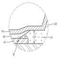
도 2는 도 1의 A부위를 확대한 도면이다.
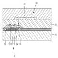
도 3a 및 도 3b는 도 1에 도시된 유기 발광 표시 장치의 제조과정을 도시한 단면도이다.1 is a cross-sectional view of an organic light emitting diode display according to an exemplary embodiment of the present invention.
FIG. 2 is an enlarged view of a portion A of FIG. 1.
3A and 3B are cross-sectional views illustrating a manufacturing process of the organic light emitting diode display illustrated in FIG. 1.
이하, 첨부된 도면들을 참조하여 본 발명의 바람직한 실시예를 상세히 설명하면 다음과 같다.Hereinafter, preferred embodiments of the present invention will be described in detail with reference to the accompanying drawings.
도 1은 본 발명의 바람직한 일 실시예에 따른 유기 발광 표시 장치를 도시한 단면도이다.1 is a cross-sectional view illustrating an organic light emitting diode display according to an exemplary embodiment of the present invention.
도 1에 도시된 바와 같이 본 실시예의 유기 발광 표시 장치는 기판(10) 상에 박막트랜지스터(30)와 유기발광소자(40)를 구비하고 있다. 참고로 도 1은 유기 발광 표시 장치 중에서 한 화소 부위를 도시한 것으로, 본 발명의 유기 발광 표시 장치는 이러한 화소가 복수개 존재한다.As shown in FIG. 1, the organic light emitting diode display according to the present exemplary embodiment includes a
먼저 상기 박막트랜지스터(30)는, 기판(10) 상에 형성된 활성층(31)과, 이 활성층(31)을 덮는 제1절연층(32)과, 제1절연층(32) 상에 형성된 게이트전극(33)과, 게이트전극(33)을 덮도록 제1절연층(32) 상에 형성된 제2절연층(34) 및, 비어홀을 통해 활성층(31)과 유기발광소자(40)의 화소전극(41)에 각각 연결된 소스드레인전극(35)을 포함한다. 따라서, 게이트전극(33)에 적정 전압이 인가되면 활성층(31)과 소스드레인전극(35)을 통해 상기 화소전극(41)으로 전류가 흐르게 된다.First, the
필요에 따라 기판(10)의 상면에는 기판(10)의 평활성과 불순 원소의 침투를 차단하기 위한버퍼층(미도시)이 더 구비될 수도 있다.If necessary, the upper surface of the
참조부호 20은 무기 절연막 또는 유기 절연막으로 형성된 패시베이션층을 나타낸다. 무기 절연막으로는 SiO2, SiNx, SiON, Al2O3, TiO2, Ta2O5, HfO2, ZrO2, BST, PZT 등이 포함되도록 할 수 있고, 유기 절연막으로는 일반 범용고분자(PMMA, PS), phenol그룹을 갖는 고분자 유도체, 아크릴계 고분자, 이미드계 고분자, 아릴에테르계 고분자, 아마이드계 고분자, 불소계고분자, p-자일렌계 고분자, 비닐알콜계 고분자 또는 이들의 블렌드 등이 포함되도록 할 수 있다. 또한, 패시베이션층(20)은 무기 절연막과 유기 절연막의 복합 적층체로도 형성될 수 있다.
이 패시베이션층(20) 상에 전술한 바와 같이 소스드레인전극(35)과 콘택된 유기발광소자(40)의 화소전극(41)이 형성된다.As described above, the
또한, 상기 패시베이션층(20) 상에는 상기 화소전극(41)을 둘러싸서 독립된 화소영역으로 구획하는 화소정의막(51)과 스페이서(52)가 일체로 형성되고, 화소전극(41) 상부로 유기발광소자(40)의 유기발광층(42) 및 대향전극(43)이 차례로 형성된다.In addition, a
여기서 유기발광소자(40)에 대해 좀 더 자세히 설명하면, 상기 유기발광소자(40)는 상기 박막트랜지스터(30)와 전기적으로 연결되어 발광이 일어나는 곳으로, 상기와 같이 박막트랜지스터(30)와 연결된 화소전극(41)과, 공통전극인 대향전극(43), 그리고 두 전극(41)(43) 사이에 개재된 유기발광층(42)을 구비한다. 따라서, 박막트랜지스터(30) 로부터 화소전극(41)에 전압이 인가되어 상기 대향전극(43)과의 사이에 적절한 전압 조건이 형성되면 유기발광층(42)에서 발광이 일어나게 된다.Here, the organic
대향전극(43)의 방향으로 화상을 구현하는 전면 발광형 구조의 경우, 상기 화소전극(41)은 반사형 전극으로 구비될 수 있다. 이를 위해 Al, Ag 등의 합금으로 구비된 반사막을 구비하도록 한다.In the case of a top emission type structure that implements an image in the direction of the
상기 화소전극(41)을 애노드 전극으로 사용할 경우, 일함수(절대치)가 높은 ITO, IZO, ZnO 등의 금속 산화물로 이루어진 층을 포함하도록 한다. 상기 화소전극(41)을 캐소드 전극으로 사용할 경우에는 Ag, Mg, Al, Pt, Pd, Au, Ni, Nd, Ir, Cr, Li, Ca 등의 일함수(절대치)가 낮은 고도전성의 금속을 사용한다. 따라서, 이 경우에는 전술한 반사막은 불필요하게 될 것이다.When the
상기 대향전극(43)은 광투과형 전극으로 구비될 수 있다. 이를 위해 Ag, Mg, Al, Pt, Pd, Au, Ni, Nd, Ir, Cr, Li, Ca 등을 박막으로 형성한 반투과 반사막을 포함하거나, ITO, IZO, ZnO 등의 광투과성 금속 산화물을 포함할 수 있다. 상기 화소전극(41)을 애노드로 할 경우, 대향전극(43)은 캐소드로, 상기 화소전극(41)을 캐소드로 할 경우, 상기 대향전극(43)은 애노드로 한다.The
상기 화소전극(41)과 대향전극(43) 사이에 개재된 유기발광층(42)은 정공 주입수송층, 발광층, 전자 주입수송층 등이 모두 또는 선택적으로 적층되어 구비될 수 있다. 다만, 발광층은 필수적으로 구비한다.The organic
여기서 상기 유기발광층(42)은 잉크젯 프린팅이나 노즐프린팅과 같은 인쇄 공정으로 형성될 수 있다. 즉, 상기 화소정의막(51)과 스페이서(52)로 구획된 화소 영역 안에 유기발광층(42)의 구성 물질인 잉크 액적을 떨어뜨리면 그 액적이 화소 영역을 매운 후 건조되면서 유기발광층(42)을 형성하게 되는 것이다.The organic
이때 액적이 인접한 다른 화소 영역을 침범하면 안 되므로 상기 화소정의막(51)과 스페이서(52)가 댐의 역할을 충분히 할 수 있어야 한다. 그런데, 이를 위해 화소정의막(51)을 제한된 공간 안에서 너무 두껍게 만들면 화소 영역을 향한 테이퍼 각도(도 2의 θ)가 너무 커지게 된다. 그렇게 되면 화소 영역과 화소정의막(51) 간의 경계를 이루는 모서리부(도 2의 B)에는 액적이 잘 매워지지 않아서 불량 화소가 될 수도 있다. 따라서, 이러한 문제가 생기지 않게 하려면 화소정의막(51)의 두께(도 2의 h)를 4000Å 이하로 얇게 하여 테이퍼 각도(도 2의 θ)를 15~30도 범위로 유지하는 것이 좋다.At this time, since the droplets must not invade other adjacent pixel areas, the
반면, 화소정의막(51)을 얇게 하면 전술한 댐의 역할을 화소정의막(51)이 혼자 수행할 수 없으므로 스페이서(52)가 꼭 형성되어야 하는데, 화소정의막(51)과 스페이서(52)를 각각의 패턴에 해당되는 마스크로 형성하게 되면 두 번의 마스크 공정이 필요하므로 제조과정이 상당히 복잡해진다.On the other hand, when the
따라서, 이러한 조건들을 만족시키기 위해 본 실시예에서는 도 3b에 도시된 바와 같은 하프톤 마스크(100)를 사용한다.Therefore, in order to satisfy these conditions, the present embodiment uses the
이하에는 이 하프톤 마스크(100)를 사용한 화소정의막(51)과 스페이서(52)의 제조과정에 대해 설명한다.Hereinafter, a manufacturing process of the
일단, 도 3a에 도시된 바와 같이 화소전극(41) 위에 화소정의막(51)과 스페이서(52)가 형성될 유기절연물질층(50)을 형성한다. 유기절연물질로는 폴리이미드 등이 사용될 수 있다.First, as shown in FIG. 3A, the organic insulating
그리고는 도 3b와 같이 상기 하프톤 마스크(100)를 유기절연물질층(50) 위에 대고 노광 작업을 수행한다. 이때 이 하프톤 마스크(100)에 의해 화소전극(41)이 배치된 화소 영역과, 화소정의막(51)이 형성될 영역 및 스페이서(52)가 형성될 영역이 서로 다른 정도로 노광이 진행된다.Then, the
즉, 상기 하프톤 마스크(100)는 광을 100% 투과시키는 광투과부(110)와, 100% 차단하는(광투과율이 0%인) 광차단부(130), 그리고 광을 중간 정도로 투과시키는 반투과부(120)를 구비하고 있다. 상기 광투과부(110)가 상기 화소전극(41) 영역에, 상기 반투과부(120)가 화소정의막(51) 영역에, 상기 광차단부(130)가 스페이서(52) 영역에 각각 대응되도록 하프톤 마스크(100)를 배치하고 노광을 진행한다.That is, the
그러면, 광투과부(110)에 의해 100% 노광된 부위는 다음의 식각 공정에서 유기절연물질층(50)이 완전히 제거되어 화소전극(41)이 노출되며, 광차단부(130)에 의해 100% 빛이 차단된 부위는 유기절연물질층(50)이 그대로 남아서 스페이서(52)를 형성하게 된다. 그리고, 광이 중간 정도로 투과된 반투과부(120) 영역에는 유기절연물질층(50)이 중간 정도 남아서 화소정의막(51)을 형성하게 된다. 따라서, 한번의 마스크 공정으로 화소정의막(51)과 스페이서(52)를 동시에 일체로 형성하게 되므로, 기존에 두 번의 마스크 공정을 사용하던 번거로움을 해결할 수 있다.Then, the portion exposed 100% by the
여기서 상기 화소정의막(51)을 형성하는 상기 반투과부(120)는 광투과율이 40~70% 범위인 것이 적합하다. 이 범위에서 노광시키면 화소정의막(51)의 두께(도 2의 h)는 스페이서(52) 두께의 절반 이하 수준인 4000Å 이하로 남게 되고, 테이퍼 각도(도 2의 θ)는 15~30도의 범위로 만들어지게 된다.In this case, the
또한, 노광 시에는 노광면인 상기 유기절연물질층(50)이 표면에 광이 초점이 정확히 맺히지 않도록 의도적으로 초점을 이동시키는 디포커싱(defocusing)으로 진행할 수 있다. 즉, 광의 초점이 노광면에서 약 10~15μm 정도 떨어져서 맺히게 디포커싱시키면, 하프톤 마스크(100)의 광투과부(110)나 반투과부(120)를 통해 노광되는 영역의 경계부가 흐릿해진다. 그러면 노광 후 식각에 의해 형성된 화소 영역의 경계도 완만한 경사로 형성되어 결국 테이퍼 각도(도 2의 θ)를 완만하게 형성하는데 도움이 된다. 따라서, 이렇게 화소정의막(51)의 테이퍼 각도를 30도 이하로 작게 만들면, 화소 영역에 유기발광층(42)의 잉크 액적이 고르게 잘 매워질 수 있으므로 불량 화소가 생길 우려도 해소할 수 있다. 그러나, 각도가 너무 작으면 화소의 크기를 결정하는 화소정의막(51)의 기능이 상실될 수도 있으므로, 15도 이상은 유지하는 것이 바람직하다.In addition, during exposure, the organic insulating
이와 같이 화소정의막(51)과 스페이서(52)를 형성한 다음에, 잉크 액적을 화소 영역에 투하하여 유기발광층(42)을 형성하고, 그 위에 공통전극인 대향전극(43)을 형성하면 도 1에 도시된 바와 같은 유기 발광 표시 장치가 만들어진다.After forming the
도면으로 도시하지는 않았지만 상기 대향전극(43) 위로는 보호층이 더 형성될 수 있고, 글라스 등에 의한 밀봉이 이루어질 수 있다.Although not shown in the drawings, a protective layer may be further formed on the
이상에서 설명한 바와 같이 본 발명의 실시예에 따른 유기 발광 표시 장치 및 제조방법에서는 화소정의막과 스페이서를 하프톤 마스크를 이용한 단일 마스크 공정으로 형성하므로, 제조 공정을 간소화할 수 있으며, 또한 화소정의막의 테이퍼 각도를 작게 만들어서 균일한 유기발광층을 형성할 수도 있다.As described above, the organic light emitting diode display and the manufacturing method according to the exemplary embodiment of the present invention form the pixel definition layer and the spacer in a single mask process using a halftone mask, thereby simplifying the manufacturing process and further improving the pixel definition layer. The taper angle can be made small to form a uniform organic light emitting layer.
본 발명은 첨부된 도면에 도시된 일 실시예를 참고로 설명되었으나 이는 예시적인 것에 불과하며, 당해 기술분야에서 통상의 지식을 가진 자라면 이로부터 다양한 변형 및 균등한 타 실시예가 가능하다는 점을 이해할 수 있을 것이다. 따라서 본 발명의 진정한 보호 범위는 첨부된 청구 범위에 의해서만 정해져야 할 것이다.Although the present invention has been described with reference to one embodiment shown in the accompanying drawings, this is merely exemplary, and it will be understood by those skilled in the art that various modifications and equivalent other embodiments are possible. Could be. Therefore, the true scope of protection of the present invention should be defined only by the appended claims.
10...기판20...패시베이션층
30...박막트랜지스터31...활성층
32...제1절연층33...게이트전극
34...제2절연층35...소스드레인전극
40...유기발광소자41...화소전극
43...유기발광층43...대향전극
50...유기절연물질층51...화소정의막
52...스페이서100...하프톤 마스크
110...광투과부 120...반투과부
130...광차단부10 ...
30 ...
32 first insulating
34 second insulating
40 organic
43 organic
50 ...
52
110 ... light transmitting
130 ... light shield
Claims (7)
Translated fromKorean광차단부와 반투과부 및 광투과부를 가진 하프톤 마스크를 준비하는 단계;
상기 하프톤 마스크를 상기 유기절연물질층 위에 설치하여, 상기 광투과부 영역에 상기 화소전극이, 상기 반투과부 영역에 상기 화소전극을 둘러싸는 화소정의막이, 상기 광차단부 영역에 상기 화소정의막 위에 돌출되는 스페이서가 각각 대응되도록 노광시키는 단계;
상기 노광된 유기절연물질층을 식각하여, 상기 화소전극 상의 화소 영역을 상기 화소정의막과 상기 스페이서가 둘러싼 구조로 만드는 단계를 포함하며,
상기 광차단부의 광투과율은 0%, 상기 반투과부의 광투과율은 40~70%, 상기 광투과부의 광투과율은 100%이고,
상기 노광 단계는 광의 초점이 노광면에 맞지 않게 조정하는 디포커싱으로 진행되는 것을 특징으로 하는 유기 발광 표시 장치 제조방법.Forming an organic insulating material layer on the pixel electrode;
Preparing a halftone mask having a light blocking portion, a transflective portion, and a light transmissive portion;
The halftone mask is disposed on the organic insulating material layer so that the pixel electrode is disposed in the light transmissive region, and the pixel definition layer surrounds the pixel electrode in the transflective region. Exposing the protruding spacers to correspond respectively;
Etching the exposed organic insulating material layer to form a structure in which the pixel area on the pixel electrode is surrounded by the pixel definition layer and the spacer,
The light transmittance of the light blocking portion is 0%, the light transmittance of the transflective portion is 40 to 70%, the light transmittance of the light transmitting portion is 100%,
And the exposing step is performed by defocusing so that the focus of light does not match the exposure surface.
상기 디포커싱은 상기 광의 초점이 노광면에서 10~15μm 떨어져서 맺히게 하는 것을 특징으로 하는 유기 발광 표시 장치 제조방법.The method of claim 3,
The defocusing method of manufacturing an organic light emitting display device, characterized in that the focus of the light is condensed 10 ~ 15μm away from the exposure surface.
상기 화소정의막의 상기 화소 영역을 향한 테이퍼 각도를 15~30도 범위로 형성하는 것을 특징으로 하는 유기 발광 표시 장치 제조방법.The method of claim 3,
And a taper angle of the pixel definition layer toward the pixel area in a range of 15 to 30 degrees.
상기 화소정의막의 두께는 4000Å 이하로 형성하는 것을 특징으로 하는 유기 발광 표시 장치 제조방법.The method of claim 3,
The pixel definition layer has a thickness of 4000 kPa or less.
Priority Applications (4)
| Application Number | Priority Date | Filing Date | Title |
|---|---|---|---|
| KR1020100013846AKR101084193B1 (en) | 2010-02-16 | 2010-02-16 | OLED display and manufacturing method thereof |
| JP2010153805AJP5079851B2 (en) | 2010-02-16 | 2010-07-06 | Manufacturing method of organic light emitting display device |
| US13/022,530US8835205B2 (en) | 2010-02-16 | 2011-02-07 | Organic light-emitting display device and method of manufacturing the same |
| CN201110039435.3ACN102163617B (en) | 2010-02-16 | 2011-02-15 | Method for manufacturing organic light-emitting display device |
Applications Claiming Priority (1)
| Application Number | Priority Date | Filing Date | Title |
|---|---|---|---|
| KR1020100013846AKR101084193B1 (en) | 2010-02-16 | 2010-02-16 | OLED display and manufacturing method thereof |
Publications (2)
| Publication Number | Publication Date |
|---|---|
| KR20110094460A KR20110094460A (en) | 2011-08-24 |
| KR101084193B1true KR101084193B1 (en) | 2011-11-17 |
Family
ID=44369012
Family Applications (1)
| Application Number | Title | Priority Date | Filing Date |
|---|---|---|---|
| KR1020100013846AActiveKR101084193B1 (en) | 2010-02-16 | 2010-02-16 | OLED display and manufacturing method thereof |
Country Status (4)
| Country | Link |
|---|---|
| US (1) | US8835205B2 (en) |
| JP (1) | JP5079851B2 (en) |
| KR (1) | KR101084193B1 (en) |
| CN (1) | CN102163617B (en) |
Cited By (2)
| Publication number | Priority date | Publication date | Assignee | Title |
|---|---|---|---|---|
| KR20150087997A (en)* | 2014-01-23 | 2015-07-31 | 삼성디스플레이 주식회사 | Display panel and display device |
| US10896940B2 (en) | 2019-02-22 | 2021-01-19 | Samsung Display Co., Ltd. | Transparent display device and method of manufacturing the same |
Families Citing this family (33)
| Publication number | Priority date | Publication date | Assignee | Title |
|---|---|---|---|---|
| JP6083122B2 (en)* | 2012-03-27 | 2017-02-22 | 凸版印刷株式会社 | Organic electroluminescence device and method for manufacturing the same |
| KR101924606B1 (en)* | 2012-04-27 | 2018-12-04 | 삼성디스플레이 주식회사 | Organic light emitting display device and the fabrication method thereof |
| CN104396345B (en)* | 2012-06-20 | 2016-08-24 | 日本先锋公司 | Organic Electroluminescent Devices |
| KR101955621B1 (en) | 2012-09-21 | 2019-05-31 | 삼성디스플레이 주식회사 | Organic light emitting display panel and fabricating method for the same |
| KR20140058745A (en) | 2012-11-05 | 2014-05-15 | 삼성디스플레이 주식회사 | Organic light emitting diode display and manufacturing method thereof |
| KR20140070142A (en) | 2012-11-30 | 2014-06-10 | 삼성디스플레이 주식회사 | Organic light emitting display and manufacturing method thereof |
| KR102030799B1 (en)* | 2013-03-11 | 2019-10-11 | 삼성디스플레이 주식회사 | Organic luminescence emitting display device |
| KR102054850B1 (en) | 2013-05-30 | 2019-12-12 | 삼성디스플레이 주식회사 | Organic light emitting display apparatus and method of manufacturing the same |
| KR102080008B1 (en)* | 2013-07-12 | 2020-02-24 | 삼성디스플레이 주식회사 | Organic luminescence emitting display device and method for manufacturing the same |
| CN103715140B (en)* | 2013-10-12 | 2016-03-16 | 深圳市华星光电技术有限公司 | A kind of method avoiding metallic circuit short circuit in OLED display device |
| KR102260991B1 (en)* | 2014-02-14 | 2021-06-07 | 삼성디스플레이 주식회사 | Display panel and method of manufacturing the same |
| JP6371094B2 (en) | 2014-03-31 | 2018-08-08 | 株式会社ジャパンディスプレイ | Organic EL display device |
| KR101664007B1 (en)* | 2014-12-31 | 2016-10-11 | 엘지디스플레이 주식회사 | Organic light emitting device and manufacturing method thereof |
| KR102300404B1 (en)* | 2015-01-14 | 2021-09-09 | 삼성디스플레이 주식회사 | Organic light emitting diode display |
| CN104716024A (en)* | 2015-03-04 | 2015-06-17 | 山东大学 | Method for improving thin-film semiconductor transistor electrical property |
| KR102430819B1 (en) | 2015-08-19 | 2022-08-10 | 삼성디스플레이 주식회사 | Organic light emitting display apparatus and method for manufacturing the same |
| KR102516054B1 (en) | 2015-11-13 | 2023-03-31 | 삼성디스플레이 주식회사 | Organic light emitting display apparatus and method for manufacturing the same |
| KR102467353B1 (en)* | 2015-11-27 | 2022-11-15 | 삼성디스플레이 주식회사 | Display substrate, method of manufacturing a display substrate, and display device including a display substrate |
| KR20170080459A (en)* | 2015-12-30 | 2017-07-10 | 엘지디스플레이 주식회사 | Organic light emitting diode display device |
| CN111554701B (en)* | 2016-05-20 | 2023-05-16 | 群创光电股份有限公司 | Display apparatus |
| KR102735982B1 (en)* | 2016-06-30 | 2024-11-28 | 엘지디스플레이 주식회사 | Organic light emitting display device |
| CN106067478A (en)* | 2016-08-08 | 2016-11-02 | 深圳市华星光电技术有限公司 | Pixel defines the manufacture method of layer and the manufacture method of OLED |
| KR102710997B1 (en)* | 2016-12-02 | 2024-09-27 | 삼성디스플레이 주식회사 | Organic light emitting display device and manufacturing method thereof |
| CN207052608U (en)* | 2017-08-24 | 2018-02-27 | 京东方科技集团股份有限公司 | A kind of display base plate and display device |
| CN107393939B (en)* | 2017-08-30 | 2020-04-17 | 京东方科技集团股份有限公司 | Pixel defining layer and manufacturing method thereof, display panel and manufacturing method thereof, and display device |
| CN107910353A (en)* | 2017-11-23 | 2018-04-13 | 京东方科技集团股份有限公司 | Organic light emitting apparatus and preparation method thereof |
| KR102490894B1 (en)* | 2018-02-08 | 2023-01-25 | 삼성디스플레이 주식회사 | Organic light emitting display apparatus |
| KR102724703B1 (en)* | 2018-10-23 | 2024-11-01 | 삼성디스플레이 주식회사 | Display apparatus and Mask for manufacturing display apparatus |
| CN208753326U (en)* | 2018-11-05 | 2019-04-16 | 北京京东方技术开发有限公司 | Display substrate and display device |
| KR102811393B1 (en)* | 2019-05-30 | 2025-05-23 | 삼성디스플레이 주식회사 | Display device and manufacturing method for display device |
| US10964764B2 (en)* | 2019-07-01 | 2021-03-30 | Shenzhen China Star Optoelectronics Semiconductor Display Technology Co., Ltd. | Display panel and method of manufacturing thereof |
| CN110335889A (en)* | 2019-07-01 | 2019-10-15 | 深圳市华星光电半导体显示技术有限公司 | Display panel and preparation method thereof |
| KR102216680B1 (en)* | 2020-02-12 | 2021-02-18 | 삼성디스플레이 주식회사 | Organic luminescence emitting display device |
Citations (2)
| Publication number | Priority date | Publication date | Assignee | Title |
|---|---|---|---|---|
| KR100833773B1 (en)* | 2007-06-20 | 2008-05-29 | 삼성에스디아이 주식회사 | Organic electroluminescent display and manufacturing method thereof |
| WO2009147838A1 (en) | 2008-06-06 | 2009-12-10 | パナソニック株式会社 | Organic el display panel and manufacturing method thereof |
Family Cites Families (21)
| Publication number | Priority date | Publication date | Assignee | Title |
|---|---|---|---|---|
| JP2004165067A (en) | 2002-11-14 | 2004-06-10 | Sanyo Electric Co Ltd | Organic electroluminescent panel |
| US7227306B2 (en)* | 2003-08-28 | 2007-06-05 | Samsung Sdi Co., Ltd. | Organic electroluminescence display having recessed electrode structure |
| EP1523043B1 (en)* | 2003-10-06 | 2011-12-28 | Semiconductor Energy Laboratory Co., Ltd. | Optical sensor and method for manufacturing the same |
| KR100741962B1 (en)* | 2003-11-26 | 2007-07-23 | 삼성에스디아이 주식회사 | Flat Panel Display |
| KR100611159B1 (en)* | 2003-11-29 | 2006-08-09 | 삼성에스디아이 주식회사 | Organic light emitting display device |
| JP2006004743A (en)* | 2004-06-17 | 2006-01-05 | Toshiba Matsushita Display Technology Co Ltd | Display device and its manufacturing method |
| US7554265B2 (en)* | 2004-06-25 | 2009-06-30 | Semiconductor Energy Laboratory Co., Ltd. | Display device |
| KR100699996B1 (en)* | 2004-09-02 | 2007-03-26 | 삼성에스디아이 주식회사 | Organic light emitting display device including pad for circuit measurement and manufacturing method |
| JP4876415B2 (en) | 2005-03-29 | 2012-02-15 | セイコーエプソン株式会社 | Organic EL device manufacturing method, device manufacturing method |
| JP2007044582A (en) | 2005-08-08 | 2007-02-22 | Seiko Epson Corp | Surface treatment method, electro-optical device manufacturing method, and electro-optical device |
| JP2007188862A (en)* | 2005-12-13 | 2007-07-26 | Canon Inc | Organic EL light emitting device and method for manufacturing the same |
| JP2007207962A (en)* | 2006-02-01 | 2007-08-16 | Seiko Epson Corp | LIGHT EMITTING DEVICE, LIGHT EMITTING DEVICE MANUFACTURING METHOD, AND ELECTRONIC DEVICE |
| KR20080029279A (en) | 2006-09-28 | 2008-04-03 | 삼성전자주식회사 | Thin film transistor array panel and manufacturing method thereof |
| KR101319306B1 (en) | 2006-12-20 | 2013-10-16 | 엘지디스플레이 주식회사 | Method of manufacturing Organic Electroluminescent Device |
| JP2008210653A (en)* | 2007-02-27 | 2008-09-11 | Canon Inc | Organic EL device |
| KR100838090B1 (en) | 2007-08-09 | 2008-06-13 | 삼성에스디아이 주식회사 | OLED display and manufacturing method thereof |
| KR100924137B1 (en) | 2008-01-31 | 2009-10-29 | 삼성모바일디스플레이주식회사 | Organic light emitting display device and manufacturing method |
| KR100964229B1 (en)* | 2008-08-19 | 2010-06-17 | 삼성모바일디스플레이주식회사 | Organic light emitting display and manufacturing method thereof |
| JP4884452B2 (en)* | 2008-12-09 | 2012-02-29 | 三洋電機株式会社 | Method for manufacturing organic electroluminescent panel |
| KR101073293B1 (en)* | 2009-06-25 | 2011-10-12 | 삼성모바일디스플레이주식회사 | Halftone mask and manufacturing method thereof and method for forming film using the same |
| KR20120106192A (en)* | 2011-03-18 | 2012-09-26 | 삼성디스플레이 주식회사 | Organic light emitting diode device and method of manufacturing the same |
- 2010
- 2010-02-16KRKR1020100013846Apatent/KR101084193B1/enactiveActive
- 2010-07-06JPJP2010153805Apatent/JP5079851B2/enactiveActive
- 2011
- 2011-02-07USUS13/022,530patent/US8835205B2/enactiveActive
- 2011-02-15CNCN201110039435.3Apatent/CN102163617B/enactiveActive
Patent Citations (2)
| Publication number | Priority date | Publication date | Assignee | Title |
|---|---|---|---|---|
| KR100833773B1 (en)* | 2007-06-20 | 2008-05-29 | 삼성에스디아이 주식회사 | Organic electroluminescent display and manufacturing method thereof |
| WO2009147838A1 (en) | 2008-06-06 | 2009-12-10 | パナソニック株式会社 | Organic el display panel and manufacturing method thereof |
Cited By (4)
| Publication number | Priority date | Publication date | Assignee | Title |
|---|---|---|---|---|
| KR20150087997A (en)* | 2014-01-23 | 2015-07-31 | 삼성디스플레이 주식회사 | Display panel and display device |
| KR101958392B1 (en)* | 2014-01-23 | 2019-07-05 | 삼성디스플레이 주식회사 | Display panel and display device |
| US10896940B2 (en) | 2019-02-22 | 2021-01-19 | Samsung Display Co., Ltd. | Transparent display device and method of manufacturing the same |
| US11581377B2 (en) | 2019-02-22 | 2023-02-14 | Samsung Display Co., Ltd. | Method of manufacturing transparent display device |
Also Published As
| Publication number | Publication date |
|---|---|
| CN102163617A (en) | 2011-08-24 |
| US8835205B2 (en) | 2014-09-16 |
| CN102163617B (en) | 2015-06-17 |
| JP2011171268A (en) | 2011-09-01 |
| JP5079851B2 (en) | 2012-11-21 |
| US20110198596A1 (en) | 2011-08-18 |
| KR20110094460A (en) | 2011-08-24 |
Similar Documents
| Publication | Publication Date | Title |
|---|---|---|
| KR101084193B1 (en) | OLED display and manufacturing method thereof | |
| KR101748842B1 (en) | An organic light emitting display device and the manufacturing method thereof | |
| KR102446425B1 (en) | Display device and method of manufacturing display device | |
| KR102538983B1 (en) | Organic light emitting display device | |
| KR102516054B1 (en) | Organic light emitting display apparatus and method for manufacturing the same | |
| US11094904B2 (en) | Light emitting display apparatus for improving light extracting efficiency | |
| CN110349996B (en) | Light emitting device, display apparatus, and image pickup apparatus | |
| KR100833772B1 (en) | Organic electroluminescent display and manufacturing method thereof | |
| US7126275B2 (en) | System and methods for providing organic electro-luminescence elements | |
| JP5475570B2 (en) | Organic light-emitting display device | |
| KR100462861B1 (en) | Flat Panel Display with Black Matrix and Fabrication Method thereof | |
| JP6331276B2 (en) | Electro-optical device, method of manufacturing electro-optical device, and electronic apparatus | |
| US10090484B1 (en) | Organic light-emitting display apparatus and method of manufacturing the same | |
| KR102261610B1 (en) | Organic light emitting display device | |
| WO2016056364A1 (en) | Display device, display device manufacturing method, and electronic equipment | |
| US11335883B2 (en) | Organic light-emitting diode display substrate with a protection layer and manufacturing method thereof, and display device | |
| JP2008177169A (en) | Organic electroluminescent display device and manufacturing method thereof | |
| US20140319475A1 (en) | Organic light emitting diode display and manufacturing method thereof | |
| CN109037277B (en) | Preparation method of OLED display panel, OLED display panel and display device | |
| KR20040103062A (en) | OLED and fabrication method thereof | |
| US20210202626A1 (en) | Display device and method of manufacturing the same | |
| US20160233284A1 (en) | Organic el device and electronic apparatus | |
| KR20190034902A (en) | Display device having an auxiliary electrode | |
| CN113133330B (en) | Display panel and manufacturing method thereof, and display device | |
| CN110767845A (en) | Display panel and manufacturing method thereof |
Legal Events
| Date | Code | Title | Description |
|---|---|---|---|
| A201 | Request for examination | ||
| PA0109 | Patent application | Patent event code:PA01091R01D Comment text:Patent Application Patent event date:20100216 | |
| PA0201 | Request for examination | ||
| E902 | Notification of reason for refusal | ||
| PE0902 | Notice of grounds for rejection | Comment text:Notification of reason for refusal Patent event date:20110517 Patent event code:PE09021S01D | |
| PG1501 | Laying open of application | ||
| E701 | Decision to grant or registration of patent right | ||
| PE0701 | Decision of registration | Patent event code:PE07011S01D Comment text:Decision to Grant Registration Patent event date:20111031 | |
| GRNT | Written decision to grant | ||
| PR0701 | Registration of establishment | Comment text:Registration of Establishment Patent event date:20111110 Patent event code:PR07011E01D | |
| PR1002 | Payment of registration fee | Payment date:20111111 End annual number:3 Start annual number:1 | |
| PG1601 | Publication of registration | ||
| FPAY | Annual fee payment | Payment date:20141030 Year of fee payment:4 | |
| PR1001 | Payment of annual fee | Payment date:20141030 Start annual number:4 End annual number:4 | |
| FPAY | Annual fee payment | Payment date:20151030 Year of fee payment:5 | |
| PR1001 | Payment of annual fee | Payment date:20151030 Start annual number:5 End annual number:5 | |
| FPAY | Annual fee payment | Payment date:20171101 Year of fee payment:7 | |
| PR1001 | Payment of annual fee | Payment date:20171101 Start annual number:7 End annual number:7 | |
| FPAY | Annual fee payment | Payment date:20181101 Year of fee payment:8 | |
| PR1001 | Payment of annual fee | Payment date:20181101 Start annual number:8 End annual number:8 | |
| FPAY | Annual fee payment | Payment date:20191028 Year of fee payment:9 | |
| PR1001 | Payment of annual fee | Payment date:20191028 Start annual number:9 End annual number:9 | |
| PR1001 | Payment of annual fee | Payment date:20201102 Start annual number:10 End annual number:10 | |
| PR1001 | Payment of annual fee | Payment date:20211027 Start annual number:11 End annual number:11 | |
| PR1001 | Payment of annual fee | Payment date:20221025 Start annual number:12 End annual number:12 | |
| PR1001 | Payment of annual fee | Payment date:20231023 Start annual number:13 End annual number:13 | |
| PR1001 | Payment of annual fee | Payment date:20241022 Start annual number:14 End annual number:14 |