KR101083395B1 - Dust Collecting Blade of Cleaning Robot and Cleaning Robot therewith - Google Patents
Dust Collecting Blade of Cleaning Robot and Cleaning Robot therewithDownload PDFInfo
- Publication number
- KR101083395B1 KR101083395B1KR1020100028147AKR20100028147AKR101083395B1KR 101083395 B1KR101083395 B1KR 101083395B1KR 1020100028147 AKR1020100028147 AKR 1020100028147AKR 20100028147 AKR20100028147 AKR 20100028147AKR 101083395 B1KR101083395 B1KR 101083395B1
- Authority
- KR
- South Korea
- Prior art keywords
- dust
- dust collecting
- cleaning robot
- collecting blade
- hinge
- Prior art date
- Legal status (The legal status is an assumption and is not a legal conclusion. Google has not performed a legal analysis and makes no representation as to the accuracy of the status listed.)
- Active
Links
- 239000000428dustSubstances0.000titleclaimsabstractdescription137
- 238000004140cleaningMethods0.000titleclaimsabstractdescription41
- 239000002699waste materialSubstances0.000claimsabstractdescription8
- 238000003780insertionMethods0.000claimsdescription31
- 230000037431insertionEffects0.000claimsdescription31
- 230000002265preventionEffects0.000claimsdescription13
- 238000000926separation methodMethods0.000claimsdescription9
- 238000000034methodMethods0.000claims8
- 238000005452bendingMethods0.000description2
- 238000005516engineering processMethods0.000description1
- 238000011086high cleaningMethods0.000description1
- 238000012423maintenanceMethods0.000description1
- 238000012986modificationMethods0.000description1
- 230000004048modificationEffects0.000description1
- 230000002093peripheral effectEffects0.000description1
- 238000006467substitution reactionMethods0.000description1
Images


Classifications
- A—HUMAN NECESSITIES
- A47—FURNITURE; DOMESTIC ARTICLES OR APPLIANCES; COFFEE MILLS; SPICE MILLS; SUCTION CLEANERS IN GENERAL
- A47L—DOMESTIC WASHING OR CLEANING; SUCTION CLEANERS IN GENERAL
- A47L11/00—Machines for cleaning floors, carpets, furniture, walls, or wall coverings
- A47L11/32—Carpet-sweepers
- A47L11/33—Carpet-sweepers having means for storing dirt
- A—HUMAN NECESSITIES
- A47—FURNITURE; DOMESTIC ARTICLES OR APPLIANCES; COFFEE MILLS; SPICE MILLS; SUCTION CLEANERS IN GENERAL
- A47L—DOMESTIC WASHING OR CLEANING; SUCTION CLEANERS IN GENERAL
- A47L11/00—Machines for cleaning floors, carpets, furniture, walls, or wall coverings
- A47L11/40—Parts or details of machines not provided for in groups A47L11/02 - A47L11/38, or not restricted to one of these groups, e.g. handles, arrangements of switches, skirts, buffers, levers
- A47L11/4013—Contaminants collecting devices, i.e. hoppers, tanks or the like
- A—HUMAN NECESSITIES
- A47—FURNITURE; DOMESTIC ARTICLES OR APPLIANCES; COFFEE MILLS; SPICE MILLS; SUCTION CLEANERS IN GENERAL
- A47L—DOMESTIC WASHING OR CLEANING; SUCTION CLEANERS IN GENERAL
- A47L11/00—Machines for cleaning floors, carpets, furniture, walls, or wall coverings
- A47L11/40—Parts or details of machines not provided for in groups A47L11/02 - A47L11/38, or not restricted to one of these groups, e.g. handles, arrangements of switches, skirts, buffers, levers
- A47L11/4036—Parts or details of the surface treating tools
- A47L11/4044—Vacuuming or pick-up tools; Squeegees
- A—HUMAN NECESSITIES
- A47—FURNITURE; DOMESTIC ARTICLES OR APPLIANCES; COFFEE MILLS; SPICE MILLS; SUCTION CLEANERS IN GENERAL
- A47L—DOMESTIC WASHING OR CLEANING; SUCTION CLEANERS IN GENERAL
- A47L2201/00—Robotic cleaning machines, i.e. with automatic control of the travelling movement or the cleaning operation
Landscapes
- Electric Vacuum Cleaner (AREA)
- Nozzles For Electric Vacuum Cleaners (AREA)
- Manipulator (AREA)
Abstract
Translated fromKoreanDescription
Translated fromKorean본 발명은 청소 로봇의 집진 블레이드 구조 및 이를 구비한 청소 로봇에 관한 것이다. 더욱 상세하게는 브러쉬의 후방으로 흐르거나 튀는 먼지를 받아서 먼지통 내부로 유입시키기 위한 청소 로봇의 집진 블레이드의 형상 및 장착구조와 이러한 집진 블레이드를 구비한 청소 로봇에 관한 것이다.The present invention relates to a dust collecting blade structure of the cleaning robot and a cleaning robot having the same. More particularly, the present invention relates to a shape and mounting structure of a dust collecting blade of a cleaning robot for receiving dust flowing or splashing to the rear of a brush and flowing it into the dust container, and a cleaning robot having the dust collecting blade.
일반적으로 로봇(robot)이란 어떤 작업이나 조작을 자동적으로 하는 기계 장치를 말한다. 이러한 로봇은 산업용 또는 의료용으로 사용되거나 인간이 활동하기 어려운 극지에서 인간을 대신하여 위험한 작업을 수행하는 데 이용되기도 한다.In general, a robot is a mechanical device that automatically performs a task or operation. Such robots can be used for industrial or medical purposes or to perform dangerous tasks on behalf of humans in polar regions where humans are difficult to operate.
로봇 기술이 발전됨에 따라 최근에는 가정에서 이용되는 로봇이 등장하기도 하였는데 이러한 가정용 로봇 중 가장 대표적인 것이 바로 청소용 로봇이다.Recently, robots used in homes have appeared as robot technology has been developed. The most representative of these household robots is a cleaning robot.
현재 청소용 로봇은 각종 센서와 네비게이션(navigation) 기능을 구비하여 자신의 위치를 파악하고 방의 경계를 인식하여 방의 구석구석을 빈틈없이 청소하는 것이 가능하며, 청소를 위한 별도의 명령을 내리지 않아도 스스로 청소를 시작 및 종료할 수 있는 정도의 수준에까지 이르렀다.Currently, the cleaning robot is equipped with various sensors and navigation functions to identify its location and recognize the boundary of the room so that every corner of the room can be cleaned without a separate instruction. It has reached a level that can be started and stopped.
청소용 로봇의 청소효율을 향상시키기 위한 노력은 점점 더 가중되고 있으며, 이러한 노력의 결과로 인해 더욱 진보된 청소용 로봇들이 개발되고 있는 추세에 있다.Efforts to improve the cleaning efficiency of the cleaning robots are getting more and more, and as a result of these efforts, more advanced cleaning robots are being developed.
본 출원인은 상기한 청소용 로봇의 개발추세에 따라 쓰레기의 집진 성능을 더욱 향상시키면서도 유지보수가 용이한 집진 블레이드 구조와 상기 집진 블레이드를 구비한 청소 로봇을 제공하는 것을 그 목적으로 한다.The present inventors aim to provide a dust collecting blade structure and a cleaning robot having the dust collecting blade, which is easy to maintain while further improving dust collecting performance according to the development trend of the cleaning robot.
상기한 목적을 달성하기 위해 본 발명은 청소 로봇에 구비되는 먼지통의 유입구 전방에 장착되어 상기 먼지통 내부로 쓰레기가 유입되도록 가이드하는 집진 블레이드 구조에 있어서, 후면에 횡방향으로 형성되는 복수 개의 지지돌기를 구비하여 복원력을 향상시킨 집진 블레이드를 포함하는 것을 특징으로 하는 청소 로봇의 집진 블레이드 구조를 제공한다.In order to achieve the above object, the present invention is a dust collecting blade structure which is mounted to the front of the inlet of the dust container provided in the cleaning robot to guide the inflow of garbage into the dust container, a plurality of support projections formed in the transverse direction on the rear It provides a dust collecting blade structure of the cleaning robot, characterized in that it comprises a dust collecting blade to improve the restoring force.
상기 집진 블레이드 구조는 상기 먼지통의 일측에 탈착되도록 일단에 후크가 형성된 후크부; 및 상기 먼지통의 타측에 힌지결합되어 회동되는 회동부를 더 포함하는 것을 특징으로 한다.The dust collecting blade structure has a hook portion formed at one end to be detached to one side of the dust container; And a rotating part hinged to the other side of the dust container and rotated.
여기서, 상기 복수 개의 지지돌기는 상기 집진 블레이드의 하단에 가깝게 배치되는 것일수록 직경이 작게 형성될 수 있다.Here, the plurality of support protrusions may be formed to have a smaller diameter as they are disposed closer to the lower end of the dust collecting blade.
또한, 상기 회동부는 상기 먼지통에 형성되는 힌지에 결합 및 분리가 가능하도록 'c'자 형태로 형성되는 힌지 삽입구를 구비하는 것을 특징으로 한다.In addition, the pivoting portion is characterized in that it comprises a hinge insertion port formed in the 'c' shape to be coupled to and separated from the hinge formed in the dust container.
한편, 본 발명은 전면에 형성되는 유입구를 통해 유입된 쓰레기를 수거하는 먼지통; 및 상기 유입구의 전방에 장착되어 상기 먼지통 내부로 쓰레기가 유입되도록 가이드하고, 후면에 횡방향으로 형성되는 복수 개의 지지돌기를 구비하는 집진 블레이드를 포함하는 것을 특징으로 하는 청소 로봇을 제공한다.On the other hand, the present invention is a dust container for collecting the waste introduced through the inlet formed on the front; And a dust collecting blade mounted at the front of the inlet to guide the garbage into the dust container, and having a dust collecting blade having a plurality of supporting protrusions formed in the transverse direction at the rear surface thereof.
여기서, 상기 먼지통은 일측에 요홈의 형태로 형성되는 후크 삽입홈을 구비하고, 타측에는 수직방향으로 돌출형성되는 힌지를 구비하며, 상기 집진 블레이드는 상기 후크 삽입홈에 탈착되는 후크가 형성된 후크부와, 상기 힌지에 결합되어 회동되는 회동부를 구비하는 것을 특징으로 한다.Here, the dust container is provided with a hook insertion groove formed in the form of a groove on one side, the other side has a hinge formed to project in the vertical direction, the dust collecting blade is a hook portion formed with a hook detachable to the hook insertion groove; It is characterized in that it comprises a pivoting portion coupled to the hinge is rotated.
또한, 상기 복수 개의 지지돌기는 상기 집진 블레이드의 하단에 가깝게 배치되는 것일수록 직경이 작게 형성될 수 있다.In addition, the plurality of support protrusions may be formed to have a smaller diameter as they are disposed closer to the lower end of the dust collecting blade.
또한, 상기 회동부는 상기 먼지통에 형성되는 힌지에 결합 및 분리가 가능하도록 'c'자 형태로 형성되는 힌지 삽입구를 구비하는 것을 특징으로 한다.In addition, the pivoting portion is characterized in that it comprises a hinge insertion port formed in the 'c' shape to be coupled to and separated from the hinge formed in the dust container.
또한, 상기 먼지통은 상기 힌지 삽입구가 상기 힌지에 결합된 상태에서 상기 힌지 삽입구의 외주면을 감싸도록 형성되는 분리 방지부를 구비하고, 상기 힌지 삽입구는 상기 분리 방지부와의 간섭을 피해 미리 정해진 각도만큼 회동시킨 후 분리되도록 하는 것을 특징으로 한다.In addition, the dust container has a separation prevention portion formed to surround the outer peripheral surface of the hinge insertion hole in a state in which the hinge insertion hole is coupled to the hinge, the hinge insertion hole is rotated by a predetermined angle to avoid interference with the separation prevention portion After the separation is characterized in that.
또한, 상기 먼지통은 상기 유입구의 하부를 막도록 하부면으로부터 미리 정해진 높이만큼 돌출형성되는 흘림 방지판을 구비하는 것을 특징으로 한다.In addition, the dust container is characterized in that it comprises a spill prevention plate protruding from the lower surface by a predetermined height so as to block the lower portion of the inlet.
본 발명에 따르면 다양한 바닥 조건에 대해서도 집진 블레이드의 형상을 장시간 동안 일정하게 유지시키는 것이 가능하여 청소 효율을 향상시킬 수 있다는 장점이 있다. 또한, 집진 블레이드가 마모되더라도 집진 블레이드만을 교체하는 것이 가능하여 유지보수에 소요되는 노력 및 비용을 절감할 수 있다는 장점이 있다.According to the present invention, it is possible to maintain the shape of the dust collecting blades for a long time even under various floor conditions, thereby improving the cleaning efficiency. In addition, even if the dust collecting blade is worn, it is possible to replace only the dust collecting blade has the advantage of reducing the effort and cost required for maintenance.
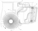
도 1은 본 발명의 바람직한 실시예에 따른 집진 블레이드가 구비된 청소 로봇의 사시도이다.
도 2는 본 발명의 바람직한 실시예에 따른 집진 블레이드가 구비된 청소 로봇의 부분단면도이다.
도 3은 본 발명의 바람직한 실시예에 따른 집진 블레이드와 먼지통의 분해 사시도이다.
도 4는 본 발명의 바람직한 실시예에 따른 집진 블레이드의 측면도이다.
도 5는 집진 블레이드가 변형된 상태를 도시한 도면이다.
도 6은 집진 블레이드가 먼지통에 장착된 상태를 나타낸 사시도이다.
도 7은 먼지통에서 집진 블레이드를 분리하는 상태를 나타낸 사시도이다.
도 8은 회동부가 힌지에 결합되는 상태를 도시한 단면도이다.1 is a perspective view of a cleaning robot having a dust collecting blade according to a preferred embodiment of the present invention.
2 is a partial cross-sectional view of a cleaning robot having a dust collecting blade according to a preferred embodiment of the present invention.
3 is an exploded perspective view of a dust collecting blade and a dust container according to a preferred embodiment of the present invention.
4 is a side view of the dust collecting blade according to the preferred embodiment of the present invention.
5 is a view illustrating a state in which the dust collecting blades are deformed.
6 is a perspective view showing a state in which the dust collecting blade is mounted on the dust container.
7 is a perspective view illustrating a state in which a dust collecting blade is separated from a dust container.
8 is a cross-sectional view showing a state in which the rotating unit is coupled to the hinge.
이하, 본 발명의 바람직한 실시예를 첨부된 도면들을 참조하여 상세하게 설명한다. 우선 각 도면의 구성 요소들에 참조 부호를 첨가함에 있어서, 동일한 구성 요소들에 대해서는 비록 다른 도면상에 표시되더라도 가능한 한 동일한 부호를 가지도록 하고 있음에 유의해야 한다. 또한, 본 발명의 요지를 흐릴 수 있다고 판단되는 경우에는 그 상세한 설명은 생략한다. 또한, 이하에서 본 발명의 바람직한 실시예를 설명할 것이나, 본 발명의 기술적 사상은 이에 한정하거나 제한되지 않고 당업자에 의해 실시될 수 있음은 물론이다.Hereinafter, exemplary embodiments of the present invention will be described in detail with reference to the accompanying drawings. First, in adding reference numerals to the components of each drawing, it should be noted that the same reference numerals are used as much as possible even if displayed on different drawings. In addition, detailed description is abbreviate | omitted when it is judged that it may obscure the summary of this invention. In addition, preferred embodiments of the present invention will be described below, but the technical idea of the present invention may be implemented by those skilled in the art without being limited or limited thereto.
도 1은 본 발명의 바람직한 실시예에 따른 집진 블레이드가 구비된 청소 로봇의 사시도이고, 도 2는 본 발명의 바람직한 실시예에 따른 집진 블레이드가 구비된 청소 로봇의 부분단면도이다.1 is a perspective view of a cleaning robot with a dust collecting blade according to a preferred embodiment of the present invention, Figure 2 is a partial cross-sectional view of the cleaning robot with a dust collecting blade according to a preferred embodiment of the present invention.
본 발명의 바람직한 실시예에 따른 청소 로봇(1)은 쓰레기를 수거하는 먼지통(100)과, 상기 먼지통(100)에 체결되는 집진 블레이드(200)를 포함한다.The
먼지통(100)은 청소 로봇(1)의 후방에 구비된다. 더욱 상세하게 설명하면, 먼지통(100)은 도 2에 도시된 바와 같이 브러쉬(2)의 후단에 구비되어 상기 브러쉬(2)에 의해 내부로 유입된 쓰레기를 수거하는 역할을 한다.The
이러한 먼지통(100)의 상부에는 먼지통(100)을 용이하게 파지할 수 있도록 하는 먼지통 핸들(104)이 구비된다. 먼지통 핸들(104)은 먼지통(100)을 청소 로봇(1)에 장착하였을 경우에 접어놓는 것이 가능하도록 먼지통(100)의 상부에 힌지결합하여 구비하는 것이 바람직하다.The upper part of the
도 3은 본 발명의 바람직한 실시예에 따른 집진 블레이드와 먼지통의 분해 사시도이다.3 is an exploded perspective view of a dust collecting blade and a dust container according to a preferred embodiment of the present invention.
먼지통(100)의 전면 하부에는 쓰레기가 유입되도록 개방형성되는 유입구(106)가 구비된다.The lower portion of the front surface of the
먼지통(100)은 일측에 내부방향을 향해 오목한 요홈의 형태로 형성되는 후크 삽입홈(110)을 구비한다. 또한, 먼지통(100)의 타측에는 수직방향으로 돌출형성되는 힌지(120)가 구비된다.
상기 후크 삽입홈(110)과 힌지(120)는 먼지통(100)에 집진 블레이드(200)를 탈착시키기 위해 구비되는 것으로 후에 집진 블레이드(200)와 함께 상세하게 설명한다.The
먼지통(100)은 유입구(106)의 하부를 막도록 하부면으로부터 미리 정해진 높이만큼 돌출형성되는 흘림 방지판(124)을 구비한다. 상기 흘림 방지판(124)은 집진 블레이드(200)를 먼지통(100)에서 분리시킬 때 유입구(106)에 가까이 모여있는 분진 등의 쓰레기가 임의로 쏟아지게 되는 것을 방지하는 역할을 한다.The
여기서 흘림 방지판(124)의 높이는 집진 블레이드(200)의 높이보다 작게 형성하여 먼지통(100) 내부로 쓰레기가 원활하게 유입될 수 있도록 한다.Here, the height of the
집진 블레이드(200)는 유입구(106)의 전방에 장착된다. 이러한 집진 블레이드(200)는 브러쉬(2)의 회전에 의해 후방으로 이송되는 쓰레기가 먼지통(100) 내부로 유입되도록 가이드하는 역할을 한다.The dust collecting
도 4는 본 발명의 바람직한 실시예에 따른 집진 블레이드의 측면도이고, 도 5는 집진 블레이드가 변형된 상태를 도시한 도면이다.Figure 4 is a side view of the dust collecting blade according to a preferred embodiment of the present invention, Figure 5 is a view showing a state in which the dust collecting blade is deformed.
도 4에 도시된 바와 같이, 집진 블레이드(200)는 후면에 집진 블레이드(200)의 길이방향, 즉 횡방향을 따라 길게 형성되는 지지돌기(202)를 복수 개 구비한다.As illustrated in FIG. 4, the dust collecting
집진 블레이드(200)는 청소 로봇(1)의 청소 도중 그 하단부가 솟아오른 바닥이나 바닥에 있는 장애물에 접하게 되면, 청소 로봇(1)의 주행에 방해되지 않도록 휘어져서 장애물 등을 통과할 수 있어야 한다.When the dust collecting
예를 들어, 청소 로봇(1)이 문턱을 넘거나 카펫 위를 이동하는 경우, 집진 블레이드(200)는 도 5에 도시된 바와 같이 바닥으로부터 솟아오른 문턱 또는 카펫과 같은 장애물에 접하더라도 주행방향의 반대방향으로 휘어지면서 장애물을 지나쳐갈 수 있도록 형성되어야 하는 것이다.For example, when the
그런데, 이와 같이 집진 블레이드(200)가 바닥에 접하여 휘어지게 되면 초기에는 집진 블레이드(200) 자체의 탄성에 의해 그 형태가 복원될 수 있으나, 이러한 휨이 반복될 경우에는 집진 블레이드(200)가 탄성을 잃고 영구적으로 변형된다.By the way, when the dust collecting
이렇게 되면, 브러쉬(2)와 집진 블레이드(200) 단부 사이의 거리가 멀어지게 되어 브러쉬(2)에 의해 후방으로 이송된 쓰레기를 먼지통(100) 내부로 유입시키는 것이 어렵게 되는 문제가 발생하게 된다.In this case, a distance between the
상기 지지돌기(202)는 집진 블레이드(200)의 복원력을 향상시키고, 영구적 변형이 발생되는 것을 방지하여 장시간 동안 높은 청소효율이 지속되도록 하는 역할을 한다.The
바람직하게 복수 개 구비되는 지지돌기(202)는 상기 집진 블레이드(200)의 하단에 가깝게 배치되는 것일수록 직경이 작게 형성되도록 하여 더욱 원활하게 휘어질 수 있도록 한다.Preferably, the plurality of
이러한 지지돌기(202)는 집진 블레이드(200)의 길이방향으로 형성됨에 따라 집진 블레이드(200)가 문턱이나 카펫 등을 용이하게 통과할 수 있도록 충분히 휘어지는 것이 가능하게 되는 것이다.As the
도 6은 집진 블레이드가 먼지통에 장착된 상태를 나타낸 사시도이고, 도 7은 먼지통에서 집진 블레이드를 분리하는 상태를 나타낸 사시도이다.6 is a perspective view showing a state in which the dust collecting blade is mounted on the dust container, Figure 7 is a perspective view showing a state of separating the dust collecting blade from the dust container.
집진 블레이드(200)는 상기 후크 삽입홈(110)에 탈착되는 후크부(210)와 상기 힌지(120)에 결합되어 회동되는 회동부(220)를 구비한다.The
후크부(210)는 상기 후크 삽입홈(110)에 대응되도록 집진 블레이드(200)의 일측에 위치한다. 후크부(210)의 일단에는 후크 삽입홈(110)에 걸리도록 이루어지는 후크(212)가 형성된다.The
상기와 같이 형성되는 후크(212)는 후크 삽입홈(110)에 걸리도록 탄지된 상태에서 소정의 힘을 가함으로써 상기 후크 삽입홈(110)에서 분리시킬 수 있도록 구비된다.The
회동부(220)는 상기 힌지(120)의 위치에 대응되는 집진 블레이드(200)의 타측에 구비된다. 회동부(220)는 힌지(120)에 결합된 상태로 회동되어 유입구(106)를 개폐시키는 역할을 한다.The
도 8은 회동부가 힌지에 결합되는 상태를 도시한 단면도이다.8 is a cross-sectional view showing a state in which the rotating unit is coupled to the hinge.
회동부(220)는 내주면이 상기 힌지(120)의 외주면에 접하도록 형성되는 힌지 삽입구(222)를 구비한다. 힌지 삽입구(222)는 힌지(120)에 결합 및 분리가 가능하도록 반원형이나 'c'자형으로 형성되는 것이 바람직하다.Rotating
상기와 같이 힌지 삽입구(222)를 형성함으로써 도3에 도시된 바와 같이 집진 블레이드(200)를 먼지통(100)으로부터 완전히 분리시키는 것이 가능하게 되고, 이에 따라 집진 블레이드(200)가 손상되거나 수명이 다하게 되었을 경우 용이하게 교체할 수 있게 되는 것이다. 또한, 집진 블레이드(200)를 완전히 분리시킬 경우, 먼지통(100)의 내부를 더욱 용이하게 청소할 수 있게 된다.By forming the
한편, 먼지통(100)은 힌지 삽입구(222)가 힌지(120)에 결합된 상태에서 상기 힌지 삽입구(222)의 외주면을 감싸도록 형성되는 분리 방지부(122)를 구비한다.On the other hand, the
분리 방지부(122)는 힌지(120)에 결합된 힌지 삽입구(222)가 분리 방지부(122)와의 간섭을 피해 소정 각도 이상 회동되어야만 분리될 수 있도록 하는 역할을 한다.The
이러한 구성으로 인해, 후크부(210)가 후크 삽입홈(110)으로부터 분리된 상태에서도 힌지 삽입구(222)는 힌지(120)에 결합된 상태를 유지할 수 있게 되어 집진 블레이드(200)가 먼지통(100)에서 임의로 이탈되는 것을 방지하게 되는 것이다.Due to this configuration, even when the
이상의 설명은 본 발명의 기술 사상을 예시적으로 설명한 것에 불과한 것으로서, 본 발명이 속하는 기술 분야에서 통상의 지식을 가진 자라면 본 발명의 본질적인 특성에서 벗어나지 않는 범위 내에서 다양한 수정, 변경 및 치환이 가능할 것이다. 따라서 본 발명에 개시된 실시예 및 첨부된 도면들은 본 발명의 기술 사상을 한정하기 위한 것이 아니라 설명하기 위한 것이고, 이러한 실시예 및 첨부된 도면에 의하여 본 발명의 기술 사상의 범위가 한정되는 것은 아니다. 본 발명의 보호범위는 아래의 청구 범위에 의해서 해석되어야 하며, 그와 동등한 범위 내에 있는 모든 기술 사상은 본 발명의 권리 범위에 포함되는 것으로 해석되어야 할 것이다.The above description is merely illustrative of the technical idea of the present invention, and various modifications, changes, and substitutions may be made by those skilled in the art without departing from the essential characteristics of the present invention. will be. Accordingly, the embodiments disclosed in the present invention and the accompanying drawings are not intended to limit the technical spirit of the present invention but to describe the present invention, and the scope of the technical idea of the present invention is not limited by the embodiments and the accompanying drawings. The scope of protection of the present invention should be construed according to the following claims, and all technical ideas within the scope of equivalents thereof should be construed as being included in the scope of the present invention.
1 : 청소 로봇2 : 브러쉬
100 : 먼지통104 : 먼지통 핸들
106 : 유입구110 : 후크 삽입부
120 : 힌지122 : 분리 방지부
124 :먼지흘림 방지판200 : 집진 블레이드
202 : 지지돌기210 : 후크부
212 : 후크220 : 회동부
222 : 힌지 삽입구1: cleaning robot 2: brush
100: dust bin 104: dust bucket handle
106: inlet 110: hook insertion portion
120: hinge 122: separation prevention part
124: dust spill prevention plate 200: dust collecting blade
202: support protrusion 210: hook portion
212: hook 220: rotating part
222 hinge opening
Claims (10)
Translated fromKorean상기 먼지통의 일측에 탈착되도록 일단에 후크가 형성된 후크부; 및
상기 먼지통의 타측에 힌지결합되어 회동되는 회동부를 더 포함하는 것을 특징으로 하는 청소 로봇의 집진 블레이드 구조.The method of claim 1,
A hook portion having a hook formed at one end to be detached from one side of the dust container; And
Dust collecting blade structure of the cleaning robot, characterized in that it further comprises a rotating part hinged to the other side of the dust container is rotated.
상기 복수 개의 지지돌기는 상기 집진 블레이드의 하단에 가깝게 배치되는 것일수록 직경이 작게 형성되는 것을 특징으로 하는 집진 블레이드 구조.The method of claim 1,
The plurality of support protrusions are dust collecting blade structure, characterized in that the diameter is formed smaller as the closer to the lower end of the dust collecting blade.
상기 회동부는 상기 먼지통에 형성되는 힌지에 결합 및 분리가 가능하도록 'c'자 형태로 형성되는 힌지 삽입구를 구비하는 것을 특징으로 하는 청소 로봇의 집진 블레이드 구조.The method of claim 2,
The rotating part dust collecting blade structure of the cleaning robot, characterized in that it comprises a hinge insertion opening formed in the 'c' shape to be coupled to and separated from the hinge formed in the dust container.
상기 유입구의 전방에 장착되어 상기 먼지통 내부로 쓰레기가 유입되도록 가이드하고, 후면에 횡방향으로 형성되는 복수 개의 지지돌기를 구비하는 집진 블레이드를 포함하는 것을 특징으로 하는 청소 로봇.Dust bin for collecting the waste introduced through the inlet formed on the front; And
And a dust collecting blade mounted at the front of the inlet to guide the garbage into the dust container and having a plurality of supporting protrusions formed in the transverse direction at the rear side thereof.
상기 먼지통은 일측에 요홈의 형태로 형성되는 후크 삽입홈을 구비하고, 타측에는 수직방향으로 돌출형성되는 힌지를 구비하며,
상기 집진 블레이드는 상기 후크 삽입홈에 탈착되는 후크가 형성된 후크부와, 상기 힌지에 결합되어 회동되는 회동부를 구비하는 것을 특징으로 하는 청소 로봇.The method of claim 5, wherein
The dust container is provided with a hook insertion groove formed in the form of a groove on one side, the other side is provided with a hinge protruding in the vertical direction,
The dust collecting blade is a cleaning robot, characterized in that it comprises a hook portion formed with a hook detachable to the hook insertion groove, and a rotating portion coupled to the hinge is rotated.
상기 복수 개의 지지돌기는
상기 집진 블레이드의 하단에 가깝게 배치되는 것일수록 직경이 작게 형성되는 것을 특징으로 하는 청소 로봇.The method of claim 5, wherein
The plurality of support protrusions
Cleaning robot, characterized in that the smaller the diameter is arranged closer to the lower end of the dust collecting blade.
상기 회동부는
상기 먼지통에 형성되는 힌지에 결합 및 분리가 가능하도록 'c'자 형태로 형성되는 힌지 삽입구를 구비하는 것을 특징으로 하는 청소 로봇.The method according to claim 6,
The rotating part
Cleaning robot, characterized in that provided with a hinge insertion port formed in the 'c' shape to be coupled to and separated from the hinge formed in the dust container.
상기 먼지통은
상기 힌지 삽입구가 상기 힌지에 결합된 상태에서 상기 힌지 삽입구의 외주면을 감싸도록 형성되는 분리 방지부를 구비하고,
상기 힌지 삽입구는 상기 분리 방지부와의 간섭을 피해 미리 정해진 각도만큼 회동시킨 후 분리되도록 하는 것을 특징으로 하는 청소 로봇.The method of claim 8,
The dust bin is
And a separation prevention part formed to surround an outer circumferential surface of the hinge insertion hole in a state where the hinge insertion hole is coupled to the hinge,
The hinge insertion port is a cleaning robot, characterized in that to be separated after rotating by a predetermined angle to avoid interference with the separation prevention unit.
상기 먼지통은
상기 유입구의 하부를 막도록 하부면으로부터 미리 정해진 높이만큼 돌출형성되는 흘림 방지판을 구비하는 것을 특징으로 하는 청소 로봇.The method of claim 5, wherein
The dust bin is
And a spill preventing plate protruding from a lower surface to a predetermined height so as to block a lower portion of the inlet.
Priority Applications (4)
| Application Number | Priority Date | Filing Date | Title |
|---|---|---|---|
| KR1020100028147AKR101083395B1 (en) | 2010-03-29 | 2010-03-29 | Dust Collecting Blade of Cleaning Robot and Cleaning Robot therewith |
| JP2013502466AJP5519073B2 (en) | 2010-03-29 | 2011-03-29 | Dust collection blade structure of cleaning robot and cleaning robot provided with the same |
| EP11762990.7AEP2554086B1 (en) | 2010-03-29 | 2011-03-29 | Dust collection blade structure for cleaning robot and cleaning robot having same |
| PCT/KR2011/002124WO2011122818A2 (en) | 2010-03-29 | 2011-03-29 | Dust collection blade structure for cleaning robot and cleaning robot having same |
Applications Claiming Priority (1)
| Application Number | Priority Date | Filing Date | Title |
|---|---|---|---|
| KR1020100028147AKR101083395B1 (en) | 2010-03-29 | 2010-03-29 | Dust Collecting Blade of Cleaning Robot and Cleaning Robot therewith |
Publications (2)
| Publication Number | Publication Date |
|---|---|
| KR20110108761A KR20110108761A (en) | 2011-10-06 |
| KR101083395B1true KR101083395B1 (en) | 2011-11-14 |
Family
ID=44712735
Family Applications (1)
| Application Number | Title | Priority Date | Filing Date |
|---|---|---|---|
| KR1020100028147AActiveKR101083395B1 (en) | 2010-03-29 | 2010-03-29 | Dust Collecting Blade of Cleaning Robot and Cleaning Robot therewith |
Country Status (4)
| Country | Link |
|---|---|
| EP (1) | EP2554086B1 (en) |
| JP (1) | JP5519073B2 (en) |
| KR (1) | KR101083395B1 (en) |
| WO (1) | WO2011122818A2 (en) |
Cited By (2)
| Publication number | Priority date | Publication date | Assignee | Title |
|---|---|---|---|---|
| KR101378306B1 (en)* | 2012-03-21 | 2014-03-27 | 주식회사 유진로봇 | Dust Collecting Blade of Cleaning Robot and Cleaning Robot therewith |
| KR101573192B1 (en) | 2014-05-30 | 2015-12-01 | 주식회사 유진로봇 | Cleaning robot having improved driving and cleaning ability |
Families Citing this family (6)
| Publication number | Priority date | Publication date | Assignee | Title |
|---|---|---|---|---|
| EP2999387B1 (en)* | 2013-05-23 | 2020-06-24 | Alfred Kärcher SE & Co. KG | Floor cleaning device, in particular self-propelled and self-steering floor cleaning appliance |
| TW201446202A (en)* | 2013-06-05 | 2014-12-16 | Uni Ring Tech Co Ltd | Sweeping bottom cover structure of self-propelled cleaning device and assembly and scraping method thereof |
| CN104224054B (en)* | 2013-06-13 | 2018-03-30 | 科沃斯机器人股份有限公司 | Sweeping robot |
| JP6204080B2 (en)* | 2013-06-17 | 2017-09-27 | 東芝ライフスタイル株式会社 | Electric vacuum cleaner |
| JP2018007909A (en)* | 2016-07-14 | 2018-01-18 | 日立アプライアンス株式会社 | Self-propelled vacuum cleaner |
| KR102136536B1 (en)* | 2018-08-02 | 2020-07-22 | 주식회사 유진로봇 | Apparatus for Improving Driving Performance for Rotating Type Rag Kit for Wet Robot Cleaner |
Citations (2)
| Publication number | Priority date | Publication date | Assignee | Title |
|---|---|---|---|---|
| KR100588061B1 (en) | 2004-12-22 | 2006-06-09 | 주식회사유진로보틱스 | Cleaning Robot with Double Suction |
| KR100761667B1 (en) | 2006-03-06 | 2007-10-01 | 주식회사 대우일렉트로닉스 | Zero exhaust robot cleaner |
Family Cites Families (12)
| Publication number | Priority date | Publication date | Assignee | Title |
|---|---|---|---|---|
| JP2583958B2 (en)* | 1988-04-20 | 1997-02-19 | 松下電器産業株式会社 | Floor nozzle for vacuum cleaner |
| US5212848A (en)* | 1992-03-13 | 1993-05-25 | Tennant Company | Squeegee blade |
| US5881417A (en)* | 1994-04-25 | 1999-03-16 | Windsor Industries, Inc. | Floor cleaning apparatus with contouring broom |
| JP3188116B2 (en)* | 1994-09-26 | 2001-07-16 | 日本輸送機株式会社 | Self-propelled vacuum cleaner |
| JP3299847B2 (en)* | 1994-10-17 | 2002-07-08 | 日本輸送機株式会社 | Self-propelled vacuum cleaner |
| US7571511B2 (en)* | 2002-01-03 | 2009-08-11 | Irobot Corporation | Autonomous floor-cleaning robot |
| JP3903299B2 (en)* | 2001-06-21 | 2007-04-11 | 三菱電機株式会社 | Floor brush for vacuum cleaner |
| JP4133853B2 (en)* | 2004-01-30 | 2008-08-13 | シャープ株式会社 | Self-propelled vacuum cleaner |
| US7620476B2 (en)* | 2005-02-18 | 2009-11-17 | Irobot Corporation | Autonomous surface cleaning robot for dry cleaning |
| US7389166B2 (en)* | 2005-06-28 | 2008-06-17 | S.C. Johnson & Son, Inc. | Methods to prevent wheel slip in an autonomous floor cleaner |
| KR20070021763A (en)* | 2005-08-19 | 2007-02-23 | 주식회사 대우일렉트로닉스 | Zero exhaust robot cleaner |
| KR100848964B1 (en)* | 2006-12-22 | 2008-07-29 | 주식회사 유진로봇 | Suction Assembly of Robot Cleaner |
- 2010
- 2010-03-29KRKR1020100028147Apatent/KR101083395B1/enactiveActive
- 2011
- 2011-03-29WOPCT/KR2011/002124patent/WO2011122818A2/enactiveApplication Filing
- 2011-03-29EPEP11762990.7Apatent/EP2554086B1/ennot_activeNot-in-force
- 2011-03-29JPJP2013502466Apatent/JP5519073B2/enactiveActive
Patent Citations (2)
| Publication number | Priority date | Publication date | Assignee | Title |
|---|---|---|---|---|
| KR100588061B1 (en) | 2004-12-22 | 2006-06-09 | 주식회사유진로보틱스 | Cleaning Robot with Double Suction |
| KR100761667B1 (en) | 2006-03-06 | 2007-10-01 | 주식회사 대우일렉트로닉스 | Zero exhaust robot cleaner |
Cited By (4)
| Publication number | Priority date | Publication date | Assignee | Title |
|---|---|---|---|---|
| KR101378306B1 (en)* | 2012-03-21 | 2014-03-27 | 주식회사 유진로봇 | Dust Collecting Blade of Cleaning Robot and Cleaning Robot therewith |
| KR101573192B1 (en) | 2014-05-30 | 2015-12-01 | 주식회사 유진로봇 | Cleaning robot having improved driving and cleaning ability |
| WO2015183037A1 (en)* | 2014-05-30 | 2015-12-03 | (주)유진로봇 | Cleaning robot having improved running and cleaning capacities |
| US9872594B2 (en) | 2014-05-30 | 2018-01-23 | Yujin Robot Co., Ltd. | Cleaning robot having improved driving and cleaning ability |
Also Published As
| Publication number | Publication date |
|---|---|
| EP2554086A2 (en) | 2013-02-06 |
| KR20110108761A (en) | 2011-10-06 |
| EP2554086B1 (en) | 2015-11-18 |
| JP2013523250A (en) | 2013-06-17 |
| JP5519073B2 (en) | 2014-06-11 |
| WO2011122818A2 (en) | 2011-10-06 |
| WO2011122818A3 (en) | 2012-01-26 |
| EP2554086A4 (en) | 2013-10-16 |
Similar Documents
| Publication | Publication Date | Title |
|---|---|---|
| KR101083395B1 (en) | Dust Collecting Blade of Cleaning Robot and Cleaning Robot therewith | |
| KR102266928B1 (en) | Mop module and robot cleaner having the same | |
| US20180360281A1 (en) | Suction structure of robot vacuum cleaner | |
| EP2433541B1 (en) | Robot cleaner | |
| EP2181634B1 (en) | Vacuum cleaner nozzle unit | |
| US8721779B2 (en) | Ceiling embedded type air conditioner | |
| EP3178361B1 (en) | Robot cleaner | |
| AU2013201339B2 (en) | Robot cleaner | |
| EP3205250A1 (en) | Autonomous travel-type cleaner | |
| EP3000372B1 (en) | Robot cleaner | |
| KR101667716B1 (en) | Robot cleaner | |
| KR20140136814A (en) | Industrial vacuum cleaner having dust removal device | |
| CN113261886A (en) | Cleaning system | |
| KR101352287B1 (en) | Nozzle cover and robot cleaner comprising the same | |
| JP5374414B2 (en) | Toilet bowl | |
| KR20150075642A (en) | Suction port of vacuum cleaner robot | |
| JP2007307335A (en) | Dust remover for electrostatic cleaner | |
| CN114305263B (en) | Cleaning base station and cleaning machine system | |
| JP5974292B2 (en) | Range food | |
| CN209712771U (en) | Mopping machine dust box and mopping machine comprising same | |
| JP2018054205A (en) | Range food | |
| CN115886658A (en) | A base station for automatic cleaning of cleaning robots | |
| CN219878056U (en) | A water tank and cleaning device | |
| CN217907591U (en) | Dust collector and dust cup thereof | |
| KR20060101082A (en) | Dust collection unit of vacuum cleaner combined with water cleaning |
Legal Events
| Date | Code | Title | Description |
|---|---|---|---|
| A201 | Request for examination | ||
| PA0109 | Patent application | Patent event code:PA01091R01D Comment text:Patent Application Patent event date:20100329 | |
| PA0201 | Request for examination | ||
| E701 | Decision to grant or registration of patent right | ||
| PE0701 | Decision of registration | Patent event code:PE07011S01D Comment text:Decision to Grant Registration Patent event date:20110914 | |
| PG1501 | Laying open of application | ||
| GRNT | Written decision to grant | ||
| PR0701 | Registration of establishment | Comment text:Registration of Establishment Patent event date:20111108 Patent event code:PR07011E01D | |
| PR1002 | Payment of registration fee | Payment date:20111109 End annual number:3 Start annual number:1 | |
| PG1601 | Publication of registration | ||
| FPAY | Annual fee payment | Payment date:20141105 Year of fee payment:4 | |
| PR1001 | Payment of annual fee | Payment date:20141105 Start annual number:4 End annual number:4 | |
| FPAY | Annual fee payment | Payment date:20151102 Year of fee payment:5 | |
| PR1001 | Payment of annual fee | Payment date:20151102 Start annual number:5 End annual number:5 | |
| FPAY | Annual fee payment | Payment date:20161101 Year of fee payment:6 | |
| PR1001 | Payment of annual fee | Payment date:20161101 Start annual number:6 End annual number:6 | |
| FPAY | Annual fee payment | Payment date:20171101 Year of fee payment:7 | |
| PR1001 | Payment of annual fee | Payment date:20171101 Start annual number:7 End annual number:7 | |
| FPAY | Annual fee payment | Payment date:20191106 Year of fee payment:9 | |
| PR1001 | Payment of annual fee | Payment date:20191106 Start annual number:9 End annual number:9 | |
| PR1001 | Payment of annual fee | Payment date:20201102 Start annual number:10 End annual number:10 | |
| PR1001 | Payment of annual fee | Payment date:20211102 Start annual number:11 End annual number:11 | |
| PR1001 | Payment of annual fee | Payment date:20220913 Start annual number:12 End annual number:12 |