KR101083142B1 - Broadband antenna - Google Patents
Broadband antennaDownload PDFInfo
- Publication number
- KR101083142B1 KR101083142B1KR1020067009654AKR20067009654AKR101083142B1KR 101083142 B1KR101083142 B1KR 101083142B1KR 1020067009654 AKR1020067009654 AKR 1020067009654AKR 20067009654 AKR20067009654 AKR 20067009654AKR 101083142 B1KR101083142 B1KR 101083142B1
- Authority
- KR
- South Korea
- Prior art keywords
- radiator
- coupling element
- base plate
- broadband antenna
- coupling
- Prior art date
- Legal status (The legal status is an assumption and is not a legal conclusion. Google has not performed a legal analysis and makes no representation as to the accuracy of the status listed.)
- Expired - Fee Related
Links
Images


Classifications
- H—ELECTRICITY
- H01—ELECTRIC ELEMENTS
- H01Q—ANTENNAS, i.e. RADIO AERIALS
- H01Q21/00—Antenna arrays or systems
- H01Q21/29—Combinations of different interacting antenna units for giving a desired directional characteristic
- H—ELECTRICITY
- H01—ELECTRIC ELEMENTS
- H01Q—ANTENNAS, i.e. RADIO AERIALS
- H01Q21/00—Antenna arrays or systems
- H01Q21/06—Arrays of individually energised antenna units similarly polarised and spaced apart
- H01Q21/20—Arrays of individually energised antenna units similarly polarised and spaced apart the units being spaced along or adjacent to a curvilinear path
- H01Q21/205—Arrays of individually energised antenna units similarly polarised and spaced apart the units being spaced along or adjacent to a curvilinear path providing an omnidirectional coverage
- H—ELECTRICITY
- H01—ELECTRIC ELEMENTS
- H01Q—ANTENNAS, i.e. RADIO AERIALS
- H01Q5/00—Arrangements for simultaneous operation of antennas on two or more different wavebands, e.g. dual-band or multi-band arrangements
- H01Q5/50—Feeding or matching arrangements for broad-band or multi-band operation
- H—ELECTRICITY
- H01—ELECTRIC ELEMENTS
- H01Q—ANTENNAS, i.e. RADIO AERIALS
- H01Q9/00—Electrically-short antennas having dimensions not more than twice the operating wavelength and consisting of conductive active radiating elements
- H01Q9/04—Resonant antennas
- H01Q9/30—Resonant antennas with feed to end of elongated active element, e.g. unipole
- H01Q9/40—Element having extended radiating surface
Landscapes
- Details Of Aerials (AREA)
- Waveguide Aerials (AREA)
Abstract
Description
Translated fromKorean본 발명은 청구범위 제 1 항의 전 방향성 안테나인 광대역 안테나에 관한 것이다.The present invention relates to a wideband antenna which is the omni-directional antenna of
전 방향성 안테나는 바람직하게는 수직 편파에서 방사하고 다중 대역 가능한, 예를 들어 실내(indoor) 안테나로서 공지되어 있다. 이 안테나는 기부판을 포함하는데, 이 기부판 상에서 횡방향으로, 즉, 기부판에 대해 수평으로 단극 형태의 방사기가 돌출되어 있다. 전체 시스템은 통상 보호 하우징(레이돔=radome)으로 덮여 있다.Omni-directional antennas are preferably known as, for example, indoor antennas which radiate in vertical polarization and are multiband capable. The antenna includes a base plate, on which a single-pole radiator protrudes transversely, ie horizontally relative to the base plate. The whole system is usually covered with a protective housing (radome = radome).
금속 또는 적어도 전도성이고 평면도에서 통상 원형으로 구성된 기부판 상에는 그 중앙에 또는 중앙 근처에서 중앙에 대해 약간 오프셋(offset) 된 리세스(recess)가 마련되는데 이 리세스 내에는 플러그 결합(plug connection)을 위한 플러그 요소가 고정되는데 이는 통상 플러그 형태의 접촉 요소이다. 하부측으로부터 접촉 요소까지 동축 케이블이 제2 플러그 요소로서, 통상 부시(bush) 형태의 플러그(plug) 요소로서 접속된다. 급전 케이블의 외부 도체는 기부판 상으로 돌출된 단극 형태의 방사기와 전기적으로 연결된다. 다시 말해, 내부 도체는 전기적 전도성(electrically conductively)에서 기부판(base plate)으로부터 분리되므로, 연결된 동축 케이블의 외부 도체로부터 분리된다.On a base plate consisting of metal or at least conductive and usually circular in plan view, a recess is provided at or slightly offset from the center at or near the center of which a plug connection is provided. The plug element is fixed, which is usually a contact element in the form of a plug. The coaxial cable from the bottom side to the contact element is connected as a second plug element, usually as a plug element in the form of a bush. The outer conductor of the feed cable is electrically connected to the single-pole radiator protruding onto the base plate. In other words, the inner conductor is separated from the base plate at the electrically conductively and thus from the outer conductor of the connected coaxial cable.
이러한 형태의 전 방향성 안테나는 동시에 복수의 주파수 범위, 즉, 동시에 복수의 주파수 대역에서 방사할 수 있도록 구성된다.This type of omni-directional antenna is configured to be capable of radiating simultaneously in a plurality of frequency ranges, that is, in a plurality of frequency bands at the same time.
이와 같이 본 출원인은 상기 유형의 실내 전 방향성 안테나인 광대역 안테나를 제조하여 제공하였으며, 이러한 안테나는 예를 들어 이하와 같은 주파수 범위에서 방사할 수 있다.As described above, the present inventor has manufactured and provided a broadband antenna which is the indoor omnidirectional antenna of the above type, and the antenna can emit, for example, in the following frequency range.
824 - 960 MHz824-960 MHz
1425 - 1710 MHz1425-1710 MHz
1710 - 1880 MHz1710-1880 MHz
1850 - 1990 MHz1850-1990 MHz
1920 - 2170 MHz1920-2170 MHz
또한 본 출원인이 제조하여 판매중인 다중 대역성 안테나도 공지되어 있고 이하와 같은 주파수로 동시에 작동 가능하다.Multiband antennas are also known and commercially available from the Applicant and are capable of operating simultaneously at the following frequencies.
876 - 890 MHz876-890 MHz
890 - 960 MHz890-960 MHz
1710 - 2170 MHz1710-2170 MHz
2170 - 2500 MHz2170-2500 MHz
일반 유형의 안테나는 예를 들어 DE 37 09 163 C2 및 US 4 972 196에 공지되어 있다.Antennas of the general type are known, for example, from DE 37 09 163 C2 and US 4 972 196.
상기 전자의 공보에서 언급된 안테나는 컨덴서(capacitor)의 중간 연결 하에 내부 도체를 통해 급전되는 로드형(rod-shaped) 안테나를 나타낸다.The antenna mentioned in the former publication represents a rod-shaped antenna which is fed through an inner conductor under an intermediate connection of a capacitor.
후자의 공보에는 중앙에서 용량성으로 급전되는 디스크 형태(disk-shaped)의 방사 요소(antenna element)를 갖는 평면 안테나(planar antenna)가 공지되어 있다.The latter publication discloses a planar antenna with a disk-shaped antenna element which is capacitively fed at the center.
본 발명의 목적은 전 방향성 안테나로서 사용될 수 있고 단순하게 구성되고 비교적 매우 작게 구성되는 다중 대역성, 즉, 전체적으로 매우 광대역적인 안테나를 제공하는 것이다. 이때 안테나는 더 큰 대역폭으로 동시에 작동될 수 있다.It is an object of the present invention to provide a multiband, i.e. very broadband, antenna as a whole which can be used as an omnidirectional antenna and which is simply constructed and relatively very small. The antennas can then be operated simultaneously with greater bandwidth.
본 발명에 따르면, 이러한 목적은 청구범위 제1항의 특징에 의해 달성된다. 본 발명의 바람직한 구성은 종속 청구항에 기재된다.According to the invention, this object is achieved by the features of
상이한 주파수 범위에서 동시적인 작동을 위해 상당히 확장된 대역폭이 단지 매우 작게 구성된 안테나에 의해서, 안테나의 급전이 방사기의 풋(foot) 지점에 대한 직렬 또는 용량성 라인 결합부(line coupling)를 이용하여 실행될 수 있다는 것은 매우 주목할 만하다.With an antenna configured with only very small bandwidths for simultaneous operation in different frequency ranges, the feeding of the antenna can be carried out using series or capacitive line coupling to the foot of the emitter. It is very noteworthy that it can.
이를 통해 매우 큰 대역폭이 가능하다. 본 발명에 따른 안테나는 예를 들어 문제없이, 동시에 800 내지 1000 MHz 대역에서, 1400 내지 3500 MHz 대역에서 그리고 예를 들어 5000 내지 6000 MHz 대역에서도 작동될 수 있다. 직렬(용량성) 라인 결합으로 인해 상부 대역에는 공명이 존재할 수 있다.This allows for very large bandwidths. The antenna according to the invention can be operated in the 800-1000 MHz band simultaneously, in the 1400- 3500 MHz band and also in the 5000-6000 MHz band, for example, without problems. Resonance may be present in the upper band due to series (capacitive) line coupling.
본 발명에 따른 안테나는 일반 유형 특성적인 직렬 내지 용량성 결합부를 갖는다. 본 발명에 따르면, 이는 내부 도체 결합에 대해 제 1 결합 요소가 제공되기 때문인데, 이 결합 요소는 평형면을 형성하는 기부판으로부터 전기적 전도성에서 분리되어 연장된다. 이로써, 방사기와 전기적 전도성에서 연결되거나 또는 방사기의 일부인 제 2 라인 결합 요소가 함께 작용한다. 제 1 및 제 2 라인 결합 요소는 전기적 전도성에서 서로 분리되는데, 즉, 전기적 전도적으로 서로 결합되지 않으므로, 직렬 또는 용량성 라인 결합이 형성된다. 상호 작용하는 양 결합 요소는 한편으로는 로드 형태로 다른 한편으로는 튜브 형태로 구성되어, 양 결합 요소가 서로 삽입될 수 있다.The antenna according to the invention has a general type characteristic series to capacitive coupling. According to the invention, this is because a first coupling element is provided for the inner conductor coupling, which coupling element extends in electrical conductivity away from the base plate forming the equilibrium surface. As such, the second line coupling element, which is connected in electrical conductivity or is part of the radiator, acts together. The first and second line coupling elements are separated from each other in electrical conductivity, ie they are not electrically conductively coupled to each other, so that a series or capacitive line coupling is formed. Both interacting elements are configured in the form of rods on the one hand and in the form of tubes on the other, so that both coupling elements can be inserted into one another.
이는, 긴 구성을 통해 최적의 용량성 또는 직렬 결합이 형성될 수 있는 중요한 장점을 제공한다. 또한, 다른 한편으로 이러한 구성에 의해, 특히 상호 작용하는 상기 양 결합 요소들 사이에 절연성 유전체(dielectric)가 제공되고 이를 통해 양 결합 요소의 전도적 분리 시에 이들이 기계적으로 서로 고정 보유될 경우에, 방사기에 대한 상응하는 고정 및 지지 기능에 작용할 수 있다.This provides an important advantage that an optimal capacitive or series coupling can be formed through a long configuration. In addition, on the other hand, by this arrangement, in particular, when an insulating dielectric is provided between the interacting two coupling elements, whereby they are held mechanically fixed to one another during the conductive separation of both coupling elements, It can act on the corresponding fixing and supporting function for the radiator.
본 발명에 따른 단극과 같은 안테나는 회전 대칭이거나 또는 적어도 소정의 각도 영역에서 회전 대칭으로 구성되며, 단극식(form of a monopole)의 안테나의 원추형 또는 원뿔형으로 확장되는 적어도 하나의 부분을 포함한다. 안테나는 전체적으로 외부 형태에서 보았을 때 원추형 또는 원뿔형으로 구성될 수 있다.The antenna, such as the monopole according to the invention, is rotationally symmetrical or is configured at least rotationally symmetrically in a predetermined angular region and comprises at least one part which extends conically or conically of a form of a monopole antenna. The antenna as a whole may be of conical or conical shape when viewed from the outside.
따라서, 안테나는 기본적으로 반경 방향 대칭일 수 있거나 또는 방사 대칭일 수 있는데, 다시 말해 횡단면 행태를 가지므로, 안테나는 중앙축을 중심으로 소정 각도만큼 평면 회전 시에 일치될 수 있다. 이는 예를 들어 방사기에 대해 단독으로 또는 예를 들어 기부판에 대해 단독으로 또는 양자에 대해 적용될 수 있다.Thus, the antenna can be basically radially symmetrical or radially symmetrical, ie having a cross-sectional behavior, so that the antenna can be matched in planar rotation by a certain angle about the central axis. This can be applied for example alone for the radiator or for example alone or for both base plates.
대안적으로, 단극식 또는 단극(monopole)과 유사한 방사기가 원통형으로 구성될 수 있다.Alternatively, a emitter similar to a monopole or a monopole can be constructed in a cylindrical shape.
그러나, 안테나의 단극식의 방사기가, 기부판으로부터 원추형으로 확장된 제 1 요소(first section) 및 이에 연결된 원통형 제 2 요소(second section)로 형성된 형태를 포함할 수 있다. 다시 말해, 방사기는 본 발명에 따라 원추형 또는 원뿔형 그리고 원통형 방사기 부분의 조합으로 구성된다. 방사기의 원추형 부분은 특히 상부 주파수 대역용 단극으로써 작용한다. 이에 반해, 방사기의 원통형 부분은 그에 속한 평형면으로 형성하는 기부판을 이용하여 낮은 주파수에 대해 작용한다. 이를 통해 상부 주파수 대역에 대한 원통형 부분의 반작용이 발생하지 않는 것을 알 수 있다.However, the unipolar radiator of the antenna may comprise a form formed by a first section concentrically extending from the base plate and a cylindrical second section connected thereto. In other words, the radiator consists of a combination of conical or conical and cylindrical radiator parts according to the invention. The conical part of the emitter acts in particular as a monopole for the upper frequency band. In contrast, the cylindrical part of the radiator acts on a low frequency using a base plate formed by its equilibrium plane. It can be seen that the reaction of the cylindrical portion to the upper frequency band does not occur.
직렬 또는 용량성 내부 도체 결합으로 구성된 직렬 또는 용량성 라인 결합은 급전 라인(동축 도체의 내부 도체)과 연결된 로드형 제 1 결합 요소를 통해 실행되며, 이 결합 부분은 기부판으로부터 절연되어 기부판 상으로 돌출한다. 이와 같이 결합된 제 2 결합 요소는 방사기와 연결되거나 또는 방사기의 일부로 형성된다. 제 2 결합 요소가 튜브 형태로 구성되는 것은 바람직하다. 회전 방지를 달성하기 위해 결합 부분은 다각형으로 또는 이와 유사하게, 즉, 예를 들어 n 다각형 단면으로 구성될 수 있다. 일반적으로, 단면 형태는 원형에서 벗어난 형태를 갖도록 구성될 수 있다. 이를 통해, 원추면과 이에 연결된 원통형 부분으로 구성되고 내측에 놓인 (방사기의 기부점으로부터 돌출된) 튜브 부분을 갖는 단극식 방사기가 급전 케이블과 연결된 로드형 제 1 결합 요소 상에 직접 장착될 수 있다. 직렬 라인 결합을 구현하기 위해 제 1 및 제 2 결합 요소, 즉, 급전 라인과 단극식 방사기가 전기적 전도성에서 분리되기 때문에, 제 1 결합 요소의 분리 슬리브(sleeve)가 장착될 수 있는데, 이 분리 슬리브 상에는 단극식의 방사기의 제 2 결합 요소에 장착될 수 있다.Series or capacitive line coupling, consisting of series or capacitive inner conductor coupling, is carried out via a rod-shaped first coupling element connected to a feed line (inner conductor of a coaxial conductor), the coupling portion being insulated from the base plate and on the base plate. To protrude. The second coupling element thus joined is connected to or formed as part of the radiator. It is preferred that the second coupling element is configured in the form of a tube. In order to achieve anti-rotation the joining portion may be configured in polygons or similarly, ie n polygonal cross sections. In general, the cross-sectional shape can be configured to have a shape that is out of circle. This allows a unipolar radiator having a conical surface and a cylindrical part connected thereto and having an inner tube part (projecting from the base point of the radiator) to be mounted directly on the rod-shaped first coupling element connected with the feed cable. Since the first and second coupling elements, i.e., the feed line and the unipolar radiator, are separated in electrical conductivity to realize series line coupling, a separation sleeve of the first coupling element can be mounted, which is a separate sleeve. It can be mounted on the second coupling element of the unipolar radiator.
이로써 최고로 간단한 조립이 달성될 수 있는데, 이는 방사기가 땜납없이, 기부판 상에서 절연된 절연체의 중간 연결 하에 급전 라인과 연결된 제 1 결합 요소 상으로 단지 삽입됨으로 조립될 수 있기 때문이다.This allows the simplest assembly to be achieved, since the radiator can be assembled without soldering only on the first coupling element connected with the feed line under the intermediate connection of the insulator insulated on the base plate.
그러나, 절연체가 예를 들어 사전 선택 가능한 절연 상수를 갖는 플라스틱 재료로 구성되어야만 하는 것은 아니다. 절연체로서 공기가 사용될 수도 있다. 이때, 장착된 방사기가 기부판(base plate)으로부터 돌출된 로드형 결합 요소와 또는 베이스판 또는 기부판 자체와 전기적 전도적으로 접촉될 수 없는 것을 보장하는 적절한 중심 설정 장치 또는 간격 유지기가 사용되어야 한다.However, the insulator does not have to consist of, for example, a plastic material having a preselectable insulation constant. Air may be used as the insulator. Appropriate centering devices or spacers should be used to ensure that the mounted radiator cannot be in electrically conductive contact with the rod-like coupling element protruding from the base plate or with the base plate or the base plate itself. .
또한 직렬 급전으로 인해, 종래 해결책에 비해 방사 고도가 최소화될 수 있다. 또한, 이를 통해 평형면(기부판)의 감소가 가능하므로, 비교적 적은 구성이 구현될 수 있다.In addition, due to the series feeding, the emission altitude can be minimized as compared to the conventional solution. In addition, since it is possible to reduce the balance surface (substrate) through this, a relatively small configuration can be implemented.
이하 본 발명이 실시예를 참조로 상세히 설명된다. 상세하게는,The invention is described in detail below with reference to examples. Specifically,
도 1a는 본 발명에 따른 안테나의 개략 평면도이다.1a is a schematic plan view of an antenna according to the invention.
도 1b는 본 발명에 따른 안테나의 하부도이다.1b is a bottom view of an antenna according to the invention.
도 2는 본 발명에 따른 안테나의 축방향 중앙의 개략적인 수직 횡단면도이다.2 is a schematic vertical cross-sectional view of the axial center of the antenna according to the invention.
도 3은 기부판(1)으로부터 돌출되고 급전 라인과 전기 연결된 로드형 결합 부분의 개략 사시도이다.3 is a schematic perspective view of a rod-shaped engaging portion projecting from the
도 4는 방사기의 제 1 실시예의 개략 사시도이다.4 is a schematic perspective view of a first embodiment of a radiator.
도 5는 변형된 다른 방사기 형태의 축방향 횡단면도이다.5 is an axial cross-sectional view of another modified emitter form.
도 6은 변형된 원추형 내지 절두형 방사기 형태의 축방향 횡단면도이다.6 is an axial cross-sectional view in the form of a modified conical to truncated radiator.
도 7은 장착된 제 1 내측 커버를 갖는 본 발명에 따른 안테나의 축방향 단면도이다.7 is an axial sectional view of an antenna according to the invention with a first inner cover mounted;
도 8은 내부 커버를 완전히 덮은 외부 커버가 장착된, 도 7에 상응하는 횡방향 단면도이다.FIG. 8 is a transverse cross-sectional view corresponding to FIG. 7 with the outer cover fully covered with the inner cover. FIG.
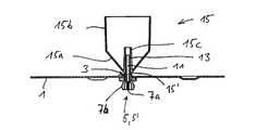
방사기(antenna element)(15)를 갖는 본 발명에 따른 안테나의 제 1 실시예가 도 1a에서 개략 평면도로, 도 1b는 본 발명에 따른 안테나의 하부도이며, 도 2에서 중앙축을 통한 수직 횡단면도로 도시된다.A first embodiment of an antenna according to the invention with an
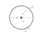
안테나는 도시된 실시예에서 원형 또는 디스크 형태로 구성되는 기부판(base plate)(1) 또는 접지판(ground plate)을 포함한다. 그러나, 기부판(1) 또는 접지판은 완전히 다른 형태를 가질 수도 있다. 예를 들어 정방형, 장방형, 타원형 등으로 형성될 수 있고, 통상 n 각형 또는 임의의 다른 기본 형태 및 경계선을 가질 수 있다. 판(1)은 이하 실제로 기부판(1)으로 표시된다. 기부판(1)은 특히 평형면(counter weight surface)으로서 기능한다.The antenna comprises a
기부판(1)의 중앙에는 리세스(recess)(3)가 구비된다. 리세스(3)의 하부에는 플러그 요소(5)가 위치되어 고정되는데, 이는 도시된 실시예에서 동축(coaxial) 플러그 요소(5')로서 형성된다. 플러그 요소(5)의 외부 도체(7b)는 기부판(1)과 전기적 전도성으로 연결된다. 플러그 요소(5)의 내부 도체(7a)는 외부 도체(7b)로부터 분리되어 리세스(3)를 관통하며, 기부판(1)의 상부에서 연장되는 급전측 또는 제1 결합 요소(11)와 전기적 전도성으로 연결된다. 상기 제 1 결합 요소(11)는 기부판에 대해 횡으로, 즉, 도시된 실시예에서 수평으로 형성된다. 이는 로드 형태로 구성되고 바람직하게는 원형 단면을 갖는다.A
제 1 결합 요소(11) 상에는 튜브 형태의 절연 요소(13)가 장착된다. 절연 요소(13)는 도시된 실시예에서 제 1 결합 요소(11)의 축 방향 길이에 대략 일치하는 길이를 갖는다. 하부 단부에서 절연 요소(13)에는 측면으로 돌출한 플랜지(13a)가 구비되는데, 이는 도시된 실시예에서 마찬가지로 원형 또는 디스크 형태로 구성되고 리세스(3) 영역 내에서 기부판(1) 상에 위치한다.On the
상기 절연 요소(13)는 도 1a 및 도 1b와 도 2에 도시된 방사기(15)에 삽입된다.The insulating
단극식의 방사기(antenna element)(15)는 제 1 방사기 부분(first antennal section)(15a)과 제 2 방사기 부분(second antenna section)(15b)을 갖는다. 제 1 방사기 부분(15a)은 풋 지점(19)으로부터 돌출되어 원추형 또는 원뿔형으로 확장되어 배열되는데, 다시 말해 확장되는 원추형 부분은 기부판(1)으로부터 멀어진다. 이러한 원추형 또는 원뿔형 제 1 방사기 부분(15b)에 원통형 제 2 방사기 부분(15b)이 연결되며, 제1 부분으로부터 제 2 부분으로의 전환부에서 원추형 방사기 부분의 직경은 원통형 방사기 부분의 직경에 상응한다. 이로써 방사기는 기부판에 대해 횡으로 연장하는 종축을 중심으로 연장하는 외부면(outer surface)을 갖게 된다. 방사기(15)는 회전 대칭이거나 또는 부분 회전 대칭 또는 적어도 실제로 주연 대칭 또는 방사 대칭으로 구성된다.The
도 2에 따른 단면도에 도시된 바와 같이, 방사기의 일부는 내측에 구성된 튜브 형태의 결합 요소(15c)이며, 이 결합 요소는 튜브 형태의 절연 요소(13)의 외경보다 약간 크거나 또는 동일한 자유 내경을 포함한다. 이로써 결합 부분과 함께 단극식의 방사기는 절연 요소(13) 상으로, 방사기(15)의 최저 정지면(15')까지 삽입되며, 즉, 풋 지점(19)이 절연 요소(13)의 절연 플랜지(13a) 상에 놓이므로 기부판(1)으로부터 전기적 전도성으로 분리된다.As shown in the cross section according to FIG. 2, a part of the radiator is a tube-shaped
결합 요소(15c)의 축(axial) 방향 길이는 통상 절연 요소의 축 방향 길이 또는 급전 케이블측(feed cable side) 제 1 결합 요소(11)의 축 방향 길이보다 길다. 중공원통형 절연 요소(13)의 길이는 비교적 문제가 없어 확실히 더 짧게 구성될 수 있다. 절연 요소는 실제로 단지 방사기(15)를 기계적으로 보유한 데만 사용되고, 더욱이 방사기(15)의 어떤 부분도, 튜브형 제 2 결합 요소(15c)가 내부 도체와 전기적으로 접속되는 제 1 결합 요소(11)를 접촉할 수 없도록 하는데 기여한다.The axial length of the
도시된 실시예에서 동축으로 서로 배열되고 전기적 전도성에서 분리된 평행한 두 개의 제 1 및 제 2 결합 요소(11, 15c)는 방사기(15)의 풋 지점에 직렬(용량성)의 라인 결합을 형성하는데, 다시 말해 직렬 내지 용량성 내부 도체 결합부를 형성한다. 이로써, 제 1 및 제 2 결합 요소(11, 15c)의 길이는 상이한 주파수 범위에 대해 소정의 최적의 결합이 구현될 수 있도록 선택된다.
방사기 장치의 한 부분을 형성한 제 2 결합요소(15c)는 일반적으로 급전 케이블측에 있는 제 1 결합 요소(11)의 길이보다 길게 선택한다. 급전측 결합 요소(11)의 길이는 상부 주파수 대역에 따라, 길이가 람다(lambda)/4 또는 n x 람다/4가 되도록 선택되며, n 은 홀수 정수로, 즉 n x = 1, 3, 5, ...로 나타난다. 이로써 라인 결합부의 개방 단부는 (각 대역의 평균 주파수에 대해) 단락을 거친 정지면인 급전 위치(15')에서, 즉, 전기적 전도적으로 연결된다. 이로써 경계 주파수에 대해 급전 케이블측 제 1 결합 요소(11)가 용량성 또는 유도성이 될 수 있다. 급전측 제 1 결합 요소(11)의 길이가 람다/2가 되는 순차에 대해 방사기(15)의 풋 지점(15')의 개방 단부가 무부하(높은 임피이던스=오옴)과 같이 작용하는 공명(resonance)이 형성된다. 최저 주파수 대역(도시되고 설명된 실시예에서 800 내지 1000 MHz 대역)에 대해 급전 케이블 측 제 1 결합 요소(11)의 길이는 람다/4에 비해 매우 작고 (즉, 11 << 람다/4), 그러므로서, 상기 주파수에서 광대역 저항 전압(impedance matching)을 가능케 하고 소형화를 가능케 하는 직렬정전용량(series capacitanc)을 위해 중요한 대량 용량을 형성한다.In the illustrated embodiment two parallel first and
The
도 3에는 방사기(15)가 제거된, 로드(rod) 형태의 전기 전도성 제 1 결합 요소(11)의 개략도가 도시되며, 결합 요소는 리세스(3) 영역 내에서 평형으로 형성한 기부판(1)의 하부측에 위치한 동축의 플러그 요소와, 즉, 내부 도체 플러그와 전기적 전도적으로 연결된다.3 shows a schematic view of a rod-shaped electrically conductive
도 3에 따른 개략 사시도에 도시된 바와 같이, 제 1 결합 요소(11) 상에는 튜브 형태의 절연 요소(13)가 단지 삽입되고, 절연 요소(13)는 바람직하게는 플라스틱으로 구성되고 절연체 상수(dielectric constant)에 대한 적절한 값을 갖는다. 도시된 바와 같이, 그 다음 방사기(15)의 내부에 놓인 튜브 형태의 제 2 결합 요소(15c)가 그 위에 삽입된다.As shown in the schematic perspective view according to FIG. 3, an insulating
도 4를 참조하면, 방사기(15)가 단독으로 사시도로 도시되며, 원추형 또는 원뿔형 방사기 부분(15a) 및 원통형 방사기 부분(15b)으로 구분된다.Referring to FIG. 4, the
도 5를 참조하면, 원추형 또는 원뿔형 방사기(15)로만 구성된 방사기에 대한 변형된 모범 실시예의 개략 단면도가 도시된다. 여기서 방사기는 절두형(truncated) 형태이다.Referring to FIG. 5, there is shown a schematic cross-sectional view of a modified exemplary embodiment for a radiator consisting solely of conical or
도 6에 따른 단면도에 상응하여, 방사기(15)로서, 원추형 부분을 갖지 않는 다지 원통형 또는 폿(po)형 단극식의 방사기가 사용된다. 이 경우에, 제 2 결합 요소(15c)는 반경 방향 연결 부분 또는 바닥 부분(base section)(15d)을 이용하여 원통형으로 구성된 방사기(15)의 외부 케이싱(outer casing)과 연결된다.Corresponding to the cross section according to FIG. 6, as the
도 5 및 도 6에 따른 실시예에서, 방사기 장치의 부분을 형성하고 내부 중앙에 위치하는 중공 실린더 형태의 제 2 결합 요소(15c)의 단면이 도시되고, 상기 부분은 중공 실린더 형태의 절연체의 중간 연결 하에 제 1 결합 요소(11) 상에 삽입된다.In the embodiment according to FIGS. 5 and 6, there is shown a cross section of a
도 5에 따른 방사기(15)에 의해, 소형 구조이며 특히 낮은 주파수 범위에서 작동될 수 있는 전 방향성 안테나(omnidirectional antenna)가 구현될 수 있다. 도 6에 따른 방사기, 즉, 원추형 또는 원뿔형 방사기에 의해, 높은 주파수 범위 내에서 작동될 수 있는 소형 구조의 안테나가 구현될 수 있다. 그러나, 도 1a, 도 1b 및 도 2에 따른 방사기를 가지며 그 대역폭이 낮은 주파수 범위뿐만 아니라 높은, 매우 높은 주파수 범위 및 대역을 포함하는 안테나 유형이 구현된다.By means of the
설명된 안테나 유형에 의해, 대역 폭이 매우 넓은 안테나가 구현될 뿐만 아니라, 특히 직렬 급전을 통해 방사기 높이가 최소화되어, 이를 통해 다시 평형면(기부판)이 작게 구성될 수 있다. 이로써, 설명된 안테나의 장점은, 종래의 안테나에 비해 더 작은 구성으로 더 넓은 대역 폭을 가지며 더 간단하게 제작되어 조립될 수 있다는 것인데, 이는 원칙적으로, 내장된 제 2 결합 요소(15c)를 갖는 각 방사기가 급전 라인과 전기적 전도적으로 연결된 제 1 결합 요소(11) 상으로 삽입되어야 하기 때문이다.By the antenna type described, not only an antenna with a very wide bandwidth is realized, but also the radiator height is minimized, in particular through series feeding, which in turn allows the equilibrium surface (substrate) to be made small. Thus, the advantage of the described antenna is that it has a wider bandwidth and can be manufactured and assembled more simply in a smaller configuration than a conventional antenna, which in principle has a built-in
기본적으로, 단극식 방사기의 제 2 결합 요소(15c)가 제 1 결합 요소(11)에 대해 전기적 전도성으로 분리되어 배열될 수 있을 경우에만, 절연 요소(13)가 제거될 수 있다. 이를 위해, 방사기가 단지 풋 지점 영역 내에서 디스크 또는 판 형태의 절연 요소에 보유 고정되어, 두 결합 요소(11, 15c)가 전기적으로 서로 접촉되지 않으면 만족할 수 있다.Basically, the insulating
도시된 실시예와는 달리, 플러그 요소(plug element)(5)가 반드시 암 커넥터(female connector)(예를 들어 N-female connector)로 구성되는 것은 아니다. 또한 고정 연결된 케이블이 사용되는 것도 가능한데, 다시 말해, 내부 도체를 도식적인 도면에 상응하게 급전측(feed side) 결합 요소(11)로서 사용하도록 특히 동축 케이블의 내부 도체를 위치시키는 것도 가능하다. 따라서, 선택된 개념 "급전측 결합 요소(11)"는, 제 1 결합 요소가 상응하는 급전 도체의 단부{바람직하게는 상응하는 동축(coaxial) 급전 라인 케이블의 내부 도체의 단부}를 구현하는 실시예로 이해된다.Unlike the illustrated embodiment, the plug element 5 does not necessarily consist of a female connector (eg N-female connector). It is also possible for a fixedly connected cable to be used, in other words it is also possible to position the inner conductor of the coaxial cable in particular so as to use the inner conductor as the feed
또한, 제 1 결합 요소(11)를 둘러싸는 절연 요소(13) 및 내부 도체(7a)의 플러그 요소(5)를 포함하는 급전 전도체 측에 제 1 결합 요소(11)가 사전 완성되고 공통으로 조작 가능한 구성 요소로서 제공되어 사용되고, 이러한 구성 요소는, 방사기(15)의 방사측 제 2 결합 요소(15c)와 장착되도록, 기부판(1)의 상응하는 보어에 삽입되고 기계적으로 고정되는 다른 변형도 제공될 수 있다.In addition, the
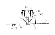
도 7 및 도 8에 따른 횡단면도에 도시된 바와 같이, 평형면으로 형성한 기부판(1)의 반사기는 중앙에 대해 오프셋(offset) 되어 놓인 위치에서 오목한 만입부 또는 이른바 장착점(31)을 가지며, 그 안에는 반사기를 지지체에 나사 회전을 통해 상응하게 고정할 수 있도록 각각 하나의 보어(hole)(33)가 마련된다.As shown in the cross-sectional view according to FIGS. 7 and 8, the reflector of the
마지막으로 전체 안테나 장치는 내부 커버(inner shroud)(35)에 의해 고정 유지된다. 내부 커버(35)는 평형면으로 형성된 기부판(1)으로 된 반사기에서 주연 방향으로 오프셋되어 놓인 래칭(latching)이나 클립핑(clipping) 장치(37)를 가지며, 이는 평형면을 형성한 기부판(1)으로 된 반사기(1) 내의 상응하는 펀칭 또는 개구 내에 삽입될 수 있다. 체결된 상태에서 래칭 장치(37)는 반사기로 된 평형면을 형성한 기부판(1) 내의 펀칭부를 후속 래칭하여, 다른 조립 단계없이 안테나 및 내부 커버(35)가 확실하게 고정 유지된다.Finally, the entire antenna arrangement is held fixed by an
내부 커버(35)는 하부로 컵 형태의 방사기 요소 내로 결합하는 중앙 고정 부분(holding section)(37a)을 중앙에 포함하도록 구성되는데, 중앙 고정부(37a)의 반사기측 전면(end face)(37b)은 방사기를 삽입된 위치에 고정한다. 내부 커버의 반사기측 전면(37b)은 내부 커버에 대향하여 놓인 방사기(15) 측 튜브 형태의 제 2 결합 요소(15c)의 상부 전면과 접촉한다. 내부 커버(35)를 통해 방사기(15)는 축 방향 밀림과 반경 방향 기울기에 대해 고정하여 안전하게 한다.The
마지막으로, 이른바 외부 커버(outer shroud)(41)는 전체적으로 덮여져서 삽입될 수 있으며, 외부 커버(41)도 내부에 놓인 래칭 또는 클립핑 장치(37)를 통해 예를 들어, 내부 커버(35)의 단차 견부에 마련된 개구 또는 반사기인 평형면으로 형성한 기부판(1)의 개구 내에 래칭될 수 있고, 더욱이, 상응하는 래칭 또는 클립핑 장치가 개구를 통해 연장되고 내부 커버 또는 반사기로 된 평형면을 형성한 기부판(1)의 상응하는 재료 부분 후방에서 래칭 될 수 있다. 외부 커버(41)는 반사기로 된 평형면을 형성한 기부판(1)을 포함하여 전체적으로 덮여지도록 구성된다.Finally, the so-called
내부 및 외부 커버(35, 41)는 전자기 방사(elctromagnetic beam)를 위한 전송되는 주파수 범위에서 통과 가능한 하나의 재료로 제조된다.The inner and
마지막으로, 방사기(15)가 상이한 실시예에서 원래부터 도전성 재료로 구성되어야 하는 것이 아니라, 예를 들어 플라스틱과 같은 비 도전성 재료로 형성될 수도 있다. 이러한 경우에, 방사기(15)의 내부면 또는 외부면에 또는 다른 방법으로 적절한 전기도전성 층이 형성되거나 또는 구성한다.Finally, the
Claims (23)
Translated fromKoreanApplications Claiming Priority (3)
| Application Number | Priority Date | Filing Date | Title |
|---|---|---|---|
| DE10359605ADE10359605B4 (en) | 2003-12-18 | 2003-12-18 | Broadband antenna |
| DE10359605.4 | 2003-12-18 | ||
| PCT/EP2004/012211WO2005060048A1 (en) | 2003-12-18 | 2004-10-28 | Broadband antenna, in particular omnidirectional antenna |
Publications (2)
| Publication Number | Publication Date |
|---|---|
| KR20060117325A KR20060117325A (en) | 2006-11-16 |
| KR101083142B1true KR101083142B1 (en) | 2011-11-11 |
Family
ID=34683545
Family Applications (1)
| Application Number | Title | Priority Date | Filing Date |
|---|---|---|---|
| KR1020067009654AExpired - Fee RelatedKR101083142B1 (en) | 2003-12-18 | 2004-10-28 | Broadband antenna |
Country Status (9)
| Country | Link |
|---|---|
| EP (1) | EP1695416B1 (en) |
| KR (1) | KR101083142B1 (en) |
| CN (1) | CN2718805Y (en) |
| AT (1) | ATE397796T1 (en) |
| BR (1) | BRPI0417667A (en) |
| DE (2) | DE10359605B4 (en) |
| ES (1) | ES2305868T3 (en) |
| TW (1) | TW200522433A (en) |
| WO (1) | WO2005060048A1 (en) |
Families Citing this family (17)
| Publication number | Priority date | Publication date | Assignee | Title |
|---|---|---|---|---|
| JP2006186945A (en) | 2004-12-28 | 2006-07-13 | Toyota Motor Corp | Antenna device and communication method using the same |
| DE102008057505A1 (en)* | 2008-11-15 | 2010-08-19 | Festo Ag & Co. Kg | Microwave position measuring device |
| CN101694904B (en)* | 2009-10-16 | 2011-09-28 | 中国联合网络通信集团有限公司 | All-around top absorbing antenna used in indoor distribution system of mobile communication network |
| DE102010011867B4 (en) | 2010-03-18 | 2011-12-22 | Kathrein-Werke Kg | Broadband omnidirectional antenna |
| DE102011113725A1 (en)* | 2011-09-17 | 2013-03-21 | Volkswagen Aktiengesellschaft | Multi-range antenna for a motor vehicle |
| CN102717167B (en)* | 2012-07-04 | 2016-05-25 | 贵州航天电子科技有限公司 | A kind of electronic fuse antenna radiator vacuum brazing assembling and positioning method |
| DE102013012308A1 (en) | 2013-07-24 | 2015-01-29 | Kathrein-Werke Kg | Broadband omnidirectional antenna |
| CN103904418B (en)* | 2014-03-06 | 2016-05-04 | 宁波成电泰克电子信息技术发展有限公司 | A kind of omnidirectional terminal antenna |
| CN106663861B (en) | 2014-07-17 | 2019-11-15 | 胡贝尔和茹纳股份公司 | Antenna device and connector for antenna device |
| DE102015003579A1 (en) | 2015-03-19 | 2016-09-22 | Kathrein-Werke Kg | RF connector for solderless contacting of a coaxial cable |
| DE102016114093B4 (en) | 2016-07-29 | 2020-01-16 | Huber + Suhner Ag | Broadband omnidirectional antenna, in particular for rail vehicles and such a rail vehicle |
| DE102017101677A1 (en) | 2017-01-27 | 2018-08-02 | Kathrein-Werke Kg | Broadband omnidirectional antenna |
| CN108123206A (en)* | 2017-12-20 | 2018-06-05 | 深圳市华信天线技术有限公司 | A kind of antenna mounting seat and antenna |
| CN110474157B (en)* | 2019-08-27 | 2020-06-30 | 南京邮电大学 | Mobile communication frequency band printing monopole antenna |
| CN114696071B (en)* | 2020-12-28 | 2024-07-09 | 电连技术股份有限公司 | Sucker antenna with high gain and wide frequency band |
| KR102449600B1 (en) | 2021-06-01 | 2022-10-04 | 국민대학교산학협력단 | Array antenna with shorting pin |
| DE102023206601A1 (en) | 2023-07-12 | 2025-01-16 | Vega Grieshaber Kg | measuring device with cylindrical monopole antenna |
Family Cites Families (8)
| Publication number | Priority date | Publication date | Assignee | Title |
|---|---|---|---|---|
| US2511849A (en)* | 1950-06-20 | Broad band antenna | ||
| GB580812A (en)* | 1943-12-06 | 1946-09-20 | Standard Telephones Cables Ltd | Improvements in arrangements for coupling wide frequency band antennae to transmission lines |
| US2501020A (en)* | 1945-11-06 | 1950-03-21 | Us Sec War | Antenna structure |
| US4074268A (en)* | 1976-06-21 | 1978-02-14 | Hoffman Electronics Corporation | Electronically scanned antenna |
| US4890116A (en)* | 1986-04-09 | 1989-12-26 | Shakespeare Company | Low profile, broad band monopole antenna |
| US4972196A (en)* | 1987-09-15 | 1990-11-20 | Board Of Trustees Of The Univ. Of Illinois | Broadband, unidirectional patch antenna |
| US5451968A (en)* | 1992-11-19 | 1995-09-19 | Solar Conversion Corp. | Capacitively coupled high frequency, broad-band antenna |
| US20030103008A1 (en)* | 2001-12-05 | 2003-06-05 | Tom Petropoulos | In-building low profile antenna |
- 2003
- 2003-12-18DEDE10359605Apatent/DE10359605B4/ennot_activeExpired - Fee Related
- 2004
- 2004-04-15CNCNU2004200364989Upatent/CN2718805Y/ennot_activeExpired - Lifetime
- 2004-10-28ESES04790981Tpatent/ES2305868T3/ennot_activeExpired - Lifetime
- 2004-10-28KRKR1020067009654Apatent/KR101083142B1/ennot_activeExpired - Fee Related
- 2004-10-28ATAT04790981Tpatent/ATE397796T1/ennot_activeIP Right Cessation
- 2004-10-28BRBRPI0417667-7Apatent/BRPI0417667A/ennot_activeIP Right Cessation
- 2004-10-28WOPCT/EP2004/012211patent/WO2005060048A1/enactiveIP Right Grant
- 2004-10-28EPEP04790981Apatent/EP1695416B1/ennot_activeExpired - Lifetime
- 2004-10-28DEDE502004007336Tpatent/DE502004007336D1/ennot_activeExpired - Lifetime
- 2004-11-25TWTW093136231Apatent/TW200522433A/ennot_activeIP Right Cessation
Also Published As
| Publication number | Publication date |
|---|---|
| EP1695416B1 (en) | 2008-06-04 |
| CN2718805Y (en) | 2005-08-17 |
| TWI351785B (en) | 2011-11-01 |
| WO2005060048A1 (en) | 2005-06-30 |
| ES2305868T3 (en) | 2008-11-01 |
| KR20060117325A (en) | 2006-11-16 |
| TW200522433A (en) | 2005-07-01 |
| ATE397796T1 (en) | 2008-06-15 |
| DE10359605A1 (en) | 2005-07-28 |
| BRPI0417667A (en) | 2007-04-03 |
| DE10359605B4 (en) | 2006-05-24 |
| EP1695416A1 (en) | 2006-08-30 |
| DE502004007336D1 (en) | 2008-07-17 |
Similar Documents
| Publication | Publication Date | Title |
|---|---|---|
| KR101083142B1 (en) | Broadband antenna | |
| US7132995B2 (en) | Antenna having at least one dipole or an antenna element arrangement similar to a dipole | |
| US6169523B1 (en) | Electronically tuned helix radiator choke | |
| US7027004B2 (en) | Omnidirectional broadband antenna | |
| US6137445A (en) | Antenna apparatus for mobile terminal | |
| KR100588765B1 (en) | Circular Polarization Dielectric Resonator Antenna | |
| FI113217B (en) | Dual acting antenna and radio | |
| KR101085889B1 (en) | Wideband dipole antenna | |
| KR101743487B1 (en) | Broadband omnidirectional antenna | |
| US6567045B2 (en) | Wide-angle circular polarization antenna | |
| US3919710A (en) | Turnstile and flared cone UHF antenna | |
| JPH06268429A (en) | Adjustable beam tilt antenna | |
| CN110637394B (en) | Vehicle-mounted antenna device | |
| CN103403961A (en) | Multiband reception antenna for the combined reception of satellite signals and terrestrially emitted radio signals | |
| CN108365330B (en) | Broadband omnidirectional antenna | |
| JP4782203B2 (en) | Ultra-small built-in antenna | |
| CN1663075A (en) | Dual polarization dual band radiation device | |
| EP1653558A1 (en) | Antenna | |
| US20040119657A1 (en) | Stubby, multi-band, antenna having a large-diameter high frequency radiating/receiving element surrounding a small-diameter low frequency radiating/receiving element | |
| AU733260B2 (en) | Antenna for portable radio unit | |
| JP2009060158A (en) | Short back fire antenna | |
| KR100726025B1 (en) | Satellite DMB onboard antenna | |
| JP4105408B2 (en) | Sleeve antenna | |
| KR100575777B1 (en) | Wifi broadband antenna | |
| JP3510961B2 (en) | Wide-angle circularly polarized antenna |
Legal Events
| Date | Code | Title | Description |
|---|---|---|---|
| P11-X000 | Amendment of application requested | St.27 status event code:A-2-2-P10-P11-nap-X000 | |
| P13-X000 | Application amended | St.27 status event code:A-2-2-P10-P13-nap-X000 | |
| PA0105 | International application | St.27 status event code:A-0-1-A10-A15-nap-PA0105 | |
| PG1501 | Laying open of application | St.27 status event code:A-1-1-Q10-Q12-nap-PG1501 | |
| R18-X000 | Changes to party contact information recorded | St.27 status event code:A-3-3-R10-R18-oth-X000 | |
| A201 | Request for examination | ||
| PA0201 | Request for examination | St.27 status event code:A-1-2-D10-D11-exm-PA0201 | |
| E902 | Notification of reason for refusal | ||
| PE0902 | Notice of grounds for rejection | St.27 status event code:A-1-2-D10-D21-exm-PE0902 | |
| E13-X000 | Pre-grant limitation requested | St.27 status event code:A-2-3-E10-E13-lim-X000 | |
| P11-X000 | Amendment of application requested | St.27 status event code:A-2-2-P10-P11-nap-X000 | |
| P13-X000 | Application amended | St.27 status event code:A-2-2-P10-P13-nap-X000 | |
| E701 | Decision to grant or registration of patent right | ||
| PE0701 | Decision of registration | St.27 status event code:A-1-2-D10-D22-exm-PE0701 | |
| GRNT | Written decision to grant | ||
| PR0701 | Registration of establishment | St.27 status event code:A-2-4-F10-F11-exm-PR0701 | |
| PR1002 | Payment of registration fee | St.27 status event code:A-2-2-U10-U12-oth-PR1002 Fee payment year number:1 | |
| PG1601 | Publication of registration | St.27 status event code:A-4-4-Q10-Q13-nap-PG1601 | |
| FPAY | Annual fee payment | Payment date:20141104 Year of fee payment:4 | |
| PR1001 | Payment of annual fee | St.27 status event code:A-4-4-U10-U11-oth-PR1001 Fee payment year number:4 | |
| LAPS | Lapse due to unpaid annual fee | ||
| PC1903 | Unpaid annual fee | St.27 status event code:A-4-4-U10-U13-oth-PC1903 Not in force date:20151108 Payment event data comment text:Termination Category : DEFAULT_OF_REGISTRATION_FEE | |
| R17-X000 | Change to representative recorded | St.27 status event code:A-5-5-R10-R17-oth-X000 | |
| P22-X000 | Classification modified | St.27 status event code:A-4-4-P10-P22-nap-X000 | |
| PC1903 | Unpaid annual fee | St.27 status event code:N-4-6-H10-H13-oth-PC1903 Ip right cessation event data comment text:Termination Category : DEFAULT_OF_REGISTRATION_FEE Not in force date:20151108 |