KR101083108B1 - The inspection apparatus for nuclear fuel rod assembly - Google Patents
The inspection apparatus for nuclear fuel rod assemblyDownload PDFInfo
- Publication number
- KR101083108B1 KR101083108B1KR1020090058579AKR20090058579AKR101083108B1KR 101083108 B1KR101083108 B1KR 101083108B1KR 1020090058579 AKR1020090058579 AKR 1020090058579AKR 20090058579 AKR20090058579 AKR 20090058579AKR 101083108 B1KR101083108 B1KR 101083108B1
- Authority
- KR
- South Korea
- Prior art keywords
- ultrasonic
- nuclear fuel
- ultrasonic transducer
- transmitting
- receiving
- Prior art date
- Legal status (The legal status is an assumption and is not a legal conclusion. Google has not performed a legal analysis and makes no representation as to the accuracy of the status listed.)
- Expired - Fee Related
Links
Images


Classifications
- G—PHYSICS
- G21—NUCLEAR PHYSICS; NUCLEAR ENGINEERING
- G21C—NUCLEAR REACTORS
- G21C17/00—Monitoring; Testing ; Maintaining
- G21C17/06—Devices or arrangements for monitoring or testing fuel or fuel elements outside the reactor core, e.g. for burn-up, for contamination
- G21C17/07—Leak testing
- G—PHYSICS
- G01—MEASURING; TESTING
- G01M—TESTING STATIC OR DYNAMIC BALANCE OF MACHINES OR STRUCTURES; TESTING OF STRUCTURES OR APPARATUS, NOT OTHERWISE PROVIDED FOR
- G01M3/00—Investigating fluid-tightness of structures
- G—PHYSICS
- G21—NUCLEAR PHYSICS; NUCLEAR ENGINEERING
- G21C—NUCLEAR REACTORS
- G21C17/00—Monitoring; Testing ; Maintaining
- G21C17/002—Detection of leaks
- Y—GENERAL TAGGING OF NEW TECHNOLOGICAL DEVELOPMENTS; GENERAL TAGGING OF CROSS-SECTIONAL TECHNOLOGIES SPANNING OVER SEVERAL SECTIONS OF THE IPC; TECHNICAL SUBJECTS COVERED BY FORMER USPC CROSS-REFERENCE ART COLLECTIONS [XRACs] AND DIGESTS
- Y02—TECHNOLOGIES OR APPLICATIONS FOR MITIGATION OR ADAPTATION AGAINST CLIMATE CHANGE
- Y02E—REDUCTION OF GREENHOUSE GAS [GHG] EMISSIONS, RELATED TO ENERGY GENERATION, TRANSMISSION OR DISTRIBUTION
- Y02E30/00—Energy generation of nuclear origin
- Y02E30/30—Nuclear fission reactors
Landscapes
- Physics & Mathematics (AREA)
- Engineering & Computer Science (AREA)
- Plasma & Fusion (AREA)
- General Engineering & Computer Science (AREA)
- High Energy & Nuclear Physics (AREA)
- General Physics & Mathematics (AREA)
- Monitoring And Testing Of Nuclear Reactors (AREA)
Abstract
Translated fromKoreanDescription
Translated fromKorean이 발명은 원자력 발전 분야에 관한 것으로서, 좀더 세부적으로 말하자면 핵 연료봉의 한쪽 측면으로만 송신 초음파 탐촉자와 수신 초음파 탐촉자를 구비한 송수신 초음파 탐촉자 모듈을 핵 연료봉의 한쪽 측면으로만 접근시켜서 송신 초음파 탐촉자로부터 초음파를 경사지게 송신하고 이를 수신 초음파 탐촉자를 이용하여 수신하여 핵연료봉의 누설 여부를 확인하며, 핵연료 집합체의 한쪽 측면으로만 접근하여도 검사가 가능하기 때문에 다수개의 송수신 초음파 탐촉자 모듈을 배열하여 핵연료 집합체를 1회의 왕복이송만으로도 한번에 검사할 수 있도록 함으로써 검사 속도를 획기적으로 증가시킬 수 있는, 핵연료 집합체 검사 장치에 관한 것이다.The present invention relates to the field of nuclear power generation, and more specifically, to transmit and receive ultrasonic transducer module having a transmitting ultrasonic transducer and a receiving ultrasonic transducer to only one side of the nuclear fuel rod, to approach only one side of the nuclear fuel rod, so that the ultrasonic wave from the transmitting ultrasonic transducer Is transmitted at an angle and received using a receiving ultrasonic probe to check whether the fuel rod is leaking, and can be inspected even by approaching only one side of the fuel assembly, so that a plurality of transmitting and receiving ultrasonic transducer modules are arranged to arrange the fuel assembly once. The present invention relates to a nuclear fuel assembly inspection apparatus that can dramatically increase the inspection speed by allowing inspection at a time with only a round trip.
원자력 발전은 원자로 내부에서 핵연료를 이용하여 핵분열시 생성되는 에너지를 이용하여 1차 냉각수를 가열하고, 가열된 에너지를 이용하여 증기발생기에서 2 차 냉각수로 에너지를 전달하여 발생된 증기를 이용하여 증기터빈에서 회전에너지를 변환하여 발전기에서 전기를 생산하는 구조로 이루어진다.Nuclear power generation uses the fuel generated inside the reactor to heat the primary cooling water using the energy generated during nuclear fission, and transfers the energy from the steam generator to the secondary cooling water using the heated energy. It consists of a structure that produces electricity from a generator by converting rotational energy in.
원자로 내부에 배열된 핵연료는, 도 1에 도시되어 있는 바와 같은 핵연료 집 합체(100)를 단위로 구성되어 있으며, 하나의 핵연료 집합체(100)은 다수개의 핵연료봉(105)으로 구성된다.The nuclear fuel arranged inside the reactor is composed of a
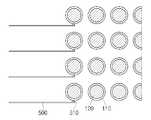
도 2는 일반적인 핵연료봉의 배열 상태를 나타내는 도면으로서, 도 2에 도시되어 있는 바와 같이, 핵연료봉(105)은 17행과 17열로 배열되는 구조로 이루어진다. 그리고, 하나의 핵연료봉(105)은 펠렛(120) 단위의 우라늄이 1mm 두께의 얇은 지르코늄 합금 피복관(110)으로 덮여 있어서 외부의 손상으로부터 보호되도록 하고 방사능 누출이 되지 않도록 하는 구조로 이루어진다.FIG. 2 is a view illustrating an arrangement of a general fuel rod, and as shown in FIG. 2, the
핵연료 집합체(100)는 원자로 내에서 고온 고압의 유체 흐름으로 인하여 진동이 발생하고, 지지 격자(140)와의 마모로 인해서 핵연료봉(105)의 피복관(110)이 파손될 수도 있다. 이와 같이 핵연료봉(105)의 피복관(110)이 파손되면 핵연료로부터 방사능이 과다하게 누출되어 1차 냉각수의 오염이 심화되며, 파손이 심할 경우에는 핵연료봉(105)이 탈락되어 원자로 내부에서 이동하게 됨으로써 심각한 사태를 초래할 수도 있다.The
따라서 원자력발전소 가동중 검사기간 동안 핵연료 집합체(100)는 주기적으로 누설 여부를 확인하여 그 건전성을 유지할 수 있도록 하여야 한다.Therefore, during the inspection period during operation of the nuclear power plant, the
핵연료 집합체(100)의 건전성을 평가하는 방법으로서는, 시핑 테스트, 육안검사, 그리고 초음파 검사방법 등이 사용되고 있다.As a method for evaluating the integrity of the
상기한 시핑 테스트는 핵연료 집합체(100)를 별도의 수조에 담그고 물의 방사능 준위를 측정하여 누설여부를 확인하는 방법으로서, 핵연료 집합체(100) 단위로 검사가 이루어지므로, 핵연료 집합체(100)의 방사능 준위가 높을 경우에 핵연료 집합체(100)를 분리하여 핵연료봉(105) 단위로 검사를 다시 하여야 하므로 많은 시간과 노력이 소요되는 문제점이 있다. 또한 누설로 인하여 수조에 있는 물의 방사능 준위가 높아지게 되면 다음에 검사하게 될 검사대상을 정확하게 검사할 수 없는 문제점도 있다.The shiping test is a method of immersing the
상기한 육안검사는 핵연료봉(105)의 외형적 형태를 육안으로 관찰하는 방법으로서, 단순히 핵연료봉(105)의 외형적 형태만을 관찰하는 것이므로, 육안으로 볼 수 있는 심각한 손상이 아니고 미세한 구멍이 발생한 경우에는 육안으로 검출을 할 수 없을 뿐만 아니라, 핵연료 집합체(100)의 외부쪽에 배열된 핵연료봉(105)만 검사가 가능할 뿐 핵연료 집합체(100)의 내부쪽에 있는 핵연료봉(105)은 검사할 수 없어서 사각지대가 되어 버리는 문제점이 있다.The above-described visual inspection is a method of visually observing the external shape of the
상기한 방법들의 문제점으로 인하여 초음파를 사용한 검사 방법이 가장 보편적으로 사용되고 있으나, 검사 기법상의 한계로 인하여 핵연료 집합체(100)에 있는 핵연료봉(105) 단위로 검사를 시행하므로 검사시간이 많이 소요되는 단점이 있어왔다.Due to the problems of the above methods, the inspection method using ultrasonic waves is most commonly used, but due to limitations in the inspection technique, inspection time is required because the inspection is performed in units of
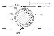
기존에 사용되던 초음파 검사방법에서 파손여부를 확인하는 방법으로서는 핵연료 펠렛(120)과 피복관(110)의 사이에 물이 존재하느냐 존재하지 않느냐에 의하여 판단을 한다. 건전한 핵연료봉(105)은 피복관(110)과 연료 펠렛(120)의 사이에 간극이 존재하고 그 사이에 공기가 있는데 반하여, 피복관(110)이 손상이 된 핵연료봉(105)은 손상된 부위로 물이 침수하여, 도 3에 도시되어 있는 바와 같이, 피복관(110)과 연료 펠렛(120)의 사이에 물(130)이 채워지게 되기 때문이다. 따라서, 연료봉(105)의 건전한 경우와 파손된 경우는 피복관(110)과 연료 펠렛(120)의 사이에 물(130)이 있는지 없는지에 의하여 알 수 있다.As a method of confirming whether or not the damage in the conventional ultrasonic test method is used, it is determined by the presence or absence of water between the
이와 같이 물의 존재 여부를 이용하여 파손 여부를 확인하는 종래의 초음파 검사 방법이 도 4a 및 도 4b에 도시되어 있다. 도 4a 및 도 4b에 도시되어 있는 바와 같이, 종래의 초음파 검사방법은, 연료봉(105)의 한쪽에 초음파를 수직으로 송신하는 송신 탐촉자(210)를 배치하고, 그 반대쪽에 초음파를 수신하는 수신 탐촉자(220)를 배열하고, 핵연료봉(105)의 한쪽 측면에서 시작하여 이동하면서 검사를 수행하는 구조로 이루어진다.As described above, a conventional ultrasonic test method for checking whether the water is broken using water is illustrated in FIGS. 4A and 4B. As shown in Figs. 4A and 4B, in the conventional ultrasonic inspection method, a
도 4a는 종래의 건전한 핵 연료봉의 초음파 검사방법을 보여주는 도면으로서, 건전한 핵 연료봉(105)일 경우에는 피복관(110)과 연료 펠렛(120)과의 사이에 공기층(135)이 존재하므로 송신 탐촉자(210)에서 생성된 초음파가 피복관(110)내에서만 전파하면서 진행하므로 초음파가 연료 펠렛(120)으로 전파될 수 없다. 따라서 산란되는 초음파 에너지의 양이 적으므로 수신 탐촉자(220)로 전달되어 수신되는 초음파의 크기가 상대적으로 크게 된다. 수신 탐촉자(220)에 수신되어 화면(250)에 나타나는 초음파 신호(230)의 형상과 크기는 도 4b에 도시되어 있다.4A is a view illustrating an ultrasonic inspection method of a conventional nuclear fuel rod. In the case of the nuclear
도 5a는 종래의 파손된 핵 연료봉의 초음파 검사방법을 보여주는 도면으로서, 핵연료봉(105)이 손상되어 핵연료봉(105)이 물이 침수하게 되므로, 송신 탐촉자(210) 및 수신 탐촉자(220)가 손상된 핵 연료봉(105)을 사이에 두고 검사를 진행하게 되면 송신 탐촉자에(210)서 발생된 초음파가 핵 연료봉(105)에 도달하고 내부에 존재하는 물(130) 때문에 초음파가 피복관(110)으로도 전파되지만 연료 펠 렛(120)으로도 전파된다. 따라서 수신 탐촉자(220)로 전달되는 최종 초음파 에너지의 크기가 줄어들어서 초음파 신호(230)의 진폭이 도 5b에 나타난 바와 같이 감소하게 된다.5A is a view illustrating an ultrasonic inspection method of a conventional broken nuclear fuel rod, since the
따라서 기존의 초음파 검사 방법에서는 수신된 초음파의 상대적 크기를 비교함으로써 핵 연료봉(105)의 파손여부를 확인할 수 있다.Therefore, in the conventional ultrasonic test method, it is possible to check whether the
그러나 이러한 종래의 초음파 검사 방법은 초음파 탐촉자를 공간이 협소한 핵연료봉(105)의 양측면에서 접근하여야 하므로 한번에 한개의 핵연료봉(105)만을 검사할 수 있어서, 한개의 핵연료 집합체(100)를 검사하기 위해서는 17회의 검사를 수행하여야 하는 문제점이 있다.However, since the conventional ultrasonic inspection method needs to approach the ultrasonic probe from both sides of the narrow
또한 종래의 초음파 검사방법은 수신된 초음파 신호(230)의 크기 차이가 현저하지 않을 경우에는 핵연료봉(105)의 파손 여부를 판정하기가 어렵다는 문제점이 있다.In addition, the conventional ultrasonic test method has a problem that it is difficult to determine whether the
본 발명의 목적은 상기한 바와 같은 종래의 문제점을 해결하기 위한 것으로서, 핵 연료봉의 한쪽 측면으로만 송신 초음파 탐촉자와 수신 초음파 탐촉자를 구비한 송수신 초음파 탐촉자 모듈을 핵 연료봉의 한쪽 측면으로만 접근시켜서 송신 초음파 탐촉자로부터 초음파를 경사지게 송신하고 이를 수신 초음파 탐촉자를 이용하여 수신하여 핵연료봉의 누설 여부를 확인하는, 핵연료 집합체 검사 장치를 제공하는 데 있다.SUMMARY OF THE INVENTION An object of the present invention is to solve the conventional problems as described above, and transmit and receive an ultrasonic transducer module having a transmitting ultrasonic probe and a receiving ultrasonic transducer to only one side of the nuclear fuel rod by approaching only one side of the nuclear fuel rod. The present invention provides a nuclear fuel assembly inspection apparatus for inclinedly transmitting an ultrasonic wave from an ultrasonic probe and receiving the ultrasonic wave using a receiving ultrasonic probe to check whether a nuclear fuel rod is leaked.
이 발명의 다른 목적은, 핵연료 집합체의 한쪽 측면으로만 접근하여도 검사가 가능하기 때문에 다수개의 송수신 초음파 탐촉자 모듈을 배열하여 핵연료 집합체를 1회의 왕복이송만으로도 한번에 검사할 수 있도록 함으로써 검사 속도를 획기적으로 증가시킬 수 있는, 핵연료 집합체 검사 장치를 제공하는 데 있다.Another object of the present invention is that inspection can be performed even by approaching only one side of the fuel assembly, so that a plurality of transceiving ultrasonic transducer modules can be arranged so that the fuel assembly can be inspected at once with only one round trip. It is to provide a fuel assembly inspection apparatus that can be increased.
상기한 목적을 달성하기 위한 수단으로서 이 발명의 구성은, 제어 및 초음파 신호수집을 위한 컴퓨터와, 상기한 제어 및 초음파 신호수집용 컴퓨터에 연결되어 있는 구동부 제어용 제어기와, 송신 초음파 탐촉자와 수신 초음파 탐촉자가 핵 연료봉의 길이방향으로 배열되고 상기한 송신 초음파 탐촉자로부터 수신 초음파 탐촉자가 배치된 방향으로 경사지게 초음파를 발생하고 초음파가 핵 연료봉으로 전파되었을 때 초음파가 수신되는 각도에 수신 초음파 탐촉자가 설치되어 있는 검사대와, 상기한 검사대로부터 수신되는 초음파 신호를 화면에 표시하는 초음파 송수신기를 포함하여 이루어진다.As a means for achieving the above object, the configuration of the present invention includes a computer for control and ultrasonic signal collection, a controller for controlling a drive connected to the computer for control and ultrasonic signal collection, a transmitting ultrasonic probe and a receiving ultrasonic probe. Table is arranged in the longitudinal direction of the nuclear fuel rod and the ultrasonic wave generator generates the ultrasonic wave obliquely from the transmitting ultrasonic probe in the direction in which the ultrasonic wave is placed, and the ultrasonic wave transducer is installed at the angle at which the ultrasonic wave is received when the ultrasonic wave propagates to the nuclear fuel rod. And an ultrasonic transceiver for displaying the ultrasonic signal received from the inspection table on the screen.
이 발명의 구성은, 상기한 검사대는 핵연료 저장조의 수중에 설치되면 바람직하다.The structure of this invention is preferable when the said test stand is installed in the water of a nuclear fuel storage tank.
이 발명의 구성은, 상기한 검사대는, 송수신 초음파 탐촉자 모듈과, 상기한 송수신 초음파 탐촉자 모듈이 배열된 이송부와, 상기한 이송부를 핵연료 집합체로 전진 및 후진할 수 있는 모터를 구비한 구동부와, 상기한 이송부와 구동부의 사이에 설치되어 있는 레일과, 핵연료 저장조에서 검사대가 랙에 안착하여 안정되게 고정할 수 있는 지지대를 포함하여 이루어진다.According to a configuration of the present invention, the test table includes a drive unit including a transmission / reception ultrasonic transducer module, a transfer unit in which the transmission / reception ultrasonic transducer module is arranged, and a motor capable of advancing and reversing the transfer unit to a fuel assembly; The rail is provided between the transfer unit and the drive unit, and the support in the nuclear fuel storage tank includes a support that can be securely fixed to the rack seated.
이 발명의 구성은, 상기한 이송부는 수중에서 설치되어 내부로 물이 침수하지 않도록 방수 처리가 되어 있으면 바람직하다.It is preferable that the structure of this invention is provided that the said conveyance part is provided in water, and is waterproofed so that water may not be submerged inside.
이 발명의 구성은, 상기한 송수신 초음파 탐촉자 모듈은 핵 연료봉의 수량과 동일한 수량으로 설치되면 바람직하다.The configuration of the present invention is preferably such that the above-mentioned transceiving ultrasonic probe module is installed in the same quantity as the quantity of nuclear fuel rods.
이 발명의 구성은, 상기한 구동부에는 상기한 이송부를 이송하기 위한 구동력을 제공하는 모터와 이송거리를 측정하기 위한 엔코더를 구비하면 바람직하다.It is preferable that the structure of this invention is equipped with the said drive part and the motor which provides the drive force for conveying the said conveyance part, and the encoder for measuring a conveyance distance.
이 발명의 구성은, 송수신 초음파 탐촉자 모듈은 송신 초음파 탐촉자와 수신 초음파 탐촉자가 수직으로 배열되며, 초음파 신호의 수신범위내에서 송신 초음파 탐촉자와 수신 초음파 탐촉자의 간격을 조절하여 수신되는 초음파의 크기를 변경하면 바람직하다.In the configuration of the present invention, the transmitting and receiving ultrasonic transducer module vertically arranged the transmitting ultrasonic transducer and the receiving ultrasonic transducer, and changes the size of the received ultrasonic wave by adjusting the interval between the transmitting ultrasonic transducer and the receiving ultrasonic transducer within the receiving range of the ultrasonic signal. Is preferable.
이 발명의 구성은, 상기한 송수신 초음파 탐촉자 모듈은 송신 초음파 탐촉자와 수신 초음파 탐촉자가 핵 연료봉의 길이 방향에 수직으로 배열되면 바람직하다.In the configuration of the present invention, it is preferable that the transmitting and receiving ultrasonic transducer module is arranged such that the transmitting ultrasonic transducer and the receiving ultrasonic transducer are arranged perpendicular to the longitudinal direction of the nuclear fuel rod.
이 발명은, 핵 연료봉의 한쪽 측면으로만 송신 초음파 탐촉자와 수신 초음파 탐촉자를 구비한 송수신 초음파 탐촉자 모듈을 핵 연료봉의 한쪽 측면으로만 접근시켜서 송신 초음파 탐촉자로부터 초음파를 경사지게 송신하고 이를 수신 초음파 탐촉자를 이용하여 수신하여 핵연료봉의 누설 여부를 확인하며, 핵연료 집합체의 한쪽 측면으로만 접근하여도 검사가 가능하기 때문에 다수개의 송수신 초음파 탐촉자 모듈을 배열하여 핵연료 집합체를 1회의 왕복이송만으로도 한번에 검사할 수 있도록 함으로써 검사 속도를 획기적으로 증가시킬 수 있는, 효과를 갖는다.The present invention provides a transmitting and receiving ultrasonic transducer module having a transmitting ultrasonic transducer and a receiving ultrasonic transducer to only one side of the nuclear fuel rod, approaching only one side of the nuclear fuel rod to obliquely transmit ultrasonic waves from the transmitting ultrasonic probe and using the receiving ultrasonic transducer. By checking the leakage of the fuel rods and inspecting them by approaching only one side of the fuel assembly.As a result, the plurality of transceiving ultrasonic transducer modules can be arranged so that the fuel assembly can be inspected at once with only one round trip. Has the effect, which can dramatically increase the speed.
이하, 이 발명이 속하는 기술분야에서 통상의 지식을 가진 자가 이 발명을 용이하게 실시할 수 있을 정도로 상세히 설명하기 위하여, 이 발명의 가장 바람직한 실시예를 첨부된 도면을 참조로 하여 상세히 설명하기로 한다. 이 발명의 목적, 작용, 효과를 포함하여 기타 다른 목적들, 특징점들, 그리고 동작상의 이점들이 바람직한 실시예의 설명에 의해 보다 명확해질 것이다.DETAILED DESCRIPTION OF THE PREFERRED EMBODIMENTS Hereinafter, the present invention will be described in detail with reference to the accompanying drawings in order to describe in detail enough to enable those skilled in the art to easily carry out the present invention. . Other objects, features, and operational advantages, including the purpose, operation, and effect of the present invention will become more apparent from the description of the preferred embodiments.
참고로, 여기에서 개시되는 실시예는 여러가지 실시가능한 예중에서 당업자의 이해를 돕기 위하여 가장 바람직한 실시예를 선정하여 제시한 것일 뿐, 이 발명의 기술적 사상이 반드시 이 실시예에만 의해서 한정되거나 제한되는 것은 아니고, 본 발명의 기술적 사상을 벗어나지 않는 범위내에서 다양한 변화와 부가 및 변경이 가능함은 물론, 균등한 타의 실시예가 가능함을 밝혀 둔다.For reference, the embodiments disclosed herein are only presented by selecting the most preferred embodiment in order to help those skilled in the art from the various possible examples, the technical spirit of the present invention is not necessarily limited or limited only by this embodiment Rather, various changes, additions, and changes are possible within the scope without departing from the spirit of the present invention, as well as other equivalent embodiments.
도 6은 이 발명의 일실시예에 따른 핵연료 집합체 검사 장치의 구성도이고, 도 7은 이 발명의 일실시예에 따른 핵연료 집합체 검사 장치의 검사대의 측면 구성도이고, 도 8은 이 발명의 일실시예에 따른 핵연료 집합체 검사 장치의 송수신 초음파 탐촉자 모듈의 측면 설치구성도이고, 도 9는 이 발명의 일실시예에 따른 핵연료 집합체 검사 장치의 송수신 초음파 탐촉자 모듈의 정면 설치구성도이고, 도 10은 이 발명의 일실시예에 따른 핵연료 집합체 검사 장치의 송수신 초음파 탐촉자 모듈의 평면 설치구성도이다.6 is a configuration diagram of a nuclear fuel assembly inspection apparatus according to an embodiment of the present invention, Figure 7 is a side configuration diagram of the inspection table of the nuclear fuel assembly inspection apparatus according to an embodiment of the present invention, Figure 8 is one of the present invention Figure 9 is a side installation configuration of the ultrasonic transducer module of the nuclear fuel assembly inspection apparatus according to the embodiment, Figure 9 is a front view of the ultrasonic transducer module of the nuclear fuel assembly inspection apparatus according to an embodiment of the present invention, Figure 10 Fig. 1 is a plan view of the transmissive ultrasonic transducer module of the nuclear fuel assembly inspection apparatus according to the embodiment of the present invention.
도 6 내지 도 10에 도시되어 있는 바와 같이, 이 발명의 일실시예에 따른 의 구성은, 제어 및 초음파 신호수집을 위한 컴퓨터(410)와, 상기한 제어 및 초음 파 신호수집용 컴퓨터(410)에 연결되어 있는 구동부 제어용 제어기(420)와, 송신 초음파 탐촉자(510)와 수신 초음파 탐촉자(520)가 핵 연료봉(105)의 길이방향으로 배열되고 상기한 송신 초음파 탐촉자(510)로부터 수신 초음파 탐촉자(520)가 배치된 방향으로 경사지게 초음파를 발생하고 초음파가 핵 연료봉(105)으로 전파되었을 때 초음파가 수신되는 각도에 수신 초음파 탐촉자(520)가 설치되어 있는 검사대(400)와, 상기한 검사대(400)로부터 수신되는 초음파 신호를 화면에 표시하는 초음파 송수신기(430)를 포함하여 이루어진다.As shown in Figure 6 to 10, the configuration of according to an embodiment of the present invention, the
상기한 검사대(400)를 제외한 제어 및 초음파 신호 수집용 컴퓨터(410), 구동부 제어용 제어기(420), 초음파 송수신기(430)는 상기한 검사대(400)와 별도로 설치된다.The control and ultrasonic
원자력 발전소의 핵연료 집합체(100)는 검사를 위하여 원자로가 설치된 시설의 주변에 있는 핵연료 저장조(도시되지 않음)로 운반이 되며, 이와 같이 핵연료 저장조로 운반된 핵연료 집합체(100)는 물이 가득찬 핵연료 저장조의 수중 랙에 거치됨으로써 물속에 잠겨져 보관이 된다. 상기한 검사대(400)는 이와 같이 핵연료 집합체(100)가 저장된 핵연료 저장조의 수중에 핵연료 집합체(100)와 함께 설치된다. 상기한 검사대(400)를 핵연료 저장조의 비어 있는 랙으로 이동하여 고정시키고, 제어 및 초음파 신호 수집용 컴퓨터(410)와 연결되어 있는 구동부 제어용 제어기(420)와 초음파 송수신 장비(430)에 각각 케이블을 연결함으로써 검사를 위한 준비가 완료된다.The
상기한 검사대(400)는, 송수신 초음파 탐촉자 모듈(500)과, 상기한 송수신 초음파 탐촉자 모듈(500)이 배열된 이송부(440)와, 상기한 이송부(400)를 핵연료 집합체(100)로 전진 및 후진할 수 있는 모터를 구비한 구동부(460)와, 상기한 이송부(440)와 구동부(460)의 사이에 설치되어 있는 레일(450)과, 핵연료 저장조에서 검사대(400)가 랙에 안착하여 안정되게 고정할 수 있는 지지대(470)를 포함하여 이루어진다.The inspection table 400, the transmission and reception
상기한 이송부(440)는 수중에서 설치되어 내부로 물이 침수하지 않도록 방수 처리가 되어 있으며, 송수신 초음파 탐촉자 모듈(500)이 핵 연료봉(105)의 수량과 동일하게 수평으로 배열되어 있다.The
상기한 구동부(460)에는 상기한 이송부(440)를 이송하기 위한 구동력을 제공하는 모터와 이송거리를 측정하기 위한 엔코더를 구비하고 있다.The
상기한 이송부(440)와 구동부(460)의 사이에는 레일(450)이 설치되어 있어서 기어를 이용하여 이송부(440)가 레일(450)을 따라 일직선으로 전진과 후진을 할 수 있도록 제작이 되어 있다.The
상기한 검사대(400)의 설치가 완료됨으로써 검사를 위한 핵연료 집합체(100)가 상기한 검사대(400)가 설치된 곳의 전면에 위치하게 되면, 이송부(440)에 의해 송수신 초음파 탐촉자 모듈(500)이 핵연료 집합체(100)의 핵연료 봉(105)을 한꺼번에 검사를 함으로써 1회 전진 및 후진으로 검사가 완료된다.When the installation of the inspection table 400 is completed, the
상기한 송수신 초음파 탐촉자 모듈(500)은 송신 초음파 탐촉자(510)와 수신 초음파 탐촉자(520)가 핵연료봉(110)의 길이 방향을 따라 수직으로 배열되는 구조로 이루어진다.The transmitting and receiving
상기한 송신 초음파 탐촉자(510)는 핵연료봉(105)의 축방향을 향하여 경사각도로 초음파를 입사할 수 있도록 핵 연료봉(105)의 길이 방향으로 배열된다.The transmitting
상기한 수신 초음파 탐촉자(520)는 상기한 송신 초음파 탐촉자(510)로부터 입사되는 초음파를 수신할 수 있는 경사각도의 위치내에서 핵연료봉(105)의 길이 방향으로 배열된다.The receiving
상기한 구성에 의한, 이 발명의 일실시예에 따른 핵연료 집합체 검사 장치의 작용은 다음과 같다.With the above configuration, the operation of the nuclear fuel assembly inspection apparatus according to the embodiment of the present invention is as follows.
핵 연료봉(105)에 초음파를 입사하고 수신하는 송수신 초음파 탐촉자 모듈(500)의 구동 원리는 도 11 및 도 12에 도시되어 있다.The driving principle of the transceiving
도 11a는 이 발명의 일실시예에 따른 핵연료 집합체 검사 장치의 건전한 핵 연료봉의 검사방법을 보여주는 도면으로서, 핵연료봉(105)이 건전한 연료봉일 경우에 송신 초음파 탐촉자(510)에서 송신된 초음파가 핵연료봉(105)의 피복관(110)을 전파하여 수신 초음파 탐촉자(520)로 수신되는 경로와 초음파 신호를 나타낸다. 건전한 핵 연료봉(105)의 외부로부터 송신 초음파 탐촉자(510)에서 초음파를 경사지게 입사를 시키면 피복관(110)의 내측에는 공기가 충진되어 있으므로 피복관(110)과 공기의 음향 임피던스 차이로 인하여 공기층(135)으로 초음파가 전파될 수 없어 초음파는 피복관(110)의 내부면에서 다시 반사를 하게 된다. 이와 같이 피복관(110)의 내부면에서 반사된 초음파는 다시 외부면으로 방향을 틀고 피복관(110)의 외부면에서 다시 반사되어 내부로 진행하는 거동을 취하면서 진행함으로써 수신 초음파 탐촉자(520)에 초음파가 수신된다.11A is a view showing a method of inspecting a healthy nuclear fuel rod of the nuclear fuel assembly inspection apparatus according to an embodiment of the present invention, when the
수신 초음파 탐촉자(520)에 수신된 초음파 신호는 초음파 송수신기(430)로 전송됨으로써, 도 11b에 도시되어 있는 바와 같이 초음파 송수신기(430)의 화면에는 수신 초음파 신호(230)가 나타나게 된다. 이와 같이 초음파 송수신기(430)의 화면에 수신 초음파 신호(230)가 나타나게 되면 핵연료봉(105)이 건전하다는 것을 확인할 수 있다. 이 경우에, 송신 초음파 탐촉자(510)와 수신 초음파 탐촉자(520)의 배치거리가 짧게 되면 핵연료봉(105)으로부터 수신되는 초음파 신호(230)의 진폭이 월등하게 높아 검사자가 쉽게 파손여부를 판별할 수 있으며, 초음파 신호(230)의 수신범위내에서 송신 초음파 탐촉자(510)와 수신 초음파 탐촉자(520)의 간격을 조절하여 수신되는 초음파의 크기를 변경할 수가 있게 된다.The ultrasonic signal received by the receiving
도 12a는 이 발명의 일실시예에 따른 핵연료 집합체 검사 장치의 파손된 핵 연료봉의 검사방법을 보여주는 도면이다. 핵연료 피복관(110)이 손상되어 핵연료봉(105)의 내부에 물(130)이 들어갔을 경우에, 송신 초음파 탐촉자(510)에서 송신된 초음파는 내부에 물(130)이 충수되어 있으므로 핵연료 피복관(110)의 내부에서 반사되지 않고 물(130)로 투과되고, 이와 같이 물을 투과하여 통과된 초음파는 다시 핵연료 펠렛(120)으로 진행하여 반대면 피복관(110)에서 일부는 핵 연료봉(105)의 외부로 투과되고 일부는 다시 핵 연료봉(105)의 내부로 반사되어 들어온다. 그러나 핵 연료봉(105)의 내부로 반사된 초음파는 에너지가 작을 뿐만 아니라 수신 초음파 탐촉자(520)에서 수신할 수 없는 경로로 각도가 변경되어 있으므로 수신 초음파 탐촉자(520)에서는 어떠한 초음파 에너지도 수신을 할 수 없으므로 도 12b에 도시되어 있는 바와 같이 초음파 송수신기(430)의 화면에는 아무런 수신 초음파 신 호도 나타나지를 않게 된다.12A is a view showing a method of inspecting a broken nuclear fuel rod of the nuclear fuel assembly inspection apparatus according to an embodiment of the present invention. When the
이와 같이 건전한 핵 연료봉(105)에 있어서는 수신 초음파 탐촉자(520)에 초음파가 도달하게 됨으로써 초음파 송수신기(430)의 화면에 초음파 신호(230)가 나타나게 되고, 파손된 핵 연료봉(105)에서는 핵 연료봉(105)의 내부로 초음파가 전파되어 경로가 변경되어 수신 초음파 탐촉자(520)에 초음파 신호가 전혀 수신되지 않게 됨으로써 초음파 송수신기(430)의 화면상에 초음파 신호가 나타나지 않게 된다.As such, in the
상기한 컴퓨터(410)는 이송부(440)의 위치와 초음파 신호를 수집하여, 이와 같이 수집된 신호를 B-Scan 이미지로 표시함으로써 핵 연료봉(105)의 손상 여부를 평가할 수 있도록 한다.The
한편, 상기한 송수신 초음파 탐촉자 모듈(500)은 송신 초음파 탐촉자(510)와 수신 초음파 탐촉자(520)의 배열 방향이 핵 연료봉(105)의 길이 방향이 아닌 길이 방향에 수직으로 배열될 수도 있다.On the other hand, the transmitting and receiving
이상 살펴본 바와 같이 본 발명은 원자력발전소의 원자로에 설치된 핵연료 집합체(100)를 검사하는 장비로서, 송수신 초음파 탐촉자 모듈(500)을 핵 연료봉(105)의 안쪽 측면에 수직으로 배열하여 초음파 사각으로 발생하게 함으로써 핵 연료봉(105)에서 초음파의 전달거리를 최소화하고, 핵 연료봉(105)이 누설하였을때와 건전하였을때의 신호가 분명하게 분간이 되도록 하여 피복관(110)이 파단되어 누설되는 핵 연료봉(105)을 명확하게 찾을 수 있다.As described above, the present invention is a device for inspecting a
또한 본 발명은, 핵연료 집합체(100)내에서 핵 연료봉(105) 사이의 간극이 세밀하게 배열되어 있어도 송수신 초음파 탐촉자 모듈(500)의 1회의 이동만으로 전체 핵 연료봉(105)을 모두 검사할 수 있으므로 검사 속도를 향상할 수 있어서, 원자력발전소 가동중검사 기간중 핵연료 검사에 소요되는 검사기간을 획기적으로 줄일 수 있다.In addition, in the present invention, even if the gaps between the
도 1은 일반적인 핵연료 집합체 및 핵연료봉의 구성도이다.1 is a block diagram of a general fuel assembly and a fuel rod.
도 2는 일반적인 핵연료봉의 배열 상태를 나타내는 평면도이다.2 is a plan view showing the arrangement state of a general nuclear fuel rods.
도 3은 손상된 핵연료봉의 평면 구조도이다.3 is a plan view of the damaged nuclear fuel rods.
도 4a는 종래의 건전한 핵 연료봉의 초음파 검사방법을 보여주는 도면이고, 도 4b는 그의 초음파 신호를 보여주는 도면이다.Figure 4a is a view showing an ultrasonic inspection method of a conventional healthy nuclear fuel rod, Figure 4b is a view showing the ultrasonic signal thereof.
도 5a는 종래의 파손된 핵 연료봉의 초음파 검사방법을 보여주는 도면이고, 도 5b는 그의 초음파 신호를 보여주는 도면이다.Figure 5a is a view showing an ultrasonic inspection method of a conventional broken nuclear fuel rod, Figure 5b is a view showing the ultrasonic signal thereof.
도 6은 이 발명의 일실시예에 따른 핵연료 집합체 검사 장치의 구성도이다.6 is a block diagram of a nuclear fuel assembly inspection apparatus according to an embodiment of the present invention.
도 7은 이 발명의 일실시예에 따른 핵연료 집합체 검사 장치의 검사대의 측면 구성도이다.Figure 7 is a side configuration diagram of the inspection table of the nuclear fuel assembly inspection apparatus according to an embodiment of the present invention.
도 8은 이 발명의 일실시예에 따른 핵연료 집합체 검사 장치의 송수신 초음파 탐촉자 모듈의 측면 설치구성도이다.Figure 8 is a side installation configuration of the transmission and reception ultrasonic transducer module of the nuclear fuel assembly inspection apparatus according to an embodiment of the present invention.
도 9는 이 발명의 일실시예에 따른 핵연료 집합체 검사 장치의 송수신 초음파 탐촉자 모듈의 정면 설치구성도이다.9 is a front installation configuration diagram of the ultrasonic transducer module of the transmission and reception of the nuclear fuel assembly inspection apparatus according to an embodiment of the present invention.
도 10은 이 발명의 일실시예에 따른 핵연료 집합체 검사 장치의 송수신 초음파 탐촉자 모듈의 평면 설치구성도이다.FIG. 10 is a plan view of a transmissive ultrasonic transducer module of a nuclear fuel assembly inspection apparatus according to an embodiment of the present invention.
도 11a는 이 발명의 일실시예에 따른 핵연료 집합체 검사 장치의 건전한 핵 연료봉의 검사방법을 보여주는 도면이고, 도 11b는 그의 초음파 신호를 보여주는 도면이다.11A is a view showing a method for inspecting a healthy nuclear fuel rod of the nuclear fuel assembly inspection apparatus according to an embodiment of the present invention, Figure 11B is a view showing the ultrasonic signal thereof.
도 12a는 이 발명의 일실시예에 따른 핵연료 집합체 검사 장치의 파손된 핵 연료봉의 검사방법을 보여주는 도면이고, 도 12b는 그의 초음파 신호를 보여주는 도면이다.12A is a view showing a method of inspecting a broken nuclear fuel rod of the nuclear fuel assembly inspection apparatus according to an embodiment of the present invention, Figure 12b is a view showing an ultrasonic signal thereof.
* 도면의 주요 부분에 대한 부호의 설명 *Explanation of symbols on the main parts of the drawings
400 : 검사대 410 : 컴퓨터400: test bench 410: computer
420 : 제어기 430 : 초음파 송수신기
500 : 송수신 초음파 탐촉자 모듈 510 : 송신 초음파 탐촉자420: controller 430: ultrasonic transceiver
500: transmit and receive ultrasonic transducer module 510: transmit ultrasonic transducer
520 : 수신 초음파 탐촉자520: Receiving Ultrasonic Probe
Claims (8)
Translated fromKoreanPriority Applications (1)
| Application Number | Priority Date | Filing Date | Title |
|---|---|---|---|
| KR1020090058579AKR101083108B1 (en) | 2009-06-29 | 2009-06-29 | The inspection apparatus for nuclear fuel rod assembly |
Applications Claiming Priority (1)
| Application Number | Priority Date | Filing Date | Title |
|---|---|---|---|
| KR1020090058579AKR101083108B1 (en) | 2009-06-29 | 2009-06-29 | The inspection apparatus for nuclear fuel rod assembly |
Publications (2)
| Publication Number | Publication Date |
|---|---|
| KR20110001173A KR20110001173A (en) | 2011-01-06 |
| KR101083108B1true KR101083108B1 (en) | 2011-11-11 |
Family
ID=43609772
Family Applications (1)
| Application Number | Title | Priority Date | Filing Date |
|---|---|---|---|
| KR1020090058579AExpired - Fee RelatedKR101083108B1 (en) | 2009-06-29 | 2009-06-29 | The inspection apparatus for nuclear fuel rod assembly |
Country Status (1)
| Country | Link |
|---|---|
| KR (1) | KR101083108B1 (en) |
Families Citing this family (3)
| Publication number | Priority date | Publication date | Assignee | Title |
|---|---|---|---|---|
| KR101639278B1 (en)* | 2014-09-26 | 2016-07-13 | 한국수력원자력 주식회사 | Unit for inspecting nuclear fuel rod and system for inspecting having the same |
| CN107808703B (en)* | 2016-09-09 | 2019-09-17 | 福建福清核电有限公司 | A kind of damaged fuel assembly identification method |
| KR102437683B1 (en)* | 2020-07-07 | 2022-08-26 | 한국수력원자력 주식회사 | Ultrasonic inspection method of spent nuclear fuel rod and nuclear fuel assembly |
- 2009
- 2009-06-29KRKR1020090058579Apatent/KR101083108B1/ennot_activeExpired - Fee Related
Also Published As
| Publication number | Publication date |
|---|---|
| KR20110001173A (en) | 2011-01-06 |
Similar Documents
| Publication | Publication Date | Title |
|---|---|---|
| CN104515807A (en) | Pressure pipeline ultrasonic internal detection automation device | |
| KR20110110302A (en) | Ultrasonic probe | |
| CN204214815U (en) | The ultrasonic interior detection automation equipment of a kind of pressure pipeline | |
| Jadot et al. | ASTRID sodium cooled fast reactor: Program for improving in service inspection and repair | |
| Wang et al. | Development of ultrasonic waveguide techniques for under-sodium viewing | |
| CN204495776U (en) | Based on the pressure pipeline TOFD pick-up unit of ultrasonic phase array | |
| KR101083108B1 (en) | The inspection apparatus for nuclear fuel rod assembly | |
| Baqué et al. | Development of tools, instrumentation and codes for improving periodic examination and repair of SFRs | |
| CA3083053A1 (en) | Heat exchanger assemblies and methods | |
| JP5969913B2 (en) | Non-destructive inspection device for fuel rods | |
| Baqué et al. | In service inspection and repair of the sodium cooled ASTRID reactor prototype | |
| Sohn et al. | Sensing solutions for assessing and monitoring of nuclear power plants (NPPs) | |
| Baque | Review of in-service inspection and repair technique developments for French liquid metal fast reactors | |
| KR101370438B1 (en) | Apparatus and Method for Foreign Material Detection in Steam Generator tube of Unclear Power Plant | |
| Baqué et al. | Non destructive examination of immersed structures within liquid sodium | |
| KR101639278B1 (en) | Unit for inspecting nuclear fuel rod and system for inspecting having the same | |
| JPH03154861A (en) | Method and device for ultrasonic flaw detection | |
| US5118463A (en) | Process and device for detecting unsealed fuel pencils in a fuel assembly by means of ultrasonics | |
| Baqué et al. | In service inspection and repair developments for SFRs | |
| Wang et al. | Ultrasonic Waveguide Transducer for Under-Sodium Viewing in SFR | |
| Meyer et al. | Review of NDE methods for detection and monitoring of atmospheric SCC in welded canisters for the storage of used nuclear fuel | |
| Ando et al. | Study on in-service inspection program and inspection technologies for commercialized Sodium-Cooled Fast Reactor | |
| Miao et al. | Inner detection of corrosion by ultrasonic phased array in underground compressed natural gas storage well | |
| Renshaw et al. | MRP-227/228 component inspections supporting nuclear power plant license renewal | |
| KR102597545B1 (en) | A pipe detecting device of Pressurized Deuterium Reactor using an ultrasonics wave |
Legal Events
| Date | Code | Title | Description |
|---|---|---|---|
| PA0109 | Patent application | St.27 status event code:A-0-1-A10-A12-nap-PA0109 | |
| A201 | Request for examination | ||
| PA0201 | Request for examination | St.27 status event code:A-1-2-D10-D11-exm-PA0201 | |
| PG1501 | Laying open of application | St.27 status event code:A-1-1-Q10-Q12-nap-PG1501 | |
| E902 | Notification of reason for refusal | ||
| PE0902 | Notice of grounds for rejection | St.27 status event code:A-1-2-D10-D21-exm-PE0902 | |
| T11-X000 | Administrative time limit extension requested | St.27 status event code:U-3-3-T10-T11-oth-X000 | |
| E13-X000 | Pre-grant limitation requested | St.27 status event code:A-2-3-E10-E13-lim-X000 | |
| P11-X000 | Amendment of application requested | St.27 status event code:A-2-2-P10-P11-nap-X000 | |
| P13-X000 | Application amended | St.27 status event code:A-2-2-P10-P13-nap-X000 | |
| R17-X000 | Change to representative recorded | St.27 status event code:A-3-3-R10-R17-oth-X000 | |
| E701 | Decision to grant or registration of patent right | ||
| PE0701 | Decision of registration | St.27 status event code:A-1-2-D10-D22-exm-PE0701 | |
| GRNT | Written decision to grant | ||
| PR0701 | Registration of establishment | St.27 status event code:A-2-4-F10-F11-exm-PR0701 | |
| PR1002 | Payment of registration fee | St.27 status event code:A-2-2-U10-U11-oth-PR1002 Fee payment year number:1 | |
| PG1601 | Publication of registration | St.27 status event code:A-4-4-Q10-Q13-nap-PG1601 | |
| PN2301 | Change of applicant | St.27 status event code:A-5-5-R10-R11-asn-PN2301 | |
| PN2301 | Change of applicant | St.27 status event code:A-5-5-R10-R14-asn-PN2301 | |
| FPAY | Annual fee payment | Payment date:20141030 Year of fee payment:4 | |
| PR1001 | Payment of annual fee | St.27 status event code:A-4-4-U10-U11-oth-PR1001 Fee payment year number:4 | |
| R18-X000 | Changes to party contact information recorded | St.27 status event code:A-5-5-R10-R18-oth-X000 | |
| FPAY | Annual fee payment | Payment date:20151102 Year of fee payment:5 | |
| PR1001 | Payment of annual fee | St.27 status event code:A-4-4-U10-U11-oth-PR1001 Fee payment year number:5 | |
| R18-X000 | Changes to party contact information recorded | St.27 status event code:A-5-5-R10-R18-oth-X000 | |
| FPAY | Annual fee payment | Payment date:20161102 Year of fee payment:6 | |
| PR1001 | Payment of annual fee | St.27 status event code:A-4-4-U10-U11-oth-PR1001 Fee payment year number:6 | |
| P22-X000 | Classification modified | St.27 status event code:A-4-4-P10-P22-nap-X000 | |
| FPAY | Annual fee payment | Payment date:20171101 Year of fee payment:7 | |
| PR1001 | Payment of annual fee | St.27 status event code:A-4-4-U10-U11-oth-PR1001 Fee payment year number:7 | |
| LAPS | Lapse due to unpaid annual fee | ||
| PC1903 | Unpaid annual fee | St.27 status event code:A-4-4-U10-U13-oth-PC1903 Not in force date:20181108 Payment event data comment text:Termination Category : DEFAULT_OF_REGISTRATION_FEE | |
| R18-X000 | Changes to party contact information recorded | St.27 status event code:A-5-5-R10-R18-oth-X000 | |
| R18-X000 | Changes to party contact information recorded | St.27 status event code:A-5-5-R10-R18-oth-X000 | |
| PC1903 | Unpaid annual fee | St.27 status event code:N-4-6-H10-H13-oth-PC1903 Ip right cessation event data comment text:Termination Category : DEFAULT_OF_REGISTRATION_FEE Not in force date:20181108 | |
| R18-X000 | Changes to party contact information recorded | St.27 status event code:A-5-5-R10-R18-oth-X000 |