KR101082771B1 - Improved foam forming unit - Google Patents
Improved foam forming unitDownload PDFInfo
- Publication number
- KR101082771B1 KR101082771B1KR1020057014698AKR20057014698AKR101082771B1KR 101082771 B1KR101082771 B1KR 101082771B1KR 1020057014698 AKR1020057014698 AKR 1020057014698AKR 20057014698 AKR20057014698 AKR 20057014698AKR 101082771 B1KR101082771 B1KR 101082771B1
- Authority
- KR
- South Korea
- Prior art keywords
- foam
- forming unit
- foam forming
- cavity
- outlet channel
- Prior art date
- Legal status (The legal status is an assumption and is not a legal conclusion. Google has not performed a legal analysis and makes no representation as to the accuracy of the status listed.)
- Expired - Fee Related
Links
Images


Classifications
- B—PERFORMING OPERATIONS; TRANSPORTING
- B05—SPRAYING OR ATOMISING IN GENERAL; APPLYING FLUENT MATERIALS TO SURFACES, IN GENERAL
- B05B—SPRAYING APPARATUS; ATOMISING APPARATUS; NOZZLES
- B05B7/00—Spraying apparatus for discharge of liquids or other fluent materials from two or more sources, e.g. of liquid and air, of powder and gas
- B05B7/0018—Spraying apparatus for discharge of liquids or other fluent materials from two or more sources, e.g. of liquid and air, of powder and gas with devices for making foam
- B05B7/0025—Spraying apparatus for discharge of liquids or other fluent materials from two or more sources, e.g. of liquid and air, of powder and gas with devices for making foam with a compressed gas supply
- B05B7/0031—Spraying apparatus for discharge of liquids or other fluent materials from two or more sources, e.g. of liquid and air, of powder and gas with devices for making foam with a compressed gas supply with disturbing means promoting mixing, e.g. balls, crowns
- B05B7/0037—Spraying apparatus for discharge of liquids or other fluent materials from two or more sources, e.g. of liquid and air, of powder and gas with devices for making foam with a compressed gas supply with disturbing means promoting mixing, e.g. balls, crowns including sieves, porous members or the like
- B—PERFORMING OPERATIONS; TRANSPORTING
- B05—SPRAYING OR ATOMISING IN GENERAL; APPLYING FLUENT MATERIALS TO SURFACES, IN GENERAL
- B05B—SPRAYING APPARATUS; ATOMISING APPARATUS; NOZZLES
- B05B11/00—Single-unit hand-held apparatus in which flow of contents is produced by the muscular force of the operator at the moment of use
- B05B11/01—Single-unit hand-held apparatus in which flow of contents is produced by the muscular force of the operator at the moment of use characterised by the means producing the flow
- B05B11/10—Pump arrangements for transferring the contents from the container to a pump chamber by a sucking effect and forcing the contents out through the dispensing nozzle
- B05B11/1087—Combination of liquid and air pumps
- B—PERFORMING OPERATIONS; TRANSPORTING
- B05—SPRAYING OR ATOMISING IN GENERAL; APPLYING FLUENT MATERIALS TO SURFACES, IN GENERAL
- B05B—SPRAYING APPARATUS; ATOMISING APPARATUS; NOZZLES
- B05B11/00—Single-unit hand-held apparatus in which flow of contents is produced by the muscular force of the operator at the moment of use
- Y—GENERAL TAGGING OF NEW TECHNOLOGICAL DEVELOPMENTS; GENERAL TAGGING OF CROSS-SECTIONAL TECHNOLOGIES SPANNING OVER SEVERAL SECTIONS OF THE IPC; TECHNICAL SUBJECTS COVERED BY FORMER USPC CROSS-REFERENCE ART COLLECTIONS [XRACs] AND DIGESTS
- Y10—TECHNICAL SUBJECTS COVERED BY FORMER USPC
- Y10S—TECHNICAL SUBJECTS COVERED BY FORMER USPC CROSS-REFERENCE ART COLLECTIONS [XRACs] AND DIGESTS
- Y10S261/00—Gas and liquid contact apparatus
- Y10S261/26—Foam
Landscapes
- Nozzles (AREA)
- Closures For Containers (AREA)
- Containers And Packaging Bodies Having A Special Means To Remove Contents (AREA)
- Manufacture Of Porous Articles, And Recovery And Treatment Of Waste Products (AREA)
- Chair Legs, Seat Parts, And Backrests (AREA)
- Passenger Equipment (AREA)
Abstract
Translated fromKorean
Description
Translated fromKorean본 발명은 유체와 공기를 혼합하기 위한 혼합 챔버(mixing chamber)와, 거품을 분사하기 위한 거품 개구를 갖고 혼합 챔버와 연통하는 유출 채널(outflow channel)을 구비하는 분사부(dispensing part), 및 유출 채널을 통해 유동하는 거품이 거품 형성 요소(foam-forming element)를 적어도 두 번 통과하도록 유출 채널에 배치된 제 1 거품 형성 요소를 포함하고, 분사부는 유출 채널의 마지막 부품과 거품 개구에 위치하는 분출 요소(spout element)를 부가로 구비하는, 거품 형성 유닛에 관한 것이다.The present invention provides a mixing chamber for mixing fluid and air, a dispensing part having an outflow channel in communication with the mixing chamber having a foam opening for injecting foam, and an outflow A first foam forming element disposed in the outlet channel such that the foam flowing through the channel passes at least twice through the foam-forming element, the spray being ejected at the last part of the outlet channel and the foam opening A foam forming unit is further provided with a spout element.
그러한 거품 형성 유닛은 EP 1 199 105호에 공지되어 있다. 분출 요소에는 거품이 분출 요소에서 거품 개구로 가는 도중에 두 번 통과하는 거품 형성 요소가 배치되어 있다. 거품 형성 요소의 치수들은 분출 요소의 제한된 내부 치수에 의해서 제한된다.Such foam forming units are known from
본 발명은 개선된 거품 형성 유닛을 제공하는 것을 목적으로 한다. 본 발명의 다른 목적은 가능한 최고 품질의 거품, 즉 거품내의 기포가 가능한 미세하고 균일한 거품을 생성할 수 있는 거품 형성 유닛을 제공하는 것이다.The present invention aims to provide an improved foam forming unit. It is a further object of the present invention to provide a foam forming unit capable of producing the finest and most uniform foam possible, i.e. bubbles in the foam, as fine as possible.
본 발명은 이러한 목적을 위해 도입부에 기재된 형태의 거품 형성 유닛을 제공하며, 유출 채널은 제 1 거품 형성 요소를 통과한 제 1 통로 뒤에서 캐비티(cavity)를 포함하고, 상기 캐비티는 유동 방향으로 보아서 분출 요소 앞에 놓여있다.The present invention provides for this purpose a foam forming unit of the type described in the introduction, wherein the outlet channel comprises a cavity behind the first passage through the first foam forming element, the cavity ejected in the flow direction Lies in front of the element
먼저 제 1 거품 형성 요소를 통과할 때에, 거품이 들어가는 캐비티내의 스페이스는 치수들에 관해서 쉽게 조절될 수 있다. 캐비티는 분사부의 캡 아래에 놓여 있으며, 이는 제조 기술의 관점에서 원하는 상황에 쉽게 적응할 수 있다. 캐비티와 반대 압력(counter-pressure)은, 저항을 만드는 점에서 중요하며, 거품은 말하자면, 결정된 속도로 거품 형성 요소를 통과하기 위해 가압된다. 반대 압력을 변화시키는 능력은 다양한 펌핑용 유체들의 적용 면에서 중요하다. 따라서, 거품의 품질은 캐비티의 치수의 정확한 선택에 의해 간단한 방식으로 더 영향을 받을 수 있다.When first passing through the first foam forming element, the space in the cavity into which the foam enters can be easily adjusted in terms of dimensions. The cavity lies under the cap of the injector, which can easily adapt to the desired situation in terms of manufacturing technology. The cavity and counter-pressure are important in terms of creating resistance, and the foam is pressurized to pass through the foam forming element, so to speak, at a determined rate. The ability to change the counter pressure is important in terms of the application of various pumping fluids. Thus, the quality of the foam can be further influenced in a simple manner by the correct choice of the dimensions of the cavity.
유출 채널을 통해 유동하는 거품이 거품 형성 요소를 두 번 통과하기 때문에, 더 미세하고 더 균일한 거품이 최종적으로 산출된다. 또한, 하나의 거품 형성 요소가 두 통로를 위해 배치되기 때문에, 제조 공정은 비교적 간단하고, 비용 절감의 효과를 갖는다.Since bubbles flowing through the outlet channel pass twice through the foam forming elements, finer and more uniform bubbles are ultimately produced. In addition, since one foam forming element is arranged for two passages, the manufacturing process is relatively simple and has the effect of cost reduction.
적합한 실시예에서, 스크린 거품 형성 요소는 제 1 거품 형성 요소 앞의 유출 채널에 배치되어 있다. 이것은 분사된 거품의 품질을 더 개선시키는 것이다.In a suitable embodiment, the screen foam forming element is disposed in the outlet channel in front of the first foam forming element. This is to further improve the quality of the sprayed foam.
적합한 실시예에서, 거품 형성 요소는 스크린을 포함한다. 스크린은 소정의 거품 형성 효과를 생성한다.In a suitable embodiment, the foam forming element comprises a screen. The screen produces the desired foaming effect.
다른 실시예에서, 거품 형성 요소는 스크린에 부가하여 또는 스크린을 대신하여 혼합 요소(mixing element)를 포함한다. 스크린은 입자 사이즈를 감소시키는 목적을 가지는 반면, 혼합 요소는 거품의 혼합 또는 소용돌이(swirling)를 발생시킨다.In another embodiment, the foam forming element comprises a mixing element in addition to or in place of the screen. The screen has the purpose of reducing particle size, while the mixing element causes mixing or swirling of the bubbles.
적합한 실시예에서, 제 2 스크린에서 개구들은 0.1 mm와 0.4 mm 사이, 적합하게는 0.2 mm 정도의 치수를 갖는다. 테스트들은 이러한 치수들이 원하는 결과들을 발생시키는 것을 나타낸다.In a suitable embodiment, the openings in the second screen have dimensions between 0.1 mm and 0.4 mm, suitably on the order of 0.2 mm. Tests indicate that these dimensions produce the desired results.
적합한 실시예에서, 제 1 스크린은 10 ㎛ 와 150 ㎛ 사이, 적합하게는 50 ㎛ 정도의 치수의 개구를 가진다. 테스트들은 이러한 치수들이 원하는 결과들을 발생시키는 것을 나타낸다.In a suitable embodiment, the first screen has an opening dimensioned between 10 μm and 150 μm, suitably on the order of 50 μm. Tests indicate that these dimensions produce the desired results.
거품 형성 유닛은 각각 입구와 출구를 구비하는 유체용 펌프와 공기용 펌프를 부가로 포함한다.The foam forming unit further comprises a pump for fluids and a pump for air, each having an inlet and an outlet.
적합한 실시예에서, 거품 형성 유닛은 각각 방출하는 공기와 유체를 유입하기 위해 각 펌프의 입구와 출구에서 밸브를 포함하고, 하나 이상의 밸브들은 단일 구조 요소로 공기 펌프 또는 유체 펌프와 일체식으로 형성된다. 밸브들의 일체식 형성은 부품들의 수와 제조 공정들을 감소시키고, 비용을 절감시킨다.In a suitable embodiment, the foam forming unit comprises valves at the inlet and outlet of each pump to respectively inject the releasing air and the fluid, and the one or more valves are integrally formed with the air pump or the fluid pump as a single structural element. . Integral formation of the valves reduces the number of parts and manufacturing processes and saves cost.
적합한 실시예에서, 유출 채널은 제 1 스크린을 통과한 제 1 통로 뒤에서, 제 1 스크린에 대해 예정된 높이를 갖는 측면 벽들과 상부 벽을 구비하는 캐비티를 포함한다. 상술한 바와 같이, 캐비티의 치수는 실제로 더 높은 품질의 거품을 제조하는데 있어서 중요하다는 것을 알았다.In a suitable embodiment, the outlet channel comprises a cavity having a top wall and side walls having a predetermined height relative to the first screen, behind the first passageway through the first screen. As mentioned above, it has been found that the dimensions of the cavity are actually important for producing higher quality foam.
다른 적합한 실시예에서, 예정된 높이는 1 mm와 4 mm 사이, 적합하게는 2 mm 정도의 치수이다. 그러한 치수들에서, 거품 형성 유닛은 실제로 더 미세하고 더 균일한 거품을 생산한다는 것을 알았다.In another suitable embodiment, the predetermined height is between 1 mm and 4 mm, suitably on the order of 2 mm. In such dimensions, it has been found that the bubble forming unit actually produces finer and more uniform bubbles.
다른 적합한 실시예에서, 캡이 캐비티의 벽들을 형성한다. 캡은 배치하기에 간단하며, 색깔과 재료의 선택에서 변화를 구비하는, 제품에서 보다 큰 다양성을 가능하게 한다.In another suitable embodiment, the cap forms the walls of the cavity. The cap is simple to deploy and allows for greater variety in the product, with variations in color and material choices.
다른 적합한 실시예에서, 공기용 펌프의 입구는 거품 형성 유닛의 외부 벽내로 공기를 유입하기 위해 적어도 하나의 개구를 포함한다. 공기 개구의 이러한 위치 때문에, 거품 형성 유닛은 작동을 방해하는 물 없이, 샤워와 같은 습한 환경에서도 또한 사용할 수 있다.In another suitable embodiment, the inlet of the pump for air includes at least one opening for introducing air into the outer wall of the foam forming unit. Because of this location of the air openings, the foam forming unit can also be used in wet environments such as showers, without water interfering with operation.
다른 적합한 실시예에서, 상술한 개구는 공기 펌프의 공기 저장조(air reservoir)와 연통하는 튜브가 예정된 길이로 돌출하여 스페이스와 연통한다. 그러한 공기 입구 때문에, 거품 형성 유닛은 샤워와 같은 습한 환경에서도 기능을 유지할 것이다. 또한, 개구는 비교적 작아서 눈에 띄지 않는다.In another suitable embodiment, the openings described above communicate with the space through which a tube communicating with the air reservoir of the air pump protrudes to a predetermined length. Because of such an air inlet, the foam forming unit will maintain its function even in a humid environment such as a shower. In addition, the opening is relatively small and inconspicuous.
부가의 개념에 따르면, 본 발명은 유체 용기와 거품 형성 유닛으로 구성된 거품 분사 조립체를 제공하며, 거품 형성 유닛은 상술한 바와 같은 거품 형성 유닛에 의해 형성된다.According to a further concept, the present invention provides a foam spraying assembly consisting of a fluid container and a foam forming unit, wherein the foam forming unit is formed by a foam forming unit as described above.
본 발명은 지금부터 첨부된 도면을 참조하여 상세히 설명될 것이다.The invention will now be described in detail with reference to the accompanying drawings.
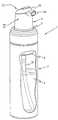
도 1은 본 발명에 따른 거품 분사 조립체의 부분 절단 사시도.1 is a partial cutaway perspective view of a foam jet assembly in accordance with the present invention;
도 2는 본 발명에 따른 거품 형성 유닛의 상세의 단면 사시도.2 is a sectional perspective view of the detail of the foam forming unit according to the present invention;
도 3은 도 2의 거품 형성 유닛의 부분 절단 상세도.3 is a partial cutaway detail of the foam forming unit of FIG. 2;
도 4는 제 2 실시예에 따른 거품 형성 유닛의 상세의 단면 사시도.4 is a sectional perspective view of a detail of the foam forming unit according to the second embodiment;
본 발명에 따른 거품 분사 조립체(1)는 그 내부에 거품을 위한 유체(3)를 가지며, 그 위에 거품 형성 유닛(4)이 배치된 원통형 유체 용기(2)를 포함한다(도 1). 거품 형성 유닛(4)은 각각 입구(inlet)와 출구(outlet)가 구비된 공기용 펌프(6)와 유체용 펌프(8)를 포함한다. 공기 펌프(6)의 입구(9)는 주위와 연통하는 반면(도 2), 유체 펌프(8)의 입구는 호스(10)를 통해 유체 용기(2)의 내용물(3)과 연통한다. 거품 형성 유닛(4)은 공기 펌프(6)의 출구(14)와 밸브(16)를 갖는 유체 펌프(8)의 출구와 연통하는 혼합 챔버(mixing chamber)(12)를 부가로 포함한다. 밸브(18)는 공기 펌프의 출구 근처에 부가로 배치된다.The
조립체의 상부는 거품 개구(26)(도2)를 갖는 유출 채널(outflow channel)(24)을 구비하는 분사부(dispensing part)(22)를 포함한다. 유출 채널(24)은 혼합 챔버(12)에서 거품 개구(26)까지 이어진다. 이러한 채널(24)에는 도 2에 도시한 실시예에서, 비교적 미세한 메시 스크린(34, 28)의 형태의 거품 형성 요소들이 배치되어 있다.The top of the assembly includes a dispensing
제 1 스크린(28)은 거품이 스크린(28)을 두 번 통과하도록 초음파 용접(ultrasonic welding)에 의해 배치된다. 이러한 목적을 위해 스크린(28) 위에는 스크린(28) 위에 캐비티(cavity)(32)를 형성하는 캡(30)이 배치되어 있다. 유동 방향에서 보이는 바와 같이, 캐비티(32)는 분출 요소(spout element)(51) 앞에 배치되어 있다. 캡(30)의 상부 벽은 간단하고 인간공학적(ergonomic) 작동의 목적으로 만곡되어 있다. 최소 높이 즉, 캡(30)과 스크린(28) 사이의 거리는 약 2 mm이며, 이 테스트들은 더 미세하고 더 균일한 거품을 위해 양호한 높이가 되는 것을 나타낸다. 스크린(28)은 10 ㎛ 와 150 ㎛ 사이, 적합하게는 50 ㎛ 정도의 치수의 개구를 가진다. 캡(30)은 그 색깔과 재료에서 변화 가능한 거품 형성 유닛의 독립된 부품(component)이다.The
도시된 적합한 실시예에서, 제 2 스크린(34)은 제 1 스크린 앞의 유출 채널에 부가로 배치되며, 0.1 mm 와 0.4 mm 사이, 적합하게는 0.2 mm 정도의 치수의 개구를 가진다. 제 2 스크린(34)은 사출 성형(injection molding)에 의해 배치되고, 구조 부품(61)의 일부를 형성하는 링(35)과 일체식으로 형성된다. 따라서, 거품 형성 유닛의 두 부품은 일체형이며, 그에 의해 원가와 조립 시간을 감소시킨다.In the suitable embodiment shown, the
유체와 공기의 혼합물은 제 2 스크린(34)을 거쳐서 혼합 챔버(12)를 떠나고, 거기에서 거품은 비교적 거친 구조로 형성된다. 그 다음, 거친 거품은 제 1 스크린(28)을 통과하여 캐비티(32)로 들어가고, 거기에서 거품의 구조는 더 미세하고 더 균일하게 즉, 거품내의 기포들이 더 작고 더 균일한 사이즈로 된다. 그 다음, 거품은 스크린(28)을 다시 통과하여 분출 개구(26)에 접근하고, 거기에서 거품은 더욱 더 미세하고 더 균일하게 된다.The mixture of fluid and air
거품의 품질(quality)은 두 개의 스크린을 종종 포함하는 공지된 거품 형성 유닛에서 보다 더 높다. 또한, 제조 비용을 공지된 거품 형성 유닛과 여전히 동일 하도록 제 1 스크린을 배치하기 위해서 하나의 제조 단계만이 필요하다. 거품 품질의 부가적인 개선을 위해서는, 제 3 스크린(도시 생략)이 에지(36)에 배치될 수 있다.The quality of the foam is higher than in known foaming units, which often include two screens. In addition, only one manufacturing step is necessary to arrange the first screen so that the manufacturing cost is still the same as known foam forming units. For further improvement of the foam quality, a third screen (not shown) may be disposed at the
다른 적합한 실시예에서, 공기 펌프의 공기 입구는 캡(30)과 벽(38) 사이에 배치된 갭(gap)(37)에 의해 형성된다(도 3). 공기는 유입되어 스페이스(40)로 진입하여 굴뚝으로서 작용하는 튜브(42)로 진출하고, 이러한 공기는 공기 펌프에 의해 공기 챔버(44)를 통과한다. 튜브(42)의 상부 단부(46)는 적합하게 경사져있고, 튜브의 길이 방향 축에 대한 각은 약 30˚이다. 튜브(42)는 스페이스(40) 안으로 약 4 mm의 예정된 길이로 돌출되어 있다. 따라서 이러한 구조는 밀폐된 굴뚝으로서 작용한다. 이러한 공기 입구는 거품 형성 유닛이 샤워 중에도 기능을 유지하도록 습한 환경에서 어떤 공기도 거의 유입되지 않는 장점을 갖는다.In another suitable embodiment, the air inlet of the air pump is formed by a
도 4는 본 발명에 따른 거품 형성 유닛의 제 2 실시예를 도시한다. 이 실시예는 도 2에 도시한 제 1 실시예와 대부분 동일하나, 혼합 요소(50)의 형태에서 다른 거품 형성 요소가 유출 채널(24)에 배치된 차이점을 가진다. 혼합 요소(50)는 제 1 거품 형성 요소(28)와 제 2 거품 형성 요소(34a) 사이에 배치된다. 혼합 요소(50)는 구조 부품(60)과 함께 성형되고(co-moulded), 약 1.5 mm의 단면을 갖는 네 개의 원형 홀들이 제공된 판형(plate-like) 요소로 구성된다. 혼합 요소(50)에서 개구들의 패턴과 치수들은 펌핑용 제품에 따라 변경될 수 있다. 다른 제 2 거품 형성 요소(34b)가 부가로 제공된다(이 요소의 위치는 도 4에 도시되어 있다).4 shows a second embodiment of the foam forming unit according to the invention. This embodiment is largely the same as the first embodiment shown in FIG. 2, with the difference that other foaming elements are arranged in the
제 2 거품 형성 요소(34a)는 구조 부품(61)과 함께 적합하게 성형되는 것에 주의해야 한다. 다른 제 2 거품 형성 요소(34b)는 구조 부품(61)의 상부 측면에 적합하게 용접된다. 제 1 거품 형성 요소(28)는 구조 부품(60)의 상부 에지(36)에 또한 적합하게 용접된다. 거품 형성 유닛은 실질적으로 세 개의 구조 부품(60, 61, 및 32)만으로 구성된다.It should be noted that the second
상술한 거품 형성 유닛(4)과 조립체(1)의 부가적인 작동은 본 출원인의 국제 특허 출원 0 242 005호에 기술되어 있다. 그 내용은 본 명세서에 합체되었다.Further operation of the
시스템은 다양한 배열을 가지며, 다수의 옵션들이 특정 유체에 거품 형성 유닛을 적용시키기 위해 이용될 수 있다. 매우 다양한 유체들(점성(viscosity), 틱소트로픽 작용(tixotropic behaviour), 화학 조성(chemical composition), 입자의 존재(the presence of particles) 등)이 존재하기 때문에, 구조가 펌핑용 유체에서 비교적 쉽게 변경될 수 있는 시스템 배열이다. 변수들(variables)은 거품 형성 요소에서 또는 각각에서 개구들의 수, 패턴, 및 사이즈인 다른 것들 중에서, 거품 형성 요소들의 수, 거품 형성 요소들(스크린이나 혼합 요소), 캐비티(32)의 치수들 등이다.The system has a variety of arrangements, and a number of options can be used to apply the foaming unit to a particular fluid. Due to the large variety of fluids (viscosity, tixotropic behaviour, chemical composition, the presence of particles, etc.), the structure changes relatively easily in the pumping fluid This can be a system array. The variables are the number of foam forming elements, foam forming elements (screen or mixing element), dimensions of the
본 발명은 상술한 적합한 실시예에 제한되지 않으며, 많은 변경을 예상할 수 있으나, 첨부한 청구범위의 범주에 의해 한정된다.The present invention is not limited to the above-described suitable embodiments, and many changes can be envisioned, but are limited by the scope of the appended claims.
Claims (17)
Translated fromKoreanApplications Claiming Priority (2)
| Application Number | Priority Date | Filing Date | Title |
|---|---|---|---|
| NL1022633 | 2003-02-10 | ||
| NL1022633ANL1022633C2 (en) | 2003-02-10 | 2003-02-10 | Improved foaming unit. |
Publications (2)
| Publication Number | Publication Date |
|---|---|
| KR20050103289A KR20050103289A (en) | 2005-10-28 |
| KR101082771B1true KR101082771B1 (en) | 2011-11-11 |
Family
ID=32844976
Family Applications (1)
| Application Number | Title | Priority Date | Filing Date |
|---|---|---|---|
| KR1020057014698AExpired - Fee RelatedKR101082771B1 (en) | 2003-02-10 | 2004-02-10 | Improved foam forming unit |
Country Status (15)
| Country | Link |
|---|---|
| US (1) | US7673854B2 (en) |
| EP (1) | EP1592515B1 (en) |
| JP (1) | JP2007528780A (en) |
| KR (1) | KR101082771B1 (en) |
| CN (1) | CN1756602B (en) |
| AT (1) | ATE394171T1 (en) |
| AU (1) | AU2004210295B2 (en) |
| BR (1) | BRPI0407003B1 (en) |
| CA (1) | CA2515794C (en) |
| DE (1) | DE602004013541D1 (en) |
| ES (1) | ES2305725T3 (en) |
| MX (1) | MXPA05008434A (en) |
| NL (1) | NL1022633C2 (en) |
| RU (1) | RU2304475C2 (en) |
| WO (1) | WO2004069418A1 (en) |
Families Citing this family (22)
| Publication number | Priority date | Publication date | Assignee | Title |
|---|---|---|---|---|
| NL1028827C2 (en) | 2005-04-20 | 2006-10-23 | Keltec B V | Delivery unit. |
| NL1030030C2 (en) | 2005-04-20 | 2006-10-23 | Keltec B V | Dispensing unit with improved supply shut-off means. |
| NL1030361C2 (en)* | 2005-11-07 | 2007-05-08 | Keltec B V | Dispensing unit with improved air supply. |
| NL1033031C2 (en)* | 2006-12-11 | 2008-06-12 | Rexam Airspray Nv | Foam form assembly, squeeze foamer and dispenser. |
| US8104650B2 (en)* | 2008-06-06 | 2012-01-31 | Pibed Ltd. | Anti drip device for liquid dispensers |
| JP4864052B2 (en)* | 2008-07-31 | 2012-01-25 | アース製薬株式会社 | Foam discharge pump product for washing nozzle washing of warm water washing toilet seat |
| US8348105B2 (en)* | 2008-09-03 | 2013-01-08 | Raymond Industrial Limited | Compact automatic homogenized liquid detergent dispensing device |
| JP5435794B2 (en)* | 2010-01-22 | 2014-03-05 | 大和製罐株式会社 | Pump type foam discharge container |
| WO2011112875A2 (en) | 2010-03-10 | 2011-09-15 | Nuvo Research Inc. | Foamable formulation |
| US8882086B2 (en) | 2011-09-13 | 2014-11-11 | Murillo Caporal Piotrovski | Rechargeable and resterilizable mixing device with physiological gas and solution to create foam with microbubbles, used in endovascular treatments |
| GB2507029B (en)* | 2012-07-11 | 2019-04-17 | Quantex Patents Ltd | Pump fittings and methods for their manufacture |
| WO2015162499A2 (en) | 2014-03-31 | 2015-10-29 | Piotrovski Murillo Caporal | Rechargeable and resterilizable mixing device with physiological gas and solution to create foam with microbubbles, used in endovascular treatments |
| EP3322539A1 (en) | 2015-07-15 | 2018-05-23 | Gary Rayner | Systems and methods for producing a foamable and/or flowable material for consumption |
| USD902738S1 (en)* | 2015-12-04 | 2020-11-24 | Gensco Laboratories Llc | Tamper proof safety container |
| CN105536191B (en)* | 2015-12-29 | 2018-12-04 | 中国石油化工股份有限公司 | Positive/negative-pressure couples apparatus for spray of foam |
| JP6582027B2 (en) | 2016-09-29 | 2019-09-25 | 花王株式会社 | Foam discharge container |
| CN107187724B (en)* | 2017-05-19 | 2019-08-23 | 钟竞铮 | Foam pump spray-head |
| US10779690B2 (en)* | 2017-12-27 | 2020-09-22 | Kao Corporation | Foaming dispenser |
| CN114206486A (en)* | 2019-08-08 | 2022-03-18 | 花王株式会社 | Foam dispenser, foam dispenser assembly and method of forming foam |
| USD980069S1 (en) | 2020-07-14 | 2023-03-07 | Ball Corporation | Metallic dispensing lid |
| WO2022187190A1 (en) | 2021-03-01 | 2022-09-09 | Ball Corporation | Metal container and end closure with seal |
| IL313184A (en) | 2021-11-29 | 2024-07-01 | Ironwood Pharmaceuticals Inc | Pharmaceutical compositions for the treatment of visceral pain |
Family Cites Families (12)
| Publication number | Priority date | Publication date | Assignee | Title |
|---|---|---|---|---|
| FR1398855A (en)* | 1964-03-19 | 1965-05-14 | Vaporisateurs Marcel Franck | Improvements to vaporizers with an alternative pump |
| US3447754A (en)* | 1964-10-16 | 1969-06-03 | Lewo Chem Fab Gmbh Fa | Foam cleaning |
| US3388868A (en)* | 1965-10-29 | 1968-06-18 | Nalco Chemical Co | Foam producing nozzle |
| US3428985A (en)* | 1967-02-28 | 1969-02-25 | Certified Chem & Equipment Co | Foam generator for rug cleaning machine |
| US4603812A (en)* | 1978-06-27 | 1986-08-05 | The Dow Chemical Company | Foam-generating pump sprayer |
| GB2189085B (en) | 1986-04-10 | 1989-11-22 | Plessey Co Plc | Electronics module mounting assembly |
| US5015370A (en)* | 1989-06-08 | 1991-05-14 | Anthony Fricano | Apparatus and method for treating well water |
| US5219102A (en)* | 1990-04-05 | 1993-06-15 | Earl Wright Company | Foaming device |
| JPH0669161U (en)* | 1993-03-05 | 1994-09-27 | 大和製罐株式会社 | Pump type foam container |
| US5462208A (en)* | 1994-08-01 | 1995-10-31 | The Procter & Gamble Company | Two-phase dispensing systems utilizing bellows pumps |
| US6612468B2 (en)* | 2000-09-15 | 2003-09-02 | Rieke Corporation | Dispenser pumps |
| ES2182815T3 (en)* | 2001-07-17 | 2003-03-16 | Guala Dispensing Spa | FOAM TRAINING DEVICE |
- 2003
- 2003-02-10NLNL1022633Apatent/NL1022633C2/ennot_activeIP Right Cessation
- 2004
- 2004-02-10CNCN2004800061279Apatent/CN1756602B/ennot_activeExpired - Lifetime
- 2004-02-10EPEP04709784Apatent/EP1592515B1/ennot_activeExpired - Lifetime
- 2004-02-10AUAU2004210295Apatent/AU2004210295B2/ennot_activeCeased
- 2004-02-10BRBRPI0407003-8Apatent/BRPI0407003B1/ennot_activeIP Right Cessation
- 2004-02-10USUS10/545,087patent/US7673854B2/enactiveActive
- 2004-02-10KRKR1020057014698Apatent/KR101082771B1/ennot_activeExpired - Fee Related
- 2004-02-10CACA2515794Apatent/CA2515794C/ennot_activeExpired - Fee Related
- 2004-02-10ATAT04709784Tpatent/ATE394171T1/ennot_activeIP Right Cessation
- 2004-02-10DEDE602004013541Tpatent/DE602004013541D1/ennot_activeExpired - Fee Related
- 2004-02-10ESES04709784Tpatent/ES2305725T3/ennot_activeExpired - Lifetime
- 2004-02-10MXMXPA05008434Apatent/MXPA05008434A/enactiveIP Right Grant
- 2004-02-10WOPCT/NL2004/000096patent/WO2004069418A1/enactiveSearch and Examination
- 2004-02-10JPJP2006502742Apatent/JP2007528780A/enactivePending
- 2004-02-10RURU2005128306/12Apatent/RU2304475C2/enactive
Also Published As
| Publication number | Publication date |
|---|---|
| JP2007528780A (en) | 2007-10-18 |
| CA2515794C (en) | 2010-01-26 |
| US7673854B2 (en) | 2010-03-09 |
| AU2004210295A1 (en) | 2004-08-19 |
| MXPA05008434A (en) | 2005-11-17 |
| BRPI0407003B1 (en) | 2015-06-16 |
| DE602004013541D1 (en) | 2008-06-19 |
| RU2304475C2 (en) | 2007-08-20 |
| CA2515794A1 (en) | 2004-08-19 |
| EP1592515A1 (en) | 2005-11-09 |
| NL1022633C2 (en) | 2004-08-12 |
| AU2004210295B2 (en) | 2009-09-10 |
| CN1756602A (en) | 2006-04-05 |
| CN1756602B (en) | 2010-08-04 |
| EP1592515B1 (en) | 2008-05-07 |
| BRPI0407003A (en) | 2006-01-10 |
| US20070023933A1 (en) | 2007-02-01 |
| ATE394171T1 (en) | 2008-05-15 |
| KR20050103289A (en) | 2005-10-28 |
| RU2005128306A (en) | 2006-04-10 |
| ES2305725T3 (en) | 2008-11-01 |
| WO2004069418A1 (en) | 2004-08-19 |
Similar Documents
| Publication | Publication Date | Title |
|---|---|---|
| KR101082771B1 (en) | Improved foam forming unit | |
| CN100444968C (en) | foam generator | |
| JP3422329B2 (en) | Discharge device | |
| KR101826634B1 (en) | Mist pump of cosmetic containers | |
| KR950700127A (en) | CONSUMER PRODUCT PACKAGE INCORPORATIMG A SPRAY DEVICE UTILIZING LARGE DIAMETER BUBBLES | |
| AU2002238562A1 (en) | Foamer | |
| CN112088048B (en) | Spray container | |
| CN1902007B (en) | Distributors for concentrated spraying | |
| JP2007516060A (en) | Nozzle arrangement | |
| JPH11276944A (en) | Spraying vessel | |
| WO2009130462A9 (en) | Manual pump type fluid dispenser | |
| JP3329809B2 (en) | Media ejection head | |
| KR900004592B1 (en) | Air induction sprayer | |
| KR920003862B1 (en) | Foam producing method and dispenser | |
| EP1644125A1 (en) | Nozzle arrangements | |
| JP4373398B2 (en) | Injection disperser | |
| CN114206486A (en) | Foam dispenser, foam dispenser assembly and method of forming foam | |
| EA035904B1 (en) | Foam dispenser | |
| JP2005313110A (en) | Bubble formation device and pump type bubbling out vessel | |
| JP2006272304A (en) | Spherical or elliptical dual structured pressurizing/atomizing nozzle |
Legal Events
| Date | Code | Title | Description |
|---|---|---|---|
| PA0105 | International application | St.27 status event code:A-0-1-A10-A15-nap-PA0105 | |
| P11-X000 | Amendment of application requested | St.27 status event code:A-2-2-P10-P11-nap-X000 | |
| P13-X000 | Application amended | St.27 status event code:A-2-2-P10-P13-nap-X000 | |
| PG1501 | Laying open of application | St.27 status event code:A-1-1-Q10-Q12-nap-PG1501 | |
| R17-X000 | Change to representative recorded | St.27 status event code:A-3-3-R10-R17-oth-X000 | |
| A201 | Request for examination | ||
| PA0201 | Request for examination | St.27 status event code:A-1-2-D10-D11-exm-PA0201 | |
| P11-X000 | Amendment of application requested | St.27 status event code:A-2-2-P10-P11-nap-X000 | |
| P13-X000 | Application amended | St.27 status event code:A-2-2-P10-P13-nap-X000 | |
| E902 | Notification of reason for refusal | ||
| PE0902 | Notice of grounds for rejection | St.27 status event code:A-1-2-D10-D21-exm-PE0902 | |
| R17-X000 | Change to representative recorded | St.27 status event code:A-3-3-R10-R17-oth-X000 | |
| T11-X000 | Administrative time limit extension requested | St.27 status event code:U-3-3-T10-T11-oth-X000 | |
| E13-X000 | Pre-grant limitation requested | St.27 status event code:A-2-3-E10-E13-lim-X000 | |
| P11-X000 | Amendment of application requested | St.27 status event code:A-2-2-P10-P11-nap-X000 | |
| P13-X000 | Application amended | St.27 status event code:A-2-2-P10-P13-nap-X000 | |
| E701 | Decision to grant or registration of patent right | ||
| PE0701 | Decision of registration | St.27 status event code:A-1-2-D10-D22-exm-PE0701 | |
| GRNT | Written decision to grant | ||
| PR0701 | Registration of establishment | St.27 status event code:A-2-4-F10-F11-exm-PR0701 | |
| PR1002 | Payment of registration fee | St.27 status event code:A-2-2-U10-U12-oth-PR1002 Fee payment year number:1 | |
| PG1601 | Publication of registration | St.27 status event code:A-4-4-Q10-Q13-nap-PG1601 | |
| LAPS | Lapse due to unpaid annual fee | ||
| PC1903 | Unpaid annual fee | St.27 status event code:A-4-4-U10-U13-oth-PC1903 Not in force date:20141108 Payment event data comment text:Termination Category : DEFAULT_OF_REGISTRATION_FEE | |
| PC1903 | Unpaid annual fee | St.27 status event code:N-4-6-H10-H13-oth-PC1903 Ip right cessation event data comment text:Termination Category : DEFAULT_OF_REGISTRATION_FEE Not in force date:20141108 | |
| P22-X000 | Classification modified | St.27 status event code:A-4-4-P10-P22-nap-X000 |