KR101079994B1 - Resource requests for a wireless communication system - Google Patents
Resource requests for a wireless communication systemDownload PDFInfo
- Publication number
- KR101079994B1 KR101079994B1KR1020097018136AKR20097018136AKR101079994B1KR 101079994 B1KR101079994 B1KR 101079994B1KR 1020097018136 AKR1020097018136 AKR 1020097018136AKR 20097018136 AKR20097018136 AKR 20097018136AKR 101079994 B1KR101079994 B1KR 101079994B1
- Authority
- KR
- South Korea
- Prior art keywords
- information
- resource request
- wireless communication
- qos
- backlog level
- Prior art date
- Legal status (The legal status is an assumption and is not a legal conclusion. Google has not performed a legal analysis and makes no representation as to the accuracy of the status listed.)
- Active
Links
Images


Classifications
- H—ELECTRICITY
- H04—ELECTRIC COMMUNICATION TECHNIQUE
- H04W—WIRELESS COMMUNICATION NETWORKS
- H04W28/00—Network traffic management; Network resource management
- H04W28/16—Central resource management; Negotiation of resources or communication parameters, e.g. negotiating bandwidth or QoS [Quality of Service]
- H04W28/24—Negotiating SLA [Service Level Agreement]; Negotiating QoS [Quality of Service]
- H—ELECTRICITY
- H04—ELECTRIC COMMUNICATION TECHNIQUE
- H04W—WIRELESS COMMUNICATION NETWORKS
- H04W72/00—Local resource management
- H04W72/20—Control channels or signalling for resource management
- H04W72/21—Control channels or signalling for resource management in the uplink direction of a wireless link, i.e. towards the network
- H—ELECTRICITY
- H04—ELECTRIC COMMUNICATION TECHNIQUE
- H04W—WIRELESS COMMUNICATION NETWORKS
- H04W74/00—Wireless channel access
- H04W74/08—Non-scheduled access, e.g. ALOHA
- H04W74/0866—Non-scheduled access, e.g. ALOHA using a dedicated channel for access
Landscapes
- Engineering & Computer Science (AREA)
- Quality & Reliability (AREA)
- Computer Networks & Wireless Communication (AREA)
- Signal Processing (AREA)
- Mobile Radio Communication Systems (AREA)
Abstract
Translated fromKoreanDescription
Translated fromKorean본 발명은 2007년 1월 30일자로 출원된, "A METHOD AND APPARATUS FOR USING A REVERSE CONTROL CHANNEL MAC PROTOCOL"라는 제목의 미국 가출원 번호 제60/887,342호 및 2007년 2월 5일자로 출원된 "RESOURCE REQUESTS FOR WIRELESS COMMUNICATION SYSTEMS"라는 제목의 미국 가출원 번호 제60/888,192호에 대한 우선권을 주장한다.The present invention discloses US Provisional Application No. 60 / 887,342, entitled "A METHOD AND APPARATUS FOR USING A REVERSE CONTROL CHANNEL MAC PROTOCOL," filed January 30, 2007, and "RESOURCE, filed February 5, 2007." Priority to US Provisional Application No. 60 / 888,192 entitled "REQUESTS FOR WIRELESS COMMUNICATION SYSTEMS".
본 출원은 일반적으로 통신에 관한 것으로서, 특히, 무선 통신 시스템에서 무선 리소스들을 요청하기 위한 기술들에 관한 것이다.TECHNICAL FIELD This application relates generally to communications, and more particularly, to techniques for requesting radio resources in a wireless communication system.
무선 통신 시스템들은 음성, 비디오, 패킷 데이터, 메시징, 브로드캐스트 등과 같은 다양한 통신 컨텐츠를 제공하기 위하여 광범위하게 이용된다. 이러한 무선 시스템들은 이용가능한 시스템 리소스들을 공유함으로써 다수의 사용자들을 지원할 수 있는 다중-액세스 시스템들일 수 있다. 그러한 다중-액세스 시스템들의 실시예들은 코드 분할 다중 액세스(CDMA) 시스템들, 시분할 다중 액세스(TDMA) 시스템들, 주파수 분할 다중 액세스(FDMA) 시스템들, 직교 FDMA(OFDMA) 시스템들, 및 단일-캐리어 FDMA(SC-FDMA) 시스템들을 포함한다.Wireless communication systems are widely used to provide various communication content such as voice, video, packet data, messaging, broadcast, and the like. Such wireless systems may be multiple-access systems capable of supporting multiple users by sharing the available system resources. Embodiments of such multiple-access systems include code division multiple access (CDMA) systems, time division multiple access (TDMA) systems, frequency division multiple access (FDMA) systems, orthogonal FDMA (OFDMA) systems, and single-carrier. Including FDMA (SC-FDMA) systems.
무선 통신 시스템은 순방향 및 역방향 링크들상에서 다수의 단말들에 대한 통신을 지원할 수 있는 다수의 기지국들을 포함할 수 있다. 순방향 링크(또는 다운링크)는 기지국들로부터 모바일 디바이스들로의 통신 링크를 지칭하고, 역방향 링크(또는 업링크)는 모바일 디바이스들로부터 기지국들로의 통신 링크를 지칭한다. 시스템은 단말이 역방향 링크상에서 송신하기 위한 데이터를 가질 때마다, 무선 리소스들에 대한 요청을 송신할 수 있는 리소스 할당 방식을 이용할 수 있다. 일반적으로, 무선 리소스들은 시간, 주파수, 코드, 전력 및/또는 송신을 위해 사용가능한 다른 타입의 리소스들을 포함할 수 있다. 기지국은 단말로부터의 리소스 요청을 프로세싱할 수 있으며, 단말로 무선 리소스들의 허가(grant)를 송신할 수 있다. 그 후, 단말은 허가된 리소스들을 사용하여 역방향 링크상에서 데이터를 송신할 수 있다. 역방향 링크 리소스들은 리소스 요청들을 송신하기 위하여 소모된다. 따라서, 리소스 요청들을 효율적으로 송신하기 위한 기술들에 대한 요구가 본 기술분야에 존재한다.The wireless communication system may include a number of base stations capable of supporting communication for a number of terminals on forward and reverse links. The forward link (or downlink) refers to the communication link from the base stations to the mobile devices, and the reverse link (or uplink) refers to the communication link from the mobile devices to the base stations. The system can use a resource allocation scheme that can send a request for radio resources whenever the terminal has data for transmission on the reverse link. In general, wireless resources may include time, frequency, code, power, and / or other types of resources available for transmission. The base station may process a resource request from the terminal and may transmit a grant of radio resources to the terminal. The terminal can then transmit data on the reverse link using the authorized resources. Reverse link resources are consumed to send resource requests. Thus, a need exists in the art for techniques for efficiently sending resource requests.
무선 통신 시스템에서 리소스 요청들을 송신하기 위한 기술들이 본 명세서에 개시된다. 일 양상에서, 다수의 타입의 서비스 품질(QoS) 정보가 리소스 요청들에 대하여 지원될 수 있으며, QoS 클래스 및 레이턴시(latency) 기한(deadline)을 포함할 수 있다. 단말은 역방향 링크상에서 송신하기 위한 데이터를 가질 수 있으며, 데이터에 대한 QoS 정보를 결정할 수 있다. QoS 정보는 적어도 하나의 QoS 타입을 포함할 수 있으며, 이는 리소스 요청들을 송신하기 위해 사용하기 위하여 선택되는 구성에 좌우될 수 있다. 단말은 또한 송신하기 위한 데이터량을 나타내는 백로그(backlog) 레벨 정보를 결정할 수 있다. 단말은 백로그 레벨 정보 및 QoS 정보를 포함하는 리소스 요청을 생성하여 송신할 수 있다. 일 설계에서, 리소스 요청은 (ⅰ) 제1 구성에 대한 QoS 클래스 정보 및 백로그 레벨 정보, (ⅱ) 제2 구성에 대한 QoS 클래스 정보 또는 레이턴시 기한 정보 중 하나 및 백로그 레벨 정보, (ⅲ) 제3 구성에 대한 레이턴시 기한 정보 및 백로그 레벨 정보를 포함할 수 있다. 리소스 요청은 또한 다른 설계들에 대한 정보의 몇몇 다른 결합을 포함할 수 있다.Techniques for transmitting resource requests in a wireless communication system are disclosed herein. In one aspect, multiple types of quality of service (QoS) information may be supported for resource requests, and may include a QoS class and latency deadline. The terminal may have data for transmission on the reverse link and may determine QoS information for the data. The QoS information may include at least one QoS type, which may depend on the configuration selected for use to send resource requests. The terminal may also determine backlog level information indicating the amount of data to transmit. The terminal may generate and transmit a resource request including backlog level information and QoS information. In one design, the resource request includes (i) one of the QoS class information and backlog level information for the first configuration, (ii) one of the QoS class information or latency due date information for the second configuration and (i) Latency due date information and backlog level information for the third configuration may be included. The resource request may also include some other combination of information for other designs.
다른 양상에서, 다수의 포맷들이 리소스 요청들에 대하여 지원될 수 있다. 단말은 리소스 요청에서 송신하기 위한 적어도 하나의 타입의 정보를 결정할 수 있다. 단말은 송신하기 위한 적어도 하나의 타입의 정보에 기초하여 다수의 포맷들 중에서 리소스 요청에 대하여 사용하기 위한 포맷을 결정할 수 있다. 다수의 포맷들은 백로그 레벨 및 QoS 정보에 대한 제1 포맷 및 단지 백로그 레벨에 대한 제2 포맷을 포함할 수 있다. 단말은 결정된 포맷으로 적어도 하나의 타입의 정보를 포함하는 리소스 요청을 생성할 수 있다. 일 설계에서, 리소스 요청은 모든 포맷들에 대하여 일정한 개수의 비트들(예를 들어, 6개의 비트들)을 가질 수 있고, 제1 포맷은 제1 범위의 값들(예를 들어, 0 내지 47)에 대응할 수 있으며, 제2 포맷은 제2 범위의 값들(예를 들어, 48 내지 63)에 대응할 수 있다.In another aspect, multiple formats may be supported for resource requests. The terminal may determine at least one type of information for transmitting in the resource request. The terminal may determine a format to use for a resource request among a plurality of formats based on at least one type of information for transmission. Multiple formats may include a first format for the backlog level and QoS information and a second format for the backlog level only. The terminal may generate a resource request including at least one type of information in the determined format. In one design, the resource request may have a certain number of bits (eg, six bits) for all formats, and the first format may have a first range of values (eg, 0 to 47). The second format may correspond to values of the second range (eg, 48 to 63).
하기에서 본 발명의 다양한 양상들 및 특징들이 보다 상세히 설명된다.In the following various aspects and features of the invention are described in more detail.
도 1은 무선 통신 시스템을 도시한다.1 illustrates a wireless communication system.
도 2는 수퍼프레임(superframe) 구조의 설계를 도시한다.2 shows a design of a superframe structure.
도 3은 리소스 요청의 설계를 도시한다.3 shows a design of a resource request.
도 4는 리소스 요청의 다른 도면을 도시한다.4 shows another diagram of a resource request.
도 5 및 6은 각각 QoS 정보를 갖는 리소스 요청들을 송신하기 위한 프로세스 및 장치를 도시한다.5 and 6 illustrate a process and apparatus for transmitting resource requests with QoS information, respectively.
도 7 및 8은 각각 상이한 포맷들로 리소스 요청들을 송신하기 위한 프로세스 및 장치를 도시한다.7 and 8 illustrate a process and apparatus for transmitting resource requests in different formats, respectively.
도 9 및 10은 각각 QoS 정보를 갖는 리소스 요청들을 송신하기 위한 다른 프로세스 및 다른 장치를 도시한다.9 and 10 show another process and another apparatus for transmitting resource requests with QoS information, respectively.
도 11 및 12는 각각 스펙트럼 효율을 고려함으로써 리소스 요청들을 송신하기 위한 프로세스 및 장치를 도시한다.11 and 12 illustrate a process and apparatus for transmitting resource requests by considering spectral efficiency, respectively.
도 13 및 14는 각각 백오프를 갖는 제어 메시지들을 송신하기 위한 프로세스 및 장치를 도시한다.13 and 14 illustrate a process and apparatus for transmitting control messages with backoff, respectively.
도 15는 기지국 및 단말의 블럭도를 도시한다.15 shows a block diagram of a base station and a terminal.
도 1은 액세스 네트워크(AN)로서 또한 지칭될 수 있는 무선 통신 시스템(100)을 보여준다. 시스템(100)은 다수의 기지국(110)을 포함할 수 있다. 기지국은 단말들과 통신하는 스테이션이며, 액세스 포인트, 노드 B, 진화된 노드 B 등으로서 또한 지칭될 수 있다. 각각의 기지국은 특정 지리학적 영역에 대한 통신 커버리지를 제공한다. 시스템 제어기(130)는 기지국들(110)에 연결되고, 이러한 기지국들에 대한 조정 및 제어를 제공할 수 있다.1 shows a
단말들(120)은 시스템 전반을 통해 분산될 수 있으며, 각각의 단말은 고정되거나 또는 이동성일 수 있다. 단말은 또한 액세스 단말(AT), 이동국, 사용자 장비, 가입자국, 스테이션 등으로 지칭될 수 있다. 단말은 셀룰러 전화, 개인용 디지털 단말(PDA), 무선 통신 디바이스, 무선 모뎀, 핸드헬드(handheld) 디바이스, 랩탑 컴퓨터, 코드리스(cordless) 전화 등일 수 있다. 단말은 임의의 주어진 순간에 순방향 및/또는 역방향 링크들상의 0개, 1개, 또는 다수의 기지국들과 통신할 수 있다.
본 명세서에 개시되는 기술들은 CDMA, TDMA, FDMA, OFDMA 및 SC-FDMA 시스템들과 같은 다양한 무선 통신 시스템들에 대하여 사용될 수 있다. "시스템" 및 "네트워크"라는 용어들은 종종 상호교환가능하게 사용된다. CDMA 시스템은 cdma2000, UTRA(Universal Terrestrial Radio Access), 등과 같은 무선 기술을 구현할 수 있다. OFDMA 시스템은 UMB(Ultra Mobile Broadband), E-UTRA(Evolved UTRA), IEEE 802.16(WiMAX), IEEE 802.20, Flash-OFDM®, 등과 같은 무선 기술을 구현할 수 있다. UTRA 및 E-UTRA는 "제3세대 파트너쉽 프로젝트"(3GPP)으로 명명된 기관으로부터의 문헌들에 개시된다. cdma2000 및 UMB는 "제3세대 파트너쉽 프로젝트 2"(3GPP2)로 명명된 기관으로부터의 문헌들에 개시된다. 이러한 다양한 무선 기술들 및 표준들이 본 기술분야에 공지된다.The techniques disclosed herein may be used for a variety of wireless communication systems, such as CDMA, TDMA, FDMA, OFDMA, and SC-FDMA systems. The terms "system" and "network" are often used interchangeably. CDMA systems may implement radio technologies such as cdma2000, Universal Terrestrial Radio Access (UTRA), and the like. An OFDMA system can implement radio technologies such as Ultra Mobile Broadband (UMB), Evolved UTRA (E-UTRA), IEEE 802.16 (WiMAX), IEEE 802.20, Flash-OFDM®, and the like. UTRA and E-UTRA are disclosed in documents from an organization named "3rd Generation Partnership Project" (3GPP). cdma2000 and UMB are disclosed in documents from an organization named "3rd Generation Partnership Project 2" (3GPP2). These various radio technologies and standards are known in the art.
명료성을 위하여, 기술들의 특정 양상들이 하기에서 UMB에 대하여 설명되고, UMB라는 용어는 하기의 대부분의 설명에서 사용된다. UMB는 직교 주파수 분할 멀티플렉싱(OFDM) 및 코드 분할 멀티플렉싱(CDM)의 결합을 이용한다. UMB는 "Physical Layer for Ultra Mobile Broadband (UMB) Air Interface Specification"라는 제목의 3GPP2 C.S0084-001, "Medium Access Control Layer For Ultra Mobile Broadband (UMB) Air Interface Specification"라는 제목의 C.S0084-002, 및 "Radio Link Layer for Ultra Mobile Broadband (UMB) Air Interface Specification"라는 제목의 C.S0084-003에 개시되며, 이들 모두는 2007년 8월자이며, 공개적으로 이용가능하다.For clarity, certain aspects of the techniques are described below for UMBs, and the term UMB is used in most of the description below. UMB uses a combination of orthogonal frequency division multiplexing (OFDM) and code division multiplexing (CDM). UMB is a 3GPP2 C.S0084-001 titled "Physical Layer for Ultra Mobile Broadband (UMB) Air Interface Specification" and a C.S0084-002 titled "Medium Access Control Layer For Ultra Mobile Broadband (UMB) Air Interface Specification" , And C.S0084-003 entitled "Radio Link Layer for Ultra Mobile Broadband (UMB) Air Interface Specification", all of which are dated August 2007 and are publicly available.
도 2는 역방향 링크에 대하여 사용될 수 있는 수퍼프레임 구조(200)의 설계를 보여준다. 송신 타임라인(timeline)은 수퍼프레임들의 유닛(unit)들로 분할될 수 있다. 각각의 수퍼프레임은 특정 시간 기간 범위에 걸쳐있을 수 있으며, 특정 시간 기간은 고정되거나 구성가능할 수 있다. 각각의 수퍼프레임은 M개의 물리 계층(PHY) 프레임들로 분할될 수 있으며, 여기서, 일반적으로 M > 1이다. 일 설계에서, M = 25이고, 각각의 수퍼프레임에 25개 PHY 프레임들에 0 내지 24의 인덱스들이 할당된다. 각각의 PHY 프레임은 N개의 OFDM 심볼 기간들을 커버할 수 있으며, 일반적으로 N > 1이고, 일 설계예에서는 N = 8이다.2 shows a design of a
도 2는 또한 서브캐리어 구조를 보여준다. 시스템 대역폭은 톤들, 빈들 등으로서 또한 지칭될 수 있는 다수의(K) 직교 서브캐리어들로 분할될 수 있다. 인접 서브캐리어들 사이에서의 간격(spacing)은 고정될 수 있으며, 서브캐리어들의 개수는 시스템 대역폭에 좌우될 수 있다. 예를 들어, 1.25, 2.5, 5, 10 또는 20 MHz의 시스템 대역폭에 대하여 각각 128개, 256개, 512개, 1024개 또는 2048개 서브캐리어들이 존재할 수 있다.2 also shows the subcarrier structure. The system bandwidth may be divided into a number of (K) orthogonal subcarriers, which may also be referred to as tones, bins, and the like. Spacing between adjacent subcarriers may be fixed, and the number of subcarriers may depend on the system bandwidth. For example, there may be 128, 256, 512, 1024 or 2048 subcarriers for a system bandwidth of 1.25, 2.5, 5, 10 or 20 MHz, respectively.
도 2는 또한 역방향 링크상의 파일럿, 시그널링, 및 몇몇 트래픽 데이터의 송신을 지원할 수 있는 CDMA 세그먼트의 설계를 도시한다. CDMA 세그먼트는 역방향 CDMA 전용 제어 채널(R-CDCCH)과 같은 하나 이상의 물리적 채널들을 지원할 수 있다. R-CDCCH는 역방향 링크 요청 채널(r-reqch)과 같은 하나 이상의 논리적 채널들을 포함(carry)할 수 있다. CDMA 세그먼트는 임의의 크기(dimension)일 수 있는 시간 주파수 리소스들의 블럭을 차지할 수 있다. 일 설계에서, CDMA 세그먼트는 C개의 CDMA 서브세그먼트들을 포함할 수 있으며, 여기서, 일반적으로 C ≥ 1이다. 각각의 CDMA 서브세그먼트는 하나의 PHY 프레임의 N개 OFDM 심볼 기간들에서 S개의 인접하는 서브캐리어들을 커버할 수 있으며, 일 설계예에서, S = 128이다.2 also shows a design of a CDMA segment that can support the pilot, signaling, and transmission of some traffic data on the reverse link. The CDMA segment may support one or more physical channels, such as a reverse CDMA dedicated control channel (R-CDCCH). The R-CDCCH may carry one or more logical channels, such as a reverse link request channel (r-reqch). The CDMA segment may occupy a block of time frequency resources that can be of any dimension. In one design, a CDMA segment may include C CDMA subsegments, where C> 1 in general. Each CDMA subsegment may cover S contiguous subcarriers in the N OFDM symbol periods of one PHY frame, in one design, S = 128.
도 2에 보여지는 설계에서, CDMA 세그먼트는 모든 Q PHY 프레임들마다 송신되고, 일반적으로, Q ≥ 1인데, 몇몇 실시예들로서, Q = 4 , 6, 8 등이다. CDMA 세그먼트는 시간에 따라 시스템 대역폭에 걸쳐 호핑(hop) 할 수 있거나(도 2에 도시되는 바와 같이), 또는 고정된 세트의 서브캐리어들상에서 송신될 수 있다(도 2에 미도시). 다수의 단말들은 파일럿, 시그널링 등에 대한 CDMA 세그먼트를 공유할 수 있다.In the design shown in FIG. 2, the CDMA segment is transmitted every Q PHY frames, and generally Q ≧ 1, in some embodiments Q = 4, 6, 8, and so on. The CDMA segment may hop over system bandwidth over time (as shown in FIG. 2) or may be transmitted on a fixed set of subcarriers (not shown in FIG. 2). Multiple terminals may share a CDMA segment for pilot, signaling, and the like.
단말에는 역방향 OFDMA 데이터 채널(R-ODCH)에 대한 역방향 링크 리소스들이 할당될 수 있다. 일 설계에서, 할당된 리소스들은 타일들의 유닛들에 주어질 수 있다. 타일은 시간 주파수 리소스들의 블럭일 수 있으며, 미리 결정된 개수의 심 볼 기간들에서 미리 결정된 개수의 서브캐리어들을 커버할 수 있다. 일 설계에서, 타일은 하나의 PHY 프레임의 8개 심볼 기간들에서 16개의 서브캐리어들을 커버하고, 128개에 달하는 심볼들을 송신하는데 사용될 수 있다. 할당된 타일들은 도 2에 도시되는 바와 같이, 홉핑 패턴에 기초하여 시스템 대역폭에 걸쳐 호핑할 수 있다. 단말은 할당된 타일들상에 데이터 및/또는 인밴드(inband) 시그널링을 송신할 수 있다.The terminal may be allocated reverse link resources for the reverse OFDMA data channel (R-ODCH). In one design, allocated resources may be given to units of tiles. The tile may be a block of time frequency resources and may cover a predetermined number of subcarriers in a predetermined number of symbol periods. In one design, a tile may be used to cover 16 subcarriers in eight symbol periods of one PHY frame and transmit up to 128 symbols. The assigned tiles may hop across the system bandwidth based on the hopping pattern, as shown in FIG. The terminal may transmit data and / or inband signaling on the assigned tiles.
단말은 하나 이상의 플로우들을 구성하기 위하여 액세스 네트워크와 통신할 수 있다. 각각의 플로우는 하나 이상의 스트림들의 콜렉션일 수 있다. 각각의 스트림은 하나 이상의 더 높은 계층 애플리케이션들의 콜렉션일 수 있으며, 하나 이상의 애플리케이션들에 대한 데이터 및/또는 제어 정보를 운반할 수 있다. 각각의 애플리케이션은 예약과 연관될 수 있으며, 예약은 그러한 애플리케이션에 대한 패킷들을 식별하기 위한 패킷 필터들의 세트를 포함할 수 있다. 예를 들어, 하이퍼텍스트 송신 프로토콜(HTTP), 파일 송신 프로토콜(FTP), 음성, 및 비디오와 같은 상이한 애플리케이션들은 하나 이상의 플로우들상에서 운반되는 하나 이상의 스트림들에 맵핑될 수 있다. 각각의 애플리케이션은 특정 요건들을 가질 수 있다. 단말은 QoS 블로브(blob)들 또는 프로파일들을 사용하여 활성화된 애플리케이션들의 요건들을 보고할 수 있다. 액세스 네트워크는 상기 플로우에 맵핑되는 모든 애플리케이션들에 대한 보고된 QoS 블로브들 또는 프로파일들에 기초하여 각각의 플로우의 QoS 요건들을 결정할 수 있다. 각각의 플로우는 특정 QoS 클래스에 속할 수 있으며, 특정 QoS 클래스는 상기 플로우에 대한 QoS 요건들의 세트와 연관될 수 있 다. 상이한 QoS 클래스들은 QoS 요건들의 상이한 세트들과 연관될 수 있다.The terminal may communicate with the access network to configure one or more flows. Each flow may be a collection of one or more streams. Each stream may be a collection of one or more higher layer applications and may carry data and / or control information for one or more applications. Each application may be associated with a reservation, which may include a set of packet filters for identifying packets for that application. For example, different applications such as hypertext transfer protocol (HTTP), file transfer protocol (FTP), voice, and video may be mapped to one or more streams carried on one or more flows. Each application may have certain requirements. The terminal may report the requirements of the activated applications using QoS blobs or profiles. The access network may determine the QoS requirements of each flow based on reported QoS blobs or profiles for all applications mapped to the flow. Each flow may belong to a particular QoS class, and the particular QoS class may be associated with a set of QoS requirements for that flow. Different QoS classes may be associated with different sets of QoS requirements.
일 설계에서, 다수의 구성들이 플로우들에 대하여 지원될 수 있다. 제1 플로우 구성에서, 8개에 달하는 플로우들이 지원될 수 있으며, 각각의 플로우는 상이한 QoS 클래스와 연관될 수 있다. 제2 플로우 구성에서, 4개에 달하는 플로우들이 지원될 수 있으며, 각각의 플로우는 상이한 QoS 클래스와 연관될 수 있다. 적절한 플로우 구성은 단말에서 모든 활성화된 애플리케이션들에 대한 보고된 QoS 블로브들 또는 프로파일들에 기초하여 선택될 수 있다(예를 들어, 액세스 네트워크에 의하여).In one design, multiple configurations may be supported for the flows. In the first flow configuration, up to eight flows may be supported, and each flow may be associated with a different QoS class. In the second flow configuration, up to four flows may be supported, each flow associated with a different QoS class. The appropriate flow configuration may be selected based on reported QoS blobs or profiles for all activated applications at the terminal (eg, by the access network).
단말은 송신하기 위한 데이터가 존재할 때마다 R-ODCH상의 각각의 스트림에 대하여 데이터를 송신할 수 있다. R-ODCH는 기지국에 대한 스케줄러에 의하여 스케줄링될 수 있다. 단말은 임의의 스트림에 대하여 송신하기 위한 데이터가 존재할 때마다 요청 채널상에서 리소스 요청을 송신할 수 있다. 스케줄러는 리소스 요청에 응답하여 R-ODCH상의 리소스들을 단말에 할당할 수 있다. 리소스들의 효율적인 스케줄링 및 할당을 지원하기 위하여 리소스 요청이 단말에 의하여 송신될 데이터에 관한 적절한 정보를 제공하는 것이 바람직할 수 있다.The terminal may transmit data for each stream on the R-ODCH whenever there is data to transmit. The R-ODCH may be scheduled by the scheduler for the base station. The terminal may transmit a resource request on the request channel whenever there is data to transmit for any stream. The scheduler may allocate resources on the R-ODCH to the terminal in response to the resource request. In order to support efficient scheduling and allocation of resources, it may be desirable to provide appropriate information regarding the data to be transmitted by the terminal.
일 양상에서, 리소스 요청은 데이터에 대한 QoS 정보뿐 아니라, 송신하기 위한 데이터량을 나타내는 정보를 포함할 수 있다. 송신하기 위한 데이터량을 나타내는 정보는 백로그 레벨, 버퍼 크기, 큐 크기, 페이로드(payload) 크기 등으로서 또한 지칭될 수 있다. 명료성을 위하여, 백로그 레벨은 하기의 설명의 대부분에서 사용된다. QoS 정보는 하기에 설명되는 바와 같이, 다수의 방식들로 제공될 수 있 다. 백로그 레벨 정보 및 QoS 정보는 역방향 링크상에서 데이터 송신을 위해 어느 단말을 스케줄링할지 및/또는 각각의 스케줄링된 단말에 할당하기 위하여 얼마나 많은 리소스들을 할당할지를 결정하기 위하여 스케줄러에 의하여 사용될 수 있다.In an aspect, the resource request may include information indicating the amount of data to transmit, as well as QoS information for the data. Information indicative of the amount of data to transmit may also be referred to as backlog level, buffer size, queue size, payload size, and the like. For clarity, backlog levels are used in much of the description below. QoS information may be provided in a number of ways, as described below. The backlog level information and QoS information may be used by the scheduler to determine which terminal to schedule for data transmission on the reverse link and / or how many resources to allocate to each scheduled terminal.
리소스 요청은 일정한(fixed) 크기를 가질 수 있으며, 고정된 개수의 비트들과 함께 송신될 수 있다. 송신하기 위한 데이터에 대하여 가능한 많은 정보를 운반하기 위하여 이용가능한 비트들을 이용하는 것이 바람직하다. 일반적으로, 임의의 개수의 비트들이 리소스 요청에 대하여 사용될 수 있다. 명료성을 위하여, 하기의 설명의 대부분이 리소스 요청이 6개의 비트들과 함께 송신되는 설계에 대한 것이다.The resource request may have a fixed size and may be sent with a fixed number of bits. It is desirable to use the available bits to carry as much information as possible about the data to transmit. In general, any number of bits can be used for a resource request. For clarity, much of the description below is for a design in which a resource request is sent with six bits.
도 3은 요청 리포트, REQReport, REQCHReport 등으로서 또한 지칭될 수 있는 리소스 요청의 설계를 도시한다. 이러한 설계에서, 리소스 보고는 6개의 비트들과 함께 송신되며, 0 내지 63의 전체 범위 내에 값을 갖는다. 도 3에 보여지는 설계에서, 전체 범위는 2개 요청 포맷들에 대하여 2개 범위들로 분할된다. 0 내지 47의 제1 범위는 요청 포맷 1에 대하여 사용되고, 48 내지 63의 제2 범위는 포맷 2에 대하여 사용된다. 요청 포맷 1에 대하여, 백로그 레벨 정보 및 백로그 타입 정보 모두는 리소스 요청에서 송신된다. 백로그 타입 정보는 송신하기 위한 데이터에 대한 QoS 정보를 포함한다. 도 3에 보여지는 설계에서, 백로그 레벨 정보는 6개 가능한 값들 중 하나를 포함하고, 백로그 타입 정보는 8개 가능한 값들 중 하나를 포함하며, 48개 가능한 결합물들 중 하나는 요청 포맷 1을 사용하여 리소스 요청에서 송신될 수 있다. 요청 포맷 2에 대하여, 백로그 레벨 정보만이 리소스 요청에서 송신되고, 백로그 타입 정보가 제거된다. 백로그 레벨 정보는 16개 가능한 값 들 중 하나를 포함한다.3 shows a design of a resource request, which may also be referred to as a request report, REQReport, REQCHReport, and the like. In this design, the resource report is sent with six bits and has a value in the full range of 0 to 63. In the design shown in Figure 3, the entire range is divided into two ranges for the two request formats. The first range of 0 to 47 is used for
도 4는 도 3에 도시되는 설계에 대한 리소스 요청의 다른 도면을 보여준다. 리소스 요청의 처음 3개의 비트들(예를 들어, 3개 최상위 비트들(MSB들))은 도 4에 보여지는 바와 같이, 8개의 가능한 값들('000' 내지 '111')(이진값)을 갖는다. 처음 6개 값들('000' 내지 '101')는 요청 포맷 1에 대한 것이고, 마지막 2개 값들('110' 및 '111')는 요청 포맷 2에 대한 것이다. 요청 포맷 1에 대하여, 처음 3개의 비트들은 백로그 레벨에 대하여 6개의 가능한 값들('000' 내지 '101') 중 하나를 제공하고, 마지막 3개의 비트들은 백로그 타입에 대하여 8개의 가능한 값들('000' 내지 '111') 중 하나를 제공한다. 요청 포맷 2에 대하여, 6개의 비트들은 백로그 타입에 대하여 16개 가능한 값들('110000' 내지 '111111') 중 하나를 제공한다. 백로그 레벨 및 백로그 타입에 대한 값들은 하기에서 설명된다.4 shows another diagram of a resource request for the design shown in FIG. 3. The first three bits of the resource request (e.g., three most significant bits (MSBs)) represent eight possible values ('000' to '111') (binary value), as shown in FIG. Have The first six values '000' through '101' are for
일반적으로, 리소스 요청에 대한 값들의 전체 범위는 임의의 개수의 요청 포맷들에 대한 임의의 개수의 범위들로 분할될 수 있다. 각각의 범위는 임의의 개수의 값들을 커버할 수 있으며, 연관되는 요청 포맷을 사용하여 송신하기 위한 정보량에 기초하여 결정되는 크기를 가질 수 있다. 각각의 요청 포맷은 임의의 타입의 정보를 포함할 수 있으며, 상기 요청 포맷을 사용하여 송신하기 위한 정보의 타입 전부에 대하여 임의의 메시지 포맷을 사용할 수 있다. 명료성을 위하여, 하기의 설명 대부분은 도 3에 도시되는 2개의 요청 포맷들에 대한 것이다.In general, the entire range of values for a resource request may be divided into any number of ranges for any number of request formats. Each range may cover any number of values and may have a size that is determined based on the amount of information to transmit using the associated request format. Each request format may include any type of information and may use any message format for all types of information to transmit using the request format. For clarity, much of the description below is for the two request formats shown in FIG.
일 설계에서, 백로그 레벨 정보는 단말에 의하여 달성가능한 스펙트럼 효율(SE)을 고려하는 수량(quantity)으로 주어진다. 스펙트럼 효율은 한 심볼 기간 내에 하나의 서브캐리어상에서 송신될 수 있는 정보 비트들의 개수에 의하여 주어질 수 있으며, 데이터 송신을 위하여 사용되는 코드 레이트(code rate) 및 변조 순서에 좌우될 수 있다. 예를 들어, 1의 스펙트럼 효율은 코드 레이트 1/2 및 QPSK로 달성될 수 있다. 스펙트럼 효율은 채널 조건들에 좌우될 수 있어, 더 높은 스펙트럼 효율이 우수한 채널 조건들하에서 달성될 수 있고, 더 낮은 스펙트럼 효율이 조악한 채널 조건들하에서 달성될 수 있다. 주어진 리소스량에 대하여, 더 많은 데이터가 더 높은 스펙트럼 효율에서 송신될 수 있으며, 그 반대도 가능하다. 스펙트럼 효율을 고려함으로써, 송신하기 위한 데이터량은 보다 적절하게 정량화될 수 있으며, 백로그 레벨 정보가 요청된 양의 리소스들을 더 잘 운반할 수 있다. 백로그 레벨 정보를 결정하는데 사용하기 위한 스펙트럼 효율은 마지막 리소스 할당을 위한 스펙트럼 효율, 역방향 링크상에서의 마지막 데이터 송신을 위해 사용된 스펙트럼 효율, 단말에 의하여 송신된 채널 품질 지시자(CQI)에 의하여 지시되는 스펙트럼 효율, 등일 수 있다.In one design, the backlog level information is given in quantity taking into account the spectral efficiency (SE) achievable by the terminal. The spectral efficiency can be given by the number of information bits that can be transmitted on one subcarrier within one symbol period, and can depend on the code rate and modulation order used for data transmission. For example, a spectral efficiency of 1 can be achieved at
표 1은 백로그 레벨 정보를 제공하는 2개의 설계들을 보여준다. 제1 설계에서, 백로그 레벨 정보는 표 1의 제2 열에서 주어지는, 요청되고 있는 베이스 타일(base tile)들의 개수를 나타낸다. 이러한 설계에서, 단말은 먼저 송신하기 위해 데이터에 대하여 필요한 타일들의 개수(t)를 계산할 수 있다. 단말은 스펙트럼 효율에 기초하여 팩터(g)를 결정할 수 있다. 이러한 팩터는 0.2의 스펙트럼 효율에 대하여 5와 동일하고, 0.5의 스펙트럼 효율에 대하여 2와 동일하고, 1 또는 그 이상의 스펙트럼 효율에 대하여 1과 동일할 수 있다. 베이스 타일들의 개수(m)는 그 후, m = t/g로서 계산될 수 있다. 제2 설계에서, 백로그 레벨 정보는 송신하기 위한 데이터의 바이트들의 개수를 나타낸다. 1 이하의 스펙트럼 효율에 대하여, 바이트들의 개수는 표 1의 제3열에서 보여지는 바와 같이 주어질 수 있다. 1을 초과하는 스펙트럼 효율에 대하여, 바이트들의 개수는 스펙트럼 효율만큼 스케일링될 수 있으며, 표 1의 제4열에서 보여지는 바와 같이 주어질 수 있다. 예를 들어, 2의 백로그 레벨 값은 1 이하의 스펙트럼 효율에 대한 128 바이트들을, 2의 스펙트럼 효율에 대한 256 바이트들, 3의 스펙트럼 효율에 대한 384 바이트들을 나타낼 수 있으며, 다른 스펙트럼 효율에 대해서도 동일한 방식으로 바이트들을 나타낼 수 있다. 백로그 레벨 정보는 또한 다른 방식들로도 제공될 수 있다.Table 1 shows two designs that provide backlog level information. In a first design, the backlog level information indicates the number of base tiles being requested, given in the second column of Table 1. In this design, the terminal can calculate the number of tiles (t) needed for the data to transmit first. The terminal may determine the factor g based on the spectral efficiency. This factor may be equal to 5 for a spectral efficiency of 0.2, equal to 2 for a spectral efficiency of 0.5, and may be equal to 1 for one or more spectral efficiencies. The number m of base tiles can then be calculated as m = t / g. In a second design, the backlog level information indicates the number of bytes of data to transmit. For spectral efficiencies of 1 or less, the number of bytes can be given as shown in the third column of Table 1. For spectral efficiencies above 1, the number of bytes can be scaled by the spectral efficiency and can be given as shown in column 4 of Table 1. For example, a backlog level value of 2 can represent 128 bytes for spectral efficiency of 1 or less, 256 bytes for spectral efficiency of 2, 384 bytes for spectral efficiency of 3, and for other spectral efficiencies. The bytes can be represented in the same way. Backlog level information may also be provided in other ways.
표 1TABLE 1
일 설계에서, 다수의 요청 구성들 또는 모드들은 요청 포맷 1에서 송신되는 백로그 타입 정보에 대하여 지원될 수 있으며, 상이한 타입의 QoS 정보를 제공하는데 사용될 수 있다. 일 설계에서, 하나의 요청 구성은 액세스 네트워크에 의한 사용을 위해 선택될 수 있으며, 예를 들어, 더 높은 계층 시그널링을 통해 송신되는 REQConfig 파라미터에서 단말로 송신될 수 있다. 일 설계에서, 각각의 요청 구성은 백로그 타입 정보가 QoS 클래스 또는 레이턴시 기한의 견지에서 주어지도록 허용할 수 있다. 레이턴시 기한은 패킷이 만료되기 이전에 유지되는 시간일 수 있으며, 패킷 도착 시간 및 패킷에 대한 최대 레이턴시에 좌우될 수 있다. QoS 클래스는 또한 플로우 클래스로서 지칭될 수 있다. 상이한 플로우들은 상이한 QoS 클래스들에 속할 수 있으며, 상이한 QoS 클래스들은 상기 개시된 바와 같이 상이한 QoS 요건들과 연관될 수 있다.In one design, multiple request configurations or modes may be supported for backlog type information transmitted in
일 설계에서, 각각의 스트림은 리소스 요청들에 대한 레이턴시 타입 또는 QoS 클래스 타입 시그널링과 연관될 수 있다. 각각의 레이턴시 타입 스트림에 대하여, 액세스 네트워크는 만료되기 이전에 상기 스트림에 대한 패킷이 대기할 수 있는 최대 시간량을 나타내는 레이턴시 기한을 할당할 수 있다. 각각의 QoS 클래스 타입 스트림에 대하여, 액세스 네트워크는 스트림이 속하는 플로우에 대한 QoS 클래스를 할당할 수 있다. 스트림에 대한 리소스 요청들은 (ⅰ) 스트림이 QoS 클래스와 연관된다면 QoS 클래스 정보를, 또는 (ⅱ) 스트림이 레이턴시 기한과 연관된다면 레이턴시 기한 정보를 포함할 수 있다. 단말은 스트림에 대하여 송신하기 위한 데이터에 대한 레이턴시 기한 또는 QoS 클래스 정보를 결정할 수 있으며, 리소스 요청에서 이러한 레이턴시 기한 또는 QoS 클래스 정보를 제공할 수 있다.In one design, each stream may be associated with latency type or QoS class type signaling for resource requests. For each latency type stream, the access network may assign a latency deadline that indicates the maximum amount of time a packet for that stream can wait before it expires. For each QoS class type stream, the access network can assign a QoS class for the flow to which the stream belongs. Resource requests for the stream may include (i) QoS class information if the stream is associated with a QoS class, or (ii) latency deadline information if the stream is associated with a latency deadline. The terminal may determine a latency deadline or QoS class information for data to be transmitted for the stream, and may provide such latency deadline or QoS class information in a resource request.
일 설계에서, 3개의 요청 구성들은 백로그 타입 정보에 대하여 지원될 수 있으며, REQConfig = 1, 2 및 3에 의하여 식별될 수 있다. 일 설계에서, REQConfig = 1인 제1 요청 구성은 표 2에 보여지는 바와 같이, 8개의 가능한 QoS 클래스 값들 중 하나의 리포팅을 지원한다. 이러한 구성에서, 각각의 스트림은 스트림 속성에 의하여 지시될 수 있는 CfglQoSClass 값과 연관될 수 있다. 주어진 스트림 NN(여 기서, NN은 스트림 ID임)에 대한 리소스 요청은 백로그 타입 정보로서 상기 스트림에 대한 CfglQoSClass 값을 포함할 수 있다. 제1 요청 구성은 다수의 QoS 클래스들 중 하나와 연관되는 버퍼 레벨을 시그널링하는데 사용될 수 있다.In one design, three request configurations may be supported for backlog type information and may be identified by REQConfig = 1, 2 and 3. In one design, the first request configuration with REQConfig = 1 supports reporting of one of eight possible QoS class values, as shown in Table 2. In this configuration, each stream may be associated with a CfglQoSClass value that may be indicated by the stream attribute. The resource request for a given stream NN (where NN is a stream ID) may include a CfglQoSClass value for the stream as backlog type information. The first request configuration may be used to signal a buffer level associated with one of the plurality of QoS classes.
표 2 - REQConfig = 1Table 2-REQConfig = 1
일 설계에서, REQConfig = 2인 제2 요청 구성은 표 3에 보여지는 바와 같이, 4개의 가능한 레이턴시 기한 값들 중 하나 또는 4개의 가능한 QoS 클래스 값들 중 하나의 리포팅을 지원한다. 이러한 구성에서, 각각의 스트림은 스트림 속성에 의하여 지시될 수 있는 Cfg2QoSClass 값과 연관될 수 있다. 주어진 스트림 NN에 대한 리소스 요청은 백로그 타입 정보로서 상기 스트림에 대한 Cfg2QoSClass 값을 포함할 수 있다. 대안적으로, 리소스 요청은 백로그 타입 정보로서 스트림 NN에 대한 레이턴시 기한 값을 포함할 수 있다.In one design, the second request configuration with REQConfig = 2 supports reporting of one of four possible latency deadline values or one of four possible QoS class values, as shown in Table 3. In this configuration, each stream may be associated with a Cfg2QoSClass value, which may be indicated by the stream attribute. The resource request for a given stream NN may include the Cfg2QoSClass value for that stream as backlog type information. Alternatively, the resource request may include a latency time value for stream NN as backlog type information.
표 3 - REQConfig = 2Table 3-REQConfig = 2
밀리초 단위의
레이턴시 기한(ms)
In milliseconds
Latency Due (ms)
일 설계에서, REQConfig = 3인 제3 요청 구성은 표 4에 보여지는 바와 같이, 8개의 가능한 레이턴시 기한 값들 중 하나의 리포팅을 지원한다. 이러한 구성에서, 주어진 스트림 NN에 대한 리소스 요청은 백로그 타입 정보로서 상기 스트림에 대한 레이턴시 기한을 포함할 수 있다. 제3 요청 구성은 다수의 레이턴시 기한들 중 하나와 연관되는 버퍼 레벨을 시그널링하는데 사용될 수 있다. 리소스 요청에서 송신되는 백로그 레벨 정보는 시그널링된 레이턴시 기한을 갖는 모든 스트림들에 대하여 송신하기 위한 총 데이터량을 나타낼 수 있다. 예를 들어, 스트림 1이 20ms의 레이턴시 기한과 함께 100 바이트를 갖고, 스트림 2가 20ms의 레이턴시 기한과 함께 200 바이트를 가지며, 스트림 3이 40ms의 레이턴시 기한과 함께 150 바이트를 갖는다면, 단말은 스트림 1 및 2에 대하여 20ms의 레이턴시 기한과 함께 300 바이트의 리소스 요청을 송신할 수 있다.In one design, a third request configuration with REQConfig = 3 supports reporting of one of eight possible latency deadline values, as shown in Table 4. In this configuration, the resource request for a given stream NN may include a latency deadline for the stream as backlog type information. The third request configuration may be used to signal a buffer level associated with one of a number of latency deadlines. The backlog level information transmitted in the resource request may indicate the total amount of data to transmit for all streams having a signaled latency period. For example, if
표 4 - REQConfig = 3Table 4-REQConfig = 3
표 2 내지 4는 백로그 타입 정보에 대한 3개의 요청 구성들의 예시적인 설계들을 보여준다. 일반적으로, 임의의 개수의 요청 구성들이 지원될 수 있으며, 각각의 요청 구성은 임의의 타입의 QoS 정보를 제공할 수 있다.Tables 2-4 show example designs of three request configurations for backlog type information. In general, any number of request configurations may be supported, and each request configuration may provide any type of QoS information.
요청 포맷 1은 동일한 QoS 클래스에 속하거나 동일한 레이턴시 기한을 갖는 하나 이상의 스트림들에 대한 백로그 레벨 및 백로그 타입 정보 모두를 제공하는데 사용될 수 있다. 백로그 타입 정보는 하나 이상의 스트림들에 대한 특정 레이턴시 기한 또는 특정 QoS 클래스를 포함할 수 있다. 상이한 QoS 클래스들에 속하는 또는 상이한 레이턴시 기한들을 갖는 백로그 레벨 및 백로그 타입 정보는 다수의 리소스 요청들에서 송신될 수 있는데, 예를 들어, 하나 이상의 스트림들의 각각의 세트에 대한 하나의 리소스 요청은 동일한 QoS 클래스들 또는 동일한 레이턴시 기한을 갖는다.
요청 포맷 2는 모든 스트림들에 대하여 전체 백로그 레벨을 제공하는데 사용될 수 있으며, 스트림에 대하여 QoS 정보가 특정되지 않을 때 또한 사용될 수 있다. 모든 스트림들에 대한 백로그 레벨들은 전체 백로그 레벨을 획득하기 위하여 합산될 수 있다. 일 설계에서, 전체 백로그 레벨은 단말에 의하여 달성가능한 스펙트럼 효율을 고려하는 수량으로 주어진다. 표 5는 전체 백로그 레벨 정보를 제공하는 2개 설계들을 보여준다. 제1 설계에서, 전체 백로그 레벨 정보는 요청되고 있는 베이스 타일들의 개수를 나타내며, 이는 표 5의 제2열에 주어진다. 단말은 표 1에 대하여 상기 설명된 바와 같이 베이스 타일들의 개수를 계산할 수 있다. 제2 설계에서, 전체 백로그 레벨 정보는 스펙트럼 효율만큼 스케일링되는 데이터의 바이트들의 전체 개수를 나타내고, 표 6의 제4열에서 주어지며, 여기서 "k"는 1024 바이트들을 나타낸다.Request format 2 may be used to provide the full backlog level for all streams, and may also be used when no QoS information is specified for the stream. The backlog levels for all streams can be summed to obtain the full backlog level. In one design, the overall backlog level is given in quantities that take into account the spectral efficiency achievable by the terminal. Table 5 shows two designs that provide overall backlog level information. In the first design, the overall backlog level information represents the number of base tiles being requested, which is given in the second column of Table 5. The terminal may calculate the number of base tiles as described above with respect to Table 1. In a second design, the overall backlog level information represents the total number of bytes of data scaled by spectral efficiency, given in the fourth column of Table 6, where "k" represents 1024 bytes.
표 5 - 요청 포맷 2에 대한 전체 백로그 레벨Table 5-Overall Backlog Levels for Request Format 2
리소스 요청을 생성하기 위하여, 단말은 먼저 송신하기 위한 데이터를 포함할 수 있는 백로그 바이트들의 개수, 순환 중복 검사(CRC:cyclic redundancy check)와 같은 오버헤드, 데이터와 함께 송신하기 위한 임의의 인밴드 시그널링 등을 결정할 수 있다. 단말은 스펙트럼 효율뿐 아니라 선택된 요청 포맷에 좌우될 수 있는 맵핑에 기초하여 백로그 레벨 값으로 백로그 바이트들의 개수를 맵핑할 수 있다. 상기 스펙트럼 효율은 마지막 역방향 링크 할당의 스펙트럼 효율, 현재 성취가능한 스펙트럼 효율, 디폴트 스펙트럼 효율(예를 들어, 단말이 스케줄러로부터의 임의의 역방향 링크 할당을 수신하지 않았다면) 등일 수 있다. 단말은 그 후 백로그 레벨 정보 타입/QoS 정보(적용가능하다면)에 기초하여 리소스 요청을 생성할 수 있다.In order to generate a resource request, the terminal may first include the number of backlog bytes that may include data for transmission, overhead such as a cyclic redundancy check (CRC), and any in-band for transmission with the data. Signaling may be determined. The terminal may map the number of backlog bytes to a backlog level value based on the mapping, which may depend on the spectral efficiency as well as the selected request format. The spectral efficiency may be the spectral efficiency of the last reverse link assignment, the currently achievable spectral efficiency, the default spectral efficiency (eg, if the terminal has not received any reverse link assignment from the scheduler), or the like. The terminal may then generate a resource request based on the backlog level information type / QoS information (if applicable).
단말은 백로그 레벨 정보 및 가능하다면 단말에서 버퍼들의 상태에 관한 QoS 정보를 스케줄러에 제공하기 위하여 리소스 요청을 송신할 수 있다. 단말은 CDMA 서브세그먼트에서 R-CDCCH상에서 송신될 수 있는 r-reqch상에서 아웃-오브-밴드 시그널링으로서 리소스 요청을 송신할 수 있다. 단말은 또한 R-ODCH상에서 데이터와 함께 인-밴드 시그널링으로서 리소스 요청을 송신할 수 있다.The terminal may send a resource request to provide the scheduler with backlog level information and possibly QoS information on the status of the buffers at the terminal. The terminal may transmit the resource request as out-of-band signaling on r-reqch, which may be transmitted on the R-CDCCH in the CDMA subsegment. The terminal may also transmit the resource request as in-band signaling with data on the R-ODCH.
일 설계에서, 단말은 하기와 같이 R-ODCH상에서 인밴드 시그널링으로서 리소스 요청들을 송신할 수 있다. 단말은 패킷에서 리소스 요청을 송신할 수 있으며, 패킷이 송신될 때, 인밴드 요청 타이머를 시작할 수 있다. 단말은 패킷이 에러로 디코딩된다면, 인밴드 요청 타이머를 중지시킬 수 있으며, 패킷이 정확히 디코딩된다면, 타이머를 재시작할 수 있다. 인밴드 요청 타이머가 활성화되는 동안, 단말은 단말이 마지막 인밴드 리소스 요청에서 고려되지 않은 새로운 백로그 정보를 갖는 경우에만 다른 리소스 요청을 송신할 수 있다. 인밴드 요청 타이머는 동일한 정보가 이미 인밴드 송신된 경우에 제어 채널의 사용을 방지하는데 사용될 수 있다. 이것은 제어 채널상에서의 부하(loading)를 감소시킬 수 있다. 단말은 가장 높은 우선순위 플로우, 가장 낮은 레이턴시 패킷, 미리 결정된 크기보다 큰 패킷들 등에서 인밴드 리소스 요청들을 송신할 수 있다.In one design, the terminal may transmit resource requests as in-band signaling on the R-ODCH as follows. The terminal may send a resource request in the packet and, when the packet is sent, may start an inband request timer. The terminal may stop the in-band request timer if the packet is decoded in error, and restart the timer if the packet is decoded correctly. While the in-band request timer is activated, the terminal may transmit another resource request only when the terminal has new backlog information not considered in the last in-band resource request. The inband request timer can be used to prevent the use of the control channel if the same information has already been transmitted inband. This can reduce the loading on the control channel. The terminal may send in-band resource requests in the highest priority flow, the lowest latency packet, packets larger than the predetermined size, and the like.
일 설계에서, 단말은 백오프 방식에 기초하여 CDMA 서브세그먼트에서 R-CDCCH상에 아웃-오브-밴드 시그널링으로서 리소스 요청들을 송신할 수 있다. 단말은 r-reqch상에서 리소스 요청을 송신한 이후에 백오프 타이머를 시작할 수 있다. 백오프 타이머가 활성화되는 동안, 단말은 (ⅰ)마지막 리소스 요청의 모든 스트림(들)의 가장 높은 우선순위보다 더 높은 우선순위를 갖는 스트림에 대한 리소스 요청, 또는 (ⅱ) 마지막 리소스 요청에서 지시되지 않은, (상기 설계에서 20ms의) 가장 낮은 레이턴시 요건을 나타내기 위한 리소스 요청을 제외하고 리소스 요청들을 송신하는 것을 중지(refrain)할 수 있다. 단말은 0 내지 W의 윈도우 내에 의사-랜덤 값으로 타이머를 설정할 수 있으며, 리소스 요청이 송신되고 미리 결정된 시간 기간 내에 리소스 할당이 수신되지 않을 때마다 W를 증가시킬(예를 들어, 두배가 되게 할) 수 있다. 단말은 예를 들어, 하나의 서빙(serving) 섹터로부터 다른 서빙 섹터로, 핸드오프(handoff) 이후에 0으로 백오프 타이머를 리셋시킬 수 있다. 상기 백오프 방식은 CDMA 서브세그먼트의 과부하를 방지할 수 있으며, 또한 다른 제어 채널들, 예를 들어, CQI 채널로 적용될 수 있다. 단말은 이것이 F개의 PHY 프레임들 내에 이용가능하다면 (R-CDCCH 대신)R-CDCCH를 통해 리소스 요청을 송신할 수 있으며, 여기서, F는 4, 8, 12 등과 같을 수 있다.In one design, the terminal may transmit resource requests as out-of-band signaling on the R-CDCCH in the CDMA subsegment based on the backoff scheme. The terminal may start the backoff timer after transmitting the resource request on the r-reqch. While the backoff timer is activated, the terminal is not indicated in (i) a resource request for a stream having a higher priority than the highest priority of all stream (s) of the last resource request, or (ii) in the last resource request. Or refrain from sending resource requests except for the resource request to indicate the lowest latency requirement (20 ms in the design). The terminal may set a timer with a pseudo-random value within a window of 0 to W and increment W (e.g., to double) whenever a resource request is sent and no resource allocation is received within a predetermined time period. Can be. The terminal may reset the backoff timer to zero after handoff, for example, from one serving sector to another serving sector. The backoff scheme can prevent overload of the CDMA subsegment and can also be applied to other control channels, for example, a CQI channel. The terminal may transmit a resource request on the R-CDCCH (instead of the R-CDCCH) if it is available in the F PHY frames, where F may be 4, 8, 12, and so on.
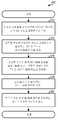
도 5는 QoS 정보와 함께 리소스 요청들을 송신하기 위한 프로세스(500)의 설계를 보여준다. 프로세스(500)는 단말 또는 몇몇 다른 엔티티에 의하여 수행될 수 있다. 단말은 다수의 구성들 중에서 리소스 요청들을 송신하기 위해 사용하도록 선택되는 구성을 결정하거나 수신할 수 있다(블럭 512). 각각의 구성은 다수의 가능한 QoS 타입들 중 적어도 하나와 연관될 수 있다. 일 설계에서, 다수의 가능한 QoS 타입들은 QoS 클래스 및 레이턴시 기한을 포함한다. 단말은 선택된 구성에 기초하여 리소스 요청들에서 송신하기 위한 적어도 하나의 QoS 타입을 결정할 수 있다(블럭 514).5 shows a design of a
단말은 송신하기 위한 데이터를 가질 수 있으며, 데이터에 대한 QoS 정보를 결정할 수 있다(블럭 516). QoS 정보는 선택된 구성에 대한 적어도 하나의 QoS 타입을 포함할 수 있다. 단말은 또한 송신하기 위한 데이터에 대한 백로그 레벨 정보를 결정할 수 있다(블럭 518). 백로그 레벨 정보는 모든 구성들에 대하여 적용 가능할 수 있는 다수의 백로그 레벨 값들 중 하나를 포함할 수 있다. 단말은 백로그 레벨 정보 및 QoS 정보를 포함하는 리소스 요청을 생성하여 송신할 수 있다(블럭 520).The terminal may have data for transmission and may determine QoS information for the data (block 516). The QoS information may include at least one QoS type for the selected configuration. The terminal may also determine backlog level information for the data to transmit (block 518). The backlog level information may include one of a number of backlog level values that may be applicable for all configurations. The terminal may generate and transmit a resource request including backlog level information and QoS information (block 520).
일 설계에서, 리소스 요청은 (ⅰ) 제1 구성이 선택된다면 백로그 레벨 정보 및 QoS 클래스 정보를, (ⅱ) 제2 구성이 선택된다면 QoS 클래스 정보 또는 레이턴시 기한 정보 중 하나와 백로그 레벨 정보를, 또는 (ⅲ) 제3 구성이 선택된다면 백로그 레벨 정보 및 레이턴시 기한 정보를 포함할 수 있다. 리소스 요청은 또한 다른 설계들에서 정보들의 다른 결합물들을 포함할 수 있다. 일 설계에서, 리소스 요청은 제1 구성에 대한 8개의 가능한 QoS 클래스 값들 중 하나를, 또는 제2 구성에 대한 4개의 가능한 QoS 클래스 값들 중 하나를 포함할 수 있다. 일 설계에서, 리소스 요청은 제2 구성에 대한 4개의 가능한 레이턴시 기한 값들 중 하나를 또는 제3 구성에 대한 8개의 가능한 레이턴시 기한 값들 중 하나를 포함할 수 있다. 제1 구성은 플로우들의 제1 개수의 플로우들(예를 들어, 8개 플로우들)에 대하여 선택될 수 있으며, 제2 구성은 제2 개수의 플로우들(예를 들어, 4개 플로우들)에 대하여 선택될 수 있다. 리소스 요청은 모든 구성들에 대하여 고정된 개수의 비트들(예를 들어, 6개의 비트들)을 포함할 수 있다.In one design, the resource request includes (i) backlog level information and QoS class information if the first configuration is selected, and (ii) one of QoS class information or latency time information and backlog level information if the second configuration is selected. Or (iii) a third configuration, if selected, may include backlog level information and latency time information. The resource request may also include other combinations of information in other designs. In one design, the resource request may include one of eight possible QoS class values for the first configuration, or one of four possible QoS class values for the second configuration. In one design, the resource request may include one of four possible latency deadline values for the second configuration or one of eight possible latency deadline values for the third configuration. The first configuration may be selected for a first number of flows (eg, eight flows) of flows, and the second configuration may be selected for a second number of flows (eg, four flows). Can be selected. The resource request may include a fixed number of bits (eg, six bits) for all configurations.
도 6은 QoS 정보와 함께 리소스 요청들을 송신하기 위한 장치(600)의 설계를 보여준다. 장치(600)는 리소스 요청들을 송신하는데 사용하기 위하여 선택되는 구성을 결정하거나 수신하기 위한 수단(모듈 612), 선택된 구성에 기초하여 리소스 요청들에서 송신하기 위하여 적어도 하나의 QoS 타입을 결정하기 위한 수단(모듈 614), 송신하기 위한 데이터에 대하여 QoS 정보를 결정하기 위한 수단 - QoS 정보는 선택된 구성에 대한 적어도 하나의 QoS 타입을 포함함 - (모듈 616), 송신하기 위한 데이터에 대하여 백로그 레벨 정보를 결정하기 위한 수단(모듈 618), 및 백로그 레벨 정보 및 QoS 정보를 포함하는 리소스 요청을 생성하여 송신하기 위한 수단(모듈 620)을 포함한다.6 shows a design of an
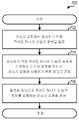
도 7은 상이한 포맷들을 갖는 리소스 요청들을 송신하기 위한 프로세스(700)의 설계를 보여준다. 프로세스(700)는 단말 또는 몇몇 다른 엔티티에 의하여 수행될 수 있다. 단말은 리소스 요청에서 송신하기 위한 적어도 하나의 타입의 정보를 결정할 수 있다(블럭 712). 단말은 송신하기 위한 적어도 하나의 타입의 정보에 기초하여 다수의 포맷들 중에서 리소스 요청을 위해 사용하기 위한 포맷을 결정할 수 있다(블럭 714). 다수의 포맷들은 백로그 레벨 정보 및 QoS 정보에 대한 제1 포맷 및 단지 백로그 레벨 정보에 대한 제2 포맷을 포함할 수 있다. 단말은 적어도 하나의 타입의 정보가 백로그 레벨 정보 및 QoS 정보를 포함한다면 제1 포맷을 사용할 수 있다. 단말은 적어도 하나의 타입의 정보가 단지 백로그 레벨 정보를 포함한다면 제2 포맷을 사용할 수 있다. 단말은 리소스 요청이 특정 스트림에 대한 것이라면 제1 포맷을 사용할 수 있으며, 리소스 요청이 다수의 스트림들에 대한 것이라면 제2 포맷을 사용할 수 있다. 단말은 QoS 정보와 연관되는 스트림에 대하여 제1 포맷을 사용할 수 있으며, 가변 QoS 정보를 갖는 다수의 스트림들 또는 QoS 정보와 연관되지 않는 스트림에 대하여 제2 포맷을 사용할 수 있다. 단말은 다른 기준에 기초하여 제1 또는 제2 포맷을 또한 선택할 수 있다.7 shows a design of a
단말은 결정된 포맷으로 적어도 하나의 타입의 정보를 포함하는 리소스 요청을 생성할 수 있다(블럭 716). 리소스 요청은 다수의 포맷들 모두에 대하여 고정된 개수의 비트들(예를 들어, 6개의 비트들)을 포함할 수 있다. 제1 포맷은 리소스 요청에 대한 제1 범위의 값들(예를 들어, 0 내지 47)에 대응할 수 있으며, 제2 포맷은 제2 범위의 값들(예를 들어, 48 내지 63)에 대응할 수 있다.The terminal may generate a resource request including at least one type of information in the determined format (block 716). The resource request may include a fixed number of bits (eg, six bits) for all of the multiple formats. The first format may correspond to a first range of values (eg, 0 to 47) for the resource request, and the second format may correspond to a second range of values (eg, 48 to 63).
도 8은 상이한 포맷들을 갖는 리소스 요청들을 송신하기 위한 장치(800)의 설계를 보여준다. 장치(800)는 리소스 요청에서 송신하기 위한 적어도 하나의 타입의 정보를 결정하기 위한 수단(모듈 812), 송신하기 위한 적어도 하나의 타입의 정보에 기초하여 다수의 포맷들 중에서 리소스 요청을 위해 사용하기 위한 포맷을 결정하기 위한 수단(모듈 814), 및 결정된 포맷으로 적어도 하나의 타입의 정보를 포함하는 리소스 요청을 생성하기 위한 수단(모듈 816)을 포함한다.8 shows a design of an
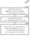
도 9는 QoS 정보를 갖는 리소스 요청들을 송신하기 위한 프로세스(900)의 설계를 보여준다. 프로세스(900)는 단말 또는 몇몇 다른 엔티티에 의하여 수행될 수 있다. 단말은 송신하기 위한 데이터에 대한 QoS 클래스 정보 또는 레이턴시 기한 정보를 결정할 수 있다(블럭 912). 단말은 송신하기 위한 데이터에 대한 백로그 레벨 정보를 결정할 수 있다(블럭 914). 단말은 제1 필드에서 백로그 레벨 정보를, 그리고 제2 필드에서 QoS 클래스 정보 또는 레이턴시 기한 정보를 포함하는 리소스 요청을 생성할 수 있다(블럭 916).9 shows a design of a
블럭(912)의 일 설계에서, 단말은 송신하기 위한 데이터가 속하는 적어도 하나의 스트림을 식별할 수 있으며, 적어도 하나의 스트림이 QoS 클래스와 연관되는지 또는 레이턴시 기한과 연관되는지를 결정할 수 있다. 단말은 그 후 (ⅰ) QoS 클래스와 연관된다면 적어도 하나의 스트림에 대한 QoS 클래스 정보를, 또는 (ⅱ) 레이턴시 기한과 연관된다면 적어도 하나의 스트림에 대한 레이턴시 기한 정보를 결정할 수 있다.In one design of
블럭(916)의 일 설계에서, 단말은 (ⅰ) QoS 클래스 정보를 제2 필드에 대한 제1 범위의 값들에 맵핑하거나, 또는 (ⅱ) 레이턴시 기한 정보를 제2 필드에 대한 제2 범위의 값들에 맵핑할 수 있다. 일 설계에서, 제2 필드는 3개의 비트들을 포함할 수 있으며, 단말은 (ⅰ) QoS 클래스 정보를 제2 필드에 대한 4개의 가능한 값들 중 하나에 맵핑하거나, 또는 (ⅱ) 레이턴시 기한 정보를 제2 필드에 대한 4개의 상이한 가능한 값들 중 하나에 맵핑할 수 있다.In one design of
도 10은 QoS 정보와 함께 리소스 요청들을 송신하기 위한 장치(1000)의 일 설계를 보여준다. 장치(1000)는 송신하기 위한 데이터에 대한 QoS 클래스 정보 또는 레이턴시 기한 정보를 결정하기 위한 수단(모듈 1012), 송신하기 위한 데이터에 대한 백로그 레벨 정보를 결정하기 위한 수단(모듈 1014), 및 제1 필드에서 백로그 레벨 정보를 그리고 제2 필드에서 QoS 클래스 정보 또는 레이턴시 기한 정보를 포함하는 리소스 요청을 생성하기 위한 수단(모듈 1016)을 포함한다.10 shows a design of an
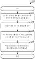
도 11은 스펙트럼 효율을 고려함으로써 리소스 요청들을 송신하기 위한 프로세스(1100)의 설계를 보여준다. 프로세스(1100)는 단말 또는 몇몇 다른 엔티티에 의하여 수행될 수 있다. 단말은 스펙트럼 효율 및 송신하기 위한 데이터량에 기초하여 백로그 레벨 정보를 결정할 수 있다(블럭 1112). 단말은 가장 최신의 리소스 들의 할당, 가장 최신의 CQI, 등에 기초하여 스펙트럼 효율을 결정할 수 있다. 단말은 백로그 레벨 정보를 포함하는 리소스 요청을 생성할 수 있다(블럭 1114).11 shows a design of a
일 설계에서, 단말은 예를 들어, 표 1 또는 5에서 보여지는 바와 같이, 스펙트럼 효율만큼 스케일링되는(scaled) 상이한 개수의 바이트들에 대응하는 다수의 백로그 레벨 값들 중 하나를 선택할 수 있다. 다른 설계에서, 단말은 예를 들어, 표1에 보여지는 바와 같이, (ⅰ) 스펙트럼 효율이 임계값보다 크다면 스펙트럼 효율에 의하여 스케일링되는 상이한 개수의 바이트들에, 또는 (ⅱ) 스펙트럼 효율이 임계값 이하라면 상이한 개수의 바이트들에 대응하는 다수의 백로그 레벨 값들 중 하나를 선택할 수 있다. 또 다른 설계에서, 단말은 예를 들어, 표 1 또는 5에 보여지는 바와 같이, 스펙트럼 효율에 기초하여 결정되는 상이한 개수의 타일들에 대응하는 다수의 백로그 레벨 값들 중 하나를 선택할 수 있다. 단말은 또한 다른 방식들로 다수의 백로그 레벨 값들 중 하나를 선택할 수 있다. 모든 설계들에 대하여, 단말은 선택된 백로그 레벨 값을 포함하는 리소스 요청을 생성할 수 있다.In one design, the terminal may select one of a plurality of backlog level values corresponding to different numbers of bytes scaled by spectral efficiency, for example, as shown in Tables 1 or 5. In another design, as shown in Table 1, for example, the terminal may (i) have different numbers of bytes scaled by the spectral efficiency if the spectral efficiency is greater than the threshold, or (ii) the spectral efficiency is critical. If it is below the value, one of the plurality of backlog level values corresponding to the different number of bytes can be selected. In another design, the terminal may select one of a plurality of backlog level values corresponding to different numbers of tiles determined based on spectral efficiency, for example, as shown in Table 1 or 5. The terminal may also select one of the plurality of backlog level values in other ways. For all designs, the terminal can generate a resource request that includes the selected backlog level value.
도 12는 스펙트럼 효율을 고려함으로써 리소스 요청들을 송신하기 위한 장치(1200)의 설계를 보여준다. 장치(1200)는 스펙트럼 효율 및 송신하기 위한 데이터량에 기초하여 백로그 레벨 정보를 결정하기 위한 수단(모듈 1212) 및 백로그 레벨 정보를 포함하는 리소스 요청을 생성하기 위한 수단(모듈 1214)을 포함한다.12 shows a design of an
도 13은 백오프와 함께 제어 메시지들을 송신하기 위한 프로세스(1300)의 설계를 보여준다. 프로세스(1300)는 단말 또는 몇몇 다른 엔티티에 의하여 수행될 수 있다. 단말은 제1 제어 메시지, 예를 들어, 송신하기 위한 데이터에 대한 리소 스 요청, 핸드오프 요청, CQI 리포트, 등을 송신할 수 있다(블럭 1312). 단말은 윈도우 내에 제1 의사-랜덤 값을 선택할 수 있으며(블럭 1314), 제1 제어 메시지를 송신 시, 제1 의사-랜덤 값으로 백오프 타이머를 설정할 수 있다(블럭 1316).13 shows a design of a
단말은 백오프 타이머에 기초하여 제2 제어 메시지를 송신할지 여부를 결정할 수 있다(블럭 1318). 일 설계에서, 단말은 응답이 제1 제어 메시지에 대하여 수신되지 않고(예를 들어, 리소스 요청에 대하여 할당이 수신되지 않음) 백오프 타이머가 만료되면, 제2 제어 메시지를 송신할 수 있다. 단말은 제2 제어 메시지를 송신한 이후에 윈도우를 증가시키고, 증가된 윈도우 내에 제2 의사-랜덤 값을 선택하며, 제2 제어 메시지를 송신시 제2 의사-랜덤 값으로 백오프 타이머를 설정할 수 있다. 단말은 그 후 백오프 타이머에 기초하여 다른 제어 메시지를 송신할지 여부를 결정할 수 있다.The terminal may determine whether to transmit a second control message based on the backoff timer (block 1318). In one design, the terminal may transmit a second control message if a response is not received for the first control message (eg, no assignment is received for the resource request) and the backoff timer expires. The terminal may increase the window after transmitting the second control message, select a second pseudo-random value within the increased window, and set a backoff timer as the second pseudo-random value when transmitting the second control message. have. The terminal may then determine whether to send another control message based on the backoff timer.
일 설계에서, 제어 메시지들은 리소스 요청들이고, 단말은 (ⅰ) 스트림이 제1 리소스 요청에서 시그널링되는 적어도 하나의 스트림의 가장 높은 우선순위보다 더 높은 우선순위를 갖는다면, (ⅱ) 스트림이 가장 짧은 레이턴시 기한을 갖고 가장 짧은 레이턴시 기한이 제1 리소스 요청에서 시그널링되지 않는다면, 또는 (ⅲ) 몇몇 다른 기준이 충족된다면, 백오프 타이머가 만료되기 이전에 스트림에 대한 제2 리소스 요청을 송신할 수 있다.In one design, the control messages are resource requests, and if (i) the stream has a higher priority than the highest priority of at least one stream signaled in the first resource request, (ii) the stream is shortest; If there is a latency deadline and the shortest latency deadline is not signaled in the first resource request, or (i) some other criteria are met, then a second resource request for the stream may be sent before the backoff timer expires.
도 14는 백오프와 함께 제어 메시지들을 송신하기 위한 장치(1400)의 설계를 보여준다. 장치(1400)는 제1 제어 메시지, 예를 들어, 송신하기 위한 데이터에 대한 리소스 요청을 송신하기 위한 수단(모듈 1412), 윈도우 내에 제1 의사랜덤 값을 선택하기 위한 수단(모듈 1414), 제1 제어 메시지를 송신시 제1 의사-랜덤 값으로 백오프 타이머를 설정하기 위한 수단(모듈 1416), 및 백오프 타이머에 기초하여 제2 제어 메시지를 송신할지 여부를 결정하기 위한 수단(모듈 1418)을 포함한다.14 shows a design of an
도 6, 8, 10, 12 및 14의 모듈들은 프로세서들, 전자 디바이스들, 하드웨어 디바이스들, 전자 컴포넌트들, 논리 회로들, 메모리들, 등 또는 그들의 결합물들을 포함할 수 있다.6, 8, 10, 12, and 14 may include processors, electronic devices, hardware devices, electronic components, logic circuits, memories, and the like or combinations thereof.
도 15는 기지국(110) 및 단말(120)의 설계의 블럭도를 보여주며, 이는 도 1의 기지국들 중 하나이고, 단말들 중 하나이다. 상기 설계에서, 단말(120)은 T개의 안테나들(1534a 내지 1534t)를 구비하고, 기지국(110)은 R개의 안테나들(1552a 내지 1552r)을 구비하며, 일반적으로 T ≥ 1이고, R ≥ 1이다.15 shows a block diagram of the design of
단말(120)에서, 송신(TX) 데이터 및 제어 프로세서(1520)는 데이터 소스(1512)로부터 트래픽 데이터를 수신하고, 트래픽 데이터를 프로세싱(예를 들어, 인코딩, 인터리빙(interleave), 스크램블링(scramble) 및 심볼 맵핑)하며, 데이터 심볼들을 제공할 수 있다. 프로세서(1520)는 또한 제어기/프로세서(1540)로부터 제어 정보(예를 들어, 리소스 요청들)를 수신하고, 제어 정보를 프로세싱하며, 제어 심볼들을 제공할 수 있다. 프로세서(1520)는 또한 제어 심볼들 및 데이터를 갖는 파일럿 심볼들을 생성하여 멀티플렉싱할 수 있다. TX MIMO 프로세서(1530)는 프로세서(1520)로부터 심볼들을 프로세싱(예를 들어, 프리코딩(precode)하고, T개 변조기들(MOD)(1532a 내지 1532t)로 T개 출력 심볼 스트림들을 제공할 수 있다. TX MIMO 프로세서(1530)는 장비가 단일 안테나를 구비한다면 제거될 수 있다. 각각의 변조기(1532)는 자신의 출력 심볼 스트림(예를 들어, OFDM, CDM 등에 대한)을 프로세싱하여 출력 칩 스트림을 획득할 수 있다. 각각의 변조기(1532)는 역방향 링크 신호를 생성하기 위하여 자신의 출력 칩 스트림을 추가로 조정(예를 들어, 아날로그로 변환, 필터링, 증폭 및 상향변환)할 수 있다. 변조기들(1532a 내지 1532t)로부터의 T개의 역방향 링크 신호들은 각각 T개의 안테나들(1534a 내지 1534t)을 통해 송신될 수 있다.At
기지국(110)에서, 안테나들(1552a 내지 1552r)은 단말(120) 및/또는 다른 단말들로부터 역방향 링크 신호들을 수신할 수 있다. 각각의 안테나(1552)는 개별적인 복조기(DEMOD)(1554)로 수신된 신호를 제공할 수 있다. 각각의 복조기(1554)는 샘플들을 획득하기 위하여 자신의 수신된 신호를 조정(예를 들어, 필터링, 증폭, 하향변환, 및 디지털화)할 수 있으며, 복조된 심볼들을 획득하기 위하여 샘플들을 추가로 프로세싱(예를 들어, OFDM, CDM, 등에 대하여)할 수 있다. RX MIMO 프로세서(1560)는 모든 R개 복조기들(1554a 내지 1554r)로부터 복조된 심볼들상에 MIMO 검출을 수행하고, 검출된 심볼들을 제공할 수 있다. 수신(RX) 데이터 및 제어 프로세서(1570)는 검출된 심볼들을 프로세싱(예를 들어, 복조, 디인터리빙, 디스크램블링 및 디코딩)하고, 데이터 싱크(1572)로 디코딩된 데이터를 제공하며, 제어기/프로세서(1590)로 디코딩된 제어 정보(예를 들어, 리소스 요청)를 제공할 수 있다. 일반적으로, 프로세서들(1560 및 1570)에 의한 프로세싱은 각각 단말(120)에서 프로세서들(1530 및 1520)에 의한 프로세싱에 대하여 상보적이다.At
기지국(110)은 순방향 링크상에서 트래픽 데이터 및/또는 제어 정보를 단 말(120)로 송신할 수 있다. 데이터 소스(1578)로부터의 트래픽 데이터 및/또는 제어기/프로세서(1590)로부터의 제어 정보(예를 들어, 리소스 할당들)는 제어 프로세서(1580) 및 TX 데이터에 의하여 프로세싱되고, TX MIMO 프로세서(1582)에 의하여 추가로 프로세싱되어, R개의 출력 심볼 스트림들을 획득할 수 있다. R개의 변조기들(1554a 내지 1554r)은 R개의 출력 칩 스트림들을 획득하기 위하여 R개의 출력 심볼 스트림들을 프로세싱(예를 들어, OFDM에 대하여)할 수 있으며, R개의 순방향 링크 신호들을 획득하기 위하여 출력 칩 스트림들을 추가로 조정할 수 있으며, 상기 순방향 링크 신호들은 R개의 안테나들(1552a 내지 1552r)을 통해 송신될 수 있다. 단말(120)에서, 기지국(110)으로부터의 순방향 링크 신호들은 안테나들(1534a 내지 1534t)에 의하여 수신되고, 복조기들(1532a 내지 1532t)에 의하여 조정되고 프로세싱되며, 단말(120)로 송신되는 트래픽 데이터 및 제어 정보를 복구하기 위하여 RX MIMO 프로세서(1536)(적용가능하다면) 및 RX 데이터 및 제어 프로세서(1538)에 의하여 추가로 프로세싱될 수 있다. 트래픽 데이터는 데이터 싱크(1539)로 제공될 수 있다.
제어기들/프로세서들(1540 및 1590)은 각각 단말(120) 및 기지국(110)에서의 동작을 지시할 수 있다. 메모리들(1542 및 1592)은 각각 단말(120) 및 기지국(110)에 대한 데이터 및 프로그램 코드들을 저장할 수 있다. 스케줄러(1594)는 순방향 및/또는 역방향 링크상에서의 데이터 송신을 이해 단말들을 스케줄링할 수 있으며, 스케줄링된 단말들로 리소스들을 할당할 수 있다.Controllers /
본 발명의 기술 분야에서 통상의 지식을 가진 자는 정보 및 신호들이 임의의 다양한 상이한 기술들 및 기법들을 이용하여 표현될 수 있다는 것을 이해할 것이다. 예를 들어, 위의 설명에서 참조될 수 있는 데이터, 지시들, 명령들, 정보, 신호들, 비트들, 심볼들 및 칩들은 전압들, 전류들, 전자기파들, 자기장들 또는 입자들, 광학장들 또는 입자들, 또는 이들의 임의의 결합에 의해 표현될 수 있다.One of ordinary skill in the art will understand that information and signals may be represented using any of a variety of different technologies and techniques. For example, data, instructions, instructions, information, signals, bits, symbols, and chips that may be referenced in the above description may include voltages, currents, electromagnetic waves, magnetic fields or particles, optical fields. Or particles, or any combination thereof.
본 발명의 기술 분야에서 통상의 지식을 가진 자는 여기에 개시된 실시예들과 관련하여 설명된 다양한 예시적인 논리 블록들, 모듈들, 회로들, 및 알고리즘 단계들이 전자 하드웨어, 컴퓨터 소프트웨어, 또는 이 둘의 결합물로서 구현될 수 있다는 것을 이해할 것이다. 하드웨어 및 소프트웨어의 이러한 상호 호환성을 명확하게 설명하기 위해, 다양한 예시적인 컴포넌트들, 블록들, 모듈들, 회로들 및 단계들이 이들의 기능과 관련하여 위에서 일반적으로 설명되었다. 이러한 기능이 하드웨어 또는 소프트웨어로서 구현되는지 여부는 특정한 애플리케이션 및 전체 시스템에 대하여 부과되는 설계 제약들에 따라 좌우된다. 본 발명의 기술 분야에서 통상의 지식을 가진 자는 각각의 특정한 애플리케이션에 대하여 다양한 방식들로 설명된 기능을 구현할 수 있으나, 이러한 구현 결정들은 본 발명의 범위를 벗어나는 것으로 해석되어서는 안 될 것이다.One of ordinary skill in the art would appreciate that the various illustrative logical blocks, modules, circuits, and algorithm steps described in connection with the embodiments disclosed herein may be implemented in electronic hardware, computer software, or both. It will be appreciated that it can be implemented as a combination. To clearly illustrate this interchangeability of hardware and software, various illustrative components, blocks, modules, circuits, and steps have been described above generally in terms of their functionality. Whether such functionality is implemented as hardware or software depends on the particular application and design constraints imposed on the overall system. Those skilled in the art may implement the described functionality in various ways for each particular application, but such implementation decisions should not be interpreted as causing a departure from the scope of the present invention.
여기에 개시된 실시예들과 관련하여 설명된 다양한 예시적인 논리 블록들, 모듈들 및 회로들은 여기에서 설명되는 기능들을 수행하도록 설계된 범용 프로세서, 디지털 신호 프로세서(DSP), 주문형 집적 회로(ASIC), 필드 프로그래밍가능한 게이트 어레이(FPGA) 또는 다른 프로그래밍가능한 로직 장치, 이산 게이트 또는 트랜지스터 로직, 이산 하드웨어 컴포넌트들 또는 이들의 임의의 조합을 통해 구현되 거나 또는 수행될 수 있다. 범용 프로세서는 마이크로프로세서일 수 있으나, 대안적으로 범용 프로세서는 임의의 기존의 프로세서, 제어기, 마이크로콘트롤러 또는 상태 머신일 수 있다. 프로세서는 또한 컴퓨팅 장치들의 조합, 예를 들어, DSP 및 마이크로프로세서의 조합, 복수의 마이크로프로세서들, DSP 코어와 연결된 하나 이상의 마이크로프로세서들 또는 임의의 다른 이러한 구성으로서 구현될 수 있다.The various illustrative logical blocks, modules, and circuits described in connection with the embodiments disclosed herein are general purpose processors, digital signal processors (DSPs), application specific integrated circuits (ASICs), fields designed to perform the functions described herein. It may be implemented or performed through a programmable gate array (FPGA) or other programmable logic device, discrete gate or transistor logic, discrete hardware components, or any combination thereof. A general purpose processor may be a microprocessor, but in the alternative, the general purpose processor may be any conventional processor, controller, microcontroller, or state machine. The processor may also be implemented as a combination of computing devices, e.g., a combination of a DSP and a microprocessor, a plurality of microprocessors, one or more microprocessors in conjunction with a DSP core, or any other such configuration.
여기에서 제시되는 실시예들과 관련하여 설명되는 방법 또는 알고리즘의 단계들은 하드웨어로 직접 구현되거나, 프로세서에 의해 실행되는 소프트웨어 모듈로 구현되거나, 또는 이들의 결합에 의해 구현될 수 있다. 소프트웨어 모듈은 RAM 메모리, 플래시 메모리, ROM 메모리, EPROM 메모리, EEPROM 메모리, 레지스터들, 하드 디스크, 이동식 디스크, CD-ROM, 또는 본 기술분야에 공지된 임의의 다른 형태의 저장 매체와 같은 데이터 메모리에 저장될 수 있다. 예시적인 저장 매체는 프로세서에 연결될 수 있으며, 그 결과 프로세서는 저장 매체로부터 정보를 판독하고 저장 매체로 정보를 기록할 수 있다. 대안적으로, 저장 매체는 프로세서로 통합될 수 있다. 프로세서 및 저장 매체는 ASIC 내에 포함될 수 있다. ASIC은 사용자 단말 내에 상주할 수 있다. 대안적으로, 프로세서 및 저장 매체는 사용자 단말 내에 개별적인 컴포넌트들로서 상주할 수 있다.The steps of a method or algorithm described in connection with the embodiments presented herein may be implemented directly in hardware, in a software module executed by a processor, or by a combination thereof. The software module may be stored in a data memory such as RAM memory, flash memory, ROM memory, EPROM memory, EEPROM memory, registers, hard disk, removable disk, CD-ROM, or any other form of storage medium known in the art. Can be stored. An exemplary storage medium can be coupled to the processor, such that the processor can read information from and write information to the storage medium. Alternatively, the storage medium may be integrated into the processor. The processor and the storage medium may be included within an ASIC. The ASIC may reside in a user terminal. In the alternative, the processor and the storage medium may reside as discrete components in a user terminal.
하나 이상의 예시적인 실시예에서, 설명한 기능들은 하드웨어, 소프트웨어, 펌웨어, 또는 이들의 임의의 조합으로 구현될 수 있다. 소프트웨어에 구현된다면, 이 기능들은 컴퓨터 판독 가능 매체 상에 하나 이상의 명령 또는 코드로서 저장될 수도 있고 이를 통해 전송될 수 있다. 컴퓨터 판독 가능 매체는 한 장소에서 다른 장소로 컴퓨터 프로그램의 전달을 용이하게 하는 임의의 매체를 포함하는 통신 매체 및 컴퓨터 저장 매체를 모두 포함한다. 저장 매체는 컴퓨터에 의해 액세스 가능한 임의의 이용 가능한 매체일 수 있다. 한정이 아닌 예시로, 이러한 컴퓨터 판독 가능 매체는 RAM, ROM, EEPROM, CD-ROM이나 다른 광 디스크 저장소, 자기 디스크 저장소 또는 다른 자기 저장 소자, 또는 명령이나 데이터 구조의 형태로 원하는 프로그램 코드를 운반 또는 저장하는데 사용될 수 있으며 컴퓨터에 의해 액세스 가능한 임의의 다른 매체를 포함할 수 있다. 또한, 임의의 접속이 컴퓨터 판독 가능 매체로 적절히 지칭된다. 예를 들어, 소프트웨어가 동축 케이블, 광섬유 케이블, 꼬임쌍선, 디지털 가입자 회선(DSL), 또는 적외선, 라디오 및 초고주파와 같은 무선 기술을 이용하여 웹사이트, 서버 또는 다른 원격 소스로부터 전송된다면, 동축 케이블, 광섬유 케이블, 꼬임 쌍선, DSL, 또는 적외선, 라디오 및 초고주파와 같은 무선 기술이 매체의 정의에 포함된다. 여기서 사용된 것과 같은 디스크(disk 및 disc)는 콤팩트 디스크(CD), 레이저 디스크, 광 디스크, 디지털 다목적 디스크(DVD), 플로피디스크 및 블루레이 디스크를 포함하며, 디스크(disk)들은 보통 데이터를 자기적으로 재생하는 반면, 디스크(disc)들은 데이터를 레이저에 의해 광학적으로 재생한다. 상기의 조합 또한 컴퓨터 판독 가능 매체의 범위 내에 포함되어야 한다.In one or more illustrative embodiments, the described functions may be implemented in hardware, software, firmware, or any combination thereof. If implemented in software, these functions may be stored on or transmitted over as one or more instructions or code on a computer-readable medium. Computer-readable media includes both computer storage media and communication media including any medium that facilitates transfer of a computer program from one place to another. The storage medium may be any available media that is accessible by a computer. By way of example, and not limitation, such computer-readable media may carry or transmit desired program code in the form of RAM, ROM, EEPROM, CD-ROM or other optical disk storage, magnetic disk storage, or other magnetic storage element, or instruction or data structure. It can include any other medium that can be used for storage and accessible by a computer. Also, any connection is properly termed a computer readable medium. For example, if the software is transmitted from a website, server or other remote source using coaxial cable, fiber optic cable, twisted pair, digital subscriber line (DSL), or wireless technologies such as infrared, radio and microwave, Fiber technology, twisted pair, DSL, or wireless technologies such as infrared, radio, and microwave are included in the definition of the medium. Discs as used herein (disks and discs) include compact discs (CDs), laser discs, optical discs, digital general purpose discs (DVDs), floppy discs and Blu-ray discs, which usually contain data In contrast, the discs optically reproduce data by means of a laser. Combinations of the above should also be included within the scope of computer readable media.
제시된 실시예들에 대한 설명은 임의의 본 발명의 기술 분야에서 통상의 지식을 가진 자가 본 발명을 이용하거나 또는 실시할 수 있도록 제공된다. 이러한 실시예들에 대한 다양한 변형들은 본 발명의 기술 분야에서 통상의 지식을 가진 자 에게 명백할 것이며, 여기에 정의된 일반적인 원리들은 본 발명의 범위를 벗어남이 없이 다른 실시예들에 적용될 수 있다. 그리하여, 본 발명은 여기에 제시된 실시예들로 한정되는 것이 아니라, 여기에 제시된 원리들 및 신규한 특징들과 일관되는 가장 넓은 범위에서 해석되어야 할 것이다.The description of the presented embodiments is provided to enable any person skilled in the art to make or use the present invention. Various modifications to these embodiments will be apparent to those skilled in the art, and the generic principles defined herein may be applied to other embodiments without departing from the scope of the invention. Thus, the present invention should not be limited to the embodiments set forth herein but should be construed in the broadest scope consistent with the principles and novel features set forth herein.
Claims (59)
Translated fromKoreanApplications Claiming Priority (4)
| Application Number | Priority Date | Filing Date | Title |
|---|---|---|---|
| US88734207P | 2007-01-30 | 2007-01-30 | |
| US60/887,342 | 2007-01-30 | ||
| US88819207P | 2007-02-05 | 2007-02-05 | |
| US60/888,192 | 2007-02-05 |
Publications (2)
| Publication Number | Publication Date |
|---|---|
| KR20090115187A KR20090115187A (en) | 2009-11-04 |
| KR101079994B1true KR101079994B1 (en) | 2011-11-04 |
Family
ID=39495958
Family Applications (1)
| Application Number | Title | Priority Date | Filing Date |
|---|---|---|---|
| KR1020097018136AActiveKR101079994B1 (en) | 2007-01-30 | 2008-01-30 | Resource requests for a wireless communication system |
Country Status (14)
| Country | Link |
|---|---|
| US (1) | US8743774B2 (en) |
| EP (1) | EP2111723B1 (en) |
| JP (1) | JP4988865B2 (en) |
| KR (1) | KR101079994B1 (en) |
| CN (2) | CN101595750A (en) |
| AU (1) | AU2008210413B2 (en) |
| BR (1) | BRPI0807851B1 (en) |
| CA (1) | CA2675577C (en) |
| ES (1) | ES2544584T3 (en) |
| IL (1) | IL199824A0 (en) |
| MX (1) | MX2009008072A (en) |
| RU (1) | RU2437254C2 (en) |
| TW (1) | TWI479900B (en) |
| WO (1) | WO2008095042A2 (en) |
Families Citing this family (17)
| Publication number | Priority date | Publication date | Assignee | Title |
|---|---|---|---|---|
| US8892108B2 (en)* | 2007-01-30 | 2014-11-18 | Qualcomm Incorporated | Control channel constraints in wireless communications |
| US8069433B2 (en)* | 2007-04-18 | 2011-11-29 | Microsoft Corporation | Multi-format centralized distribution of localized resources for multiple products |
| US9288024B2 (en)* | 2007-09-12 | 2016-03-15 | Apple Inc. | Systems and methods for uplink signaling using time-frequency resources |
| US9974060B2 (en) | 2007-09-12 | 2018-05-15 | Apple Inc. | Systems and methods for uplink signalling |
| US8203992B2 (en) | 2008-09-17 | 2012-06-19 | Qualcomm Incorporated | Methods and systems for implementing CDMA-based dedicated control channels in an OFDMA-based network |
| US8295373B2 (en)* | 2008-09-30 | 2012-10-23 | Intel Corporation | Virtual multicarrier design for orthogonal frequency division multiple access communications |
| WO2010042578A1 (en)* | 2008-10-08 | 2010-04-15 | Citrix Systems, Inc. | Systems and methods for real-time endpoint application flow control with network structure component |
| US8434336B2 (en)* | 2009-11-14 | 2013-05-07 | Qualcomm Incorporated | Method and apparatus for managing client initiated transmissions in multiple-user communication schemes |
| KR101655269B1 (en)* | 2010-05-28 | 2016-09-07 | 삼성전자주식회사 | Apparatus and method for resource segmetation in wireless communication system |
| CN102487489A (en)* | 2010-12-03 | 2012-06-06 | 华为技术有限公司 | Message sending method, message processing method and device |
| SG192171A1 (en)* | 2011-12-21 | 2013-08-30 | Panasonic Corp | Image coding method, image decoding method, image coding apparatus and image decoding apparatus |
| KR102348214B1 (en)* | 2015-05-28 | 2022-01-07 | 삼성전자 주식회사 | Method and apparatus for scheduling in a wireless communication system |
| US10638369B2 (en)* | 2016-12-20 | 2020-04-28 | Qualcomm Incorporated | Quality of service configuration based on channel quality |
| US10805424B2 (en) | 2017-06-29 | 2020-10-13 | Bank Of America Corporation | System for sending digital requests for resource transfers |
| CN111130726B (en)* | 2018-10-31 | 2022-06-24 | 华为技术有限公司 | A communication processing method and related equipment for uplink resource request |
| EP4266743A4 (en)* | 2021-01-29 | 2024-01-17 | Huawei Technologies Co., Ltd. | Resource scheduling method and apparatus |
| US12206592B2 (en)* | 2021-11-05 | 2025-01-21 | Qualcomm Incorporated | Techniques for deadline-aware scheduling |
Citations (2)
| Publication number | Priority date | Publication date | Assignee | Title |
|---|---|---|---|---|
| WO2004075468A2 (en)* | 2003-02-18 | 2004-09-02 | Qualcomm Incorporated | Scheduled and autonomous transmission and acknowledgement |
| WO2006138339A2 (en) | 2005-06-16 | 2006-12-28 | Qualcomm Incorporated | Methods and apparatus for efficient providing of scheduling information |
Family Cites Families (33)
| Publication number | Priority date | Publication date | Assignee | Title |
|---|---|---|---|---|
| US5603081A (en)* | 1993-11-01 | 1997-02-11 | Telefonaktiebolaget Lm Ericsson | Method for communicating in a wireless communication system |
| US5936965A (en)* | 1996-07-08 | 1999-08-10 | Lucent Technologies, Inc. | Method and apparatus for transmission of asynchronous, synchronous, and variable length mode protocols multiplexed over a common bytestream |
| US6778558B2 (en)* | 1998-02-23 | 2004-08-17 | Lucent Technologies Inc. | System and method for incremental redundancy transmission in a communication system |
| US6594240B1 (en) | 1998-05-22 | 2003-07-15 | Lucent Technologies Inc. | Methods and apparatus for random backoff based access priority in a communications system |
| US7103065B1 (en)* | 1998-10-30 | 2006-09-05 | Broadcom Corporation | Data packet fragmentation in a cable modem system |
| KR100401191B1 (en) | 1999-02-13 | 2003-10-10 | 삼성전자주식회사 | Apparatus and method for controlling transmission of reverse link in cdma comminication system |
| SE514361C2 (en) | 1999-06-04 | 2001-02-12 | Ericsson Telefon Ab L M | Method and device in mobile packet data network |
| JP4879436B2 (en) | 2000-02-23 | 2012-02-22 | マイクロソフト コーポレーション | Quality of service over communication paths with wireless links |
| US6934752B1 (en)* | 2000-03-23 | 2005-08-23 | Sharewave, Inc. | Quality of service extensions for multimedia applications in wireless computer networks |
| US6754506B2 (en) | 2000-06-13 | 2004-06-22 | At&T Wireless Services, Inc. | TDMA communication system having enhanced power control |
| US7039032B1 (en)* | 2000-07-14 | 2006-05-02 | At&T Corp. | Multipoll for QoS-Driven wireless LANs |
| US6804222B1 (en)* | 2000-07-14 | 2004-10-12 | At&T Corp. | In-band Qos signaling reference model for QoS-driven wireless LANs |
| EP1332640B1 (en)* | 2000-11-07 | 2007-02-21 | Nokia Corporation | Method and system for uplink scheduling of packet data traffic in wireless system |
| EP1223776A1 (en) | 2001-01-12 | 2002-07-17 | Siemens Information and Communication Networks S.p.A. | A collision free access scheduling in cellular TDMA-CDMA networks |
| US7047016B2 (en) | 2001-05-16 | 2006-05-16 | Qualcomm, Incorporated | Method and apparatus for allocating uplink resources in a multiple-input multiple-output (MIMO) communication system |
| KR100797461B1 (en) | 2001-09-29 | 2008-01-24 | 엘지전자 주식회사 | Packet Data Transmission Method in Communication System |
| US7336967B2 (en)* | 2002-07-08 | 2008-02-26 | Hughes Network Systems, Llc | Method and system for providing load-sensitive bandwidth allocation |
| GB2395398B (en) | 2002-11-07 | 2007-05-23 | Motorola Inc | A communication unit and method of communicating measurement reports therefor |
| US20050041673A1 (en)* | 2003-08-20 | 2005-02-24 | Frances Jiang | Method of managing wireless network resources to gateway devices |
| WO2005032185A1 (en) | 2003-09-30 | 2005-04-07 | Telefonaktiebolaget Lm Ericsson (Publ) | System and method for reporting measurements in a communication system |
| US8406235B2 (en)* | 2003-11-26 | 2013-03-26 | Qualcomm Incorporated | Quality of service scheduler for a wireless network |
| KR100606062B1 (en) | 2004-02-26 | 2006-07-26 | 삼성전자주식회사 | Method of controlling transmission of channel quality information according to characteristics of time-varying channel in mobile communication system |
| JP4438493B2 (en) | 2004-04-21 | 2010-03-24 | 日本電気株式会社 | Mobile communication system, radio base station, mobile station, and transmission power control method used therefor |
| US20060092963A1 (en)* | 2004-10-28 | 2006-05-04 | Ajay Bakre | Architecture and method for efficient application of QoS in a WLAN |
| US7924871B2 (en)* | 2004-11-24 | 2011-04-12 | Nextel Communications Inc. | Control channel priority access systems and methods |
| JP4711750B2 (en) | 2005-04-13 | 2011-06-29 | 株式会社エヌ・ティ・ティ・ドコモ | Mobile communication system, mobile station, base station, and communication control method |
| US7564822B2 (en)* | 2005-05-19 | 2009-07-21 | Alcatel-Lucent Usa Inc. | Method of reverse link transmission in a wireless network using code and frequency multiplexing |
| US20070253449A1 (en)* | 2005-12-22 | 2007-11-01 | Arnab Das | Methods and apparatus related to determining, communicating, and/or using delay information |
| US20070171849A1 (en)* | 2006-01-03 | 2007-07-26 | Interdigital Technology Corporation | Scheduling channel quality indicator and acknowledgement/negative acknowledgement feedback |
| US20080080469A1 (en)* | 2006-10-02 | 2008-04-03 | Nokia Corporation | Method and apparatus for reporting in a communication network |
| EP2119300A2 (en)* | 2007-01-05 | 2009-11-18 | Interdigital Technology Corporation | Backoff mechanism in random access channel |
| CN101617553A (en)* | 2007-01-08 | 2009-12-30 | 诺基亚公司 | Method, device and system for providing reports on channel quality of a communication system |
| US8892108B2 (en)* | 2007-01-30 | 2014-11-18 | Qualcomm Incorporated | Control channel constraints in wireless communications |
- 2008
- 2008-01-29USUS12/021,819patent/US8743774B2/enactiveActive
- 2008-01-30EPEP08728615.9Apatent/EP2111723B1/enactiveActive
- 2008-01-30WOPCT/US2008/052531patent/WO2008095042A2/enactiveApplication Filing
- 2008-01-30KRKR1020097018136Apatent/KR101079994B1/enactiveActive
- 2008-01-30CNCNA2008800033510Apatent/CN101595750A/enactivePending
- 2008-01-30RURU2009132471/07Apatent/RU2437254C2/enactive
- 2008-01-30MXMX2009008072Apatent/MX2009008072A/enactiveIP Right Grant
- 2008-01-30AUAU2008210413Apatent/AU2008210413B2/enactiveActive
- 2008-01-30CNCN201610135887.4Apatent/CN105636123B/enactiveActive
- 2008-01-30TWTW097103537Apatent/TWI479900B/enactive
- 2008-01-30CACA2675577Apatent/CA2675577C/enactiveActive
- 2008-01-30BRBRPI0807851-3Apatent/BRPI0807851B1/enactiveIP Right Grant
- 2008-01-30JPJP2009548431Apatent/JP4988865B2/enactiveActive
- 2008-01-30ESES08728615.9Tpatent/ES2544584T3/enactiveActive
- 2009
- 2009-07-13ILIL199824Apatent/IL199824A0/enunknown
Patent Citations (2)
| Publication number | Priority date | Publication date | Assignee | Title |
|---|---|---|---|---|
| WO2004075468A2 (en)* | 2003-02-18 | 2004-09-02 | Qualcomm Incorporated | Scheduled and autonomous transmission and acknowledgement |
| WO2006138339A2 (en) | 2005-06-16 | 2006-12-28 | Qualcomm Incorporated | Methods and apparatus for efficient providing of scheduling information |
Also Published As
| Publication number | Publication date |
|---|---|
| EP2111723B1 (en) | 2015-05-27 |
| RU2437254C2 (en) | 2011-12-20 |
| CN105636123B (en) | 2021-06-01 |
| CN105636123A (en) | 2016-06-01 |
| RU2009132471A (en) | 2011-03-10 |
| ES2544584T3 (en) | 2015-09-01 |
| TW200850025A (en) | 2008-12-16 |
| US8743774B2 (en) | 2014-06-03 |
| AU2008210413B2 (en) | 2012-01-12 |
| KR20090115187A (en) | 2009-11-04 |
| CA2675577C (en) | 2015-11-24 |
| TWI479900B (en) | 2015-04-01 |
| EP2111723A2 (en) | 2009-10-28 |
| BRPI0807851A2 (en) | 2014-05-27 |
| CN101595750A (en) | 2009-12-02 |
| JP2010517490A (en) | 2010-05-20 |
| AU2008210413A1 (en) | 2008-08-07 |
| WO2008095042A2 (en) | 2008-08-07 |
| WO2008095042A3 (en) | 2009-01-15 |
| BRPI0807851B1 (en) | 2020-03-03 |
| IL199824A0 (en) | 2010-04-15 |
| JP4988865B2 (en) | 2012-08-01 |
| MX2009008072A (en) | 2009-08-18 |
| US20080186931A1 (en) | 2008-08-07 |
| CA2675577A1 (en) | 2008-08-07 |
Similar Documents
| Publication | Publication Date | Title |
|---|---|---|
| KR101079994B1 (en) | Resource requests for a wireless communication system | |
| KR101019001B1 (en) | Method and apparatus for efficiently providing scheduling information | |
| JP4823177B2 (en) | Apparatus and method for multiplexing enhanced uplink | |
| TWI361586B (en) | Methods and apparatus for flexible spectrum allocation in communication systems | |
| TWI359582B (en) | Cdma wireless communication systems | |
| JP2025111735A (en) | Transmitting device, receiving device, transmitting method, receiving method, and integrated circuit | |
| JP4772121B2 (en) | Method, base station, mobile station and medium for reducing interference to downlink broadcast signals | |
| CN113939039B (en) | Communication device, communication method, and integrated circuit | |
| US20070274288A1 (en) | Sharing resources in a wireless communication system | |
| WO2007117757A2 (en) | Scheduling in wireless communication systems | |
| TW200828898A (en) | Physical layer superframe, frame, preamble and control header for IEEE 802.22 WRAN communication systems | |
| KR20080033966A (en) | Downlink traffic channel resource allocation method and data transmission method of multi-carrier HSDPA | |
| KR101405947B1 (en) | Resource Allocation Method in Broadband Wireless Access System | |
| CN1385047A (en) | Method for dynamic allocation of resources in digital radio communication system | |
| KR20100010498A (en) | Method for allocating group resource in a broadband wireless access system | |
| HK1138712A (en) | Resource requests for a wireless communication system | |
| KR20030037397A (en) | Apparatus for transmitting/receiving transprot format resource set in communication system using high speed downlink packet access scheme and method therof | |
| HK1103490A (en) | Methods and apparatus for flexible spectrum allocation in communication systems |
Legal Events
| Date | Code | Title | Description |
|---|---|---|---|
| A201 | Request for examination | ||
| PA0105 | International application | St.27 status event code:A-0-1-A10-A15-nap-PA0105 | |
| PA0201 | Request for examination | St.27 status event code:A-1-2-D10-D11-exm-PA0201 | |
| PG1501 | Laying open of application | St.27 status event code:A-1-1-Q10-Q12-nap-PG1501 | |
| E902 | Notification of reason for refusal | ||
| PE0902 | Notice of grounds for rejection | St.27 status event code:A-1-2-D10-D21-exm-PE0902 | |
| E13-X000 | Pre-grant limitation requested | St.27 status event code:A-2-3-E10-E13-lim-X000 | |
| P11-X000 | Amendment of application requested | St.27 status event code:A-2-2-P10-P11-nap-X000 | |
| P13-X000 | Application amended | St.27 status event code:A-2-2-P10-P13-nap-X000 | |
| E701 | Decision to grant or registration of patent right | ||
| PE0701 | Decision of registration | St.27 status event code:A-1-2-D10-D22-exm-PE0701 | |
| GRNT | Written decision to grant | ||
| PR0701 | Registration of establishment | St.27 status event code:A-2-4-F10-F11-exm-PR0701 | |
| PR1002 | Payment of registration fee | St.27 status event code:A-2-2-U10-U12-oth-PR1002 Fee payment year number:1 | |
| PG1601 | Publication of registration | St.27 status event code:A-4-4-Q10-Q13-nap-PG1601 | |
| R18-X000 | Changes to party contact information recorded | St.27 status event code:A-5-5-R10-R18-oth-X000 | |
| FPAY | Annual fee payment | Payment date:20140929 Year of fee payment:4 | |
| PR1001 | Payment of annual fee | St.27 status event code:A-4-4-U10-U11-oth-PR1001 Fee payment year number:4 | |
| FPAY | Annual fee payment | Payment date:20150930 Year of fee payment:5 | |
| PR1001 | Payment of annual fee | St.27 status event code:A-4-4-U10-U11-oth-PR1001 Fee payment year number:5 | |
| FPAY | Annual fee payment | Payment date:20160929 Year of fee payment:6 | |
| PR1001 | Payment of annual fee | St.27 status event code:A-4-4-U10-U11-oth-PR1001 Fee payment year number:6 | |
| FPAY | Annual fee payment | Payment date:20170929 Year of fee payment:7 | |
| PR1001 | Payment of annual fee | St.27 status event code:A-4-4-U10-U11-oth-PR1001 Fee payment year number:7 | |
| FPAY | Annual fee payment | Payment date:20180928 Year of fee payment:8 | |
| PR1001 | Payment of annual fee | St.27 status event code:A-4-4-U10-U11-oth-PR1001 Fee payment year number:8 | |
| FPAY | Annual fee payment | Payment date:20190924 Year of fee payment:9 | |
| PR1001 | Payment of annual fee | St.27 status event code:A-4-4-U10-U11-oth-PR1001 Fee payment year number:9 | |
| PR1001 | Payment of annual fee | St.27 status event code:A-4-4-U10-U11-oth-PR1001 Fee payment year number:10 | |
| PR1001 | Payment of annual fee | St.27 status event code:A-4-4-U10-U11-oth-PR1001 Fee payment year number:11 | |
| PR1001 | Payment of annual fee | St.27 status event code:A-4-4-U10-U11-oth-PR1001 Fee payment year number:12 | |
| PR1001 | Payment of annual fee | St.27 status event code:A-4-4-U10-U11-oth-PR1001 Fee payment year number:13 | |
| PR1001 | Payment of annual fee | St.27 status event code:A-4-4-U10-U11-oth-PR1001 Fee payment year number:14 | |
| PR1001 | Payment of annual fee | St.27 status event code:A-4-4-U10-U11-oth-PR1001 Fee payment year number:15 |