KR101079903B1 - Apparatus and method for controlling speed in Automatic Train Operation - Google Patents
Apparatus and method for controlling speed in Automatic Train OperationDownload PDFInfo
- Publication number
- KR101079903B1 KR101079903B1KR1020090078059AKR20090078059AKR101079903B1KR 101079903 B1KR101079903 B1KR 101079903B1KR 1020090078059 AKR1020090078059 AKR 1020090078059AKR 20090078059 AKR20090078059 AKR 20090078059AKR 101079903 B1KR101079903 B1KR 101079903B1
- Authority
- KR
- South Korea
- Prior art keywords
- speed
- profile
- train
- target
- limit
- Prior art date
- Legal status (The legal status is an assumption and is not a legal conclusion. Google has not performed a legal analysis and makes no representation as to the accuracy of the status listed.)
- Active
Links
Images


Classifications
- B—PERFORMING OPERATIONS; TRANSPORTING
- B61—RAILWAYS
- B61L—GUIDING RAILWAY TRAFFIC; ENSURING THE SAFETY OF RAILWAY TRAFFIC
- B61L15/00—Indicators provided on the vehicle or train for signalling purposes
- B61L15/0062—On-board target speed calculation or supervision
- B—PERFORMING OPERATIONS; TRANSPORTING
- B61—RAILWAYS
- B61L—GUIDING RAILWAY TRAFFIC; ENSURING THE SAFETY OF RAILWAY TRAFFIC
- B61L15/00—Indicators provided on the vehicle or train for signalling purposes
- B61L15/0058—On-board optimisation of vehicle or vehicle train operation
- B—PERFORMING OPERATIONS; TRANSPORTING
- B61—RAILWAYS
- B61L—GUIDING RAILWAY TRAFFIC; ENSURING THE SAFETY OF RAILWAY TRAFFIC
- B61L27/00—Central railway traffic control systems; Trackside control; Communication systems specially adapted therefor
- B61L27/04—Automatic systems, e.g. controlled by train; Change-over to manual control
- B—PERFORMING OPERATIONS; TRANSPORTING
- B61—RAILWAYS
- B61L—GUIDING RAILWAY TRAFFIC; ENSURING THE SAFETY OF RAILWAY TRAFFIC
- B61L2201/00—Control methods
Landscapes
- Engineering & Computer Science (AREA)
- Mechanical Engineering (AREA)
- Electric Propulsion And Braking For Vehicles (AREA)
- Train Traffic Observation, Control, And Security (AREA)
Abstract
Translated fromKoreanDescription
Translated fromKorean본 발명은 열차자동운전(Automatic Train Operation)에서의 속도 제어장치 및 방법에 관한 것이다.The present invention relates to an apparatus and method for speed control in automatic train operation.
보다 상세하게는 제한속도 프로파일을 만족하고, 또한 열차를 가속 주행 또는 감속 주행할 경우에 가속도 한계 및 저크 한계를 준수하여 탑승객들이 불편함을 느끼지 않도록, 열차가 주행할 각각의 위치에서 열차가 주행해야 할 속도를 추정하여 제어하는 열차자동운전에서의 속도 제어장치 및 방법에 관한 것이다.More specifically, the train must travel at each location the train will travel in order to meet the speed limit profile and to ensure that passengers do not feel uncomfortable by following the acceleration and jerk limits when accelerating or decelerating the train. The present invention relates to a speed control apparatus and method for automatic train operation for estimating and controlling a speed to be performed.
철도 분야에서 신호제어설비는 열차가 주행할 경우에 사고의 발생을 방지하고, 안전한 열차 운전이 이루어질 수 있도록 하며, 열차 운용의 효율을 높이기 위한 각종 신호장치의 기술 및 제어시스템의 기술들로 구성된다.In the field of railway, the signal control system consists of various signal device technology and control system technology to prevent the occurrence of accidents when the train is running, to enable safe train operation, and to improve the efficiency of train operation. .
신호제어설비는 열차진로를 제어하는 설비인 궤도회로장치, 연동장치, 선로전환기장치 및 열차집중제어장치와, 열차들 간의 간격을 제어하는 설비인 폐색장 치, 열차자동정지장치, 열차자동제어, 열차자동운전, 그리고 기타 운전보안 및 정보화 목적의 설비 등으로 분류된다.Signal control equipment is a track circuit device, an interlock device, a line changer device and a train intensive control device that controls the train path, an occlusion device that controls the distance between trains, a train automatic stop device, train automatic control, It is classified as automatic train operation and other facilities for driving security and information.
이러한 신호제어설비들 중에서 상기 열차자동운전은 열차의 가속, 감속 및 정차와 같은 기능을 자동으로 수행하여 열차의 운전능률을 향상시키는 것이다.Among these signal control facilities, the train automatic driving is to automatically perform functions such as acceleration, deceleration and stop of the train to improve the driving efficiency of the train.
상기 자동열차운전은 주어진 주행조건 및 선로에 맞추어 주행계획을 사전에 입안하는 방식과, 일정 거리 주행시의 다양한 속도 패턴을 미리 저장하여 두고, 조건에 적합한 속도 패턴을 선택하여 주행계획을 세우는 방식 등이 알려져 있다.The automatic train operation includes a method of preparing a driving plan in advance according to a given driving condition and a track, and storing a variety of speed patterns in a certain distance in advance, and selecting a speed pattern suitable for a condition to establish a driving plan. Known.
상기 주어진 주행조건 및 선로에 맞추어 주행계획을 사전에 입안하는 방식은 특정 주행구간에 대하여 각각의 위치에서 열차의 속도 제어 패턴을 사전에 결정하고, 결정한 속도 제어 패턴에 따라 열차의 속도를 추종시키는 방식으로 열차를 운전하는 것이다.The method of drawing up a driving plan in advance according to the given driving conditions and tracks is a method of pre-determining a speed control pattern of a train at each position for a specific driving section and following the speed of the train according to the determined speed control pattern. To drive the train.
그러나 선행 열차의 지연 등으로 인하여 열차의 주행 상태가 주행 계획에서 크게 벗어나는 경우에 사전에 정해진 계획을 수정하기 어렵기 때문에 운행상의 지연이 발생하고, 발생한 지연시간을 따라잡기가 어렵다. 또한 외란 등으로 인하여 열차가 주행 계획에서 벗어나는 경우에 계획을 수정하기 어려우며, 이 경우 사전에 정해진 계획을 무리하게 추종하게 되면, 주행 계획에 반영한 에너지 절약이나 승차감 등의 목표가 달성되기 어렵다. 또한 선로 조건 및 선로 상태가 바뀌는 등의 주행 계획을 수정할 필요가 있을 경우에 유연하게 대처할 수 없다.However, when the driving state of the train is significantly out of the driving plan due to the delay of the preceding train, it is difficult to modify the predetermined plan, and thus, the operation delay occurs and it is difficult to catch up with the delay time. In addition, when the train deviates from the driving plan due to disturbance, etc., it is difficult to modify the plan. In this case, if the following predetermined plan is forcibly followed, goals such as energy saving or riding comfort reflected in the driving plan are difficult to be achieved. In addition, it is not possible to flexibly cope with the need to modify the driving plan such as changing track conditions and track conditions.
그리고 상기 일정 거리 주행시의 다양한 속도 패턴을 미리 저장하여 두고, 조건에 적합한 속도 패턴을 선택하여 주행계획을 세우는 방식은 다수의 속도 패턴을 계속 조합하여 목표 지점까지의 전체 주행 계획을 세울 수 있다. 또한 조건지령장치는 열차의 현재 위치와 미리 입력되어 있는 노선 정보를 비교하고, 속도제한구간에 접근하는 경우에 이를 검지하여 다이어그램에 얼마나 여유가 있고 선행 열차에 얼마나 접근하였는가 등의 여러 조건을 검토하여 적절한 패턴을 선택하고, 지령을 내린다.In addition, the various speed patterns at the time of driving the predetermined distance are stored in advance, and a driving pattern is selected by selecting a speed pattern suitable for a condition, and thus, the overall driving plan to the target point may be made by continuously combining a plurality of speed patterns. In addition, the condition command device compares the current position of the train with the pre-input route information, detects when approaching the speed limit section, and examines various conditions such as how much space is available in the diagram and how close to the preceding train. Choose the appropriate pattern and give the command.
그러나 열차의 속도 패턴을 어떤 방식으로 변경시키면서 운행하는가에 대한 기준이 명확하지 않을 수 있다. 즉, 최적의 상태를 판별하는 조건이 명확하지 않을 경우에 지령장치가 주어진 조건에서 최적의 패턴을 찾는다는 보장을 하기 어렵다. 또한 모든 속도 패턴을 가지고 있는 것이 아니므로 모든 경우에서 만족스러운 결과를 얻기가 어렵다.However, the criteria for how to change the speed pattern of trains may not be clear. That is, it is difficult to guarantee that the command apparatus finds the optimum pattern under the given condition when the condition for determining the optimum state is not clear. In addition, not all speed patterns have satisfactory results in all cases.
그리고 대한민국 등록특허 제10-435983호에서는 트랙회로부터 목표속도를 수신하여 가속도한계 및 저크한계를 준수하면서 현재속도에서 목표속도로 가기 위한 저크 프로파일을 구하고 이를 적분하여 가속도 프로파일 및 속도 프로파일을 구하며, 그 구한 속도 프로파일을 열차가 추종하도록 한다.In the Republic of Korea Patent No. 10-435983, receiving the target speed from the track rotation to obtain the jerk profile to go to the target speed from the current speed while complying with the acceleration limit and jerk limit, to obtain the acceleration profile and the speed profile by integrating the Let the train follow the speed profile you find.
그러나 상기 대한민국 등록특허 제10-435983호는 시간 기반의 프로파일을 사용하므로 추종제어가 잘 이루어지지 않아 주행 상태가 주행 계획으로부터 빗나가는 경우에 위치 에러를 보정하기 어렵다. 특히 열차를 감속 운전할 경우에 문제가 될 수 있는 것으로서 특정 지점에서 열차의 속도가 속도 제한 값을 만족해야 하는 경 우에, 시간에 따라 프로파일을 추종하는 경우에는 속도제한을 만족하는 위치에 에러가 생기는 것을 보정하는 것이 곤란하다. 즉, 속도-시간 그래프에서 아래쪽 부분의 면적은 열차의 이동거리로서 속도 프로파일을 추종하는 경우에 목표 프로파일과 실제 주행 기록 사이의 오차가 발생하면 결과적으로 속도-시간 그래프에서 아래쪽 부분의 면적에 오차가 발생할 수 있고, 일시적으로라도 추종에 문제가 생기는 경우에 이를 회복할 수 없다.However, since the Republic of Korea Patent No. 10-435983 uses a time-based profile, it is difficult to correct the position error when the driving state deviates from the driving plan due to poor tracking control. In particular, when decelerating the train, it may be a problem. When the speed of the train must satisfy the speed limit value at a certain point, when following the profile according to time, an error occurs at the position that satisfies the speed limit. It is difficult to correct. That is, if the area of the lower part of the speed-time graph follows the speed profile as the travel distance of the train, and if an error occurs between the target profile and the actual driving record, the area of the lower part of the speed-time graph is consequently. It may occur, and even if it is temporarily lost, it cannot be recovered.
이러한 이유로 인하여 열차를 자동으로 정지시키는 경우에도 시간기반 프로파일을 사용하는 것에는 한계가 따르게 된다.For this reason, there is a limit to using a time-based profile even when the train is stopped automatically.
또한 단순히 현재속도에서 목표속도로 도달하기 위한 일반적인 형태의 프로파일 계산법만을 제안하고 있다. 또한 일정 저크 - 일정 가속도 - 일정 저크의 세 구간으로 나뉘어지는 프로파일을 제안하고 있는데, 복잡한 제한속도 프로파일이 주어지는 경우에는 다양한 패턴이 발생할 수 있으므로 위의 프로파일 계산 패턴 하나만으로는 대응하기 어렵다. 즉, 위의 기법만으로는 위치에 따른 임의의 제한속도 프로파일에 대응하기 어렵고, 따라서 열차자동운전의 유연성에 제약이 발생하게 된다.In addition, we only propose a general form of profile calculation to reach the target speed from the current speed. In addition, we propose a profile that is divided into three sections: constant jerk, constant acceleration, and constant jerk. When a complex speed limit profile is given, various patterns can occur, so it is difficult to respond to the above profile calculation pattern alone. That is, the above technique alone is difficult to cope with any speed limit profile according to the position, and thus, the flexibility of automatic train operation occurs.
그러므로 본 발명이 해결하고자 하는 과제는 선로 상황, 열차 간격 및 다이어그램의 변경 등을 포함하는 다양한 조건을 고려하여 도출한 구간별 제한속도 프 로파일이 지상신호시스템으로부터 수신될 경우에 승객들의 승차감을 위하여 가속도 한계 및 저크 한계를 준수하면서 구간별 제한속도 프로파일 내에서 최적의 주행성능을 도출할 수 있는 위치 기반의 속도 프로파일을 도출하고, 도출한 속도 프로파일을 추종하도록 열차를 제어하여 열차자동운전에서 원하는 주행성능 및 정차 성능을 얻을 수 있도록 하는 열차자동운전에서의 속도 제어장치 및 방법을 제공한다.Therefore, the problem to be solved by the present invention is for passengers' ride comfort when the speed limit profile for each section, which is derived from various conditions including track conditions, train intervals and diagram changes, is received from the ground signal system. Drive the desired driving in train automatic operation by deriving the position-based speed profile that can derive the optimum driving performance within the speed limit profile for each section while complying with the acceleration limit and jerk limit, and controlling the train to follow the derived speed profile. Provided are a speed control device and a method for automatic train operation to obtain performance and stopping performance.
본 발명이 이루고자 하는 기술적 과제들은 상기에서 언급한 기술적 과제들로 제한되지 않고, 언급되지 않은 또 다른 기술적 과제들은 아래의 기재로부터 본 발명이 속하는 기술 분야에서 통상의 지식을 가진 자가 명확하게 이해될 수 있을 것이다.Technical problems to be achieved by the present invention are not limited to the above-mentioned technical problems, and other technical problems not mentioned above may be clearly understood by those skilled in the art to which the present invention pertains. There will be.
본 발명의 열차자동운전에서의 속도 제어장치는, 제한속도 프로파일 제공부가 제공하는 제한속도 프로파일을 이용하여 열차를 자동 운전할 각 위치에서의 목표속도를 계산하여 위치-속도 프로파일을 제공하는 자동운전 속도 프로파일 계산부와, 열차의 현재위치 및 주행속도를 계산하는 속도/위치 계산부와, 상기 속도/위치 계산부가 계산한 열차의 현재위치에서의 목표속도를 상기 자동운전 속도 프로파일 계산부가 제공하는 위치-속도 프로파일에서 탐색하는 목표속도 탐색부와, 상기 속도/위치 계산부가 계산한 열차의 주행속도에서 상기 목표속도 탐색부가 탐색한 목표속도를 감산하여 속도오차를 검출하는 감산기와, 상기 감산기가 검출한 속도오차 에 따라 열차의 추진 또는 제동명령을 발생하는 추진/제동 계산부를 포함하여 구성됨을 특징으로 한다.Speed control apparatus in automatic train operation of the present invention, using the speed limit profile provided by the speed limit profile providing unit calculates the target speed at each position to automatically drive the train to provide a position-speed profile A speed-position calculation unit for calculating a current position and a traveling speed of a train, and a position-velocity provided by the automatic driving speed profile calculator for a target speed at the current position of the train calculated by the speed / position calculation unit. A target speed search unit for searching in a profile, a subtractor for detecting a speed error by subtracting a target speed searched by the target speed search unit from the traveling speed of the train calculated by the speed / position calculation unit, and a speed error detected by the subtractor It is characterized in that it comprises a propulsion / braking calculation unit for generating a propulsion or braking command of the train according to The.
상기 제한속도 프로파일은 구간별로 열차가 주행할 제한속도의 정보가 포함되는 것을 특징으로 한다.The speed limit profile is characterized in that the information on the speed limit to run the train for each section.
상기 자동운전 속도 프로파일 계산부는 상기 제한속도 프로파일에서 열차를 가속 주행시켜 도달해야 할 가속 목표점, 열차를 등속 주행시켜 도달해야 할 등속 목표점 및 열차를 감속 주행시켜 도달해야 할 감속 목표점을 추출하고, 열차의 출발위치와 상기 가속 목표점, 등속 목표점 및 감속 목표점들 사이의 구간을 구분하여 각 구간별로 위치-속도 프로파일을 계산하는 것을 특징으로 한다.The automatic driving speed profile calculation unit extracts an acceleration target point to be accelerated by driving the train in the speed limit profile, a constant velocity target point to be reached by driving the train at constant speed, and a deceleration target point to be reached by decelerating the train, It is characterized by calculating the position-speed profile for each section by separating the section between the starting position and the acceleration target point, the constant velocity target point and the deceleration target point.
상기 위치-속도 프로파일의 계산은 상기 각각의 구간별로 시간-속도 프로파일을 계산하고, 계산한 시간-속도 프로파일을 이용하여 시간-위치 프로파일을 계산한 후 시간-속도 프로파일 및 시간-위치 프로파일을 이용하여 위치-속도 프로파일을 계산하는 것을 특징으로 한다.The calculation of the position-velocity profile calculates a time-velocity profile for each section, calculates a time-position profile using the calculated time-velocity profile, and then uses a time-velocity profile and a time-position profile. Calculate a position-velocity profile.
상기 자동운전 속도 프로파일 계산부가 제공하는 위치-속도 프로파일을 저장하는 데이터베이스를 더 포함하고, 상기 목표속도 탐색부는 상기 데이터베이스에서 목표속도를 탐색하는 것을 특징으로 한다.The apparatus may further include a database storing a position-speed profile provided by the automatic driving speed profile calculation unit, wherein the target speed search unit searches for a target speed in the database.
상기 제한속도 프로파일 제공부는 지상장치에 설치되어 차상장치로 제한속도 프로파일을 무선 전송하고, 상기 자동운전 속도 프로파일 계산부는 차상장치에 설치되고, 상기 제한속도 프로파일 제공부가 무선 전송하는 제한속도 프로파일로 위치-속도 프로파일을 계산하여 상기 데이터베이스에 저장하는 것을 특징으로 한다.The speed limit profile providing unit is installed in the ground apparatus and wirelessly transmits the speed limit profile to the on-vehicle apparatus, and the automatic driving speed profile calculation unit is installed in the on-vehicle apparatus, and the speed limit profile providing unit is positioned as the speed limit profile wirelessly transmitting. The speed profile is calculated and stored in the database.
상기 제한속도 프로파일 제공부 및 자동운전 속도 프로파일 계산부는 지상장치에 설치되고, 상기 자동운전 속도 프로파일 계산부가 제공하는 위치-속도 프로파일을 차상장치로 전송하여 상기 데이터베이스에 저장하는 것을 특징으로 한다.The speed limit profile providing unit and the automatic driving speed profile calculating unit are installed in the ground apparatus, and transmits the position-speed profile provided by the automatic driving speed profile calculating unit to the on-vehicle device and stores them in the database.
상기 제한속도 프로파일 제공부 및 자동운전 속도 프로파일 계산부는 차상장치에 설치되는 것을 특징으로 한다.The speed limit profile providing unit and the automatic driving speed profile calculation unit are installed in the on-vehicle device.
그리고 본 발명의 열차자동운전에서의 속도 제어방법은, 제한속도 프로파일 제공부가 제공하는 제한속도 프로파일을 이용하여 자동운전 속도 프로파일 계산부가, 열차를 자동 운전할 각 위치에서의 목표속도를 계산하여 위치-속도 프로파일을 제공하는 단계와, 속도/위치 계산부가 열차의 현재위치 및 열차의 주행속도를 계산하는 단계와, 상기 열차의 현재위치에서의 목표속도를 목표속도 탐색부가 상기 위치-속도 프로파일에서 탐색하는 단계와, 상기 열차의 주행속도에서 상기 탐색한 목표속도를 감산하여 속도오차를 검출하는 단계와, 상기 검출한 속도오차에 따라 열차의 추진 또는 제동명령을 발생하는 단계를 포함하여 구성됨을 특징으로 한다.And the speed control method in automatic train operation of the present invention, using the speed limit profile provided by the speed limit profile providing unit, the automatic driving speed profile calculation unit calculates the target speed at each position to automatically drive the train position-speed Providing a profile; calculating, by a speed / position calculating unit, a current position of a train and a traveling speed of a train; and searching by a target speed search unit in the position-speed profile for a target speed at the current position of the train; And subtracting the searched target speed from the traveling speed of the train to detect a speed error, and generating a propulsion or braking command of the train according to the detected speed error.
상기 위치-속도 프로파일을 제공하는 단계는 상기 제한속도 프로파일에서 열차를 가속 주행시켜 도달해야 할 가속 목표점, 열차를 등속 주행시켜 도달해야 할 등속 목표점 및 열차를 감속 주행시켜 도달해야 할 감속 목표점을 추출하는 단계와, 열차의 출발위치와 상기 추출한 가속 목표점, 등속 목표점 및 감속 목표점들 사이의 구간을 구분하는 단계와, 상기 구분한 각각의 구간별로 열차의 각각의 위치에서 열차가 주행할 속도를 계산하여 위치-속도 프로파일을 제공하는 것을 특징으 로 한다.The providing of the position-speed profile may include extracting an acceleration target point to be accelerated by driving the train, a constant velocity target point to be reached by driving the train at constant speed, and a deceleration target point to be reached by decelerating the train. And dividing a section between the starting position of the train and the extracted acceleration target point, constant velocity target point and deceleration target point, and calculating a speed at which the train will travel at each position of the train for each of the divided sections. -Provide a velocity profile.
상기 위치-속도 프로파일을 제공하는 단계는 상기 구분한 각각의 구간별로 시간-속도 프로파일을 계산하는 단계와, 상기 계산한 시간-속도 프로파일을 이용하여 시간-위치 프로파일을 계산하는 단계와, 상기 시간-속도 프로파일 및 시간-위치 프로파일로 열차가 각각의 위치에서 주행할 속도를 검출하여 위치-속도 프로파일을 계산하고, 계산한 위치-속도 프로파일을 제공하는 단계를 포함하는 것을 특징으로 한다.The providing of the position-velocity profile may include calculating a time-velocity profile for each of the divided sections, calculating a time-position profile using the calculated time-velocity profile, and Detecting a speed at which the train will travel at each location with a speed profile and a time-position profile, calculating a position-speed profile, and providing the calculated position-speed profile.
본 발명의 열차자동운전에서의 속도 제어장치 및 방법은 승차감 및 열차의 성능을 고려하여 주어진 값인 가속도한계와 저크한계를 바탕으로 열차자동운전의 주행계획 속도 프로파일을 계산하고, 프로파일을 구하기 위해 사용하는 가속도한계 및 저크한계는, 승차감과 열차 성능에 따라 주어진 값을 바탕으로 제어기의 성능을 고려하여 어느 정도의 여유를 두고 설정할 수 있는 것으로서 열차의 최적의 운행계획을 수립할 수 있다.Speed control device and method in automatic train operation of the present invention is used to calculate the traveling plan speed profile of the automatic train operation and obtain a profile based on the acceleration limit and jerk limit, which are given values in consideration of ride comfort and train performance. The acceleration limit and jerk limit can be set with a certain margin in consideration of the performance of the controller based on a given value according to the riding comfort and train performance, and thus an optimum driving plan of the train can be established.
그리고 거리(위치) 기반의 자동운전 속도 프로파일을 생성하고 거리(위치)에 따른 제어 기준속도를 이용하여 운전하여 열차가 위치에 따른 제한속도를 준수하며 정확한 위치에 정차할 수 있다.And by creating a distance (position) based autonomous driving speed profile and driving using the control reference speed according to the distance (position), the train can stop at the correct position while complying with the speed limit according to the position.
또한 열차의 주행 중에 임의의 제한속도 프로파일에 대응하여 유연하게 자동운전 주행계획을 수립하고 수정할 수 있다.In addition, it is possible to flexibly establish and modify the autonomous driving plan corresponding to any speed limit profile while the train is running.
이하의 상세한 설명은 예시에 지나지 않으며, 본 발명의 실시 예를 도시한 것에 불과하다. 또한 본 발명의 원리와 개념은 가장 유용하고, 쉽게 설명할 목적으로 제공된다.The following detailed description is only illustrative, and merely illustrates embodiments of the present invention. In addition, the principles and concepts of the present invention are provided for the purpose of explanation and most useful.
따라서, 본 발명의 기본 이해를 위한 필요 이상의 자세한 구조를 제공하고자 하지 않았음은 물론 통상의 지식을 가진 자가 본 발명의 실체에서 실시될 수 있는 여러 가지의 형태들을 도면을 통해 예시한다.Accordingly, various forms that can be implemented by those of ordinary skill in the art, as well as not intended to provide a detailed structure beyond the basic understanding of the present invention through the drawings.
도 1은 열차자동운전 시스템의 구성을 보인 도면이다. 여기서, 부호 100은 열차가 주행하는 선로의 인접 위치에 설치되는 지상(地上)장치이다. 상기 지상장치(100)는 지상자(102) 및 제한속도 프로파일 제공부(104)를 포함하고 있다.1 is a view showing the configuration of a train automatic driving system. Here,
상기 지상자(102)는 열차가 지상자(102)가 설치되어 있는 위치를 통과할 경우에 현재 위치 등을 포함하는 지상자 정보를 무선으로 송신한다.The terrestrial 102 wirelessly transmits terrestrial information including the current location when the train passes a location where the terrestrial 102 is installed.
상기 제한속도 프로파일 제공부(104)는 구간별 제한속도 프로파일을 계산하여 무선으로 송신한다. 예를 들면, 상기 구간별 제한속도 프로파일은 선행 열차와의 거리 및 선로 조건 등에 따라 구간별로 열차가 주행해야 할 속도 및 주행거리 등의 정보를 포함하고 있다.The speed limit
부호 150은 열차에 설치되는 차상(車上)장치이다. 상기 차상장치(150)는, 속도계(152), 지상자 정보 수신부(154), 제한속도 프로파일 수신부(156), 속도 제어 장치(158), 추진/제동 명령 인터페이스부(160), 열차 추진장치(162) 및 열차 제동장치(164)를 포함한다.
상기 속도계(152)는 열차의 주행속도를 검출하여 주행속도 신호를 발생한다.The
상기 지상자 정보 수신부(154)는 상기 지상장치(100)의 지상자(102)가 전송하는 지상자 정보를 수신한다.The
상기 제한속도 프로파일 수신부(156)는 상기 지상장치(100)의 제한속도 프로파일 제공부(104)가 전송하는 제한속도 프로파일을 수신한다.The speed limit
상기 속도 제어장치(158)는 상기 속도계(152)가 발생하는 주행 속도신호, 상기 지상자 정보 수신부(154)가 수신한 지상자 정보 및 상기 제한속도 프로파일 수신부(156)가 수신한 제한속도 프로파일에 따라 열차의 주행속도를 추정하고, 추정한 주행속도에 따라 추진/제동 명령을 발생한다.The
상기 추진/제동 명령 인터페이스부(160)는 상기 속도 제어장치(158)가 발생하는 추진/제동 명령을 인터페이스한다.The propulsion / braking
상기 열차 추진장치(162)는 상기 추진/제동 명령 인터페이스부(160)가 인터페이스하는 추진명령에 따라 열차를 추진시킨다.The
상기 열차 제동장치(164)는 상기 추진/제동 명령 인터페이스부(160)가 인터페이스하는 제동명령에 따라 열차를 제동시킨다.The
도 2는 도 1의 열차자동운전 시스템에서 속도 제어장치(158)의 바람직한 실시 예의 구성을 보인 도면이다. 도 2를 참조하면, 속도 제어장치(158)는 자동운전 속도 프로파일 계산부(200), 데이터베이스(210), 속도/위치 계산부(220), 목표속도 탐색부(230), 감산기(240) 및 추진/제동 계산부(250)를 포함한다.2 is a view showing the configuration of a preferred embodiment of the
상기 자동운전 속도 프로파일 계산부(200)는 상기 제한속도 프로파일 제공부(104)가 제공하는 구간별 제한속도 프로파일에 따라 거리를 기반으로 하여 열차를 자동운전할 자동운전 속도 프로파일을 계산한다.The autonomous driving
상기 데이터베이스(210)는 상기 자동운전 속도 프로파일 계산부(200)가 계산한 자동운전 속도 프로파일을 저장한다.The
상기 속도/위치 계산부(220)는 상기 속도계(152)가 출력하는 주행속도신호와 상기 지상자 정보 수신부(154)가 수신한 지상자 정보를 이용하여 열차의 현재 위치정보와 열차의 현재 속도정보를 계산한다.The speed /
상기 목표속도 탐색부(230)는 상기 속도/위치 계산부(220)가 계산한 열차의 현재 위치에서 열차가 주행해야 될 목표속도를 상기 데이터베이스(210)에서 탐색한다.The target
상기 감산기(240)는 상기 속도/위치 계산부(220)가 계산한 열차의 현재 속도에서 상기 목표속도 탐색부(230)가 탐색한 목표속도를 감산하여 열차의 속도 오차를 계산한다.The
상기 추진/제동 계산부(250)는 상기 감산기(240)가 계산한 열차의 속도 오차에 따라 열차의 추진 또는 열차의 제동을 계산하고, 계산 결과에 따라 열차의 추진/제동 명령을 발생하여 상기 추진/제동 명령 인터페이스부(160)로 출력한다.The propulsion /
이러한 구성을 가지는 본 발명은 열차가 선로를 주행할 경우에 속도계(152)가 열차의 주행속도를 검출하여 주행속도신호를 발생하고, 발생한 주행속도신호는 속도 제어장치(158)의 속도/위치 계산부(220)로 입력된다.According to the present invention having such a configuration, when the train travels on the track, the
그리고 열차가 지상장치(100)의 지상자(102)가 설치되어 있는 위치에 도달할 경우에 지상자(102)가 전송하는 지상자 정보 즉, 열차가 현재 주행하고 있는 위치정보를 포함하는 지상자 정보를 지상자 정보 수신부(154)가 수신하여 속도 제어장치(158)의 속도/위치 계산부(220)로 입력된다.When the train reaches the position where the
또한 상기 지상장치(100)에서 해당 열차에 대한 새로운 구간별 제한속도 프로파일을 계산하고, 계산한 새로운 구간별 제한속도 프로파일을 제한속도 프로파일 제공부(104)가 무선통신 등의 매체를 통해 차상장치(150)로 송신하면, 제한속도 프로파일 수신부(156)가 상기 새로운 구간별 제한속도 프로파일을 수신하여 속도 제어장치(158)의 자동운전 속도 프로파일 계산부(200)로 입력시킨다.In addition, the
상기 구간별 제한속도 프로파일은 열차의 위치에 따른 구간별 제한속도 정보를 포함하고 있다. 예를 들면, 도 3에 도시된 바와 같이 300∼650m의 사이에서는 60㎞/h 이하의 속도로, 650∼1000m의 사이에서는 90㎞/h 이하의 속도로, 1000∼1350m의 사이에서는 40㎞/h 이하의 속도로, 1350∼1825m의 사이에서는 80㎞/h 이하의 속도로, 1825∼2000m의 사이에서는 500㎞/h 이하의 속도로 열차를 주행하라는 제한속도 정보를 포함하고 있다.The speed limit profile for each section includes speed limit information for each section according to the location of the train. For example, as shown in FIG. 3, at a speed of 60 km / h or less between 300 and 650 m, at a speed of 90 km / h or less between 650 and 1000 m, and 40 km / between 1000 and 1350 m. It includes speed limit information to run a train at a speed of h or less at a speed of 80 km / h or less between 1350 to 1825 m and a speed of 500 km / h or less between 1825 and 2000 m.
그리고 열차가 2000m의 지점까지 주행하면서 새로운 구간별 제한속도 프로파일을 받지 못한다면 열차는 2000m의 지점 이전에 정지해야 한다.And if a train travels to a point of 2000m and does not receive a new speed limit profile for each section, the train must stop before the point of 2000m.
상기 자동운전 속도 프로파일 계산부(200)는 제한속도 프로파일 수신부(156)로부터 상기 도 3에 도시된 바와 같은 구간별 제한속도 프로파일이 입력되면, 주어진 가속도한계 및 저크한계를 고려하여 열차의 각 위치에서 열차가 주행해야 할 목표속도인 자동운전 속도 프로파일을 계산한다.When the speed limit profile for each section as shown in FIG. 3 is input from the speed
상기 열차의 각 위치에 따른 자동운전 속도 프로파일이 계산되면, 자동운전 속도 프로파일 계산부(200)는 계산된 열차의 각 위치에 따른 자동운전 속도 프로파일을 데이터 베이스(210)에 저장한다.When the automatic driving speed profile is calculated according to each position of the train, the automatic driving
이와 같은 상태에서 속도/위치 계산부(220)는 속도계(152)로부터 입력되는 주행속도 신호와 지상자 정보 수신부(154)로부터 입력되는 지상자 정보를 이용하여 열차가 현재 위치하는 위치정보와, 열차의 현재 주행속도를 알리는 속도정보를 발생한다.In such a state, the speed /
즉, 상기 속도/위치 계산부(220)는 지상자 정보 수신부(154)로부터 입력되는 지상자 정보에서 열차의 현재 위치를 확인하고, 확인한 현재위치로부터, 상기 속도계(152)로부터 입력되는 주행속도 신호를 이용하여 열차가 주행하는 현재위치를 검출하여 발생한다. 또한 상기 속도/위치 계산부(220)는 상기 속도계(152)로부터 입력되는 주행속도 신호를 이용하여 열차의 현재 주행속도를 알리는 속도정보를 발생한다.That is, the speed /
상기 속도/위치 계산부(220)가 열차의 현재 위치정보를 발생하면, 목표속도 탐색부(230)가 데이터베이스(210)를 검색하여 열차가 현재위치에서 주행해야 할 목표속도를 탐색하고, 탐색한 목표속도를 감산기(240)로 출력한다.When the speed /
그러면, 감산기(240)는 상기 속도/위치 계산부(220)가 발생하는, 열차가 현재 주행하고 있는 속도에서 상기 목표속도 탐색부(230)가 탐색한 목표속도를 감산하여 열차의 속도 오차를 계산하고, 계산한 속도 오차에 따라 추진/제동 계산부(250)가 열차를 추진 또는 제동할 것인지를 계산하여 추진/제동명령을 발생한다.Then, the
상기 추진/제동 계산부(250)가 발생한 추진/제동명령은 추진/제동명령 인터페이스부(160)를 통해 열차 추진장치(160)와 열차 제동장치(164)로 전달되어 열차를 추진 또는 제동한다.The propulsion / braking command generated by the propulsion /
그러므로 상기 열차는, 상기 데이터베이스(210)에 저장된 열차의 현재위치들 각각의 속도를 추종하면서 주행하게 된다.Therefore, the train travels while following the speed of each of the current positions of the train stored in the
이러한 본 발명에 있어서, 상기 자동운전 속도 프로파일 계산부(200)가 예를 들면, 도 3에 도시된 바와 같은 구간별 제한속도 프로파일을 입력하여 열차의 각각의 위치에서 열차가 주행해야 할 목표속도인 자동운전 속도 프로파일을 계산하는 동작을 상세히 설명한다.In the present invention, the automatic driving speed
먼저 자동운전 속도 프로파일 계산부(200)는 도 3에 도시된 구간별 제한속도 프로파일을 입력하여, 도 4에 도시된 바와 같이 300m의 지점인 열차의 출발위치(400)로부터 구간별 제한속도 프로파일의 2000m 지점까지 열차를 가속 운전하여 도달해야 하는 가속 목표점(410, 420, 450)과, 열차를 등속 운전하여 도달해야 하는 등속 목표점(440, 470) 및 열차를 감속 운전하여 도달해야 하는 제한 목표점(430, 460, 480)들을 순차적으로 연결하면서 추출한다.First, the automatic driving speed
즉, 상기 자동운전 속도 프로파일 계산부(200)는 650m 지점의 가속 목표점(410)과, 1000m 지점의 가속 목표점(420) 및 제한 목표점(430)과, 1350m 지점의 등속 목표점(440)과, 1825m 지점의 가속 목표점(450)과, 1825m 지점의 제한 목표점(460)과, 2000m 지점의 등속 목표점(470)과, 2000m 지점의 제한 목표점(480)을 순차적으로 연결하면서 추출한다.That is, the automatic driving speed
상기 출발위치(400) 및 복수의 목표점(410∼480)들이 추출되면, 상기 자동운전 속도 프로파일 계산부(200)는 상기 출발위치(400) 및 복수의 목표점(410∼480)들 사이의 속도 프로파일들을 이용하여 전체 구간에 대한 속도 프로파일을 계산한다.When the starting
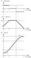
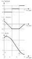
상기 출발위치(400) 및 복수의 목표점(410∼480)들 사이의 속도 프로파일을 계산할 경우에 예를 들면, 도 5 내지 도 8에 도시된 기본 속도패턴을 이용한다.When calculating the velocity profile between the starting
즉, 가속 목표점(410, 420, 450)을 향하는 경우에는 가속도 증가→등가속도→가속도 감소를 가지는 도 5의 기본 속도패턴 또는 가속도 증가→가속도 감소를 가지는 도 7의 기본 속도패턴을 이용한다.That is, when heading toward the acceleration target points 410, 420, and 450, the basic speed pattern of FIG. 5 having acceleration increase → equivalent acceleration → acceleration decrease or the basic speed pattern of FIG. 7 having acceleration increase → acceleration decrease are used.
그리고 제한 목표점(430, 460, 480)을 향하는 경우에는 가속도 감소→등가속도→가속도 증가를 가지는 도 6의 기본 속도패턴 또는 가속도감소→가속도증가를 가지는 도 8의 기본 속도패턴을 이용한다.In the case of heading toward the limit target points 430, 460, and 480, the basic speed pattern of FIG. 6 having acceleration decrease → equivalent acceleration → acceleration increase or the basic speed pattern of FIG. 8 having acceleration decrease → acceleration increase are used.
등속 목표점(440, 470)에 대해서는 열차를 고정된 속도로 주행시키면 되므로 별도의 가속 패턴 또는 감속 패턴은 필요하지 않다.For the constant speed target points 440 and 470, a separate acceleration pattern or deceleration pattern is not required because the train may be driven at a fixed speed.
열차의 초기 상태(초기 위치 li, 초기 속도 vi, 초기 가속도 ai)와 목표점에서의 열차 상태(목표위치 ltgt, 목표속도 vf, 목표가속도 af=0)와, 그리고 가속도한계(가속시 최대 amax, 감속시 최소 amin) 및 저크한계(최대 Jm, 최소 -Jm)가 주어졌을 때의 기본 속도패턴은 다음의 순서로 도출된다.The initial state of the train (initial position li , initial velocity vi , initial acceleration ai ) and the state of the train at the target point (target position ltgt , target velocity vf , target acceleration af = 0), and acceleration limit ( Given the maximum amax for acceleration, the minimum amin for deceleration, and the jerk limit (max Jm , min -Jm ), the basic velocity pattern is derived in the following order.
먼저, 가속 목표점(410, 420, 450)의 경우를 살펴보면, 첫 번째 기본 패턴에서, ti∼t1 구간, t1∼t2 구간, t2∼tf 구간에서의 프로파일은 각각 가속도 증가(최대저크), 등가속도(저크 0), 가속도 감소(최소저크)의 형태를 보인다. 패턴의 식을 결정하기 위해서는 경계 시간 t1, t2, tf의 값을 구해야 한다.First, in the case of the acceleration target points 410, 420, and 450, in the first basic pattern, the profiles in the ti to t1 sections, the t1 to t2 sections, and the t2 to tf sections respectively increase the acceleration ( Maximum jerk), equivalent speed (jerk 0), and acceleration reduction (minimum jerk). To determine the expression of the pattern, the boundary time t1 , t2 , and tf must be found.
그리고 가속도 프로파일은 저크 프로파일을 적분하여 구할 수 있고, 속도 프로파일은 가속도 프로파일을 적분하여 구할 수 있다. 초기시간 ti=0으로 두면, 전체 구간에서의 가속도 프로파일 a(t)와 속도 프로파일 v(t)는 각각 하기의 수학식 1 및 수학식 2와 같다.The acceleration profile can be obtained by integrating the jerk profile, and the velocity profile can be obtained by integrating the acceleration profile. If the initial time ti = 0, the acceleration profile a (t) and the velocity profile v (t) in the entire section are as shown in


상기 수학식 1의 가속도 프로파일 a(t)와 수학식 2의 속도 프로파일 v(t)에서 t=t1, t=t2, t=tf일 때의 경계조건을 이용하면, t1, t2, tf의 값을 구할 수 있다.Using boundary conditions when t = t1 , t = t2 , t = tf in the acceleration profile a (t) of
이 때, t1 < t2일 경우에 가속목표점(410, 420, 450)까지의 거리가 충분하여 등가속도 구간이 존재하는 것으로서 도 5에 도시된 가속도 증가→등가속도→가속도 감소를 가지는 기본 패턴을 취한다.In this case, when t1 <t2 , the distance to the acceleration target points 410, 420, and 450 is sufficient, so that there is an equivalent acceleration section, and the basic pattern having acceleration increase → equivalent acceleration → acceleration decrease shown in FIG. Take
그리고 t1 ≥ t2일 경우에는 가속목표점(410, 420, 450)까지의 거리가 짧아서 등가속도 구간이 존재하지 않는 것으로서 도 7에 도시된 바와 같이 가속도 증가→가속도 감소를 가지는 기본 패턴을 취한다.When t1 ≥ t2 , since the distance to the acceleration target points 410, 420, 450 is short, there is no equivalent acceleration section, and as shown in FIG. 7, a basic pattern having acceleration increase → acceleration decrease is taken. .
그리고 제한목표점(430, 460, 480)의 경우에는 상기 가속목표점(410, 420, 450)과 동일한 과정을 통해 제한 목표점에 따른 기본 패턴의 변수와 수학식을 결정할 수 있다.In the case of the limit target points 430, 460, and 480, variables and equations of the basic pattern according to the limit target point may be determined through the same process as the acceleration target points 410, 420, and 450.
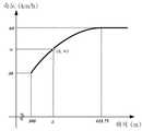
도 9는 구간별 제한속도 프로파일의 300∼650m의 구간에서 첫 번째 가속 목표점(410)에 대하여 기본 패턴을 적용하는 예를 도시하였다.9 illustrates an example of applying a basic pattern to the first
여기서, 주어진 저크한계는 Jm= 2km/h/s/s로 가정하고, 가속도한계는 최대 amax= 3km/h/s로 가정한다. 그리고 열차의 초기가속도는 0km/h/s, 초기속도는 30km/h, 초기위치는 300m로 가정한다.Here, it is assumed that the given jerk limit is Jm = 2 km / h / s / s and the acceleration limit is amax = 3 km / h / s. The initial acceleration of the train is assumed to be 0km / h / s, the initial speed is 30km / h, and the initial position is 300m.
상술한 본 발명의 방법에 따라 패턴의 변수들을 도출하면, 도 9에서와 같이 시간 11.5초가 경과한 후에 열차는 목표속도인 60Km/h에 도달하는 프로파일을 구할 수 있다.By deriving the parameters of the pattern according to the method of the present invention described above, after 11.5 seconds have elapsed as shown in FIG. 9, the train can obtain a profile that reaches a target speed of 60 km / h.
경계시간 t1, t2, tf의 값들은 각각 1.5초, 10.0초, 11.5초이고, 이 때의 열차 속도 값은 각각 32.25km/h, 57.25km/h, 60km/h이다.The threshold times t1 , t2 , and tf are 1.5 seconds, 10.0 seconds, and 11.5 seconds, respectively, and the train speed values are 32.25 km / h, 57.25 km / h, and 60 km / h, respectively.
열차의 이동거리는 상기한 바와 같이 구한 속도를 적분하여 구할 수 있고, 도 9의 패턴에서 목표속도 vf에 도달하는 시간 tf까지 열차의 이동거리는 143.75m이다.The moving distance of the train can be obtained by integrating the speed obtained as described above, and the moving distance of the train is 143.75 m until the time tf of reaching the target speed vf in the pattern of FIG. 9.
상기 143.75m의 거리는 출발위치(400)에서부터 가속 목표점(410) 사이의 거리 350m보다 짧으므로 자동운전 속도 프로파일은 300m인 지점에서 시작하여 443.75m의 지점에서 열차의 목표속도 60km/h에 도달한 후 가속목표점(410)까지 등속주행의 형태로 이어진다.Since the distance of 143.75m is shorter than 350m between the
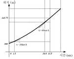
도 9에 도시된 시간-속도 프로파일에서 속도를 적분하여 각각의 시간에서의 열차 위치를 구하면, 도 10에 도시된 바와 같은 시간-위치 프로파일을 도출할 수 있다.By integrating the speed in the time-velocity profile shown in FIG. 9 to obtain the train position at each time, a time-position profile as shown in FIG. 10 can be derived.
그리고 상기 구한 시간-속도 프로파일과 시간-위치 프로파일을 시간을 매개체로 조합하면 도 11에 도시된 바와 같이 위치-속도 프로파일을 도출할 수 있다.When the time-velocity profile and the time-position profile obtained are combined with time, the position-velocity profile can be derived as shown in FIG. 11.
예를 들면, 도 11에서 시간 t일 경우에 시간-속도 프로파일에서의 속도를 vt라고 하고 시간-위치 프로파일에서의 위치를 lt라고 하면 (lt, vt)과 같은 위치-속도 프로파일에서의 값을 얻을 수 있다. 이는 열차를 자동 운전할 경우에 위치 lt에 서는 목표속도를 vt로 설정하면 된다는 것을 의미한다.For example, the time in case of time t in Figure 11 - the speed of the speed profile vt that is the time-location of the nearest profiles l Speaking oft locations, such as (lt, vt) - in the velocity profile You can get the value of. This means that when driving the train automatically, the target speed should be set to vt at position lt .
도 12에서는 컴퓨터 또는 마이크로프로세서 등에서 계산을 이용하여 위치-속도 프로파일을 도출하는 한 가지 방법을 제시하는 것으로서 아래의 과정을 통해 위치-속도 프로파일의 값을 계산할 수 있다.FIG. 12 shows one method of deriving the position-velocity profile by using a calculation in a computer or a microprocessor. The value of the position-velocity profile can be calculated through the following process.
1. 기본 가속패턴을 이용하여 시간에 따른 저크 프로파일 J(t)를 구하고, 이를 토대로 시간에 따른 기준 저크를 구하여 사용한다.1. Using the basic acceleration pattern, obtain the jerk profile J (t) over time, and use the standard jerk over time.
예를 들면, 도 12에 도시된 바와 같이 시간 tp에서는 기준저크 J(tp)=0을 사용하여 Ip를 구하고, 시간 tq에서는 기준저크 J(tp)=-2를 사용하여 Ip를 구하고,For example, as shown in FIG. 12, at time tp , Ip is obtained using the reference jerk J (tp ) = 0, and at time tq , Ip is used using the reference jerk J (tp ) =-2. Findp ,
2. 현재 계산 단계에서의 위치 및 시간은 각기 lp=l(tp), tp=p·△t(여기서, p=0, 1, 2, …이고, t0=0이며, l0=l(0)임)이고, 이전 단계인 lo부터 lp-1까지의 프로파일 {(lj, vj)│j=0, 1, 2, …, p-1}은 계산된 상태이며, 직전 상태(시간 tp-1)에서의 위치, 속도 및 가속도 lp-1, vp-1, ap-1이 저장되어 있다(초기상태: l0, v0, a0).2. The position and time in the current calculation phase are lp = l (tp ), tp = p · Δt, where p = 0, 1, 2,…, t0 = 0, and l0 = l (0) Im), and the previous step, lo profiles {(lj, vj of from up tol p-1) │j = 0 , 1, 2, ... , p-1} is the calculated state, and the position, velocity, and acceleration lp-1 , vp-1 , ap-1 at the previous state (time tp-1 ) are stored (initial state: l0 , v0 , a0 ).
3. 가속 목표점을 향하는 경우에 현재 위치에서의 기준속도 vp는 vp-1=vt일 경우에 하기의 수학식 3으로 계산할 수 있고, vi-1<vt일 경우에는 하기의 수학식 4로 계산할 수 있다.3. The reference speed vp at the current position in the case of facing the acceleration target point can be calculated by


상기 수학식 3은 가속 목표점을 향하며, 도 5에 도시된 가속도 증가→등가속도→가속도 감소를 가지는 패턴의 경우에 사용하는 수학식이다. 감속 목표점을 향하는 경우나 등가속도 구간이 없는 패턴을 사용하는 경우에도 상기 수학식 3과 마찬가지로 도 6 내지 도 8의 저크 프로파일을 적분한 속도 v(t)의 식을 유도할 수 있다.
여기서, 수학식 4의 lp는 수학식 5와 같이 이동평균을 적용하여 계산할 수도 있다.Here, lp in Equation 4 may be calculated by applying a moving average as in Equation 5.

4. 상기한 1 내지 3의 과정을 프로파일을 구하고자 하는 구간의 출발점으로부터 lp가 목표점의 위치인 lt에 도달할 때까지 반복한다.4. Repeat the
여기서, △t로 고정 값을 사용하였으나, 열차의 속도에 따라 조절되는 가변 값을 사용할 수도 있다.Here, a fixed value is used as Δt, but a variable value adjusted according to the speed of the train may be used.
도 13은 도 3에 도시한 구간별 제한속도 프로파일에 대하여 자동운전 속도 프로파일 계산부(200)가 출발위치(400)로부터 최종 위치인 제한 목표점(480)에 도달할 때까지 목표점들마다 상술한 과정을 반복 수행하여 구한 자동 위치-속도 프로파일을 예로 들어 보인 도면이다.13 is the process described above for each target point until the automatic driving speed
여기서 구간별 제한속도 프로파일에서 열차의 출발위치(400)로부터 최종 위치인 제한 목표점(480)까지 순방향으로 위치-속도 프로파일을 계산하는 과정을 설명한다.Here, the process of calculating the position-speed profile in the forward direction from the starting
300∼650m의 구간에서는 상기에서 예를 들어 제시한 것과 같이 300m 지점에서 시작하여 가속목표점(410)(650m, 60km/h)을 향해 위치-속도 프로파일을 작성하고, 650∼1000m의 구간에서는 650m 지점에서 가속목표점(420)(1000m, 90km/h)을 향해 위치-속도 프로파일을 작성하다가 중간에서 제한목표점(430)(1000m, 40km/h)으로 목표점을 전환하여 위치속도 프로파일을 작성한다.In the section of 300 to 650m, starting from the 300m point as described above, for example, the position-velocity profile is created toward the acceleration target point 410 (650m, 60km / h), and the 650m point in the 650-1000m section. At this time, the position-speed profile is created toward the acceleration target point 420 (1000m, 90km / h), and the target speed is converted to the limit target point 430 (1000m, 40km / h) in the middle to create the position speed profile.
상기한 기본 패턴을 이용하면 현재 위치로부터 특정 목표점에 도달하기 위해 필요한 거리를 구할 수 있으므로, 매 계산 단계에서 이후의 제한목표점(430)에 대해 필요한 제동거리와 실제 남은 거리를 비교하여 제동거리와 남은 거리가 같을 때 제한목표점(430)에 대한 제동 프로파일을 작성하기 시작하면 된다.Using the basic pattern described above, the distance required to reach a specific target point from the current position can be obtained. Therefore, the braking distance and the remaining distance are compared by comparing the required braking distance and the actual remaining distance for the subsequent
1000∼1350m 구간에서는 등속목표점(440)(1350m, 40km/h)을 향해 등속으로 위치-속도 프로파일을 작성하고, 1350∼1825m 구간에서는 가속목표점(450)(1350m, 80km/h)을 향해 위치-속도 프로파일을 작성하여 목표속도 80km/h에 도달한 후에는 등속으로 위치-속도 프로파일을 작성한다. 그리고 상기한 650∼1000m 구간에서와 마찬가지로 제한 목표점(460)(1825m, 50km/h)에 대해 제동이 필요한 것이 판별되면 감속 프로파일 패턴을 적용하여 제한목표점(460)(1825m, 50km/h)까지의 제동으로 위치-속도 프로파일을 작성한다.Position-velocity profiles are created at constant velocity toward the constant velocity target point 440 (1350m, 40km / h) in the range of 1000 to 1350m, and position toward the acceleration target point 450 (1350m, 80km / h) in the range of 1350 to 1825m. After creating a velocity profile and reaching the target speed of 80 km / h, create a position-velocity profile at constant velocity. When it is determined that braking is required for the limit target point 460 (1825m, 50km / h) as in the above 650 to 1000m section, the deceleration profile pattern is applied to the limit target point 460 (1825m, 50km / h). Create a position-velocity profile by braking.
마지막으로 1825∼2000m 구간에서는 제한목표점(480)(2000m, 0km/h)에 대해 제동이 필요한 시점부터 제동으로 위치-속도 프로파일을 작성하여 제한목표점(480)(2000m, 0km/h)에서 열차가 정차할 수 있는 위치-속도 프로파일을 작성한다.Lastly, in the period of 1825 to 2000m, the braking is made from the point where braking is necessary for the limit target point 480 (2000m, 0km / h) and the train is started at the limit target point 480 (2000m, 0km / h). Create a position-velocity profile that can be stopped.
상기 자동운전 속도프로파일 계산부(200)가 제한속도 프로파일을 반영하여 위치-속도 프로파일을 계산하고, 계산한 위치-속도 프로파일에 따라 열차를 주행시키고 있는 상태에서 새로운 제한속도 프로파일이 입력될 경우에 새로운 제한속도 프로파일을 반영하여 위치-속도 프로파일을 다시 계산하고, 그 다시 계산한 위치-속도 프로파일에 따라 열차를 주행시킨다.When the automatic driving speed
예를 들면, 도 14의 (a)에 도시된 바와 같이 자동운전 속도프로파일 계산부(200)가 위치-속도 프로파일을 계산하고, 계산한 위치-속도 프로파일에 따라 열차를 주행시키고 있는 상태에서 도 14의 (b)에 도시된 바와 같이 임시로 열차의 주행속도를 제한하는 구간과 정차지점을 변경한 제한속도 프로파일이 입력될 경우에 상기 자동운전 속도프로파일 계산부(200)는 상기 계산한 위치-속도 프로파일에 상기 새로 입력된 제한속도 프로파일을 반영하여 예를 들면, 도 14의 (c)에 도시된 바와 같이 열차를 자동 운전할 위치-속도 프로파일을 갱신하며, 그 갱신한 위치-속 도 프로파일에 따라 열차를 운전한다.For example, as shown in (a) of FIG. 14, the autonomous driving speed
한편 상기에서는 지상 장치(100)에 제한속도 프로파일 제공부(104)가 구비되고, 자동운전 속도프로파일 계산부(200)는 차상장치(150)에 탑재되는 것을 예로 들어 설명하였다.In the above description, the speed limit
본 발명을 실시함에 있어서는 이에 한정되지 않고, 제한속도 프로파일 제공부(104) 및 자동운전 속도프로파일 계산부(200)가 모두 차상장치(150)에 탑재되게 구성하거나 또는 제한속도 프로파일 제공부(104) 및 자동운전 속도프로파일 계산부(200)가 모두 지상장치(100)에 탑재되게 구성할 수도 있다.In the embodiment of the present invention, the speed limit
상기 제한속도 프로파일 제공부(104) 및 자동운전 속도프로파일 계산부(200)가 모두 차상장치(150)에 탑재할 경우에는 지상장치(100)는 열차의 제한속도에 영향을 줄 수 있는 정보가 발생될 때마다 해당 정보를 차상장치(150)로 전송한다.When both the speed limit
그리고 차상장치(150)에 구비되어 있는 제한속도 프로파일 제공부(104)는 상기 지상장치(100)가 전송하는 정보에 따라 제한속도 프로파일을 계산하여 자동운전 속도프로파일 계산부(200)로 전달하고, 자동운전 속도프로파일 계산부(200)는 그 제한속도 프로파일에 따라 열차를 자동운전할 위치-속도 프로파일을 계산하여 데이터베이스(210)에 저장한다.And the speed limit
이러한 구성에서는 지상장치(100)가 차상장치(150)로 전송해야 될 데이터의 종류가 다소 복잡하게 될 수가 있고, 차상장치에서의 계산 부하를 증가시킬 수 있 다.In such a configuration, the type of data to be transmitted to the on-
다만 제한속도 프로파일의 계산은 자동운전 위치-속도 프로파일의 계산에 비하여 계산량이 매우 적으므로 실질적으로 차상장치(150)에 큰 부담이 되지 않을 수 있다.However, since the calculation of the speed limit profile is very small compared to the calculation of the automatic driving position-speed profile, it may not be substantially a burden on the on-
그리고 상기 제한속도 프로파일 제공부(104) 및 자동운전 속도프로파일 계산부(200)가 모두 지상장치(100)에 설치될 경우에는 지상장치(100)는 열차의 제한속도에 영향을 줄 수 있는 정보가 발생될 경우에 제한속도 프로파일 제공부(104)가 제한속도 프로파일을 계산하고, 계산한 제한속도 프로파일에 따라 자동운전 속도프로파일 계산부(200)가 열차를 자동운전할 위치-속도 프로파일을 계산한다.In addition, when both the speed limit
그리고 상기 계산한 위치-속도 프로파일을 차상장치(150)로 전송하거나 또는 차상장치(150)가 열차의 위치에 따른 목표속도를 요청할 경우에 상기 위치-속도 프로파일에서 목표속도를 검색하여 차상장치(150)로 전송한다.Then, when the calculated position-speed profile is transmitted to the
이 경우에는 차상장치(150)에서의 계산부하를 최소화할 수 있는 반면에 데이터의 전송량이 많고 지상장치(100)의 계산부하가 크다는 단점이 있다.In this case, the computational load on the on-
다만 지상장치(100)가 여러 대의 열차에 대해 위치-속도 프로파일을 계산하는 경우에도 여러 대의 열차에서 제한속도 프로파일이 동시에 갱신될 확률은 적으므로(프로파일 업데이트는 주행 중에 계속 발생하지는 않음) 지상장치(100)에서 필요한 계산력은 차상장치(150)에서 프로파일을 계산하는 경우에 비해 아주 크지는 않다(즉 n대의 열차를 지상에서 처리한다고 해서 n배의 계산력이 필요하지는 않음 ).However, even when the
그리고 본 발명에 따라 열차의 주행을 제어하기 위해서는 매 제어주기마다 열차의 현재 위치에 대한 목표속도가 필요하다(자동운전 위치-속도 프로파일). 이 정보는 수식이나 위치-속도 쌍의 리스트로도 저장할 수 있다.In addition, in order to control the running of the train according to the present invention, a target speed with respect to the current position of the train is required every control cycle (automatic driving position-speed profile). This information can also be stored as an equation or a list of position-velocity pairs.
도면 11에서와 같이 각 시간 구간에 대해 기본 패턴을 적용하여 자동운전의 시간-속도 프로파일의 식을 얻으면 이를 이용하여 자동운전 시간-위치 프로파일의 식을 얻을 수 있다. 그러면 매 제어주기마다 열차의 현재위치에 대한 시간-속도 프로파일에서의 목표속도의 값(시간을 매개변수로 하여)을 수식을 사용하여 계산할 수 있다.As shown in FIG. 11, when the basic pattern is applied to each time section to obtain the equation of the time-velocity profile of the autonomous operation, the equation of the autonomous time-position profile can be obtained using the equation. Then, for each control period, the value of the target speed (with time as a parameter) in the time-speed profile for the current position of the train can be calculated using a formula.
도 12에서는 각 구간에서 저크 프로파일의 패턴을 적용하고 이를 토대로 위치에 따른 목표속도 값을 차례로 구해나가는 방식을 보여준다. 이는 상술한 동작 설명에서 제시한 계산 방식으로서 컴퓨터(또는 마이크로프로세서)의 반복 계산력을 이용하고 있다. 이 방식은 제한속도 프로파일의 출발점으로부터 시작하여 다음 목표점으로 반복하여 나아가면서 특정 시간간격(일정 또는 가변)으로 위치-목표속도 쌍을 차례로 구해나가는 방식이다. 이 방식을 이용하면 출발점으로부터 특정 시간 해상도로 일련의 위치-속도 쌍의 리스트를 얻을 수 있다.12 shows a method of applying a pattern of a jerk profile in each section and sequentially obtaining a target speed value according to a position. This uses the repetitive computing power of a computer (or a microprocessor) as the calculation method presented in the above-described operation description. This method starts from the starting point of the speed limit profile and proceeds to the next target point in order to find the position-target speed pairs in order at a specific time interval (constant or variable). Using this approach, a list of position-velocity pairs can be obtained at a specific time resolution from the starting point.
열차는 매 제어주기마다 현재 위치에 따라 리스트를 검색하여 목표속도를 도출하고 이를 이용하여 출력을 제어할 수 있다. 여기서 설명한 방식은 출발점으로부 터 도착점 방향으로 계산하는 포워드(forward) 방식으로 볼 수 있는데, 같은 저크 프로파일 패턴을 이용하되 반대 방향으로 계산하는 백워드(backward) 방식을 같이 사용할 수도 있다.The train can search the list according to the current position in every control cycle to derive the target speed and use it to control the output. The method described here may be viewed as a forward method that calculates the direction from the starting point to the arrival point. The same jerk profile pattern may be used but the backward method that calculates in the opposite direction may be used together.
이상에서는 대표적인 실시 예를 통하여 본 발명에 대하여 상세하게 설명하였으나, 본 발명이 속하는 기술분야에서 통상의 지식을 가진 자는 상술한 실시 예에 대하여 본 발명의 범주에서 벗어나지 않는 한도 내에서 다양한 변형이 가능함을 이해할 것이다.The present invention has been described in detail with reference to exemplary embodiments, but those skilled in the art to which the present invention pertains can make various modifications without departing from the scope of the present invention. I will understand.
그러므로 본 발명의 권리범위는 설명된 실시 예에 국한되어 정해져서는 안 되며, 후술하는 특허청구범위뿐만 아니라 이 특허청구범위와 균등한 것들에 의해 정해져야 한다.Therefore, the scope of the present invention should not be limited to the described embodiments, but should be defined by the claims below and equivalents thereof.
도 1은 열차자동운전 시스템의 구성을 보인 도면,1 is a view showing the configuration of a train automatic driving system,
도 2는 본 발명의 속도 제어장치의 바람직한 실시 예의 구성을 보인 도면,2 is a view showing the configuration of a preferred embodiment of the speed control apparatus of the present invention,
도 3은 제한속도 프로파일을 예로 들어 보인 도면,3 is a view showing a speed limit profile as an example;
도 4는 제한속도 프로파일에서 가속 목표점, 제한 목표점 및 등속 목표점을 설정하는 동작을 설명하기 위한 도면,4 is a view for explaining an operation of setting an acceleration target point, a restriction target point and a constant velocity target point in the speed limit profile;
도 5 내지 도 8은 출발위치 및 복수의 목표점들 사이의 프로파일을 계산할 경우에 이용하는 기본 패턴을 예로 들어 보인 도면,5 to 8 are views showing a basic pattern used when calculating a profile between a starting position and a plurality of target points as an example;
도 9는 제한속도 프로파일의 300∼650m의 구간에서의 저크 한계, 가속도 한계 및 위치-속도 프로파일을 예로 들어 보인 도면,9 is a view showing jerk limit, acceleration limit, and position-velocity profile as an example in the range of 300 to 650 m of the speed limit profile;
도 10은 제한속도 프로파일의 300∼650m의 구간에서의 시간-위치 프로파일을 보인 도면,10 is a view showing a time-position profile in a section of 300 to 650m of the speed limit profile,
도 11은 제한속도 프로파일의 300∼650m의 구간에서의 위치-속도 프로파일을 보인 도면,11 is a view showing a position-velocity profile in a section of 300 to 650m of the speed limit profile,
도 12는 본 발명에 따라 위치-속도 프로파일을 계산하는 예를 보인 도면,12 shows an example of calculating a position-velocity profile according to the invention,
도 13은 도 3의 제한속도 프로파일에 대한 본 발명의 자동운전 위치-속도 프로파일의 예를 보인 도면, 및FIG. 13 shows an example of an autonomous position-velocity profile of the present invention for the speed limit profile of FIG. 3, and
도 14는 본 발명에 따라 제한속도 프로파일이 변경될 경우에 자동운전 위치-속도 프로파일을 변경하는 동작을 설명하기 위한 도면이다.14 is a view for explaining the operation of changing the automatic driving position-speed profile when the speed limit profile is changed according to the present invention.
Claims (11)
Translated fromKoreanPriority Applications (5)
| Application Number | Priority Date | Filing Date | Title |
|---|---|---|---|
| KR1020090078059AKR101079903B1 (en) | 2009-08-24 | 2009-08-24 | Apparatus and method for controlling speed in Automatic Train Operation |
| US12/856,528US20110046827A1 (en) | 2009-08-24 | 2010-08-13 | Apparatus and method for controlling speed in automatic train operation |
| EP10172737.8AEP2292492A3 (en) | 2009-08-24 | 2010-08-13 | Apparatus and method for controlling speed in automatic train operation |
| JP2010181743AJP5199315B2 (en) | 2009-08-24 | 2010-08-16 | Speed control device for automatic train operation |
| CN201010262611.5ACN101992795B (en) | 2009-08-24 | 2010-08-24 | Apparatus and method for controlling speed in automatic train operation |
Applications Claiming Priority (1)
| Application Number | Priority Date | Filing Date | Title |
|---|---|---|---|
| KR1020090078059AKR101079903B1 (en) | 2009-08-24 | 2009-08-24 | Apparatus and method for controlling speed in Automatic Train Operation |
Publications (2)
| Publication Number | Publication Date |
|---|---|
| KR20110020445A KR20110020445A (en) | 2011-03-03 |
| KR101079903B1true KR101079903B1 (en) | 2011-11-04 |
Family
ID=42983432
Family Applications (1)
| Application Number | Title | Priority Date | Filing Date |
|---|---|---|---|
| KR1020090078059AActiveKR101079903B1 (en) | 2009-08-24 | 2009-08-24 | Apparatus and method for controlling speed in Automatic Train Operation |
Country Status (5)
| Country | Link |
|---|---|
| US (1) | US20110046827A1 (en) |
| EP (1) | EP2292492A3 (en) |
| JP (1) | JP5199315B2 (en) |
| KR (1) | KR101079903B1 (en) |
| CN (1) | CN101992795B (en) |
Cited By (2)
| Publication number | Priority date | Publication date | Assignee | Title |
|---|---|---|---|---|
| KR20190090171A (en) | 2018-01-24 | 2019-08-01 | 현대로템 주식회사 | Control system for ato operation train and railway train having the same and control method thereof |
| KR102741276B1 (en)* | 2023-12-19 | 2024-12-11 | (주)테크빌 | Apparatus and method for optimizing train operation to improve train energy efficiency using ktcs on-board signaling device, train control system using the same |
Families Citing this family (42)
| Publication number | Priority date | Publication date | Assignee | Title |
|---|---|---|---|---|
| JP4688228B2 (en)* | 2008-03-21 | 2011-05-25 | アイシン・エィ・ダブリュ株式会社 | Driving support device, driving support method, and driving support program |
| KR101041963B1 (en)* | 2010-02-17 | 2011-06-16 | 김효상 | ATS speed limit curve tracking system and method using ATS grounders |
| JP5558317B2 (en)* | 2010-11-09 | 2014-07-23 | 株式会社東芝 | Train control device |
| KR101253684B1 (en)* | 2011-04-22 | 2013-04-11 | 주식회사 혁신전공사 | Arithmetic method of time intervals of train |
| KR101234912B1 (en)* | 2011-04-29 | 2013-02-19 | 주식회사 포스코아이씨티 | Apparatus and Method for Controlling Velocity of Train |
| JP5904740B2 (en)* | 2011-09-30 | 2016-04-20 | 日本信号株式会社 | Train control system |
| KR101256315B1 (en)* | 2011-10-18 | 2013-04-18 | 엘에스산전 주식회사 | Apparatus and method for controlling train speed |
| CN102442323B (en)* | 2011-10-25 | 2015-05-20 | 中国电子科技集团公司第三十二研究所 | Method for achieve automatic driving curve generation between stations during operation by automatic train driving system |
| CN102514602B (en)* | 2011-12-29 | 2015-04-29 | 浙江众合机电股份有限公司 | Method and system for planning and controlling train travelling speed |
| US9378469B2 (en)* | 2012-03-29 | 2016-06-28 | Mitsubishi Electric Research Laboratories, Inc. | Optimization of system control based on solving multi-point boundary value problems |
| CN102649439B (en)* | 2012-05-16 | 2014-10-29 | 上海申通地铁集团有限公司 | Rail transit operation strategy making method |
| CN102904250B (en)* | 2012-10-16 | 2015-05-06 | 株洲南车时代电气股份有限公司 | Power coordinated control method of AC-DC (alternating current-direct current) locomotive under working condition of low system voltage |
| CN103538601B (en)* | 2013-05-30 | 2015-11-18 | 北京交通大学 | A kind of method reducing train energy consumption, improve route transportation capability |
| KR101488929B1 (en)* | 2013-06-13 | 2015-02-06 | 주식회사 태마루 | method of controlling automatic train operation |
| CN105636854B (en)* | 2013-10-10 | 2017-04-26 | 纽约气闸有限公司 | Using wayside signals to optimize train driving under an overarching railway network safety system |
| KR101583878B1 (en)* | 2013-11-15 | 2016-01-08 | 엘에스산전 주식회사 | Apparatus for controlling speed in railway vehicles |
| EP2979952B1 (en)* | 2014-07-29 | 2017-02-01 | Mitsubishi Electric R&D Centre Europe B.V. | Method for reducing the delay of a rail vehicle to reach a destination |
| ES2902218T3 (en)* | 2015-05-04 | 2022-03-25 | Siemens Mobility GmbH | System and method for automatic approach to track elements |
| KR101776788B1 (en)* | 2015-09-17 | 2017-09-20 | 한국철도기술연구원 | Layered static speed profile calculation method and the device for radio-based train control system |
| CN105334881B (en)* | 2015-11-17 | 2018-06-15 | 株洲南车时代电气股份有限公司 | A kind of control method of train constant-speed operation |
| CN105501253B (en)* | 2015-12-14 | 2017-03-22 | 辽宁工程技术大学 | Automatic driving testing device |
| MX2018008260A (en)* | 2016-01-15 | 2018-09-12 | New York Air Brake Llc | Train brake safety monitoring and fault action system with ptc brake performance assurance. |
| DE102016204597A1 (en)* | 2016-03-21 | 2017-09-21 | Siemens Aktiengesellschaft | ATO equipment, rail vehicle and method for automated driving of a rail vehicle |
| US9857795B2 (en)* | 2016-03-24 | 2018-01-02 | Honda Motor Co., Ltd. | System and method for trajectory planning for unexpected pedestrians |
| US10279823B2 (en)* | 2016-08-08 | 2019-05-07 | General Electric Company | System for controlling or monitoring a vehicle system along a route |
| CN106672032B (en)* | 2016-12-12 | 2019-07-02 | 交控科技股份有限公司 | A kind of target velocity optimization of profile method of train operation |
| JP6707041B2 (en)* | 2017-02-23 | 2020-06-10 | 株式会社日立製作所 | Vehicle control system, method and vehicle |
| CN107807625B (en)* | 2017-09-05 | 2020-05-12 | 百度在线网络技术(北京)有限公司 | End-to-end-based automatic driving system comfort evaluation method and device |
| JP6580107B2 (en)* | 2017-11-02 | 2019-09-25 | 本田技研工業株式会社 | Vehicle control device |
| CN107933618A (en)* | 2017-11-22 | 2018-04-20 | 交控科技股份有限公司 | It is a kind of to strengthen train redundancy tests the speed the method for availability end to end |
| KR102026264B1 (en)* | 2018-03-09 | 2019-09-30 | 한국철도기술연구원 | Braking control method for a railroad vehicle |
| CN110780665B (en)* | 2018-07-26 | 2022-02-08 | 比亚迪股份有限公司 | Vehicle unmanned control method and device |
| JP7198829B2 (en)* | 2018-09-27 | 2023-01-04 | 日立Astemo株式会社 | vehicle controller |
| CN109693688B (en)* | 2018-12-24 | 2020-08-25 | 北京交通大学 | Train automatic driving control system and control method with preset performance |
| US20210107543A1 (en)* | 2019-10-11 | 2021-04-15 | Progress Rail Services Corporation | Artificial intelligence based ramp rate control for a train |
| US11352034B2 (en)* | 2019-10-14 | 2022-06-07 | Raytheon Company | Trusted vehicle accident avoidance control |
| US20210107546A1 (en)* | 2019-10-14 | 2021-04-15 | Raytheon Company | Trusted Train Derailment Avoidance Control System and Method |
| CN111497903B (en)* | 2020-04-20 | 2021-11-05 | 北京天润海图科技有限公司 | Intelligent railcar speed control method, storage and railcar control system |
| CN111776018B (en)* | 2020-06-29 | 2022-12-20 | 交控科技股份有限公司 | Train formation tracking control method and device |
| CN112498420A (en)* | 2020-07-31 | 2021-03-16 | 中铁第四勘察设计院集团有限公司 | ATO curve optimization method after disturbance of train operation |
| CN112078631B (en)* | 2020-08-31 | 2022-08-12 | 通号城市轨道交通技术有限公司 | Train speed control method and system |
| CN112249043B (en)* | 2020-10-29 | 2022-06-10 | 株洲中车时代电气股份有限公司 | Train power distribution method and device |
Citations (3)
| Publication number | Priority date | Publication date | Assignee | Title |
|---|---|---|---|---|
| JPH11255126A (en)* | 1998-03-12 | 1999-09-21 | Toshiba Corp | Train operation control device |
| KR100402348B1 (en) | 2003-07-02 | 2003-10-22 | Bong Taek Kim | Automatic train protection stop device for controlling railroad using data communication |
| JP2004229359A (en) | 2003-01-20 | 2004-08-12 | Mitsubishi Electric Corp | Train running control method and train running control device |
Family Cites Families (16)
| Publication number | Priority date | Publication date | Assignee | Title |
|---|---|---|---|---|
| US4270716A (en)* | 1979-03-30 | 1981-06-02 | Westinghouse Electric Corp. | Transit vehicle speed control apparatus and method |
| US4566067A (en)* | 1983-04-29 | 1986-01-21 | Westinghouse Electric Corp. | Speed control apparatus and method for rapid transit vehicles |
| US4562543A (en)* | 1983-05-04 | 1985-12-31 | Westinghouse Electric Corp. | Vehicle speed control apparatus and method |
| DE69126644T2 (en)* | 1990-07-18 | 1997-12-18 | Hitachi Ltd | Method for generating a train schedule |
| JPH04133601A (en)* | 1990-09-21 | 1992-05-07 | Toshiba Corp | Automatic driving control device with safety functions |
| JPH0597035A (en)* | 1991-10-09 | 1993-04-20 | Hitachi Ltd | Train running time calculating system |
| US5487516A (en)* | 1993-03-17 | 1996-01-30 | Hitachi, Ltd. | Train control system |
| US5364047A (en)* | 1993-04-02 | 1994-11-15 | General Railway Signal Corporation | Automatic vehicle control and location system |
| JP2858529B2 (en)* | 1993-11-12 | 1999-02-17 | 三菱電機株式会社 | Train operation curve creation device |
| JP3340550B2 (en)* | 1994-03-07 | 2002-11-05 | 株式会社日立製作所 | Train automatic driving device |
| JP3677537B2 (en)* | 2000-02-23 | 2005-08-03 | 株式会社日立製作所 | Vehicle driving support device |
| JP3969032B2 (en)* | 2001-08-09 | 2007-08-29 | 三菱電機株式会社 | Automatic train driving device |
| KR100435983B1 (en) | 2001-08-17 | 2004-06-12 | 한국철도기술연구원 | Disired value speed obeying system by automatic train control |
| JP3881302B2 (en)* | 2002-11-06 | 2007-02-14 | 財団法人鉄道総合技術研究所 | Driving curve creation device and running curve creation information |
| US7974774B2 (en)* | 2006-03-20 | 2011-07-05 | General Electric Company | Trip optimization system and method for a vehicle |
| AU2010213757B2 (en)* | 2009-02-12 | 2015-07-02 | Ansaldo Sts Usa, Inc. | System and method for controlling braking of a train |
- 2009
- 2009-08-24KRKR1020090078059Apatent/KR101079903B1/enactiveActive
- 2010
- 2010-08-13USUS12/856,528patent/US20110046827A1/ennot_activeAbandoned
- 2010-08-13EPEP10172737.8Apatent/EP2292492A3/ennot_activeWithdrawn
- 2010-08-16JPJP2010181743Apatent/JP5199315B2/ennot_activeExpired - Fee Related
- 2010-08-24CNCN201010262611.5Apatent/CN101992795B/enactiveActive
Patent Citations (3)
| Publication number | Priority date | Publication date | Assignee | Title |
|---|---|---|---|---|
| JPH11255126A (en)* | 1998-03-12 | 1999-09-21 | Toshiba Corp | Train operation control device |
| JP2004229359A (en) | 2003-01-20 | 2004-08-12 | Mitsubishi Electric Corp | Train running control method and train running control device |
| KR100402348B1 (en) | 2003-07-02 | 2003-10-22 | Bong Taek Kim | Automatic train protection stop device for controlling railroad using data communication |
Cited By (2)
| Publication number | Priority date | Publication date | Assignee | Title |
|---|---|---|---|---|
| KR20190090171A (en) | 2018-01-24 | 2019-08-01 | 현대로템 주식회사 | Control system for ato operation train and railway train having the same and control method thereof |
| KR102741276B1 (en)* | 2023-12-19 | 2024-12-11 | (주)테크빌 | Apparatus and method for optimizing train operation to improve train energy efficiency using ktcs on-board signaling device, train control system using the same |
Also Published As
| Publication number | Publication date |
|---|---|
| KR20110020445A (en) | 2011-03-03 |
| CN101992795A (en) | 2011-03-30 |
| EP2292492A2 (en) | 2011-03-09 |
| US20110046827A1 (en) | 2011-02-24 |
| JP5199315B2 (en) | 2013-05-15 |
| CN101992795B (en) | 2014-07-23 |
| JP2011042361A (en) | 2011-03-03 |
| EP2292492A3 (en) | 2017-08-02 |
Similar Documents
| Publication | Publication Date | Title |
|---|---|---|
| KR101079903B1 (en) | Apparatus and method for controlling speed in Automatic Train Operation | |
| JP3234925B2 (en) | Train control device | |
| US9714041B2 (en) | Train control system and method | |
| CN108263449B (en) | Urban rail train tracking method based on speed tracking | |
| CN112644561B (en) | Train tracking capacity determination method based on relative speed tracking model | |
| CN112590871A (en) | Train safety protection method, device and system | |
| JP2011031697A (en) | Operation management method, operation management apparatus, traveling control apparatus | |
| KR100283828B1 (en) | Train operation management system | |
| JP4005541B2 (en) | Train travel control system and train travel control method | |
| JP5476070B2 (en) | Train control system | |
| JP2019089449A (en) | Train travel control device, method and program | |
| EP3747686B1 (en) | Travel pattern creation device, travel pattern creation method and automatic train operation device | |
| JP2018034610A (en) | Travel control system and travel control device | |
| KR102528317B1 (en) | Controllers, systems and methods for vehicle control | |
| JP2006006030A (en) | Driving pattern creation device, vehicle speed control device, and vehicle driving support device. | |
| JP4673498B2 (en) | Automatic train stop device and automatic train stop method | |
| EP4067198B1 (en) | Method and control system for generating an optimal driving profile for vehicles provided with electric propulsion | |
| JP6914203B2 (en) | Driving support system | |
| KR102442154B1 (en) | Apparatus and method for controlling the distance between trains in urban railways to minimize the driving gap | |
| JP5274873B2 (en) | Automatic train control device and automatic train control method | |
| KR102860197B1 (en) | Road tram on-board signal device and control method of road tram using the same | |
| KR102850854B1 (en) | Braking control device of trackless mini tram | |
| KR101244038B1 (en) | Apparatus and Method for Calculating Radius of Curvature of Rail Road | |
| JPH0736403Y2 (en) | Train position prediction device | |
| JP2005104417A (en) | Speed display control device |
Legal Events
| Date | Code | Title | Description |
|---|---|---|---|
| A201 | Request for examination | ||
| PA0109 | Patent application | St.27 status event code:A-0-1-A10-A12-nap-PA0109 | |
| PA0201 | Request for examination | St.27 status event code:A-1-2-D10-D11-exm-PA0201 | |
| P11-X000 | Amendment of application requested | St.27 status event code:A-2-2-P10-P11-nap-X000 | |
| P13-X000 | Application amended | St.27 status event code:A-2-2-P10-P13-nap-X000 | |
| R15-X000 | Change to inventor requested | St.27 status event code:A-3-3-R10-R15-oth-X000 | |
| R16-X000 | Change to inventor recorded | St.27 status event code:A-3-3-R10-R16-oth-X000 | |
| PN2301 | Change of applicant | St.27 status event code:A-3-3-R10-R13-asn-PN2301 St.27 status event code:A-3-3-R10-R11-asn-PN2301 | |
| D13-X000 | Search requested | St.27 status event code:A-1-2-D10-D13-srh-X000 | |
| D14-X000 | Search report completed | St.27 status event code:A-1-2-D10-D14-srh-X000 | |
| E902 | Notification of reason for refusal | ||
| PE0902 | Notice of grounds for rejection | St.27 status event code:A-1-2-D10-D21-exm-PE0902 | |
| PG1501 | Laying open of application | St.27 status event code:A-1-1-Q10-Q12-nap-PG1501 | |
| PN2301 | Change of applicant | St.27 status event code:A-3-3-R10-R13-asn-PN2301 St.27 status event code:A-3-3-R10-R11-asn-PN2301 | |
| E13-X000 | Pre-grant limitation requested | St.27 status event code:A-2-3-E10-E13-lim-X000 | |
| P11-X000 | Amendment of application requested | St.27 status event code:A-2-2-P10-P11-nap-X000 | |
| P13-X000 | Application amended | St.27 status event code:A-2-2-P10-P13-nap-X000 | |
| E701 | Decision to grant or registration of patent right | ||
| PE0701 | Decision of registration | St.27 status event code:A-1-2-D10-D22-exm-PE0701 | |
| GRNT | Written decision to grant | ||
| PR0701 | Registration of establishment | St.27 status event code:A-2-4-F10-F11-exm-PR0701 | |
| PR1002 | Payment of registration fee | St.27 status event code:A-2-2-U10-U11-oth-PR1002 Fee payment year number:1 | |
| PG1601 | Publication of registration | St.27 status event code:A-4-4-Q10-Q13-nap-PG1601 | |
| R18-X000 | Changes to party contact information recorded | St.27 status event code:A-5-5-R10-R18-oth-X000 | |
| PN2301 | Change of applicant | St.27 status event code:A-5-5-R10-R13-asn-PN2301 St.27 status event code:A-5-5-R10-R11-asn-PN2301 | |
| FPAY | Annual fee payment | Payment date:20141001 Year of fee payment:4 | |
| PR1001 | Payment of annual fee | St.27 status event code:A-4-4-U10-U11-oth-PR1001 Fee payment year number:4 | |
| R18-X000 | Changes to party contact information recorded | St.27 status event code:A-5-5-R10-R18-oth-X000 | |
| FPAY | Annual fee payment | Payment date:20151002 Year of fee payment:5 | |
| PR1001 | Payment of annual fee | St.27 status event code:A-4-4-U10-U11-oth-PR1001 Fee payment year number:5 | |
| FPAY | Annual fee payment | Payment date:20161010 Year of fee payment:6 | |
| PR1001 | Payment of annual fee | St.27 status event code:A-4-4-U10-U11-oth-PR1001 Fee payment year number:6 | |
| FPAY | Annual fee payment | Payment date:20171011 Year of fee payment:7 | |
| PR1001 | Payment of annual fee | St.27 status event code:A-4-4-U10-U11-oth-PR1001 Fee payment year number:7 | |
| FPAY | Annual fee payment | Payment date:20181001 Year of fee payment:8 | |
| PR1001 | Payment of annual fee | St.27 status event code:A-4-4-U10-U11-oth-PR1001 Fee payment year number:8 | |
| PR1001 | Payment of annual fee | St.27 status event code:A-4-4-U10-U11-oth-PR1001 Fee payment year number:9 | |
| PN2301 | Change of applicant | St.27 status event code:A-5-5-R10-R13-asn-PN2301 St.27 status event code:A-5-5-R10-R11-asn-PN2301 | |
| PR1001 | Payment of annual fee | St.27 status event code:A-4-4-U10-U11-oth-PR1001 Fee payment year number:10 | |
| PR1001 | Payment of annual fee | St.27 status event code:A-4-4-U10-U11-oth-PR1001 Fee payment year number:11 | |
| PR1001 | Payment of annual fee | St.27 status event code:A-4-4-U10-U11-oth-PR1001 Fee payment year number:12 | |
| PN2301 | Change of applicant | St.27 status event code:A-5-5-R10-R13-asn-PN2301 St.27 status event code:A-5-5-R10-R11-asn-PN2301 | |
| R18-X000 | Changes to party contact information recorded | St.27 status event code:A-5-5-R10-R18-oth-X000 | |
| PR1001 | Payment of annual fee | St.27 status event code:A-4-4-U10-U11-oth-PR1001 Fee payment year number:13 | |
| PR1001 | Payment of annual fee | St.27 status event code:A-4-4-U10-U11-oth-PR1001 Fee payment year number:14 | |
| P22-X000 | Classification modified | St.27 status event code:A-4-4-P10-P22-nap-X000 | |
| PR1001 | Payment of annual fee | St.27 status event code:A-4-4-U10-U11-oth-PR1001 Fee payment year number:15 |