KR101079269B1 - Round down light using LED - Google Patents
Round down light using LEDDownload PDFInfo
- Publication number
- KR101079269B1 KR101079269B1KR1020090066322AKR20090066322AKR101079269B1KR 101079269 B1KR101079269 B1KR 101079269B1KR 1020090066322 AKR1020090066322 AKR 1020090066322AKR 20090066322 AKR20090066322 AKR 20090066322AKR 101079269 B1KR101079269 B1KR 101079269B1
- Authority
- KR
- South Korea
- Prior art keywords
- led
- circuit board
- ceiling
- circular frame
- heat
- Prior art date
- Legal status (The legal status is an assumption and is not a legal conclusion. Google has not performed a legal analysis and makes no representation as to the accuracy of the status listed.)
- Expired - Fee Related
Links
Images


Classifications
- F—MECHANICAL ENGINEERING; LIGHTING; HEATING; WEAPONS; BLASTING
- F21—LIGHTING
- F21S—NON-PORTABLE LIGHTING DEVICES; SYSTEMS THEREOF; VEHICLE LIGHTING DEVICES SPECIALLY ADAPTED FOR VEHICLE EXTERIORS
- F21S8/00—Lighting devices intended for fixed installation
- F21S8/02—Lighting devices intended for fixed installation of recess-mounted type, e.g. downlighters
- F21S8/026—Lighting devices intended for fixed installation of recess-mounted type, e.g. downlighters intended to be recessed in a ceiling or like overhead structure, e.g. suspended ceiling
- F—MECHANICAL ENGINEERING; LIGHTING; HEATING; WEAPONS; BLASTING
- F21—LIGHTING
- F21V—FUNCTIONAL FEATURES OR DETAILS OF LIGHTING DEVICES OR SYSTEMS THEREOF; STRUCTURAL COMBINATIONS OF LIGHTING DEVICES WITH OTHER ARTICLES, NOT OTHERWISE PROVIDED FOR
- F21V17/00—Fastening of component parts of lighting devices, e.g. shades, globes, refractors, reflectors, filters, screens, grids or protective cages
- F21V17/10—Fastening of component parts of lighting devices, e.g. shades, globes, refractors, reflectors, filters, screens, grids or protective cages characterised by specific fastening means or way of fastening
- F21V17/14—Bayonet-type fastening
- F—MECHANICAL ENGINEERING; LIGHTING; HEATING; WEAPONS; BLASTING
- F21—LIGHTING
- F21V—FUNCTIONAL FEATURES OR DETAILS OF LIGHTING DEVICES OR SYSTEMS THEREOF; STRUCTURAL COMBINATIONS OF LIGHTING DEVICES WITH OTHER ARTICLES, NOT OTHERWISE PROVIDED FOR
- F21V29/00—Protecting lighting devices from thermal damage; Cooling or heating arrangements specially adapted for lighting devices or systems
- F21V29/50—Cooling arrangements
- F21V29/70—Cooling arrangements characterised by passive heat-dissipating elements, e.g. heat-sinks
- F21V29/74—Cooling arrangements characterised by passive heat-dissipating elements, e.g. heat-sinks with fins or blades
- F21V29/77—Cooling arrangements characterised by passive heat-dissipating elements, e.g. heat-sinks with fins or blades with essentially identical diverging planar fins or blades, e.g. with fan-like or star-like cross-section
- F21V29/773—Cooling arrangements characterised by passive heat-dissipating elements, e.g. heat-sinks with fins or blades with essentially identical diverging planar fins or blades, e.g. with fan-like or star-like cross-section the planes containing the fins or blades having the direction of the light emitting axis
- F—MECHANICAL ENGINEERING; LIGHTING; HEATING; WEAPONS; BLASTING
- F21—LIGHTING
- F21Y—INDEXING SCHEME ASSOCIATED WITH SUBCLASSES F21K, F21L, F21S and F21V, RELATING TO THE FORM OR THE KIND OF THE LIGHT SOURCES OR OF THE COLOUR OF THE LIGHT EMITTED
- F21Y2115/00—Light-generating elements of semiconductor light sources
- F21Y2115/10—Light-emitting diodes [LED]
Landscapes
- Engineering & Computer Science (AREA)
- General Engineering & Computer Science (AREA)
- Non-Portable Lighting Devices Or Systems Thereof (AREA)
- Arrangement Of Elements, Cooling, Sealing, Or The Like Of Lighting Devices (AREA)
Abstract
Translated fromKoreanDescription
Translated fromKorean본 발명은 가정이나 사무실 또는 관공서 등의 실내 천정에 매립 설치되는 조명등에 대한 것으로, 특히 엘이디가 솔더링된 회로기판이 알루미늄재로 된 방열체의 저면에 밀착하여 고정되게 하고, 상기 회로기판의 하측으로는 스프링탄지구를 갖는 원형틀체와 장식외체 및 투광판과 반사갓을 순차적으로 결합 형성하여 구성된 것이다.The present invention relates to an illumination lamp installed in an indoor ceiling of a home, office, or government office, and in particular, an LED soldered circuit board is fixed in close contact with a bottom surface of a heat sink made of aluminum, and below the circuit board. Is formed by sequentially combining the circular frame body and the decorative body having a spring-tank, and the floodlight and the reflection shade.
일반적으로 가정이나 사무실 또는 관공서나 학교 등의 실내 천정에는 다양한 형태와 구조로 된 조명등이 설치되어, 상기 조명등의 점등에 의해 실내를 밝게 비추게 된다.In general, an indoor ceiling of a home, an office, a public office, a school, or the like is provided with lights having various shapes and structures, and illuminates the room brightly by the lighting of the lights.
이와 같은 천정용 조명등은 통상적으로 천정 하부면에 직접 설치되는 형태 천정 직착등과, 와이어 또는 체인에 의해 천정 하부면으로부터 이격되게 내려 설치하는 형태의 천정 매다는 등이 있으며, 필요에 따라서 상기의 천정 하부면에 직접 매립하여 설치하는 형태의 천정 매립등으로 구분되는 것이다.Such ceiling lighting lamps are usually directly mounted on the lower surface of the ceiling, and the ceiling hanging lamps are installed to be spaced apart from the lower surface of the ceiling by wires or chains. It is divided into a ceiling reclamation type that is installed by directly buried in the surface.
여기서, 상기와 같은 천정 매립등은 조명등이 실내를 향하여 돌출되지 아니하므로 실내 인테리어를 해치지 않으면서도, 발광부만이 실내를 향하여 노출되므로 미려한 실내 환경을 구축하는데 매우 이로운 것이다.Here, the ceiling buried light as described above is very beneficial to build a beautiful indoor environment because only the light emitting portion is exposed toward the room without harming the interior because the lighting does not protrude toward the room.
이러한 천정 매립등은 통상적으로 천정 내측에 고정 설치하기 위한 브라켓 및 지지구를 갖고 있고, 브라켓의 하부에는 실내를 향하여 노출되는 플랜지부가 형성되어 있으며, 상기의 브라켓 내측으로는 램프가 결합되는 소켓이 구비되어 있는 것으로서, 필요에 따라 유리 또는 합성수지재로 된 유백색 반투명의 조명커버를 결합하여 사용하기도 하는 것이다.Such a ceiling buried light has a bracket and a support for fixing to the inside of the ceiling, the lower portion of the bracket is formed with a flange exposed toward the room, the inside of the bracket is provided with a socket to which the lamp is coupled If necessary, a combination of a milky or translucent light cover made of glass or synthetic resin may be used.
이때의 조명커버는 내부 램프의 점등시 램프의 빛이 지나치게 집중 조명되는 것을 방지하는 확산체로의 역할을 하면서도 눈부심이나 고르지 못한 조도를 개선하는 목적으로도 사용되는 것이다.At this time, the lighting cover serves as a diffuser to prevent excessively concentrated light of the lamp when the internal lamp is turned on, but is also used for the purpose of improving glare or uneven illumination.
또한, 근자에 들어서는 소비전력의 우수한 특성은 물론 사용 수명이 크게 연장되면서도 뛰어난 발광성을 갖고 있는 엘이디를 광원으로 사용한 천정 매립등이 각광을 받고 있는 추세이다.In addition, in recent years, there is a trend that the ceiling buried light using the LED as a light source as well as excellent characteristics of the power consumption, as well as excellent service life is greatly extended.
상기와 같은 엘이디에 의한 천정 매립등은 통상적으로 엘이디가 솔더링된 회로기판과; 상기 엘이디 및 회로기판으로부터 발생하는 발열을 냉각시키기 위한 냉각수단과; 상기 회로기판 및 냉각수단이 수용되게 하면서도 천정에 밀착 고정시키기 위한 틀체와; 상기 틀체의 내측에 고정되어 엘이디의 점등 빛을 집중시키는 반사갓과; 상기 반사갓으로부터 전달되는 빛이 실내를 향하여 확산되게 하는 투광판의 구성으로 이루어져 있는 것이다.The ceiling buried by the LED as described above is typically a circuit board on which the LED is soldered; Cooling means for cooling the heat generated from the LED and the circuit board; A frame for holding the circuit board and the cooling means in close contact with the ceiling; A reflection shade fixed to an inner side of the frame to concentrate a lit light of the LED; It consists of a configuration of a floodlight plate to allow the light transmitted from the reflection shade to be diffused toward the room.
이와 같은 천정 매립등은 개발 배경이나 설치 목적에 따라 다소 상이한 구성과 결합구조를 갖고 있을 수 있으나, 상기의 회로기판 및 방열체, 틀체, 투광판은 필수 구성요소로서 공통적으로 적용되는 것이다. 또한 평면상 원형이나 사각 또는 육각이나 팔각 등 다양한 형태를 갖고 제작될 수 있을 것이다.Such a buried ceiling, etc. may have a slightly different configuration and coupling structure according to the development background or the purpose of installation, but the circuit board, the radiator, the frame, and the floodlight plate are commonly applied as essential components. In addition, it can be produced in a variety of forms, such as circular or square or hexagonal or octagonal in plan.
상기와 같이 엘이디를 광원으로 사용하는 천정 매립등은 엘이디의 특성상 점등시 고온의 열기를 발산하는 것으로 알려져 있어 상기 엘이디 자체 및 엘이디가 솔더링된 회로기판에 대한 방열대책이 필수적으로 요구되는 것이다.As described above, the ceiling buried light using the LED as a light source is known to radiate high temperature heat when the LED is turned on due to the characteristics of the LED, so that the heat dissipation measures for the LED itself and the PCB to which the LED is soldered are required.
그러나, 일반적인 형태의 천정 매립등은 천정의 내측에 매립 설치되는 독특한 구조를 갖고 있고 상기의 구조에 따라 매립등을 고정시키기 위한 스프링탄지구 및 틀체와 반사갓 및 투광판 등을 결합 형성하여야 하는 것으로, 이들로 인한 상호 간섭이나 조밀구조 등으로 인해 엘이디에 대한 방열 효과가 크게 떨어지는 문제점을 갖고 있는 것이다.However, the general form of the ceiling buried has a unique structure that is installed in the interior of the ceiling and according to the above structure is to form a combination of the spring and the earth, the frame and the reflection shade and floodlight for fixing the buried light, Due to mutual interference or dense structure caused by these, the heat dissipation effect on the LED is greatly reduced.
더욱이, 통상적으로 상기의 엘이디에 대한 방열수단으로서 알루미늄 등으로 된 방열체를 틀체에 결합하는 것으로 방열 대책을 세우고 있으나, 상기와 같은 방열체를 틀체 또는 본체에 밀착하여 결합하는 경우에는 엘이디로부터 발생하는 열기가 회로기판과 틀체를 경유하여 방열체로 전달되므로 열전도율이 극히 떨어지게 되여 결국 효과적인 방열이 이루어지지 못하는 것이다.Moreover, the heat dissipation measures are usually taken by combining a heat sink made of aluminum or the like with the frame as a heat dissipation means for the LED. However, when the heat sink is closely coupled to the frame or the main body, Since heat is transferred to the heat sink through the circuit board and the frame, the thermal conductivity is extremely low, and thus effective heat dissipation is not achieved.
즉, 통상적으로 상기와 같이 엘이디가 솔더링된 회로기판은 밀폐구조 또는 하부 개방구조를 갖는 본체나 틀체 내에 밀착 고정되는 것이고, 상기의 방열체는 본체나 틀체의 상부 외면에 밀착 고정되는 것이므로, 상기 엘이디로부터 발생하는 열기는 회로기판을 통해 1차 확산되고 회로기판의 열기는 본체나 틀체로 확산되는 것이며 상기의 본체나 틀체에 밀착된 방열체는 열기를 흡수하여 이를 방열시키는 과정을 겪게 될 것이다.That is, a circuit board in which the LED is soldered is typically tightly fixed to the main body or the frame having the sealed structure or the lower open structure, and the heat dissipating body is fixed to the upper outer surface of the main body or the frame, so that the LED The heat generated from the first diffusion through the circuit board and the heat of the circuit board is diffused to the main body or the frame and the heat sink in close contact with the main body or the frame will undergo a process of absorbing heat to dissipate it.
이에 따라 상기의 열기는 본체나 틀체를 경유하는 동안 효과적인 열의 전도가 이루어지지 못하므로 결국 방열체에 의한 방열 작용이 효과적으로 이루어지지 못하는 결과를 초래하는 것이고, 이와 함께 상기 엘이디 및 회로기판은 고열 상태가 지속 및 연속되므로 엘이디의 사용 수명이 크게 단축됨은 물론 소비 전력 역시 증가하는 폐단을 갖고 있는 것이다.Accordingly, the heat is not effective conduction of heat while passing through the main body or the frame, resulting in the heat dissipation action by the heat radiator is not effective, and the LED and the circuit board is in a high heat state As it is continuous and continuous, the service life of the LED is greatly shortened and power consumption is also increased.
본 발명은 전기한 바와 같은 문제점을 개선한 것으로서, 방사형으로 된 방열핀을 갖는 방열체의 하부면에 돌출부를 연장 형성하고, 상기 돌출부의 저면에 엘이디가 솔더링된 회로기판을 직접 밀착 결합하며, 상기 방열체의 하측으로는 지지대를 이용하여 원형틀체를 결합 형성하되, 상기 지지대에는 스프링탄지구를 결합 형성하고, 원형틀체의 내측에는 반사갓과 투광판이 순차 결합된 내부틀을 삽입하며, 원형틀체의 하부에는 장식외체를 결합 형성하여 구성함으로써,The present invention is to solve the problems as described above, to form a protrusion on the bottom surface of the radiator having a radiating heat radiation fin, the direct contact with the LED soldered circuit board directly on the bottom of the protrusion, the heat dissipation The lower side of the sieve is used to form a circular frame body by using a support, the support is formed on the spring tank, the inner frame of the circular frame is inserted into the reflecting shade and the floodlight plate, the circular frame body In the lower part of the decorative body by forming a combination,
회로기판과 직접 밀착 결합된 방열체로 인해 우수한 방열 특성을 연출할 수 있도록 하여 종래의 엘이디 매립등이 갖고 있던 제반의 문제점을 합리적으로 극복한 특징의 천정용 원형 매립등을 제공함에 본 발명의 목적이 있는 것이다.It is an object of the present invention to provide a ceiling-filled round ceiling lamp having a feature that reasonably overcomes all the problems of conventional LED landfill lamps by providing excellent heat-dissipating characteristics due to the heat-dissipating member directly coupled to the circuit board. will be.
상기한 바와 같은 목적을 달성하기 위한 본 발명은, 방사상으로 방열핀이 돌출된 방열체를 형성하고, 방열체의 하부에는 엘이디가 솔더링된 회로기판을 밀착 고정하며, 상기 방열체의 하부 양측으로는 절곡판재의 지지대를 결합하여 이들 지지대의 사이에 원형틀체를 결합 형성하며, 상기 원형틀체의 내측으로는 투광판과 반사갓을 순차 삽입하고, 상기 원형틀체의 하측으로는 별도의 장식외체를 결합 형성하되,The present invention for achieving the above object, to form a radiator radiating the radiating fin protruding radially, the LED is soldered to the lower portion of the radiator tightly fixed, bent to both sides of the lower portion of the radiator Combine the support plate of the plate to form a circular frame body between these supports, inserting the floodlight plate and the reflector in the inner side of the circular frame, and coupled to a separate decorative outer body to the lower side of the circular frame body Form,
상기 방열체의 하측으로는 일체로 연장된 돌출부를 형성하여 상기 회로기판이 돌출부의 저면에 밀착 고정되게 하고, 상기의 돌출부는 반사갓의 상부 내측으로 삽입되게 구성하며, 상기 지지대는 스프링탄지구를 결합 형성하여 이루어진 것이다.A lower portion of the heat sink is formed to integrally extend the protrusion to fix the circuit board to the bottom of the protrusion, and the protrusion is configured to be inserted into the upper inside of the reflection shade, and the support is coupled to the spring bullet strip. It is made by forming.
본 발명은, 회로기판이 방열체의 저면에 밀착 고정되어 있으므로 엘이디로부터 발생하는 열기를 빠르고 효과적으로 방출시켜 엘이디의 사용수명에 대한 연장은 물론 소비전력의 감소를 꾀할 수 있는 것이고, 방열체의 하측으로 연장된 돌출부를 반사갓이 감싸고 있어 엘이디의 점등 빛에 대한 손실없이 우수한 조명 효과를 얻을 수 있는 것이며, 반사갓이나 투광판 및 장식외체를 상호 결합함에 있어 간단한 회전만으로도 견고한 결합이 이루어지므로 조립성이 매우 우수한 것이다.In the present invention, since the circuit board is tightly fixed to the bottom of the heat sink, the heat generated from the LED can be released quickly and effectively, thereby extending the service life of the LED and reducing power consumption. Reflective shade is wrapped around the protruding part so that it is possible to obtain excellent lighting effect without loss of LED's lighting.In addition, it is very easy to assemble because the simple combination is achieved when the reflective shade, floodlight and decorative exterior are combined with each other. will be.
본 명세서 및 청구범위에 사용된 용어나 단어는 통상적이거나 사전적인 의미로 한정해서 해석되어서는 아니 되며, 발명자는 자신의 발명을 가장 최선의 방법으로 설명하기 위해 용어의 개념을 적절하게 정의할 수 있다는 원칙에 입각하여 본 발명의 기술적 사상에 부합하는 의미와 개념으로 해석되어야만 한다.The terms and words used in the present specification and claims should not be construed as limited to ordinary or dictionary meanings and the inventor may properly define the concept of the term to describe its invention in the best possible way And should be construed in accordance with the principles and meanings and concepts consistent with the technical idea of the present invention.
이하 첨부된 도면을 참조하여 본 발명의 바람직한 실시예를 상세히 설명하기로 한다.Hereinafter, exemplary embodiments of the present invention will be described in detail with reference to the accompanying drawings.
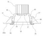
도 1은 본 발명에 따른 매립등의 분리 사시도이고, 도 2는 본 발명에 따른 매립등의 결합 단면도이며, 도 3은 본 발명에 따른 매립등의 분리 단면도이다.1 is an exploded perspective view of a buried light according to the present invention, Figure 2 is a combined cross-sectional view of a buried light according to the present invention, Figure 3 is an exploded cross-sectional view of a buried light according to the present invention.
도시와 같이 본 발명의 천정 매립등은, 열전도율이 우수한 방열체(10)와, 다수의 엘이디(21)(21')가 솔더링된 회로기판(20)과, 매립등을 천정에 고정하기 위한 스프링탄지구(31)(31')를 갖는 지지대(30)(30')과, 상기 지지대(30)(30')의 사이에 결합되는 원형틀체(40)와, 내측으로 투광판(50) 및 반사갓(60)이 삽입되는 내틀체(80)와, 천정 하부면으로 노출되어 실내를 향하는 장식외체(70)의 구성으로 이루어져 있는 것이다.As shown in the drawing, the ceiling buried light of the present invention includes a
상기의 방열체(10)는 알루미늄과 같이 열전도율이 우수한 재질을 이용하여 압출 성형 제작하는 것으로서, 수직방향으로 다수의 방열핀(11)(11')이 방사형 구조를 갖고 돌출되게끔 만들어지게 된다. 이러한 방열체(10)의 하측에는 상기 방열체(10)의 외경보다는 작은 외경으로 된 돌출부(12)를 형성하고 있다. 여기서, 상기의 돌출부(12)는 방열체(10)의 하부 외측을 절취하여 형성되도록 할 수도 있는 것 이고, 상기의 방열핀(11)(11')에 대하여 압출 형상을 통해 회로기판(20) 또는 지지대(30)(30')를 조립하기 위한 나사홈을 형성할 수도 있을 것이다.The
상기의 회로기판(20)에는 설치상태에서의 저면에 다수의 엘이디(21)(21')를 솔더링 형성한 것으로서, 상기의 엘이디(21)(21')는 설치 개수와 형태에 제한을 받지 않을 것이고, 발광색 역시 다양한 선택이 가능한 것이다.In the
상기의 지지대(30)(30')는 금속판재를 절곡 형성하여 된 것으로서, 천정매립등에서 널리 사용되는 일반적인 형태의 다양한 스프링탄지구(31)(31')를 고정하기 위한 목적과 동시에 방열체(10)와 원형틀체(40)를 이격 고정하기 위한 역할을 하는 것이다.The support (30, 30 ') is formed by bending the metal plate, and the purpose of fixing a variety of spring tanks (31, 31') of the general form widely used in the ceiling, etc. 10) and the
상기의 원형틀체(40)는 하부에 외향 확장형태의 플랜지부(41)가 형성되어 있고 상기의 플랜지부(41)에는 외측 개방형태의 삽입홈(42)이 다수 형성되어 있으며 삽입홈(42)의 일측에는 플랜지부(41)의 상부면으로부터 두께가 점차 얇아지도록 하는 형태의 경사면(43)이 형성되어 있는 것으로서, 상기의 경사면(43) 중 플랜지부(41)의 가장 얇은 두께를 형성하는 경사면의 시작부분은 상기 삽입홈(42)과 연결되도록 한 것이다.The
상기의 투광판(50)은 유백색의 합성수지 또는 유리재를 이용하여 원반 형태로 만들어진 것이다.The
상기의 반사갓(60)은 하향 확장 형태의 갓 모양을 갖고 있는 것으로서, 내면에는 크롬도금층과 같은 광택면을 형성하고, 하단 외측에는 돌출된 끼움부(61)가 형성되어 있으며 끼움부(61)의 상부면에는 밴딩을 통해 상향 돌출된 걸림턱(62)이 형성되어 있는 것이다.The
상기의 장식외체(70)는 합성수지 등을 이용하여 원형으로 제작하는 것인데, 상부 외측에는 내측 중심을 향하여 돌출된 계지구(71)가 장식외체(70)의 상부면으로부터 상향 이격된 상태로 형성되어 있는 것이다.The decorative
상기의 내틀체(80) 상부에는 수직의 안치홈(81)이 다수 형성되어 있고 안치홈(81)의 하부 일측으로는 절개홈 형태의 안내홈(82)이 형성되어 있는 것이다.A plurality of vertical
이에 따라, 상기 방열체(10)의 돌출부(12) 저면에 회로기판(20)을 밀착한 상태에서 별도의 나사못 등을 이용해 이들을 서로 긴밀하게 밀착 고정하면 되는 것이고, 상기 방열체(10)의 하부를 이용하여 양측으로 지지대(30)(30')의 선단을 결합하면 되는 것이며, 상기 지지대(30)(30')의 하단 사이에는 원형틀체(40)가 위치하도록 결합한다.Accordingly, in a state in which the
또한, 상기 원형틀체(40)의 내측에는 투광판(50)과 반사갓(60)이 순차적으로 적층 삽입된 상태의 내틀체(80)를 삽입하는 것이고, 이때의 반사갓(60)은 상부가 개방되어 있으면서도, 반사갓(60)의 상부 내측으로 회로기판(20)을 포함한 방열체(10)의 돌출부(12)가 삽입 위치할 수 있도록 하여 상기 회로기판(20) 상의 엘이디(21)(21')가 점등하는 경우 이와 같은 점등 빛이 외부로 유출되지 않고 온전하게 반사갓(60)을 통해 하측 실내를 비출 수 있게 한 것이다.In addition, the inner side of the
또한, 상기의 장식외체(70)를 원형틀체(40)의 하부면에 밀착 고정한 상태에서 상기의 천정 매립등을 고정 설치하게 되면 상기 장식외체(70)는 실내로 노출되어 고유의 색감이나 질감을 연출하게 될 것이고, 관통된 장식외체(70)의 중앙부분 을 통해 투광판(50)을 통과하는 엘이디(21)(21')의 점등 빛이 실내를 조명하게 되는 것이다.In addition, when the
이때, 상기의 원형틀체(40)와 장식외체(70) 간의 결합구조는 도 4의 도시와 같이 원형틀체(40)의 플랜지부(41)에 형성된 삽입홈(42)으로 장식외체(70)의 계지구(71)가 삽입되게 한 상태에서 원형틀체(40) 또는 장식외체(70)를 회전시키면 상기의 계지구(71)가 경사면(43)을 타고 이동하게 되는 것이고, 상기의 경사면(43)으로 인해 계지구(71)는 점차 두꺼워지는 플랜지부(41)를 향하게 되므로 결국 상기의 플랜지부(41)는 장식외체(70)와 계지구(71)의 사이에서 가압 고정되는 것이다.At this time, the coupling structure between the
이에 따라 상기의 원형틀체(40)와 장식외체(70)는 회전 작업만으로도 상호 간의 견고한 결합이 이루어질 수 있는 것이며, 이들을 서로 분리하고자 하는 경우에도 반대방향으로의 회전작업을 통해 능히 원활하게 분리시킬 수 있는 것이다. 특히, 상기의 삽입홈(42)과 계지구(71)는 평면상 3개소 내지는 4개소 정도로 분할 형성함에 따라 전체적으로 안정적인 결합 상태를 유지할 수 있도록 하는 것이 바람직하다.Accordingly, the
또한, 내틀체(80)와 투광판(50) 및 반사갓(60)의 결합구조는 도 5의 도시와 같이 내틀체(80)의 내부로 투광판(50)을 우선 삽입하여 안치시킨 상태에서 내틀체(80)의 안치홈(81)으로 반사갓(60)의 끼움부(61)가 위치되게 하여 이를 하향 안치시킨 상태에서, 상기 내틀체(80) 또는 반사갓(60)을 회전시키면 상기의 끼움부(61)가 안내홈(82)을 따라 이동하게 될 것인데, 상기의 끼움부(61)에는 안내홈(82)의 상,하폭과 동일하거나 미세하게 큰 높이를 갖고 돌출된 걸림턱(62)이 형 성되어 있으므로 상기의 걸림턱(62)과 끼움부(61)가 안내홈(82)의 내측에서 긴밀하게 가압 삽입됨에 따라 상호 간의 견고한 조립 상태가 이루어지게 된다.In addition, the coupling structure of the
특히, 상기의 내틀체(80)에 안치된 상태의 투광판(50)은 상기와 같이 반사갓(60)이 내틀체(80)에 결합 고정됨에 따라 자연스럽게 내틀체(80)와 반사갓(60)의 사이에서 동시에 위치 고정될 수 있는 구조를 갖게 된다.In particular, the
이에 따라 본 발명의 천정용 원형 매립등은, 조립과 설치가 매우 용이하면서도 엘이디로부터 발생하는 고온의 열기를 빠르게 방열시켜 줄 수 있어 사용 수명의 연장은 물론 소비전력을 감소시키는데에도 탁월한 작용을 하게 된다.As a result, the circular round landfill lamp of the present invention is very easy to assemble and install, and can quickly dissipate the high temperature heat generated from the LED, thereby extending the service life and reducing power consumption. .
이상과 같은 본 명세서에 기재된 실시예와 도면에 도시된 구성은 본 발명의 가장 바람직한 일실시예에 불과할 뿐이고 본 발명의 기술적 사상을 모두 대변하는 것은 아니므로, 이들을 대체할 수 있는 다양한 균등물과 변형 예들이 있을 수 있음을 이해하여야 한다.It is to be understood that both the foregoing general description and the following detailed description of the present invention are exemplary and explanatory and are intended to provide further explanation of the present invention as defined by the appended claims. Examples should be understood.
도 1은 본 발명에 따른 매립등의 분리 사시도1 is an exploded perspective view of a landfill lamp according to the present invention
도 2는 본 발명에 따른 매립등의 결합 단면도Figure 2 is a cross-sectional view of the combination of the buried light according to the present invention
도 3은 본 발명에 따른 매립등의 분리 단면도3 is an exploded cross-sectional view of a buried light according to the present invention
도 4는 본 발명에 따른 매립등의 요부 상세도4 is a detailed view of the main portion of the landfill, etc. according to the present invention
도 5는 본 발명에 따른 매립등의 또 다른 요부에 대한 상세도5 is a detailed view of still another main part of the landfill, etc. according to the present invention;
* 도면의 주요부분에 대한 부호의 설명 *Explanation of symbols on the main parts of the drawings
10 : 방열체11,11' : 방열핀10:
12 : 돌출부12: protrusion
20 : 회로기판21,21' : 엘이디20:
30,30' : 지지대31,31' : 스프링탄지구30,30 ': Supporting 31,31': Spring Tan District
40 : 원형틀체41 : 플랜지부40: circular frame 41: flange portion
42 : 삽입홈43 : 경사면42: insertion groove 43: inclined surface
50 : 투광판50: floodlight
60 : 반사갓61 : 끼움부60: reflection shade 61: fitting
62 : 걸림턱62: jamming jaw
70 : 장식외체71 : 계지구70: decorative exterior 71: gye district
80 : 내틀체81 : 안치홈80: inner frame 81: settled groove
82 : 안내홈82: Information Home
Claims (3)
Translated fromKoreanPriority Applications (1)
| Application Number | Priority Date | Filing Date | Title |
|---|---|---|---|
| KR1020090066322AKR101079269B1 (en) | 2009-07-21 | 2009-07-21 | Round down light using LED |
Applications Claiming Priority (1)
| Application Number | Priority Date | Filing Date | Title |
|---|---|---|---|
| KR1020090066322AKR101079269B1 (en) | 2009-07-21 | 2009-07-21 | Round down light using LED |
Publications (2)
| Publication Number | Publication Date |
|---|---|
| KR20110008796A KR20110008796A (en) | 2011-01-27 |
| KR101079269B1true KR101079269B1 (en) | 2011-11-03 |
Family
ID=43614752
Family Applications (1)
| Application Number | Title | Priority Date | Filing Date |
|---|---|---|---|
| KR1020090066322AExpired - Fee RelatedKR101079269B1 (en) | 2009-07-21 | 2009-07-21 | Round down light using LED |
Country Status (1)
| Country | Link |
|---|---|
| KR (1) | KR101079269B1 (en) |
Cited By (5)
| Publication number | Priority date | Publication date | Assignee | Title |
|---|---|---|---|---|
| KR101430731B1 (en)* | 2013-02-15 | 2014-08-14 | 후지라이테크 주식회사 | Led lighting apparatus |
| KR20150120056A (en)* | 2014-04-17 | 2015-10-27 | 주식회사 국민조명 | LED lighting device with an ext ernal radiation structure |
| KR101615703B1 (en) | 2014-01-29 | 2016-05-12 | 이영규 | Led lamp for improving heat radiation |
| RU189749U1 (en)* | 2019-04-08 | 2019-06-03 | Общество с ограниченной ответственностью "ЦЕНТРСВЕТ" | Ceiling Recessed Light |
| RU189779U1 (en)* | 2019-04-08 | 2019-06-04 | Общество с ограниченной ответственностью "Центрсвет". | CEILING BUILT-IN LAMP |
Families Citing this family (40)
| Publication number | Priority date | Publication date | Assignee | Title |
|---|---|---|---|---|
| KR200466480Y1 (en)* | 2011-02-25 | 2013-04-17 | 이효덕 | Insert type lamp for the ceiling |
| US8684569B2 (en) | 2011-07-06 | 2014-04-01 | Cree, Inc. | Lens and trim attachment structure for solid state downlights |
| US9599315B1 (en)* | 2012-01-19 | 2017-03-21 | Cooper Technologies Company | Optical attachment features for light-emitting diode-based lighting system |
| KR200469177Y1 (en)* | 2012-03-20 | 2013-09-25 | 박상희 | Reclamation light's fixing clamp |
| KR101248155B1 (en)* | 2012-04-17 | 2013-04-03 | (주)알텍테크놀로지스 | Embedded Lighting |
| US10591120B2 (en) | 2015-05-29 | 2020-03-17 | DMF, Inc. | Lighting module for recessed lighting systems |
| US10753558B2 (en) | 2013-07-05 | 2020-08-25 | DMF, Inc. | Lighting apparatus and methods |
| US11435064B1 (en) | 2013-07-05 | 2022-09-06 | DMF, Inc. | Integrated lighting module |
| US10139059B2 (en) | 2014-02-18 | 2018-11-27 | DMF, Inc. | Adjustable compact recessed lighting assembly with hangar bars |
| US10563850B2 (en) | 2015-04-22 | 2020-02-18 | DMF, Inc. | Outer casing for a recessed lighting fixture |
| US11060705B1 (en) | 2013-07-05 | 2021-07-13 | DMF, Inc. | Compact lighting apparatus with AC to DC converter and integrated electrical connector |
| US9964266B2 (en) | 2013-07-05 | 2018-05-08 | DMF, Inc. | Unified driver and light source assembly for recessed lighting |
| US10551044B2 (en) | 2015-11-16 | 2020-02-04 | DMF, Inc. | Recessed lighting assembly |
| US11255497B2 (en) | 2013-07-05 | 2022-02-22 | DMF, Inc. | Adjustable electrical apparatus with hangar bars for installation in a building |
| USD851046S1 (en) | 2015-10-05 | 2019-06-11 | DMF, Inc. | Electrical Junction Box |
| KR102459100B1 (en)* | 2016-01-15 | 2022-10-27 | 쑤저우 레킨 세미컨덕터 컴퍼니 리미티드 | Light emitting package and lighting device having thereof |
| WO2018237294A2 (en) | 2017-06-22 | 2018-12-27 | DMF, Inc. | THIN-PROFILE SURFACE MOUNTING LIGHTING DEVICE |
| US10488000B2 (en) | 2017-06-22 | 2019-11-26 | DMF, Inc. | Thin profile surface mount lighting apparatus |
| USD905327S1 (en) | 2018-05-17 | 2020-12-15 | DMF, Inc. | Light fixture |
| US11067231B2 (en) | 2017-08-28 | 2021-07-20 | DMF, Inc. | Alternate junction box and arrangement for lighting apparatus |
| CA3083359A1 (en) | 2017-11-28 | 2019-06-06 | DMF, Inc. | Adjustable hanger bar assembly |
| CA3087187A1 (en) | 2017-12-27 | 2019-07-04 | DMF, Inc. | Methods and apparatus for adjusting a luminaire |
| USD877957S1 (en) | 2018-05-24 | 2020-03-10 | DMF Inc. | Light fixture |
| WO2019241198A1 (en) | 2018-06-11 | 2019-12-19 | DMF, Inc. | A polymer housing for a recessed lighting system and methods for using same |
| USD903605S1 (en) | 2018-06-12 | 2020-12-01 | DMF, Inc. | Plastic deep electrical junction box |
| WO2020072592A1 (en) | 2018-10-02 | 2020-04-09 | Ver Lighting Llc | A bar hanger assembly with mating telescoping bars |
| USD901398S1 (en) | 2019-01-29 | 2020-11-10 | DMF, Inc. | Plastic deep electrical junction box |
| USD1012864S1 (en) | 2019-01-29 | 2024-01-30 | DMF, Inc. | Portion of a plastic deep electrical junction box |
| USD864877S1 (en) | 2019-01-29 | 2019-10-29 | DMF, Inc. | Plastic deep electrical junction box with a lighting module mounting yoke |
| USD966877S1 (en) | 2019-03-14 | 2022-10-18 | Ver Lighting Llc | Hanger bar for a hanger bar assembly |
| WO2021051101A1 (en) | 2019-09-12 | 2021-03-18 | DMF, Inc. | Miniature lighting module and lighting fixtures using same |
| KR102359785B1 (en)* | 2019-11-18 | 2022-02-09 | 박병기 | Lighting Device |
| CN111623280A (en)* | 2020-06-10 | 2020-09-04 | 张蓓 | LED down lamp with built-in lightning protection structure |
| CA3124969A1 (en) | 2020-07-16 | 2022-01-16 | DMF, Inc. | Round metal housing for a lighting system |
| CA3124987A1 (en) | 2020-07-17 | 2022-01-17 | DMF, Inc. | Bar hanger assembly with crossmembers and housing assemblies using same |
| USD990030S1 (en) | 2020-07-17 | 2023-06-20 | DMF, Inc. | Housing for a lighting system |
| CA3124976A1 (en) | 2020-07-17 | 2022-01-17 | DMF, Inc. | Polymer housing for a lighting system and methods for using same |
| US11585517B2 (en) | 2020-07-23 | 2023-02-21 | DMF, Inc. | Lighting module having field-replaceable optics, improved cooling, and tool-less mounting features |
| GB2599076B (en)* | 2020-09-08 | 2025-07-23 | Iq Structures Sro | Modular luminaires |
| KR102785661B1 (en)* | 2024-11-28 | 2025-03-25 | 주식회사 올라이팅 | LED lighting apparatus for ceiling |
- 2009
- 2009-07-21KRKR1020090066322Apatent/KR101079269B1/ennot_activeExpired - Fee Related
Cited By (6)
| Publication number | Priority date | Publication date | Assignee | Title |
|---|---|---|---|---|
| KR101430731B1 (en)* | 2013-02-15 | 2014-08-14 | 후지라이테크 주식회사 | Led lighting apparatus |
| KR101615703B1 (en) | 2014-01-29 | 2016-05-12 | 이영규 | Led lamp for improving heat radiation |
| KR20150120056A (en)* | 2014-04-17 | 2015-10-27 | 주식회사 국민조명 | LED lighting device with an ext ernal radiation structure |
| KR101596362B1 (en) | 2014-04-17 | 2016-02-22 | 주식회사 국민조명 | LED lighting device with an ext ernal radiation structure |
| RU189749U1 (en)* | 2019-04-08 | 2019-06-03 | Общество с ограниченной ответственностью "ЦЕНТРСВЕТ" | Ceiling Recessed Light |
| RU189779U1 (en)* | 2019-04-08 | 2019-06-04 | Общество с ограниченной ответственностью "Центрсвет". | CEILING BUILT-IN LAMP |
Also Published As
| Publication number | Publication date |
|---|---|
| KR20110008796A (en) | 2011-01-27 |
Similar Documents
| Publication | Publication Date | Title |
|---|---|---|
| KR101079269B1 (en) | Round down light using LED | |
| US9857069B2 (en) | Spherical lamp with easy heat dissipation | |
| DK2378193T3 (en) | Lighting apparatus utilizing light emitting diode | |
| EP2390555A1 (en) | Illuminating apparatus | |
| US20130170210A1 (en) | Led fixture with heat pipe | |
| KR101079279B1 (en) | Round down light using LED | |
| KR20110101789A (en) | Lighting cover with air pipe and LED lighting device using same | |
| JP2009266780A (en) | Luminous body and luminaire | |
| JP2009009826A (en) | Lighting device | |
| KR100908578B1 (en) | LED module for electric vehicle lighting and LED lamp for electric vehicle | |
| CN102287727A (en) | LED (light emitting diode) down lamp and lamp body thereof | |
| US8556458B2 (en) | Power source unit and illumination device | |
| KR101102455B1 (en) | LED lighting fixtures | |
| CN201344429Y (en) | A LED ceiling lamp | |
| KR101136048B1 (en) | Led ceiling downlingt with effective heat dissipation | |
| US8789976B2 (en) | Integrated multi-layered illuminating unit and integrated multi-layered illuminating assembling unit | |
| JP2012124109A (en) | Cover member mounting device, base-attached lamp, and lighting fixture | |
| KR101826260B1 (en) | Advanced LED lamp apparatus | |
| KR100933630B1 (en) | Lighting fixture using light emitting diode | |
| KR101083034B1 (en) | Luminaire | |
| KR20110034259A (en) | LED lighting structure | |
| KR20220168796A (en) | Condensation improvement lighting fixtures | |
| KR20120007312U (en) | Multicolor interior light using LED | |
| KR101091577B1 (en) | LED luminaires with improved coverage and heat dissipation | |
| KR101042274B1 (en) | Prefabricated LED luminaire with excellent heat dissipation and light diffusion |
Legal Events
| Date | Code | Title | Description |
|---|---|---|---|
| A201 | Request for examination | ||
| PA0109 | Patent application | St.27 status event code:A-0-1-A10-A12-nap-PA0109 | |
| PA0201 | Request for examination | St.27 status event code:A-1-2-D10-D11-exm-PA0201 | |
| R18-X000 | Changes to party contact information recorded | St.27 status event code:A-3-3-R10-R18-oth-X000 | |
| PG1501 | Laying open of application | St.27 status event code:A-1-1-Q10-Q12-nap-PG1501 | |
| E902 | Notification of reason for refusal | ||
| PE0902 | Notice of grounds for rejection | St.27 status event code:A-1-2-D10-D21-exm-PE0902 | |
| E13-X000 | Pre-grant limitation requested | St.27 status event code:A-2-3-E10-E13-lim-X000 | |
| P11-X000 | Amendment of application requested | St.27 status event code:A-2-2-P10-P11-nap-X000 | |
| P13-X000 | Application amended | St.27 status event code:A-2-2-P10-P13-nap-X000 | |
| E701 | Decision to grant or registration of patent right | ||
| PE0701 | Decision of registration | St.27 status event code:A-1-2-D10-D22-exm-PE0701 | |
| GRNT | Written decision to grant | ||
| PR0701 | Registration of establishment | St.27 status event code:A-2-4-F10-F11-exm-PR0701 | |
| PR1002 | Payment of registration fee | St.27 status event code:A-2-2-U10-U11-oth-PR1002 Fee payment year number:1 | |
| PG1601 | Publication of registration | St.27 status event code:A-4-4-Q10-Q13-nap-PG1601 | |
| FPAY | Annual fee payment | Payment date:20141121 Year of fee payment:4 | |
| PR1001 | Payment of annual fee | St.27 status event code:A-4-4-U10-U11-oth-PR1001 Fee payment year number:4 | |
| LAPS | Lapse due to unpaid annual fee | ||
| PC1903 | Unpaid annual fee | St.27 status event code:A-4-4-U10-U13-oth-PC1903 Not in force date:20151028 Payment event data comment text:Termination Category : DEFAULT_OF_REGISTRATION_FEE | |
| P22-X000 | Classification modified | St.27 status event code:A-4-4-P10-P22-nap-X000 | |
| PC1903 | Unpaid annual fee | St.27 status event code:N-4-6-H10-H13-oth-PC1903 Ip right cessation event data comment text:Termination Category : DEFAULT_OF_REGISTRATION_FEE Not in force date:20151028 | |
| R18-X000 | Changes to party contact information recorded | St.27 status event code:A-5-5-R10-R18-oth-X000 | |
| P22-X000 | Classification modified | St.27 status event code:A-4-4-P10-P22-nap-X000 |