KR101073035B1 - H Side-branch Stent - Google Patents
H Side-branch StentDownload PDFInfo
- Publication number
- KR101073035B1 KR101073035B1KR1020090041769AKR20090041769AKR101073035B1KR 101073035 B1KR101073035 B1KR 101073035B1KR 1020090041769 AKR1020090041769 AKR 1020090041769AKR 20090041769 AKR20090041769 AKR 20090041769AKR 101073035 B1KR101073035 B1KR 101073035B1
- Authority
- KR
- South Korea
- Prior art keywords
- stent
- side branch
- blood vessel
- bridge
- vessels
- Prior art date
- Legal status (The legal status is an assumption and is not a legal conclusion. Google has not performed a legal analysis and makes no representation as to the accuracy of the status listed.)
- Expired - Fee Related
Links
Images


Classifications
- A—HUMAN NECESSITIES
- A61—MEDICAL OR VETERINARY SCIENCE; HYGIENE
- A61F—FILTERS IMPLANTABLE INTO BLOOD VESSELS; PROSTHESES; DEVICES PROVIDING PATENCY TO, OR PREVENTING COLLAPSING OF, TUBULAR STRUCTURES OF THE BODY, e.g. STENTS; ORTHOPAEDIC, NURSING OR CONTRACEPTIVE DEVICES; FOMENTATION; TREATMENT OR PROTECTION OF EYES OR EARS; BANDAGES, DRESSINGS OR ABSORBENT PADS; FIRST-AID KITS
- A61F2/00—Filters implantable into blood vessels; Prostheses, i.e. artificial substitutes or replacements for parts of the body; Appliances for connecting them with the body; Devices providing patency to, or preventing collapsing of, tubular structures of the body, e.g. stents
- A61F2/82—Devices providing patency to, or preventing collapsing of, tubular structures of the body, e.g. stents
- A61F2/856—Single tubular stent with a side portal passage
- A—HUMAN NECESSITIES
- A61—MEDICAL OR VETERINARY SCIENCE; HYGIENE
- A61F—FILTERS IMPLANTABLE INTO BLOOD VESSELS; PROSTHESES; DEVICES PROVIDING PATENCY TO, OR PREVENTING COLLAPSING OF, TUBULAR STRUCTURES OF THE BODY, e.g. STENTS; ORTHOPAEDIC, NURSING OR CONTRACEPTIVE DEVICES; FOMENTATION; TREATMENT OR PROTECTION OF EYES OR EARS; BANDAGES, DRESSINGS OR ABSORBENT PADS; FIRST-AID KITS
- A61F2/00—Filters implantable into blood vessels; Prostheses, i.e. artificial substitutes or replacements for parts of the body; Appliances for connecting them with the body; Devices providing patency to, or preventing collapsing of, tubular structures of the body, e.g. stents
- A61F2/02—Prostheses implantable into the body
- A61F2/04—Hollow or tubular parts of organs, e.g. bladders, tracheae, bronchi or bile ducts
- A61F2/06—Blood vessels
- A61F2/07—Stent-grafts
- A—HUMAN NECESSITIES
- A61—MEDICAL OR VETERINARY SCIENCE; HYGIENE
- A61F—FILTERS IMPLANTABLE INTO BLOOD VESSELS; PROSTHESES; DEVICES PROVIDING PATENCY TO, OR PREVENTING COLLAPSING OF, TUBULAR STRUCTURES OF THE BODY, e.g. STENTS; ORTHOPAEDIC, NURSING OR CONTRACEPTIVE DEVICES; FOMENTATION; TREATMENT OR PROTECTION OF EYES OR EARS; BANDAGES, DRESSINGS OR ABSORBENT PADS; FIRST-AID KITS
- A61F2/00—Filters implantable into blood vessels; Prostheses, i.e. artificial substitutes or replacements for parts of the body; Appliances for connecting them with the body; Devices providing patency to, or preventing collapsing of, tubular structures of the body, e.g. stents
- A61F2/82—Devices providing patency to, or preventing collapsing of, tubular structures of the body, e.g. stents
- A—HUMAN NECESSITIES
- A61—MEDICAL OR VETERINARY SCIENCE; HYGIENE
- A61F—FILTERS IMPLANTABLE INTO BLOOD VESSELS; PROSTHESES; DEVICES PROVIDING PATENCY TO, OR PREVENTING COLLAPSING OF, TUBULAR STRUCTURES OF THE BODY, e.g. STENTS; ORTHOPAEDIC, NURSING OR CONTRACEPTIVE DEVICES; FOMENTATION; TREATMENT OR PROTECTION OF EYES OR EARS; BANDAGES, DRESSINGS OR ABSORBENT PADS; FIRST-AID KITS
- A61F2/00—Filters implantable into blood vessels; Prostheses, i.e. artificial substitutes or replacements for parts of the body; Appliances for connecting them with the body; Devices providing patency to, or preventing collapsing of, tubular structures of the body, e.g. stents
- A61F2/95—Instruments specially adapted for placement or removal of stents or stent-grafts
- A61F2/954—Instruments specially adapted for placement or removal of stents or stent-grafts for placing stents or stent-grafts in a bifurcation
- A—HUMAN NECESSITIES
- A61—MEDICAL OR VETERINARY SCIENCE; HYGIENE
- A61F—FILTERS IMPLANTABLE INTO BLOOD VESSELS; PROSTHESES; DEVICES PROVIDING PATENCY TO, OR PREVENTING COLLAPSING OF, TUBULAR STRUCTURES OF THE BODY, e.g. STENTS; ORTHOPAEDIC, NURSING OR CONTRACEPTIVE DEVICES; FOMENTATION; TREATMENT OR PROTECTION OF EYES OR EARS; BANDAGES, DRESSINGS OR ABSORBENT PADS; FIRST-AID KITS
- A61F2/00—Filters implantable into blood vessels; Prostheses, i.e. artificial substitutes or replacements for parts of the body; Appliances for connecting them with the body; Devices providing patency to, or preventing collapsing of, tubular structures of the body, e.g. stents
- A61F2/95—Instruments specially adapted for placement or removal of stents or stent-grafts
- A61F2/958—Inflatable balloons for placing stents or stent-grafts
- A—HUMAN NECESSITIES
- A61—MEDICAL OR VETERINARY SCIENCE; HYGIENE
- A61L—METHODS OR APPARATUS FOR STERILISING MATERIALS OR OBJECTS IN GENERAL; DISINFECTION, STERILISATION OR DEODORISATION OF AIR; CHEMICAL ASPECTS OF BANDAGES, DRESSINGS, ABSORBENT PADS OR SURGICAL ARTICLES; MATERIALS FOR BANDAGES, DRESSINGS, ABSORBENT PADS OR SURGICAL ARTICLES
- A61L27/00—Materials for grafts or prostheses or for coating grafts or prostheses
- A61L27/02—Inorganic materials
- A61L27/04—Metals or alloys
- A—HUMAN NECESSITIES
- A61—MEDICAL OR VETERINARY SCIENCE; HYGIENE
- A61L—METHODS OR APPARATUS FOR STERILISING MATERIALS OR OBJECTS IN GENERAL; DISINFECTION, STERILISATION OR DEODORISATION OF AIR; CHEMICAL ASPECTS OF BANDAGES, DRESSINGS, ABSORBENT PADS OR SURGICAL ARTICLES; MATERIALS FOR BANDAGES, DRESSINGS, ABSORBENT PADS OR SURGICAL ARTICLES
- A61L27/00—Materials for grafts or prostheses or for coating grafts or prostheses
- A61L27/50—Materials characterised by their function or physical properties, e.g. injectable or lubricating compositions, shape-memory materials, surface modified materials
- A61L27/54—Biologically active materials, e.g. therapeutic substances
- A—HUMAN NECESSITIES
- A61—MEDICAL OR VETERINARY SCIENCE; HYGIENE
- A61F—FILTERS IMPLANTABLE INTO BLOOD VESSELS; PROSTHESES; DEVICES PROVIDING PATENCY TO, OR PREVENTING COLLAPSING OF, TUBULAR STRUCTURES OF THE BODY, e.g. STENTS; ORTHOPAEDIC, NURSING OR CONTRACEPTIVE DEVICES; FOMENTATION; TREATMENT OR PROTECTION OF EYES OR EARS; BANDAGES, DRESSINGS OR ABSORBENT PADS; FIRST-AID KITS
- A61F2/00—Filters implantable into blood vessels; Prostheses, i.e. artificial substitutes or replacements for parts of the body; Appliances for connecting them with the body; Devices providing patency to, or preventing collapsing of, tubular structures of the body, e.g. stents
- A61F2/02—Prostheses implantable into the body
- A61F2/04—Hollow or tubular parts of organs, e.g. bladders, tracheae, bronchi or bile ducts
- A61F2/06—Blood vessels
- A61F2002/065—Y-shaped blood vessels
- A61F2002/067—Y-shaped blood vessels modular
- A—HUMAN NECESSITIES
- A61—MEDICAL OR VETERINARY SCIENCE; HYGIENE
- A61F—FILTERS IMPLANTABLE INTO BLOOD VESSELS; PROSTHESES; DEVICES PROVIDING PATENCY TO, OR PREVENTING COLLAPSING OF, TUBULAR STRUCTURES OF THE BODY, e.g. STENTS; ORTHOPAEDIC, NURSING OR CONTRACEPTIVE DEVICES; FOMENTATION; TREATMENT OR PROTECTION OF EYES OR EARS; BANDAGES, DRESSINGS OR ABSORBENT PADS; FIRST-AID KITS
- A61F2/00—Filters implantable into blood vessels; Prostheses, i.e. artificial substitutes or replacements for parts of the body; Appliances for connecting them with the body; Devices providing patency to, or preventing collapsing of, tubular structures of the body, e.g. stents
- A61F2/82—Devices providing patency to, or preventing collapsing of, tubular structures of the body, e.g. stents
- A61F2002/821—Ostial stents
- A—HUMAN NECESSITIES
- A61—MEDICAL OR VETERINARY SCIENCE; HYGIENE
- A61F—FILTERS IMPLANTABLE INTO BLOOD VESSELS; PROSTHESES; DEVICES PROVIDING PATENCY TO, OR PREVENTING COLLAPSING OF, TUBULAR STRUCTURES OF THE BODY, e.g. STENTS; ORTHOPAEDIC, NURSING OR CONTRACEPTIVE DEVICES; FOMENTATION; TREATMENT OR PROTECTION OF EYES OR EARS; BANDAGES, DRESSINGS OR ABSORBENT PADS; FIRST-AID KITS
- A61F2/00—Filters implantable into blood vessels; Prostheses, i.e. artificial substitutes or replacements for parts of the body; Appliances for connecting them with the body; Devices providing patency to, or preventing collapsing of, tubular structures of the body, e.g. stents
- A61F2/82—Devices providing patency to, or preventing collapsing of, tubular structures of the body, e.g. stents
- A61F2002/828—Means for connecting a plurality of stents allowing flexibility of the whole structure
Landscapes
- Health & Medical Sciences (AREA)
- Biomedical Technology (AREA)
- Engineering & Computer Science (AREA)
- Life Sciences & Earth Sciences (AREA)
- Transplantation (AREA)
- Oral & Maxillofacial Surgery (AREA)
- Animal Behavior & Ethology (AREA)
- General Health & Medical Sciences (AREA)
- Public Health (AREA)
- Veterinary Medicine (AREA)
- Vascular Medicine (AREA)
- Heart & Thoracic Surgery (AREA)
- Cardiology (AREA)
- Chemical & Material Sciences (AREA)
- Medicinal Chemistry (AREA)
- Epidemiology (AREA)
- Dermatology (AREA)
- Pulmonology (AREA)
- Gastroenterology & Hepatology (AREA)
- Molecular Biology (AREA)
- Inorganic Chemistry (AREA)
- Media Introduction/Drainage Providing Device (AREA)
- Prostheses (AREA)
Abstract
Translated fromKoreanDescription
Translated fromKorean본 발명은 H 사이드 브랜치 혈관용 스텐트에 관한 것으로서, 보다 구체적으로 스텐트가 분지혈관 개구부의 내주면을 원주방향을 따라 완전히 지지하여, 분지혈관 개구부의 재협착을 방지할 수 있고, 주혈관과 분지혈관의 경계부에 스텐트가 밀집되거나, 주혈관 내에 스텐트의 일부 영역이 돌출되지 않으므로 혈류 장애를 발생시키지 않으며, 스텐트가 주혈관의 내벽에 간극 없이 완전히 밀착될 수 있는 H 사이드 브랜치 혈관용 스텐트에 관한 것이다.The present invention relates to an H side branch vascular stent, and more specifically, the stent fully supports the inner circumferential surface of the branch blood vessel opening along the circumferential direction, thereby preventing restenosis of the branch blood vessel opening, and It is related to the stent for H side branch blood vessels that do not cause a blood flow disorder because the stent is not concentrated or protrudes a part of the stent in the main vessel, and the stent can be completely adhered to the inner wall of the main vessel without gaps.
일반적으로 스텐트(stent)는 인체 내에서 발행하는 각 종 질병에 의해 인체 내의 내강이 좁아져서 그 고유의 기능을 저하시키거나, 혈관이 좁아져서 혈액 순환이 불량한 경우 등의 질환이 발생한 경우에 그 내강 또는 혈관의 내부에 시술되어 내강 또는 혈관을 확장시키는 의료용 기구이다.In general, stents are narrowed by the various diseases issued in the human body, and the lumen in the human body is narrowed, which lowers its own function, or when the disease occurs, such as when blood vessels are narrowed and poor blood circulation occurs. Or it is a medical instrument that is performed inside the blood vessels to expand the lumen or blood vessels.
관상동맥질환(coronary artery disease) 또는 허혈성 심장 질환(ischemic heart disease)은 관상동맥 혈관벽에 지방성분이 침착되고, 이에 동반된 염증반응 으로 관상동맥의 내강(lumen)이 점점 좁아지며, 좁아진 관상동맥의 내강 크기 때문에 심장 근육(심근)으로 충분한 혈액 공급이 이루어 지지 않아서 발생하는 질환이다.Coronary artery disease or ischemic heart disease is characterized by the deposition of fat on the walls of the coronary vessels and the accompanying inflammatory response, resulting in a narrowing of the lumen of the coronary arteries and the narrowing of the coronary arteries. Due to the size of the lumen, the heart muscle (myocardium) does not provide sufficient blood supply.
심근으로 충분한 혈액 공급되지 않으면 그 정도에 따라 흉통, 호흡 곤란 및 기타 증상이 발생한다. 이러한 관상동맥 질환은 협심증, 급성심근경색증 및 급사 등의 임상증상으로 나타난다.Without enough blood supply to the myocardium, chest pain, shortness of breath and other symptoms occur depending on the extent of this. Coronary artery disease is manifested in clinical symptoms such as angina pectoris, acute myocardial infarction and sudden death.
경피적 관상동맥 중재술(percutaneous coronary intervention: PCI)은 콜레스테롤이 혈관 벽에 침착되어 좁아진 관상동맥의 내강을 풍선 카테터(balloon catheter) 또는 스텐트를 이용하여 물리적으로 확장시키는 치료 방법이다. 하지만, 풍선 카테터를 이용한 경피적 관상동맥 확장술은 급성 폐쇄(acute closure) 또는 혈관 박리(dissection)와 같은 대표적인 합병증을 유발할 수 있다.Percutaneous coronary intervention (PCI) is a treatment method that physically expands the lumen of a narrowed coronary artery by using a balloon catheter or stent, where cholesterol is deposited on the vessel wall. However, percutaneous coronary angioplasty with balloon catheter can cause representative complications such as acute closure or vascular dissection.
한편, 스텐트를 이용한 치료법은 풍선 카테터를 이용한 치료법에 의해 유발될 수 있는 급성 폐쇄 및 혈관 박리를 방지할 수 있으나, 관상동맥 분지부 병변의 경우에는 이러한 스텐트 시술이 혈관의 재협착 감소에 기여하지 못하고 있는 실정이다.On the other hand, treatment with stents can prevent acute obstruction and vascular detachment that can be caused by balloon catheterization. However, in the case of coronary branch lesions, such stents do not contribute to the reduction of restenosis of blood vessels. There is a situation.
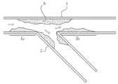
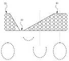
도 1은 관상동맥 분지부 병변(B)을 나타내는 개념도로서, 주혈관(1)의 근위부(1a)와 원위부(1b) 및 분지혈관(2)의 경계부에 협착이 발생된 경우를 도시한 것이다.Fig. 1 is a conceptual diagram showing coronary branching lesions (B), showing a case where stenosis occurs at the boundary between the proximal portion 1a, the
협착 소견을 나타내는 분지 혈관(2) 개구부의 치료를 위해서는 분지 혈관(2) 개구부의 내주면이 원주방향을 따라 약물 방출 스텐트에 의해 확실하게 지지되도록 위치되어야 한다.For the treatment of branching
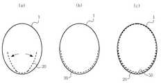
도 2 및 도 3은 종래 관상동맥 분지부 병변에 사용되는 스텐트의 시술 상태를 나타내는 개념도로서, 도 2는 스텐트(S)가 분지혈관(2)의 개구부를 완전히 둘러싸지 못하여, 분지 혈관(2) 내주면의 일부영역에만 위치된 상태를 도시한 것이고, 도 3은 스텐트(S)가 분지혈관(2)의 개구부를 완전히 둘러싸지만, 주혈관(1) 내의 공간으로 스텐트의 일부영역(C)이 돌출되어 배치된 상태를 도시한 것이다.2 and 3 is a conceptual diagram showing a state of the stent used in the conventional coronary branch lesions, Figure 2 is a stent (S) does not completely surround the opening of the
도 2에 도시된 바와 같이 스텐트(S)가 시술되면, 분지 혈관(2) 개구부의 내주면을 완전히 둘러싸지 못하는 영역(E)이 발생하게 되므로, 치료효과를 거둘 수 없는 문제점이 있고, 도 3에 도시된 바와 같이 스텐트(S)가 시술되면, 주혈관(1) 내에 위치된 스텐트(S)의 일부 영역(C) 때문에 혈류에 장애가 발생하는 문제점이 있다.As shown in FIG. 2, when the stent S is treated, a region E that does not completely surround the inner circumferential surface of the opening of the
본 발명은 상기와 같은 문제점을 해결하기 위한 것으로, 본 발명의 목적은 스텐트가 분지혈관 개구부의 내주면을 원주방향을 따라 완전히 지지하여, 분지혈관 개구부의 재협착을 방지할 수 있고, 스텐트가 주혈관과 분지혈관의 경계부에 밀집되거나, 주혈관 내에 스텐트의 일부 영역이 돌출되지 않으므로 혈류 장애를 발생시키지 않으며, 스텐트가 주혈관의 내벽에 간극 없이 완전히 밀착될 수 있는 H 사이드브랜치 혈관용 스텐트를 제공하는 것이다.The present invention is to solve the above problems, an object of the present invention is that the stent fully supports the inner circumferential surface of the branched blood vessel opening along the circumferential direction, can prevent the restenosis of the branched blood vessel opening, the stent is the main blood vessel It is not concentrated at the boundary of the hyperbranched or branched blood vessels, and some areas of the stent do not protrude in the main blood vessel, and thus does not cause blood flow disorder, and provides a stent for H side branch blood vessel which can fully adhere to the inner wall of the main blood vessel without gaps. will be.
또한, 본 발명의 목적은 종래의 통상적인 경피적 관상동맥 중재술과 동일하거나 유사한 방법으로 환자를 치료할 수 있으므로, 새로운 시술법에 따른 부담이 없는 H 사이드브랜치 혈관용 스텐트를 제공하는 것이다.It is also an object of the present invention to provide a method for treating a patient in the same or similar manner as conventional conventional percutaneous coronary intervention, thereby providing a stent for H side branch vascular without the burden of the new procedure.
본 발명의 상기한 목적을 달성하기 위하여,In order to achieve the above object of the present invention,
본 발명의 일 측면에 따르면,According to one aspect of the invention,
복수의 셀을 갖고, 중공 원통형의 제 1 스텐트;A first stent having a plurality of cells and having a hollow cylindrical shape;
상기 제 1 스텐트의 말단에 일 종단이 연결된 하나 이상의 브릿지; 및At least one bridge having one end connected to an end of the first stent; And
선단에 상기 브릿지의 타 종단이 연결되고, 복수의 셀을 갖고, 중공 원통형의의 제 2 스텐트를 포함하는 H 사이드 브랜치 혈관용 스텐트가 제공된다.The other end of the bridge is connected to the tip, has a plurality of cells, and is provided for the stent for H side branch blood vessel comprising a hollow cylindrical second stent.
본 발명의 또 다른 측면에 따르면,According to another aspect of the invention,
복수의 셀을 갖고, 상단부에 길이방향을 따라 선형 절개부가 형성되며, 팽창 가능한 중공 원통형의 제 1 스텐트;A first hollow stent having a plurality of cells and having a linear incision in a longitudinal direction at an upper end thereof, the inflatable hollow cylindrical;
상기 제 1 스텐트의 말단에 일 종단이 연결된 하나 이상의 브릿지; 및At least one bridge having one end connected to an end of the first stent; And
선단에 상기 브릿지의 타 종단이 연결되고, 복수의 셀을 갖고, 중공 원통형의 제 2 스텐트를 포함하는 H 사이드 브랜치 혈관용 스텐트가 제공된다.The other end of the bridge is connected to the front end, there is provided a stent for the H side branch vessel having a plurality of cells, including a hollow cylindrical second stent.
본 발명의 또 다른 측면에 따르면,According to another aspect of the invention,
복수의 셀을 갖고, 약물이 코팅되며, 중공 원통형의 제 1 스텐트;A first stent having a plurality of cells, coated with a drug, and having a hollow cylindrical shape;
상기 제 1 스텐트의 말단에 일 종단이 연결된 하나 이상의 브릿지; 및At least one bridge having one end connected to an end of the first stent; And
선단에 상기 브릿지의 타 종단이 연결되고, 복수의 셀을 갖고, 약물의 코팅되며, 중공 원통형의 제 2 스텐트를 포함하는 H 사이드 브랜치 혈관용 스텐트가 제공된다.The other end of the bridge is connected at the tip, has a plurality of cells, is coated with the drug, and is provided for the stent for H side branch vessels comprising a hollow cylindrical second stent.
이상에서 살펴본 바와 같이, 본 발명에 따른 H 사이드 브랜치 혈관용 스텐트는 분지혈관 개구부의 내주면을 원주방향을 따라 완전히 지지하여, 분지혈관 개구부의 재협착을 방지할 수 있고, 스텐트가 주혈관과 분지혈관의 경계부에 밀집되거나, 주혈관 내에 스텐트의 일부 영역이 돌출되지 않으므로 혈류 장애를 발생시키지 않으며, 스텐트가 주혈관의 내벽에 간극 없이 완전히 밀착될 수 있다.As described above, the H side branch vascular stent according to the present invention completely supports the inner circumferential surface of the branched blood vessel opening along the circumferential direction, thereby preventing restenosis of the branched blood vessel opening, and the stent has main and branched blood vessels. It is not crowded at the boundary of or the protruding part of the stent in the main blood vessel does not cause blood flow disorder, and the stent can be completely adhered to the inner wall of the main blood vessel without a gap.
또한, 본 발명에 따른 H 사이드 브랜치 혈관용 스텐트는 종래의 통상적인 경피적 관상동맥 중재술과 동일하거나 유사한 방법으로 환자를 치료할 수 있으므로, 새로운 시술법에 따른 부담을 발생시키지 않는다.In addition, the H side branch vascular stent according to the present invention can treat a patient in the same or similar manner as conventional conventional percutaneous coronary intervention, and thus does not incur the burden of the new procedure.
이하, 본 발명의 일 실시예에 따른 H 사이드 브랜치 혈관용 스텐트를 첨부된 도면을 참고하여 상세히 설명한다. 첨부된 도면은 본 발명의 예시적인 형태를 도시한 것으로, 이는 본 발명을 보다 상세히 설명하기 위해 제공되는 것일 뿐, 이에 의해 본 발명의 기술적인 범위가 한정되는 것은 아니며, 설명의 편의를 위하여 일부 구성요소의 크기 및 두께는 과장되거나 축소 도시될 수 있다.Hereinafter, with reference to the accompanying drawings the stent for H side branch vessels according to an embodiment of the present invention will be described in detail. The accompanying drawings show exemplary embodiments of the present invention, which are provided to explain the present invention in more detail, and thus the technical scope of the present invention is not limited thereto. The size and thickness of the elements may be exaggerated or reduced.
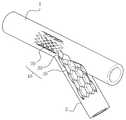
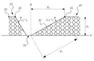
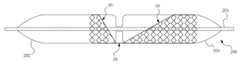
도 4는 본 발명의 일 실시예에 따른 H 사이드 브랜치 혈관용 스텐트를 나타내는 사시도이고, 도 5는 도 4에 도시된 H 사이드 브랜치 혈관용 스텐트를 펼친 상태의 상세 평면도이며, 도 6은 본 발명의 일 실시예에 따른 H 사이드 브랜치 혈관용 스텐트를 나타내는 요부 측면도이고, 도 7은 도 4에 도시된 H 사이드 브랜치 혈관용 스텐트가 시술된 상태의 단면도이다.4 is a perspective view showing the stent for H side branch blood vessel according to an embodiment of the present invention, Figure 5 is a detailed plan view of the unfolded state of the stent for H side branch blood vessel shown in Figure 4, Figure 6 is a view of the present invention FIG. 7 is a side view illustrating a main portion of the H side branch blood vessel stent, and FIG. 7 is a cross-sectional view of the H side branch blood vessel stent illustrated in FIG. 4.
본 발명의 일 실시에 따른 H 사이드 브랜치 혈관용 스텐트(10)는 복수의 셀(21)을 갖고, 중공 원통형의 제 1 스텐트(20); 상기 제 1 스텐트(20)의 말단에 일 종단(31)이 연결된 하나 이상의 브릿지(30); 및 선단에 상기 브릿지(30)의 타 종단(32)이 연결되고, 복수의 셀(41)을 갖고, 중공 원통형의 제 2 스텐트(40)를 포함한다.H side branch
본 문서에서는 상대적으로 혈류의 유동방향(도 1참조)을 기준으로 혈류가 접근하는 영역을 구성부재의 선단으로, 혈류가 멀어지는 영역을 구성부재의 말단으로 지칭한다.In this document, a region in which blood flow approaches relative to the flow direction of blood flow (refer to FIG. 1) is referred to as a tip of the component, and a region in which blood flow is far away is referred to as a distal end of the component.
상기 제 1 스텐트(20)는 시술 시 주혈관(1)의 내벽에 대응되고, 제 2 스텐트(40)는 분지혈관(2)의 내벽에 대응된다. 상기 각 스텐트(20, 40)는 소정의 강성 및 탄성력을 갖는 스테인리스 스틸, 코발트, 티타늄, 백금 및 이들의 합금으로 이루어진 그룹으로부터 선택된 하나 이상으로 형성될 수 있고, 원통형의 직경 방향으로 팽창이 가능하도록 복수의 셀(21, 41)이 형성된다.The
상기 셀(21, 41)의 크기 및 단면 모양은 주혈관 및 분지혈관의 직경을 고려하여 요구되는 팽창 정도에 따라 결정될 수 있으나, 제 2 스텐트(40)의 선단부(40a)에 형성된 셀(41)은 그 단면이 마름모 형상인 것이 바람직하고, 골과 산을 갖는 단일의 오픈셀(open cell) 또는 복수의 클로즈드 셀(closed cell)로 이루어질 있다. 또한, 도 5에 도시된 바와 같이, 제 1 스텐트(20)의 셀(21)은 복수의 골과 산으로 이루어진 주름부를 인접 배치하고, 인접하는 2개의 주름부를 선형 연결하여 형성될 수 있으며, 이때의 셀 밀도 및 선형 연결 정도는 요구되는 팽창 정도에 따라 결정될 수 있다.The size and cross-sectional shape of the
여기서, 상기 제 2 스텐트(40)는 그 선단부(40a)가 브릿지(30)를 향하여 경사지고, 제 1 스텐트(20)는 그 말단부가 브릿지(30)를 향하여 경사질 수 있으며, 제 1 스텐트(20)의 말단부와 제 2 스텐트(40)의 선단부는 브릿지를 중심으로 비대칭 "V"자 형상을 가질 수 있다.Here, the
한편, 제 2 스텐트(40)의 선단부(40a)의 경사각(α)은 주혈관에서 분지혈관이 분지하는 각도와 분지혈관의 직경에 따라 결정되며, 경사각(α)은 실제 혈관의 분지각보다 1° 내지 3°정도 작게 제작되는 것이 바람직하며, 이에 제한되지 않으나, 예를 들어 20° 내지 120°일 수 있다.Meanwhile, the inclination angle α of the
도 6을 참조하면, 제 2 스텐트(40)의 직경(d1)이 분지혈관에 직경에 대응되는 경우에 경사 개구부의 직경(d2) 및 경사진 선단부의 길이(d3)는 피타고라스의 정리에 따라 어느 2개의 직경이 결정되면, 나머지 하나의 직경을 결정할 수 있으며, 경사각(α)과 어느 하나의 직경을 이용하여 나머지 2개의 직경을 결정할 수 있다.Referring to FIG. 6, when the diameter d1 of the
상기 경사각(α)이 30° 내지 60°이고, 각 스텐트(20, 40)의 직경은 2mm 내지 5mm인 경우에 제 2 스텐트(40)의 선단부(40a)의 개구부의 직경(d2)은 2mm 내지 10mm일 수 있고, 제 2 스텐트(40)의 선단부(40a)의 길이(d3)는 1mm 내지 10mm일 수 있다.When the inclination angle α is 30 ° to 60 ° and the diameter of each of the
제 1 스텐트(20)의 길이는 3mm 내지 15mm일 수 있고, 제 1 스텐트(20)가 이러한 길이보다 더 짧거나 길게 형성되면 시술 후 예상하지 않았던 합병증이 유발될 수 있고, 길이가 보다 긴 경우에는 길어진 만큼 주혈관의 내벽과 제 1 스텐트 사이 에 간극이 발생될 위험이 있다.The length of the
또한, 각 스텐트(20, 40)의 직경은 주혈관 및 분지혈관의 직경을 고려하여, 2.5mm 내지 5mm일 수 있으며, 제 1 스텐트(20), 브릿지(30) 및 제 2 스텐트(40)의 전체 길이는 8mm 내지 30mm일 수 있다.In addition, the diameters of the
제 1 스텐트(20) 및 제 2 스텐트를 연결하는 브릿지(30)는 복수의 선형 브릿지인 것이 바람직하고, 벤딩이 가능하도록 소정의 탄성 및 강성을 갖는 금속 재질로 형성될 수 있으며, 제 1 스텐트의 하단부와 제 2 스텐트의 하단부를 연결할 수 있다. 상기 브릿지(30)는 제 1 스텐트(20) 및 제 2 스텐트(40)의 전체 구조적인 안정화를 제공하며 H 사이드 브랜치 혈관용 스텐트(10) 운반의 기술적인 향상에 기여한다.The
도 6을 참조하여 브릿지(30)를 통과하는 수평선(P) 및 수직선(H)을 기준으로 설명하면, 수평선(P), 수직선(H) 및 제 2 스텐트의 선단부의 경사 개구부의 직경과 실질적으로 직각 삼각형을 형성하게 되며, 이때 수평선(P)이 통과하는 영역이 각 스텐트(20, 40)의 하단부가 된다. 이하, 각 스텐트(20, 40)는 수평선(P)이 통과하는 영역을 하단부로 지칭하고, 개구부의 상부 영역을 상단부로 지칭된다.Referring to FIG. 6 with reference to the horizontal line P and the vertical line H passing through the
한편, 본 발명의 일 실시예에 따른 H 사이드 브랜치 혈관용 스텐트(10)는 제 2 스텐트(40)의 선단부(40a)의 절곡점에 형성된 마커(43)를 더 포함할 수 있으며, 제 1 스텐트의 상단부에 길이방향을 따라 형성된 복수의 마커(22)를 더 포함할 수 있다.Meanwhile, the H side
도 6 및 도 7을 참조하면, 상기 마커(43, 22)는 스텐트(10)를 주혈관 및 분지혈관에 정확히 위치시키기 위한 것으로, 방사선이 투과되지 않는 금속 또는 수지로 형성될 수 있으며, 예를 들어 스테인리스 스틸, 금 및 백금으로 이루어진 그룹으로부터 선택된 하나 이상으로 형성될 수 있고, 상기 각 마커(43, 22)는 동일 선상에 형성되는 것이 바람직하고, 인접하는 제 1 스텐트(20)의 2개의 마커(22) 사이의 간격이 0.5mm 내지 5mm일 수 있고, 바람직하게 약 1mm일 수 있다.6 and 7, the
한편, 본 발명의 일 실시예에 따른 H 사이드 브랜치 혈관용 스텐트(1)에는 제 1 스텐트(20)의 상단부에 길이방향을 따라 선형 절개부(I)가 형성될 수 있다. 이러한 선형 절개부(I)는 제 1 스텐트(20)가 일부영역이 개방된 원통형 구조를 갖도록 하며, 이에 따라 제 1 스텐트(20)의 직경이 조절 가능해 진다.Meanwhile, the H side
상기 선형 절개부(I)의 폭은 10mm이하일 수 있으며, 이보다 넓은 폭을 갖게 되면 스텐트 운반용 풍선 카테터의 감싸는 힘이 약해져 스텐트 이탈을 초래할 수 있다.The width of the linear cutout I may be 10 mm or less, and when the width of the linear cutout I is wider, the wrapping force of the balloon catheter for carrying the stent may be weakened, resulting in stent detachment.
이러한 제 1 스텐트(20)는 H 사이드 브랜치 혈관용 스텐트(10)의 안전한 운반, 스텐트(10) 이탈 방지, 스텐트(10) 자체 손상에 대한 예방 및 제 2 스텐트(40)가 분지혈관에 정확히 위치하는데 기여하는 등의 중요한 기능을 수행한다. 이에 따라 제 1 스텐트의 말단부는 브릿지(30)를 향하여 소정의 각도(β)로 기울어질 수 있다.The
또한, 본 발명의 일 실시예에 따른 H 사이드브랜치 혈관용 스텐트(10)는 제 1 스텐트(20) 및 제 2 스텐트(40)에 코팅된 약물을 더 포함할 수 있다.In addition, the H side
이때, 상기 약물은 paclitaxel, sirolimus, biolimus, everlimus, zotalimus, tacrolimus, deforolimus 및 novolimus로 이루어진 그룹으로부터 선택된 하나 이상일 수 있다.In this case, the drug may be at least one selected from the group consisting of paclitaxel, sirolimus, biolimus, everlimus, zotalimus, tacrolimus, deforolimus and novolimus.
이하, 이와 같은 구조를 갖는 H 사이드브랜치 혈관용 스텐트(10)를 주혈관과 분지혈관에 위치시키는 방법을 첨부된 도면을 참조하여 상세히 설명한다.Hereinafter, a method of locating the H side
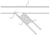
도 8은 본 발명에 따른 선형 절개부를 갖지 않는 H 사이드 브랜치 혈관용 스텐트를 나타내는 요부 측면도이고, 도 9는 도 8에 도시된 H 사이드 브랜치 혈관용 스텐트를 이용하여 주혈관 내에 시술하는 방법을 나타내는 개념도이며, 도 10은 본 발명에 따른 선형 절개부를 갖는 H 사이드 브랜치 혈관용 스텐트를 나타내는 요부 측면도이고, 도 11는 도 10에 도시된 H 사이드 브랜치 혈관용 스텐트를 이용하여 주혈관 내에 시술하는 방법을 나타내는 개념도이다.8 is a side view illustrating a main portion of the H side branch vessel stent having no linear incision according to the present invention, and FIG. 9 is a conceptual diagram illustrating a method of performing treatment in a main blood vessel using the H side branch vessel stent shown in FIG. 8. 10 is a main portion side view showing a H side branch vascular stent having a linear incision according to the present invention, and FIG. 11 shows a method of treatment in a main blood vessel using the H side branch vascular stent shown in FIG. 10. Conceptual diagram.
분지혈관(2) 개구부에 발생된 협착 소견에 대한 치료로서 이상적인 스텐트 시술이 이루어지기 위해서는 첫째, 분지혈관(2) 개구부가 스텐트에 의하여 완전히 둘러 쌓인 상태로 지지되어야 하며, 둘째, 주혈관과 분지혈관 사이의 경계부에 스 텐트가 밀집되는 현상이 없어야 하고, 마지막으로 주혈관 내에 위치된 스텐트가 주혈관의 내벽에 간극 없이 밀착되어야 한다.In order for the ideal stent procedure to be performed for the treatment of stenosis in the branched blood vessels (2), first, the branched blood vessels (2) should be fully supported by the stent. Second, the main and branch blood vessels There should be no dense stent at the boundary between them, and finally, the stent located in the main blood vessel should be in close contact with the inner wall of the main blood vessel without gap.
이에 대하여, 본 발명에 따른 H 사이드 브랜치 혈관용 스텐트(10)에서는 제 2 스텐트(40)의 선단부에 개구부를 형성하여, 제 2 스텐트(40)에 의해 분지혈관(2)의 내벽이 완전히 둘러싼 형태로 지지될 수 있으며, 주혈관(1)과 분지혈과(2) 사이의 경계부에 브릿지(30)를 위치시킴으로써 주혈관(1)과 분지혈관(2) 사이에 스텐트가 밀집되는 현상을 방지할 수 있다.In contrast, in the H side branch
도 8및 도 9을 참조하면, 제 1 스텐트(20)는 셀구조를 가지고 있으므로, 직경이 조절 가능하며, 이때 제 1 스텐트의 직경방향으로 가압 팽창시킴으로써 직경을 확장시킬 수 있다. 주혈관(1) 내에 제 1 스텐트(20)가 위치하게 되면, 직경방향으로 가압 팽창시킴으로써 제 1 스텐트(20)를 주혈관(1)의 내벽(일부영역)에 완전히 밀착시킬 수 있다.Referring to FIGS. 8 and 9, since the
이와는 다르게, 도 10 및 도 11을 참조하면, 제 1 스텐트(20)의 상단부에는 선형 절개부가 형성되어 있으므로, 제 1 스텐트(20)의 직경이 조절 가능하며, 이때 직경방향으로 가압하여 직경을 확장시킬 수 있다. 주혈관(1) 내에 제 1 스텐트(20)가 위치하게 되면, 직경방향으로 가압함으로써 제 1 스텐트(20)를 주혈관(1)의 내벽(일부영역)에 완전히 밀착시킬 수 있다.Unlike this, referring to FIGS. 10 and 11, since a linear incision is formed at the upper end of the
이후, 새로운 스텐트(50)를 주혈관 내에 삽입하여 분지부 병변의 치료를 완료할 수 있다.Thereafter, a
본 발명의 일 실시예에 따른 H 사이드 브랜치 혈관용 스텐트(10)를 이용한 시술방법은 경피적 관상동맥 중재시술과 기술적인 측면에서 유사하다.The treatment method using the H side branch
즉, 도 12 및 도 13을 참조하면, 분지부 병변에서 주혈관과 분지혈관으로 유도 와이어(101)를 각각 삽입한 후, 유도 와이어(101)를 따라 풍선(102)에 H 사이드 브랜치 혈관용 스텐트(10)를 수용시킨 상태에서 풍선 카테터(100)를 주혈관(1)과 분지혈관(2)으로 진행시켜 심하게 협착된 부위를 확장시킴으로써 병소 부위로 스텐트(10) 운반이 용이하도록 충분한 공간을 확보한다.That is, referring to FIGS. 12 and 13, after inserting the
이후, 분지혈관(2)의 직경과 분지각도에 적합한 H 사이드 브랜치 혈관용 스텐트(10)를 선택하여, 풍선 카테터(100)를 통해 병변 주위에 위치시킨다.Thereafter, the H side
이후, 마커(22, 43)에 유의하여 제 2 스텐트를 분지혈관(2)의 개구부에 정확히 위치시키고, 제 1 스텐트를 직경방향으로 가압하여 팽창시켜 주혈관(1)의 내벽에 밀착시킨다.Subsequently, paying attention to the
마지막으로, 도 11을 통해 설명한 바와 같이, 새로운 스텐트를 주혈관의 내벽에 위치시키고, 주혈관(1)과 분지혈관(2)에 풍선 확장술을 시행함으로써 분지부 병변의 치료를 마치게 된다.Finally, as described with reference to FIG. 11, the new stent is placed on the inner wall of the main blood vessel, and balloon dilatation is performed on the
한편, 이와는 다르게, 새로운 스텐트를 사용하지 않고도 도 9를 통해 설명한 바와 같이, 제 1 스텐트(20)를 팽창시켜, 주혈관(1)의 내벽에 밀착시킬 수 있다.On the other hand, differently, as described with reference to FIG. 9 without using a new stent, the
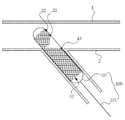
도 14는 도 1에 도시된 H 사이드 브랜치 혈관용 스텐트가 이중 풍선 도자에 둘러싸인 상태의 개념도로서, 이중 풍선 도자(200)는 혈관의 굴곡에 따라 꺽일 수 있도록, 전단풍선(203)과 후단풍선(202)을 포함하는 풍선부 및 중앙충(201)을 포함한다.FIG. 14 is a conceptual view illustrating a state in which the stent for H side branch vessel shown in FIG. 1 is surrounded by a double balloon pottery, and the
이때, 제 1 스텐트(20)는 전단풍선(203)내에 배치될 수 있고, 제 2 스텐트(40)는 후단풍선(202)내에 배치될 수 있으며, 이중 풍선 도자(200)는 스텐트의 브릿지(30) 부분에서 꺽일 수 있다.At this time, the
위에서 설명된 본 발명의 바람직한 실시예는 예시의 목적을 위해 개시된 것이고, 본 발명에 대한 통상의 지식을 가지는 당업자라면 본 발명의 사상과 범위 안에서 다양한 수정, 변경, 부가가 가능할 것이며, 이러한 수정, 변경 및 부가는 하기의 특허청구범위에 속하는 것으로 보아야 할 것이다.Preferred embodiments of the present invention described above are disclosed for purposes of illustration, and those skilled in the art having various ordinary knowledge of the present invention may make various modifications, changes, and additions within the spirit and scope of the present invention. And additions should be considered to be within the scope of the following claims.
도 1은 관상동맥 분지부 병변(B)을 나타내는 개념도.1 is a conceptual diagram showing coronary branching lesion (B).
도 2 및 도 3은 종래 관상동맥 분지부 병변에 사용되는 스텐트의 시술 상태를 나타내는 개념도.2 and 3 is a conceptual diagram showing the state of the operation of the stent used in conventional coronary branch lesions.
도 4는 본 발명의 일 실시예에 따른 H 사이드 브랜치 혈관용 스텐트를 나타내는 사시도.Figure 4 is a perspective view showing a stent for H side branch vessels according to an embodiment of the present invention.
도 5는 도 4에 도시된 H 사이드 브랜치 혈관용 스텐트를 펼친 상태의 상세 평면도.Figure 5 is a detailed plan view of the unfolded state of the stent for H side branch blood vessel shown in FIG.
도 6은 본 발명의 일 실시예에 따른 H 사이드 브랜치 혈관용 스텐트를 나타내는 요부 측면도.Figure 6 is a side view showing the main portion showing the stent for H side branch blood vessels according to an embodiment of the present invention.
도 7은 도 4에 도시된 H 사이드 브랜치 혈관용 스텐트가 시술된 상태의 단면도.FIG. 7 is a cross-sectional view of the stent for H side branch vessel shown in FIG. 4.
도 8은 본 발명에 따른 선형 절개부를 갖지 않는 H 사이드 브랜치 혈관용 스텐트를 나타내는 요부 측면도.Figure 8 is a side view of the main part showing the stent for H side branch vessels without a linear incision in accordance with the present invention.
도 9는 도 8에 도시된 H 사이드 브랜치 혈관용 스텐트를 이용하여 주혈관 내에 시술하는 방법을 나타내는 개념도.FIG. 9 is a conceptual diagram illustrating a method of treating in a main blood vessel using the H side branch vein stent shown in FIG. 8. FIG.
도 10은 본 발명에 따른 선형 절개부를 갖는 H 사이드 브랜치 혈관용 스텐트를 나타내는 요부 측면도.10 is a side view of a main portion showing a stent for an H side branch blood vessel having a linear incision according to the present invention;
도 11는 도 10에 도시된 H 사이드 브랜치 혈관용 스텐트를 이용하여 주혈관 내에 시술하는 방법을 나타내는 개념도.FIG. 11 is a conceptual diagram illustrating a method of treating in a main blood vessel using the stent for H side branch blood vessel shown in FIG. 10.
도 12 및 도 13은 본 발명의 일 실시예에 따른 H 사이드 브랜치 혈관용 스텐트를 이용하여 시술하는 과정을 나타내는 개념도.12 and 13 are conceptual views illustrating a procedure of using the H side branch vessel stent according to an embodiment of the present invention.
도 14는 도 1에 도시된 H 사이드 브랜치 혈관용 스텐트가 이중 풍선 도자에 둘러싸인 상태의 개념도.14 is a conceptual diagram of a state in which the stent for H side branch vessel shown in FIG.
Claims (23)
Translated fromKoreanPriority Applications (4)
| Application Number | Priority Date | Filing Date | Title |
|---|---|---|---|
| KR1020090041769AKR101073035B1 (en) | 2009-05-13 | 2009-05-13 | H Side-branch Stent |
| US13/320,224US20120116500A1 (en) | 2009-05-13 | 2009-11-03 | H-Side Branch Stent |
| JP2012510729AJP5777607B2 (en) | 2009-05-13 | 2009-11-03 | H-side branch vessel stent |
| PCT/KR2009/006423WO2010131823A1 (en) | 2009-05-13 | 2009-11-03 | H-side branch stent |
Applications Claiming Priority (1)
| Application Number | Priority Date | Filing Date | Title |
|---|---|---|---|
| KR1020090041769AKR101073035B1 (en) | 2009-05-13 | 2009-05-13 | H Side-branch Stent |
Publications (2)
| Publication Number | Publication Date |
|---|---|
| KR20100122728A KR20100122728A (en) | 2010-11-23 |
| KR101073035B1true KR101073035B1 (en) | 2011-10-12 |
Family
ID=43085180
Family Applications (1)
| Application Number | Title | Priority Date | Filing Date |
|---|---|---|---|
| KR1020090041769AExpired - Fee RelatedKR101073035B1 (en) | 2009-05-13 | 2009-05-13 | H Side-branch Stent |
Country Status (4)
| Country | Link |
|---|---|
| US (1) | US20120116500A1 (en) |
| JP (1) | JP5777607B2 (en) |
| KR (1) | KR101073035B1 (en) |
| WO (1) | WO2010131823A1 (en) |
Cited By (1)
| Publication number | Priority date | Publication date | Assignee | Title |
|---|---|---|---|---|
| KR101586615B1 (en) | 2015-09-23 | 2016-01-19 | 신경민 | Branched stent |
Families Citing this family (12)
| Publication number | Priority date | Publication date | Assignee | Title |
|---|---|---|---|---|
| US7147661B2 (en) | 2001-12-20 | 2006-12-12 | Boston Scientific Santa Rosa Corp. | Radially expandable stent |
| AU2007258592B2 (en) | 2006-06-06 | 2012-10-25 | Cook Incorporated | Stent with a crush-resistant zone |
| KR101137896B1 (en)* | 2009-11-12 | 2012-05-02 | 연세대학교 산학협력단 | Branch Vessel Protection Stent on Branch Lesions |
| US9254208B2 (en)* | 2013-03-14 | 2016-02-09 | Thomas Ischinger | Oblique stent |
| CN103720529B (en)* | 2013-12-30 | 2017-02-08 | 先健科技(深圳)有限公司 | Arcus aortae intraoperative stent and method for manufacturing stent |
| DE102016104302A1 (en)* | 2016-03-09 | 2017-09-14 | Optimed Medizinische Lnstrumente Gmbh | STENT FOR USE AT BIFURCATIONS |
| US10076433B1 (en)* | 2017-05-08 | 2018-09-18 | Vadim Bernshtein | Intravascular bifurication zone implants and crimping and deployment methods thereof |
| EP3711717A4 (en)* | 2017-11-17 | 2020-12-23 | Hangzhou Endonom Medtech Co., Ltd | Endovascular stent |
| CN108888390A (en)* | 2018-05-23 | 2018-11-27 | 上普博源(北京)生物科技有限公司 | A kind of bionical bifurcated special stand of polymer and preparation method thereof |
| FI3941392T3 (en) | 2019-03-20 | 2025-07-28 | Inqb8 Medical Tech Llc | Aortic dissection implant |
| KR102438979B1 (en)* | 2020-08-06 | 2022-09-01 | 주식회사 에스앤지바이오텍 | Bifurcated stents and methods of use thereof |
| AU2021375762A1 (en)* | 2020-11-09 | 2023-06-15 | Venova Medical, Inc. | Endovascular implants and devices and methods for accurate placement |
Citations (2)
| Publication number | Priority date | Publication date | Assignee | Title |
|---|---|---|---|---|
| US20040186560A1 (en)* | 2002-08-31 | 2004-09-23 | Tbd | Stent for bifurcated vessels |
| US20080161903A1 (en)* | 2000-05-30 | 2008-07-03 | Jacques Sequin | Noncylindrical Drug Eluting Stent for Treating Vascular Bifurcations |
Family Cites Families (7)
| Publication number | Priority date | Publication date | Assignee | Title |
|---|---|---|---|---|
| DE69528216T2 (en)* | 1994-06-17 | 2003-04-17 | Terumo K.K., Tokio/Tokyo | Process for the production of a permanent stent |
| JP3585978B2 (en)* | 1995-02-16 | 2004-11-10 | テルモ株式会社 | Instrument for treating stenosis in body cavity |
| FR2733682B1 (en)* | 1995-05-04 | 1997-10-31 | Dibie Alain | ENDOPROSTHESIS FOR THE TREATMENT OF STENOSIS ON BIFURCATIONS OF BLOOD VESSELS AND LAYING EQUIPMENT THEREFOR |
| UA58485C2 (en)* | 1996-05-03 | 2003-08-15 | Медінол Лтд. | Method for manufacture of bifurcated stent (variants) and bifurcated stent (variants) |
| US6344056B1 (en)* | 1999-12-29 | 2002-02-05 | Edwards Lifesciences Corp. | Vascular grafts for bridging a vessel side branch |
| US7918884B2 (en)* | 2003-02-25 | 2011-04-05 | Cordis Corporation | Stent for treatment of bifurcated lesions |
| US7632304B2 (en)* | 2005-09-07 | 2009-12-15 | Rbkpark Llc | Coronary stent |
- 2009
- 2009-05-13KRKR1020090041769Apatent/KR101073035B1/ennot_activeExpired - Fee Related
- 2009-11-03USUS13/320,224patent/US20120116500A1/ennot_activeAbandoned
- 2009-11-03JPJP2012510729Apatent/JP5777607B2/ennot_activeExpired - Fee Related
- 2009-11-03WOPCT/KR2009/006423patent/WO2010131823A1/ennot_activeCeased
Patent Citations (2)
| Publication number | Priority date | Publication date | Assignee | Title |
|---|---|---|---|---|
| US20080161903A1 (en)* | 2000-05-30 | 2008-07-03 | Jacques Sequin | Noncylindrical Drug Eluting Stent for Treating Vascular Bifurcations |
| US20040186560A1 (en)* | 2002-08-31 | 2004-09-23 | Tbd | Stent for bifurcated vessels |
Cited By (1)
| Publication number | Priority date | Publication date | Assignee | Title |
|---|---|---|---|---|
| KR101586615B1 (en) | 2015-09-23 | 2016-01-19 | 신경민 | Branched stent |
Also Published As
| Publication number | Publication date |
|---|---|
| WO2010131823A1 (en) | 2010-11-18 |
| US20120116500A1 (en) | 2012-05-10 |
| JP5777607B2 (en) | 2015-09-09 |
| KR20100122728A (en) | 2010-11-23 |
| JP2012526601A (en) | 2012-11-01 |
Similar Documents
| Publication | Publication Date | Title |
|---|---|---|
| KR101073035B1 (en) | H Side-branch Stent | |
| US6565598B1 (en) | Stent with a closed structure | |
| US6875227B2 (en) | Metal stent for insertion in coronary artery | |
| JP6920355B2 (en) | Guide extension catheter with grooved push member segment | |
| US6709451B1 (en) | Channeled vascular stent apparatus and method | |
| US20090171439A1 (en) | Temporary Stent | |
| JP5114385B2 (en) | Delivery catheter | |
| JP4630274B2 (en) | Stent to be placed in the lumen opening | |
| JP2005535369A (en) | Centering catheter | |
| US20080051878A1 (en) | Stent for treating vulnerable plaque | |
| EP2656818B1 (en) | Absorbable blood vessel stent | |
| JP2013524898A (en) | Branch vessel stent | |
| WO2012062144A1 (en) | Bifurcation blood vessel stent | |
| CN103230640A (en) | Medicine-carrying cutting balloon dilating catheter | |
| US20080097570A1 (en) | Systems and Methods for Local Bioactive Material Delivery | |
| CN109431664B (en) | Asymmetric intravascular stent | |
| JP2021501007A (en) | Exoskeleton device with expandable parts for knurling | |
| US8292942B2 (en) | Double-balloon delivery system for an implantable eccentric stent | |
| KR20110088841A (en) | Balloon catheter and vasodilation device using same | |
| US20130297007A1 (en) | Apparatuses and methods for guiding endoluminal devices through body lumens | |
| JP2008237880A (en) | Intraluminal medical device having variable axial flexibility about circumference of the device | |
| JP7043589B2 (en) | Stent | |
| JP5560345B2 (en) | Stent for branch vessel protection in bifurcation lesions | |
| CN110251284B (en) | Expandable stent | |
| CN213789516U (en) | Guide wire cutting medicine balloon |
Legal Events
| Date | Code | Title | Description |
|---|---|---|---|
| A201 | Request for examination | ||
| PA0109 | Patent application | St.27 status event code:A-0-1-A10-A12-nap-PA0109 | |
| PA0201 | Request for examination | St.27 status event code:A-1-2-D10-D11-exm-PA0201 | |
| P11-X000 | Amendment of application requested | St.27 status event code:A-2-2-P10-P11-nap-X000 | |
| P13-X000 | Application amended | St.27 status event code:A-2-2-P10-P13-nap-X000 | |
| D13-X000 | Search requested | St.27 status event code:A-1-2-D10-D13-srh-X000 | |
| D14-X000 | Search report completed | St.27 status event code:A-1-2-D10-D14-srh-X000 | |
| PG1501 | Laying open of application | St.27 status event code:A-1-1-Q10-Q12-nap-PG1501 | |
| E902 | Notification of reason for refusal | ||
| PE0902 | Notice of grounds for rejection | St.27 status event code:A-1-2-D10-D21-exm-PE0902 | |
| T11-X000 | Administrative time limit extension requested | St.27 status event code:U-3-3-T10-T11-oth-X000 | |
| E13-X000 | Pre-grant limitation requested | St.27 status event code:A-2-3-E10-E13-lim-X000 | |
| P11-X000 | Amendment of application requested | St.27 status event code:A-2-2-P10-P11-nap-X000 | |
| P13-X000 | Application amended | St.27 status event code:A-2-2-P10-P13-nap-X000 | |
| E701 | Decision to grant or registration of patent right | ||
| PE0701 | Decision of registration | St.27 status event code:A-1-2-D10-D22-exm-PE0701 | |
| GRNT | Written decision to grant | ||
| PR0701 | Registration of establishment | St.27 status event code:A-2-4-F10-F11-exm-PR0701 | |
| PR1002 | Payment of registration fee | St.27 status event code:A-2-2-U10-U11-oth-PR1002 Fee payment year number:1 | |
| PG1601 | Publication of registration | St.27 status event code:A-4-4-Q10-Q13-nap-PG1601 | |
| PN2301 | Change of applicant | St.27 status event code:A-5-5-R10-R13-asn-PN2301 St.27 status event code:A-5-5-R10-R11-asn-PN2301 | |
| P22-X000 | Classification modified | St.27 status event code:A-4-4-P10-P22-nap-X000 | |
| R18-X000 | Changes to party contact information recorded | St.27 status event code:A-5-5-R10-R18-oth-X000 | |
| PN2301 | Change of applicant | St.27 status event code:A-5-5-R10-R13-asn-PN2301 St.27 status event code:A-5-5-R10-R11-asn-PN2301 | |
| R18-X000 | Changes to party contact information recorded | St.27 status event code:A-5-5-R10-R18-oth-X000 | |
| FPAY | Annual fee payment | Payment date:20141002 Year of fee payment:4 | |
| PR1001 | Payment of annual fee | St.27 status event code:A-4-4-U10-U11-oth-PR1001 Fee payment year number:4 | |
| FPAY | Annual fee payment | Payment date:20151008 Year of fee payment:5 | |
| PR1001 | Payment of annual fee | St.27 status event code:A-4-4-U10-U11-oth-PR1001 Fee payment year number:5 | |
| FPAY | Annual fee payment | Payment date:20161005 Year of fee payment:6 | |
| PR1001 | Payment of annual fee | St.27 status event code:A-4-4-U10-U11-oth-PR1001 Fee payment year number:6 | |
| LAPS | Lapse due to unpaid annual fee | ||
| PC1903 | Unpaid annual fee | St.27 status event code:A-4-4-U10-U13-oth-PC1903 Not in force date:20171007 Payment event data comment text:Termination Category : DEFAULT_OF_REGISTRATION_FEE | |
| PC1903 | Unpaid annual fee | St.27 status event code:N-4-6-H10-H13-oth-PC1903 Ip right cessation event data comment text:Termination Category : DEFAULT_OF_REGISTRATION_FEE Not in force date:20171007 | |
| R18-X000 | Changes to party contact information recorded | St.27 status event code:A-5-5-R10-R18-oth-X000 | |
| PN2301 | Change of applicant | St.27 status event code:A-5-5-R10-R13-asn-PN2301 St.27 status event code:A-5-5-R10-R11-asn-PN2301 |