KR101072060B1 - Lighting device - Google Patents
Lighting deviceDownload PDFInfo
- Publication number
- KR101072060B1 KR101072060B1KR1020090107500AKR20090107500AKR101072060B1KR 101072060 B1KR101072060 B1KR 101072060B1KR 1020090107500 AKR1020090107500 AKR 1020090107500AKR 20090107500 AKR20090107500 AKR 20090107500AKR 101072060 B1KR101072060 B1KR 101072060B1
- Authority
- KR
- South Korea
- Prior art keywords
- light emitting
- heat dissipation
- lens
- emitting module
- module unit
- Prior art date
- Legal status (The legal status is an assumption and is not a legal conclusion. Google has not performed a legal analysis and makes no representation as to the accuracy of the status listed.)
- Expired - Fee Related
Links
Images


Classifications
- F—MECHANICAL ENGINEERING; LIGHTING; HEATING; WEAPONS; BLASTING
- F21—LIGHTING
- F21V—FUNCTIONAL FEATURES OR DETAILS OF LIGHTING DEVICES OR SYSTEMS THEREOF; STRUCTURAL COMBINATIONS OF LIGHTING DEVICES WITH OTHER ARTICLES, NOT OTHERWISE PROVIDED FOR
- F21V29/00—Protecting lighting devices from thermal damage; Cooling or heating arrangements specially adapted for lighting devices or systems
- F21V29/50—Cooling arrangements
- F21V29/70—Cooling arrangements characterised by passive heat-dissipating elements, e.g. heat-sinks
- F21V29/83—Cooling arrangements characterised by passive heat-dissipating elements, e.g. heat-sinks the elements having apertures, ducts or channels, e.g. heat radiation holes
- F—MECHANICAL ENGINEERING; LIGHTING; HEATING; WEAPONS; BLASTING
- F21—LIGHTING
- F21V—FUNCTIONAL FEATURES OR DETAILS OF LIGHTING DEVICES OR SYSTEMS THEREOF; STRUCTURAL COMBINATIONS OF LIGHTING DEVICES WITH OTHER ARTICLES, NOT OTHERWISE PROVIDED FOR
- F21V17/00—Fastening of component parts of lighting devices, e.g. shades, globes, refractors, reflectors, filters, screens, grids or protective cages
- F21V17/10—Fastening of component parts of lighting devices, e.g. shades, globes, refractors, reflectors, filters, screens, grids or protective cages characterised by specific fastening means or way of fastening
- F—MECHANICAL ENGINEERING; LIGHTING; HEATING; WEAPONS; BLASTING
- F21—LIGHTING
- F21V—FUNCTIONAL FEATURES OR DETAILS OF LIGHTING DEVICES OR SYSTEMS THEREOF; STRUCTURAL COMBINATIONS OF LIGHTING DEVICES WITH OTHER ARTICLES, NOT OTHERWISE PROVIDED FOR
- F21V21/00—Supporting, suspending, or attaching arrangements for lighting devices; Hand grips
- F21V21/002—Supporting, suspending, or attaching arrangements for lighting devices; Hand grips making direct electrical contact, e.g. by piercing
- F—MECHANICAL ENGINEERING; LIGHTING; HEATING; WEAPONS; BLASTING
- F21—LIGHTING
- F21V—FUNCTIONAL FEATURES OR DETAILS OF LIGHTING DEVICES OR SYSTEMS THEREOF; STRUCTURAL COMBINATIONS OF LIGHTING DEVICES WITH OTHER ARTICLES, NOT OTHERWISE PROVIDED FOR
- F21V5/00—Refractors for light sources
- F21V5/04—Refractors for light sources of lens shape
- F—MECHANICAL ENGINEERING; LIGHTING; HEATING; WEAPONS; BLASTING
- F21—LIGHTING
- F21Y—INDEXING SCHEME ASSOCIATED WITH SUBCLASSES F21K, F21L, F21S and F21V, RELATING TO THE FORM OR THE KIND OF THE LIGHT SOURCES OR OF THE COLOUR OF THE LIGHT EMITTED
- F21Y2115/00—Light-generating elements of semiconductor light sources
- F21Y2115/10—Light-emitting diodes [LED]
- Y—GENERAL TAGGING OF NEW TECHNOLOGICAL DEVELOPMENTS; GENERAL TAGGING OF CROSS-SECTIONAL TECHNOLOGIES SPANNING OVER SEVERAL SECTIONS OF THE IPC; TECHNICAL SUBJECTS COVERED BY FORMER USPC CROSS-REFERENCE ART COLLECTIONS [XRACs] AND DIGESTS
- Y10—TECHNICAL SUBJECTS COVERED BY FORMER USPC
- Y10S—TECHNICAL SUBJECTS COVERED BY FORMER USPC CROSS-REFERENCE ART COLLECTIONS [XRACs] AND DIGESTS
- Y10S362/00—Illumination
- Y10S362/80—Light emitting diode
Landscapes
- Engineering & Computer Science (AREA)
- General Engineering & Computer Science (AREA)
- Non-Portable Lighting Devices Or Systems Thereof (AREA)
- Arrangement Of Elements, Cooling, Sealing, Or The Like Of Lighting Devices (AREA)
Abstract
Translated fromKoreanDescription
Translated fromKorean실시예는 조명 장치에 관한 것이다.Embodiments relate to a lighting device.
발광 다이오드(LED)는 전기 에너지를 빛으로 변환하는 반도체 소자의 일종이다. 발광 다이오드는 형광등, 백열등 등 기존의 광원에 비해 저소비전력, 반영구적인 수명, 빠른 응답속도, 안전성, 환경친화성의 장점을 가진다. 이에 기존의 광원을 발광 다이오드로 대체하기 위한 많은 연구가 진행되고 있으며, 발광 다이오드는 실내외에서 사용되는 각종 램프, 액정표시장치, 전광판, 가로등 등의 조명 장치의 광원으로서 사용이 증가되고 있는 추세이다.Light emitting diodes (LEDs) are a type of semiconductor device that converts electrical energy into light. Light emitting diodes have the advantages of low power consumption, semi-permanent life, fast response speed, safety and environmental friendliness compared to conventional light sources such as fluorescent and incandescent lamps. Accordingly, many researches are being conducted to replace existing light sources with light emitting diodes, and the use of light emitting diodes is increasing as a light source for lighting devices such as various lamps, liquid crystal displays, electronic displays, and street lamps that are used indoors and outdoors.
실시예는 새로운 구조를 갖는 조명 장치를 제공한다.The embodiment provides a lighting device having a new structure.
실시예는 내전압이 향상된 조명 장치를 제공한다.The embodiment provides a lighting device having improved withstand voltage.
실시예는 방수 특성이 양호한 조명 장치를 제공한다.The embodiment provides a lighting device having good waterproof characteristics.
실시예는 취급이 용이한 조명 장치를 제공한다.Embodiments provide an illumination device that is easy to handle.
실시예는 방열 특성이 양호한 조명 장치를 제공한다.The embodiment provides a lighting device having good heat dissipation characteristics.
실시예는 부품의 교체가 용이한 조명 장치를 제공한다.The embodiment provides a lighting device that is easy to replace parts.
실시예에 따른 조명 장치는 삽입부를 포함하는 내부 케이스; 상기 내부 케이스의 삽입부가 삽입되는 제1 수납홈을 포함하는 방열몸체; 상기 방열몸체의 하면에 빛을 방출하는 발광모듈부; 상기 발광모듈부 아래에 렌즈; 상기 방열몸체 하부의 둘레 영역에 결합되어 상기 발광모듈부 및 상기 렌즈를 상기 방열몸체에 견고히 고정시키는 가이드부재; 및 상기 방열몸체의 외측에 외부 케이스를 포함한다.Lighting device according to the embodiment includes an inner case including an insert; A heat dissipation body including a first receiving groove into which the insert of the inner case is inserted; A light emitting module unit for emitting light on the lower surface of the heat dissipation body; A lens under the light emitting module unit; A guide member coupled to a circumferential region of the lower portion of the heat dissipation body to firmly fix the light emitting module unit and the lens to the heat dissipation body; And an outer case outside the heat dissipation body.
실시예는 새로운 구조를 갖는 조명 장치를 제공할 수 있다.The embodiment can provide a lighting device having a new structure.
실시예는 내전압이 향상된 조명 장치를 제공할 수 있다.The embodiment can provide a lighting device having improved withstand voltage.
실시예는 방수 특성이 양호한 조명 장치를 제공할 수 있다.The embodiment can provide a lighting device having good waterproof characteristics.
실시예는 취급이 용이한 조명 장치를 제공할 수 있다.Embodiments can provide a lighting device that is easy to handle.
실시예는 방열 특성이 양호한 조명 장치를 제공할 수 있다.The embodiment can provide a lighting device having good heat dissipation characteristics.
실시예는 부품의 교체가 용이한 조명 장치를 제공할 수 있다.Embodiments can provide a lighting device that is easy to replace parts.
실시예들의 설명에 있어서, 각 층(막), 영역, 패턴 또는 구조물들이 기판, 각 층(막), 영역, 패드 또는 패턴들의 "위(on)"에 또는 "아래(under)"에 형성되는 것으로 기재되는 경우에 있어, "위(on)"와 "아래(under)"는 "직접(directly)" 또는 "다른 층을 개재하여 (indirectly)" 형성되는 것을 모두 포함한다. 또한 각 층의 위 또는 아래에 대한 기준은 도면을 기준으로 설명한다.In the description of the embodiments, it is to be understood that each layer (film), region, pattern or structure is formed "on" or "under" a substrate, each layer The terms " on "and " under " encompass both being formed" directly "or" indirectly " In addition, the criteria for the top or bottom of each layer will be described with reference to the drawings.
도면에서 각층의 두께나 크기는 설명의 편의 및 명확성을 위하여 과장되거나 생략되거나 또는 개략적으로 도시되었다. 또한 각 구성요소의 크기는 실제크기를 전적으로 반영하는 것은 아니다.In the drawings, the thickness or size of each layer is exaggerated, omitted, or schematically illustrated for convenience and clarity of description. In addition, the size of each component does not necessarily reflect the actual size.
이하, 첨부된 도면을 참조하여 실시예에 따른 조명 장치에 대해 설명한다.Hereinafter, a lighting apparatus according to an embodiment will be described with reference to the accompanying drawings.
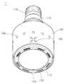
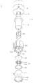
도 1은 실시예에 따른 조명 장치(1)를 아래 방향에서 바라본 사시도이고, 도 2는 상기 조명 장치(1)를 윗 방향에서 바라본 사시도이고, 도 3은 상기 조명 장치(1)의 분해 사시도이고, 도 4는 상기 조명 장치(1)의 단면을 나타내는 도면이다.1 is a perspective view of the
도 1 내지 도 4를 참조하면, 상기 조명 장치(1)는 상부에 연결 단자(175)를 포함하고, 하부에 삽입부(174)를 포함하는 내부 케이스(170)와, 상기 내부 케이스(170)의 삽입부(174)가 삽입되는 제1 수납홈(151)을 포함하는 방열몸체(150)와, 상기 방열몸체(150)의 하면에 빛을 방출하며, 하나 또는 복수의 발광 소자(131)를 포함하는 발광모듈부(130)와, 상기 방열몸체(150) 하부의 둘레 영역에 결합되어 상 기 발광모듈부(130)를 상기 방열몸체(150)에 견고히 고정시키는 가이드부재(100)와, 상기 방열몸체(150)의 외측에 외부 케이스(180)를 포함한다.1 to 4, the
상기 방열몸체(150)는 양면에 수납홈(151,152)을 포함하여 상기 발광모듈부(130) 및 상기 전원제어부(160)를 수용하며, 상기 발광모듈부(130) 또는/및 상기 전원제어부(160)에서 생성된 열을 방출시키는 역할을 한다.The
구체적으로는, 도 3 및 도 4에 도시된 것처럼, 상기 방열몸체(150)의 상면에는 상기 전원제어부(160)가 배치되는 상기 제1 수납홈(151)이 형성되고, 상기 방열몸체(150)의 하면에는 상기 발광모듈부(130)가 배치되는 제2 수납홈(152)이 형성될 수 있다.Specifically, as shown in FIGS. 3 and 4, the
상기 방열몸체(150)의 외측면은 요철 구조를 가질 수 있으며, 상기 요철 구조에 의해 상기 방열몸체(150)의 표면적이 증가하여 방열 효율이 향상될 수 있다.The outer surface of the
또한, 상기 방열몸체(150)는 열 방출 효율이 뛰어난 금속 재질 또는 수지 재질로 형성될 수 있으나, 이에 대해 한정하지는 않는다. 예를 들어, 상기 방열몸체(150)의 재질은 알루미늄(Al), 니켈(Ni), 구리(Cu), 은(Ag), 주석(Sn), 마그네슘(Mg) 중 적어도 하나를 포함할 수 있다.In addition, the
상기 발광모듈부(130)는 상기 방열몸체(150)의 하면에 형성된 상기 제2 수납홈(152)에 배치될 수 있다. 상기 발광모듈부(130)는 기판(132)과, 상기 기판(132)에 탑재되는 상기 하나 또는 복수의 발광 소자(131)를 포함할 수 있다.The light
상기 하나 또는 복수의 발광 소자(131) 각각은 적어도 하나의 발광 다이오드(LED : Light Emitting Diode)를 포함할 수 있다. 상기 발광 다이오드는 적색, 녹색, 청색 또는 백색의 빛을 각각 발광하는 적색, 녹색, 청색 또는 백색 발광 다이오드일 수 있으나, 그 종류나 수에 대해 한정하지는 않는다.Each of the one or more
상기 발광모듈부(130)는 상기 방열몸체(150)의 바닥면을 관통하는 관통홀(153)을 통해 상기 전원제어부(160)와 배선 등에 의해 전기적으로 연결되어 전원을 제공받음으로써 구동될 수 있다.The light
이때, 상기 관통홀(153)에는 제2 보호링(155)이 형성되어, 상기 발광모듈부(130) 및 상기 방열몸체(150) 사이로 수분 및 이물질이 침투하는 것을 방지하고, 상기 배선이 상기 방열몸체(150)과 접촉함으로써 발생할 수 있는 전기적 쇼트, 내전압, EMI, EMS 등의 문제를 방지할 수 있다.In this case, a
상기 발광모듈부(130)의 하면에는 방열판(140)이 부착될 수 있으며, 상기 방열판(140)은 상기 제2 수납홈(152)에 부착될 수 있다. 또는, 상기 발광모듈부(130)와 상기 방열판(140)은 일체로 형성될 수도 있다. 상기 방열판(140)에 의해 상기 발광모듈부(130)에서 생성된 열이 상기 방열몸체(150)로 더욱 효과적으로 전달될 수 있다.The
상기 발광모듈부(130)는 상기 가이드부재(100)에 의해 상기 제2 수납홈(152)에 견고히 고정될 수 있다. 상기 가이드부재(100)는 상기 발광모듈부(130)에 탑재된 상기 하나 또는 복수의 발광 소자(131)들이 노출되도록 개구부(101)를 가지며, 상기 발광모듈부(130)의 둘레면을 상기 방열몸체(150)의 제2 수납홈(152)에 압착함으로써 고정시킬 수 있다.The light
또한, 상기 가이드부재(100)에는 상기 방열몸체(150) 및 상기 외부 케이 스(180) 사이로 공기가 흐르도록 할 수 있는 공기 유입 구조가 형성되어 상기 조명 장치(1)의 방열 효율을 극대화 시킬 수 있다. 상기 공기 유입 구조는 예를 들어, 상기 가이드부재(100)의 내측면과 외측면 사이에 형성되는 다수의 제1 방열홀(102) 또는 상기 가이드부재(100)의 내측면에 형성되는 요철 구조 일 수 있다. 이에 대해서는 자세히 후술한다.In addition, the
상기 가이드부재(100)와 상기 발광모듈부(130) 사이에는 렌즈(110) 및 제1 보호링(120) 중 적어도 하나가 포함될 수 있다.At least one of the
상기 렌즈(110)는 오목 렌즈, 볼록 렌즈, 파라볼라 형태의 렌즈, 프레넬 렌즈 등 다양한 형태를 가지는 것으로 선택되어 상기 발광모듈부(130)에서 방출되는 빛의 배광을 원하는 대로 조절할 수 있다. 또한, 상기 렌즈(110)는 형광체를 포함하여 상기 빛의 파장을 변화시키는 용도로 활용될 수도 있으며, 이에 대해 한정하지는 않는다.The
상기 제1 보호링(120)은 상기 가이드부재(100)와 상기 발광모듈부(130) 사이로 수분이나 이물질이 침투하는 것을 방지하는 동시에, 상기 발광모듈부(130)의 외측면 및 상기 방열몸체(150)의 내측면 사이를 이격시켜 상기 발광모듈부(130)가 상기 방열몸체(150)와 직접 접촉하는 것을 방지함으로써 상기 조명 장치(1)의 내전압, EMI, EMS 등을 향상시킬 수 있다.The first
상기 내부 케이스(170)는 도 3 및 도 4에 도시된 것처럼, 하부 영역에 상기 방열몸체(150)의 상기 제1 수납홈(151)에 삽입되는 삽입부(174)와, 상부 영역에 외부 전원과 전기적으로 연결되는 연결 단자(175)를 포함할 수 있다.As shown in FIGS. 3 and 4, the
상기 삽입부(174)의 측벽은 상기 전원제어부(160)와 상기 방열몸체(150) 사이에 배치되어, 둘 사이의 전기적 쇼트 등을 방지함으로써 내전압, EMI, EMS 등을 향상시킬 수 있다.Sidewalls of the
상기 연결 단자(175)는 소켓(socket) 형태를 갖는 외부 전원에 삽입됨으로써 상기 조명 장치(1)에 전원이 제공될 수 있다. 다만, 상기 연결 단자(175)의 형태는 상기 조명 장치(1)의 설계에 따라 다양하게 변형될 수 있으므로, 이에 대해 한정하지는 않는다.The
상기 방열몸체(150)의 제1 수납홈(151)에는 상기 전원제어부(160)가 배치될 수 있다. 상기 전원제어부(160)는 외부 전원으로부터 제공되는 교류 전원을 직류 전원으로 변환하는 직류변환장치, 상기 발광모듈부(130)의 구동을 제어하는 구동칩, 상기 발광모듈부(130)을 보호하기 위한 ESD(ElectroStatic Discharge) 보호 소자 등을 포함할 수 있으나 이에 대해 한정하지는 않는다.The
상기 외부 케이스(180)는 상기 내부 케이스(170)와 결합되어 상기 방열몸체(150), 발광모듈부(130), 전원제어부(160) 등을 수납하고, 상기 조명 장치(1)의 외관을 이룰 수 있다.The
상기 외부 케이스(180)는 원형의 단면을 가지는 것으로 도시되었으나, 다각형, 타원형 등의 단면을 가지도록 설계될 수도 있으며, 이에 대해 한정하지는 않는다.Although the
상기 외부 케이스(180)에 의해 상기 방열몸체(150)가 노출되지 않으므로 화상 사고 및 감전 사고를 방지될 수 있으며, 상기 조명 장치(1)의 취급성을 향상시 킬 수 있다.Since the
이하, 실시예에 따른 조명 장치(1)에 대해 각 구성 요소를 중심으로 상세히 설명한다.Hereinafter, the
<방열몸체(150)><The radiating
도 5는 상기 방열몸체(150)의 사시도이고, 도 6은 도 5의 A-A' 단면을 나타내는 단면도이다.5 is a perspective view of the
도 4 내지 도 6을 참조하면, 상기 방열몸체(150)의 제1면에는 상기 전원제어부(160)가 배치되는 제1 수납홈(151)이 형성되고, 상기 제1면의 반대면인 제2면에는 상기 발광모듈부(130)가 배치되는 제2 수납홈(152)이 형성될 수 있다.4 to 6, a first
다만, 상기 제1,2 수납홈(151,152)의 너비 및 깊이는 상기 전원제어부(160) 및 상기 발광모듈부(130)의 너비 및 두께에 따라 변화될 수 있다.However, the width and depth of the first and second receiving
상기 방열몸체(150)는 열 방출 효율이 뛰어난 금속 재질 또는 수지 재질로 형성될 수 있으나, 이에 대해 한정하지는 않는다. 예를 들어, 상기 방열몸체(150)의 재질은 알루미늄(Al), 니켈(Ni), 구리(Cu), 은(Ag), 주석(Sn) 중 적어도 하나를 포함할 수 있다.The
상기 방열몸체(150)의 외측면은 요철 구조를 가질 수 있으며, 상기 요철 구조에 의해 상기 방열몸체(150)의 표면적이 증가하여 방열 효율이 향상될 수 있다. 상기 요철(凹凸) 구조는 도시된 바와 같이, 일 방향으로 휘어지는 웨이브(wave) 형태의 철(凸) 구조를 포함할 수 있으나, 이에 대해서 한정하지는 않는다.The outer surface of the
상기 방열몸체(150)의 바닥면에는 상기 관통홀(153)이 형성될 수 있으며, 상기 관통홀(153)을 통해 상기 발광모듈부(130) 및 상기 전원제어부(160)가 배선에 의해 전기적으로 연결될 수 있다.The through
이때, 상기 관통홀(153)에는 상기 제2 보호링(155)이 결합되어, 상기 관통홀(153)을 통해 수분 및 이물질이 침투하는 것을 방지하고, 상기 배선이 상기 방열몸체(150)과 접촉함으로써 발생할 수 있는 전기적 쇼트(short) 등의 문제를 방지할 수 있다. 상기 제2 보호링(155)은 고무 재질, 실리콘 재질 또는 기타 전기 절연 재질로 형성될 수 있다.In this case, the
상기 방열몸체(150)의 하부 측면에는 상기 가이드부재(100)를 견고히 결합하기 위해 제1 체결부재(154)가 형성될 수 있다. 상기 제1 체결부재(154)에는 나사가 삽입될 수 있는 홀이 형성될 수 있으며, 상기 나사는 상기 가이드부재(100)를 상기 방열몸체(150)에 견고히 결합할 수 있다.A
또한, 상기 가이드부재(100)가 용이하게 결합되도록, 상기 가이드부재(100)가 결합되는 상기 방열몸체(150)의 하부 영역의 제1폭(P1)은 상기 방열몸체(150)의 다른 영역의 제2폭(P2)에 비해 좁을 수 있다. 다만, 이에 대해 한정하지는 않는다.In addition, the first width (P1) of the lower region of the
<발광모듈부(130) 및 제1 보호링(120)><
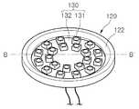
도 7은 상기 발광모듈부(130) 및 상기 제1 보호링(120)의 결합 사시도이고, 도 8은 도 7의 B-B' 단면을 나타내는 단면도이다.7 is a perspective view illustrating the light emitting
도 3, 도 7 및 도 8을 참조하면, 상기 발광모듈부(130)는 상기 방열몸 체(150)의 상기 제2 수납홈(152)에 배치되며, 상기 발광모듈부(130)의 둘레 영역에는 상기 제1 보호링(120)이 결합된다.3, 7 and 8, the light emitting
상기 발광모듈부(130)는 기판(132)과, 상기 기판(132)에 탑재되는 상기 하나 또는 복수의 발광 소자(131)를 포함할 수 있다.The light emitting
상기 기판(132)은 절연체에 회로 패턴이 인쇄된 것일 수 있으며, 예를 들어, 일반 인쇄회로기판(PCB : Printed Circuit Board), 메탈 코아(Metal Core) PCB, 연성(Flexible) PCB, 세라믹 PCB 등을 포함할 수 있다.The
또한, 상기 기판(132)은 빛을 효율적으로 반사하는 재질로 형성되거나, 표면이 빛이 효율적으로 반사되는 컬러, 예를 들어 백색, 은색 등으로 형성될 수 있다.In addition, the
상기 기판(132) 상에는 상기 하나 또는 복수의 발광 소자(131)가 탑재될 수 있다. 상기 하나 또는 복수의 발광 소자(131) 각각은 적어도 하나의 발광 다이오드(LED : Light Emitting Diode)를 포함할 수 있다. 상기 발광 다이오드는 적색, 녹색, 청색 또는 백색의 빛을 각각 발광하는 적색, 녹색, 청색 또는 백색 발광 다이오드일 수 있으나, 그 종류나 수에 대해 한정하지는 않는다.The one or more
한편, 상기 하나 또는 복수의 발광 소자(131)의 배치에 대해서는 한정하지 않는다. 다만, 실시예에서는 상기 발광모듈부(130) 아래로 배선이 형성되게 되는데, 상기 발광모듈부(130)의 영역 중 상기 배선이 형성된 영역에는 발광 소자가 탑재되지 않을 수도 있다. 예를 들어, 도시된 바와 같이 상기 배선이 상기 발광모듈부(130)의 중간 영역에 형성된 경우, 상기 중간 영역에는 발광 소자가 탑재되지 않을 수 있다.In addition, arrangement | positioning of the said one or some
상기 발광모듈부(130) 하면에는 상기 방열판(140)이 부착될 수 있다. 상기 방열판(140)은 열 전도율이 뛰어난 열전도 실리콘 패드 또는 열전도 테이프 등으로 형성될 수 있으며, 상기 발광모듈부(130)에서 생성된 열을 상기 방열몸체(150)로 효과적으로 전달할 수 있다.The
상기 제1 보호링(120)은 고무 재질, 실리콘 재질 또는 기타 전기 절연 재질로 형성될 수 있으며, 상기 발광모듈부(130)의 둘레 영역에 형성될 수 있다.The
구체적으로는, 도시된 바와 같이, 상기 제1 보호링(120)은 내측 하단에 단차(121)를 포함할 수 있으며, 상기 단차(121)에 상기 발광모듈부(130)의 측면 영역 및 상면의 둘레 영역이 접촉할 수 있다. 다만, 이에 대해 한정하지는 않는다.Specifically, as shown, the
또한, 상기 제1 보호링(120)의 내측 상단은 상기 발광모듈부(130)의 배광을 향상시키기 위해 경사(122)를 가지도록 형성될 수도 있다.In addition, the inner upper end of the
상기 제1 보호링(120)은 상기 가이드부재(100)와 상기 발광모듈부(130) 사이로 수분이나 이물질이 침투하는 것을 방지하는 동시에, 상기 발광모듈부(130)의 측면 영역이 상기 방열몸체(150)와 직접 접촉하는 것을 방지함으로써 상기 조명 장치(1)의 내전압, EMI, EMS 등을 향상시킬 수 있다.The
또한, 상기 제1 보호링(120)은 상기 발광모듈부(130)를 견고히 고정하고, 외부의 충격으로부터 보호함으로써, 상기 조명 장치(1)의 신뢰성을 향상시킬 수 있다.In addition, the
또한, 도 11을 참조하면, 상기 제1 보호링(120) 상에 상기 렌즈(110)가 배치되는 경우, 상기 제1 보호링(120)에 의해 상기 렌즈(110)가 상기 발광모듈부(130) 상에 제1 거리(h) 이격되도록 배치될 수 있으며, 이에 따라 상기 조명 장치(1)의 배광 조절이 더욱 용이해질 수 있다.In addition, referring to FIG. 11, when the
<가이드부재(100)><
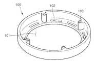
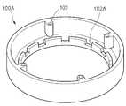
도 9는 상기 가이드부재(100)의 사시도이고, 도 10은 상기 가이드부재(100)의 평면도이다.9 is a perspective view of the
도 4, 도 9 및 도 10을 참조하면, 상기 가이드부재(100)는 상기 발광모듈부(130)가 노출되는 개구부(101), 내측과 외측 사이에 다수의 제1 방열홀(102) 및 상기 방열몸체(150)와 결합되는 체결홈(103)을 포함할 수 있다.4, 9 and 10, the
상기 가이드부재(100)는 원형의 링(ring) 형태로 도시되었으나, 다각형, 타원형의 링 형태를 가질 수도 있으며, 이에 대해 한정하지는 않는다.The
상기 개구부(101)를 통해 상기 발광모듈부(130)의 하나 또는 복수의 발광 소자(131)들이 노출되게 된다. 다만, 상기 가이드부재(100)는 상기 발광모듈부(130)를 상기 제2 수납홈(152)에 압착하는 작용을 하므로, 상기 개구부(101)의 폭은 상기 발광모듈부(130)의 폭보다는 작은 것이 바람직하다.One or a plurality of
구체적으로 설명하면, 상기 가이드부재(100)를 상기 방열몸체(150)에 결합시킴에 따라, 상기 가이드부재(100)는 상기 렌즈(110), 제1 보호링(120) 및 상기 발광모듈부(130)의 둘레 영역에 압력을 가하여, 상기 렌즈(110), 제1 보호링(120) 및 상기 발광모듈부(130)를 상기 방열몸체(150)의 제2 수납홈(152)에 견고히 고정시킬 수 있으므로, 상기 조명 장치(1)의 신뢰성이 향상될 수 있다.Specifically, as the
상기 체결홈(103)은 상기 가이드부재(100)를 상기 방열몸체(150)에 결합시킬 수 있다. 예를 들어, 도 4에 도시된 것처럼, 상기 방열몸체(150)의 제1 체결부재(154)의 홀과 상기 가이드부재(100)의 상기 체결홈(103)을 대향시킨 후, 상기 제1 체결부재(154)의 홀 및 상기 체결홈(103)에 나사를 삽입함으로써 상기 가이드부재(100) 및 상기 방열몸체(150)를 결합시킬 수 있으나, 이에 대해 한정하지는 않는다.The
한편, 상기 조명 장치(1)의 전원제어부(160), 발광모듈부(130) 등의 내부 부품의 교체가 필요한 경우, 상기 가이드부재(100)는 상기 방열몸체(150)에서 용이하게 분리될 수 있으므로, 사용자 등이 용이하게 상기 조명 장치(1)의 유지 보수를 실시할 수 있다.On the other hand, when the internal parts such as the
상기 다수의 제1 방열홀(102)은 상기 가이드부재(100)의 내측과 외측 사이에 형성되며, 상기 다수의 제1 방열홀(102)은 상기 조명 장치(1) 내부의 공기 흐름을 원활하게 함으로써 방열 효율을 극대화할 수 있다. 이하, 이에 대해 설명한다.The plurality of first heat dissipation holes 102 are formed between the inside and the outside of the
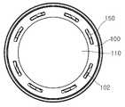
도 11은 실시예에 따른 조명 장치(1)의 하부 영역을 나타내는 확대 단면도이고, 도 12는 상기 조명 장치(1)의 하면도이고, 도 13은 상기 조명 장치(1)의 상면도이다.11 is an enlarged cross-sectional view showing a lower region of the
도 11 내지 도 13을 참조하면, 상기 다수의 제1 방열홀(102)을 통해 상기 조명 장치(1) 내부로 유입된 공기(AIR)는 상기 방열몸체(150) 측면의 요 구조(b) 및 철 구조(a)로 흐르게 된다. 그리고, 공기 대류 원리에 의해, 상기 방열몸체(150)의 요철 구조 사이를 통과하여 데워진 공기(AIR)는 상기 내부 케이스(170)와 상기 외 부 케이스(180) 사이에 형성된 다수의 통풍홀(182)을 통해 빠져나갈 수 있다. 또는, 상기 다수의 통풍홀(182)로 유입된 공기가 상기 다수의 제1 방열홀(102)을 통해 빠져나갈 수도 있으며, 이에 대해 한정하지는 않는다.11 to 13, the air (AIR) introduced into the
즉, 상기 다수의 제1 방열홀(102) 및 상기 다수의 통풍홀(182)에 의해 공기 대류 원리를 이용한 방열이 가능해지므로, 상기 조명 장치(1)의 방열 효율을 극대화시킬 수 있게 된다.That is, since the plurality of first heat dissipation holes 102 and the plurality of
한편, 상기 가이드부재(100)의 공기 유입 구조의 형태는 이에 한정되지는 않으며, 다양하게 변형될 수 있다. 예를 들어, 도 14에 도시된 것처럼, 다른 실시예에 따른 가이드부재(100A)는 내측면이 요철 구조를 가지도록 형성되어, 요 구조(102A)를 통해 공기(AIR)가 유입될 수도 있다.On the other hand, the shape of the air inlet structure of the
<렌즈(110)><
도 4 및 도 11을 참조하면, 상기 렌즈(110)는 상기 발광모듈부(130) 아래에 형성되어 상기 발광모듈부(130)에서 방출되는 빛의 배광을 조절한다.4 and 11, the
상기 렌즈(110)는 다양한 형상을 가질 수 있는데, 예를 들어, 상기 렌즈(110)는 파라볼라 형태의 렌즈, 프레넬 렌즈, 볼록 렌즈 또는 오목 렌즈 중 적어도 하나를 포함할 수 있다.The
상기 렌즈(110)는 상기 발광모듈부(130) 아래에 제1 거리(h) 이격되도록 배치될 수 있으며, 상기 제1 거리(h)는 상기 조명 장치(1)의 설계에 따라 0mm 내지 50mm일 수 있다. 다만, 이에 대해 한정하지는 않는다.The
상기 제1 거리(h)는 상기 발광모듈부(130)와 상기 렌즈(110) 사이에 배치되는 상기 제1 보호링(120)에 의해 유지될 수 있다. 또는, 상기 방열몸체(150)의 제2 수납홈(152)에 상기 렌즈(110)를 지지할 수 있는 별도의 지지부를 형성함으로써, 상기 발광모듈부(130)와 상기 렌즈(110) 사이에 상기 제1 거리(h)가 유지될 수도 있으며, 이에 대해 한정하지는 않는다.The first distance h may be maintained by the
또한, 상기 렌즈(110)는 상기 가이드부재(100)에 의해 고정될 수 있다. 즉, 상기 가이드부재(100)의 내측면은 상기 렌즈(110)와 접촉하며, 상기 가이드부재(100)의 내측면에 의해 상기 렌즈(110) 및 상기 발광모듈부(130)는 상기 방열몸체(150)의 제2 수납홈(152)에 압착되어 고정되게 된다.In addition, the
상기 렌즈(110)는 유리, PMMA(Polymethylmethacrylate), PC(Polycarbornate) 등의 재질로 형성될 수 있다.The
또한, 상기 조명 장치(1)의 설계에 따라, 상기 렌즈(110)는 형광체를 포함하도록 형성되거나, 상기 렌즈(110)의 입사면 또는 출사면에 형광체를 포함하는 광여기 필름(PLF:Photo Luminescent Film)이 부착될 수도 있다. 상기 형광체에 의해 상기 발광모듈부(130)에서 방출되는 광은 파장이 변화되어 출사되게 된다.In addition, according to the design of the
<내부 케이스(170)><
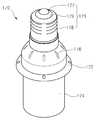
도 15는 상기 내부 케이스(170)의 사시도이다.15 is a perspective view of the
도 4 및 도 15를 참조하면, 상기 내부 케이스(170)는 상기 방열몸체(150)의 상기 제1 수납홈(151)에 삽입되는 삽입부(174), 외부 전원과 전기적으로 연결되는 연결 단자(175) 및 상기 외부 케이스(180)와 결합되는 제2 체결부재(172)를 포함할 수 있다.4 and 15, the
상기 내부 케이스(170)는 절연성 및 내구성이 뛰어난 재질로 형성될 수 있으며, 예를 들어, 수지 재질로 형성될 수 있다.The
상기 삽입부(174)는 상기 내부 케이스(170)의 하부 영역에 형성되며, 상기 삽입부(174)의 측벽은 상기 제1 수납홈(151)에 삽입되어 상기 전원제어부(160)와 상기 방열몸체(150) 사이의 전기적 쇼트 등을 방지함으로써 상기 조명 장치(1)의 내전압을 향상시킬 수 있다.The
상기 연결 단자(175)는 예를 들어, 소켓(socket) 방식으로 외부 전원에 연결될 수 있다. 즉, 상기 연결 단자(175)는 정점에 제1 전극(177), 측면부에 제2 전극(182) 및 상기 제1 전극(177) 및 제2 전극(182) 사이로 절연부재(179)를 포함할 수 있으며, 상기 제1,2 전극(177)은 외부 전원에 의해 전원을 제공받을 수 있다. 다만, 상기 연결 단자(175)의 형태는 상기 조명 장치(1)의 설계에 따라 다양하게 변형될 수 있으므로, 이에 대해 한정하지는 않는다.The
상기 제2 체결부재(172)는 상기 내부 케이스(170)의 측면에 형성되어 다수의 홀을 포함할 수 있으며, 상기 다수의 홀에 나사 등이 삽입되어 상기 내부 케이스(170)와 상기 외부 케이스(180)를 결합시킬 수 있다.The
또한, 상기 내부 케이스(170)에는 다수의 제2 방열홀(176)이 형성되어, 상기 내부 케이스(170) 내부의 방열 효율을 향상시킬 수 있다.In addition, a plurality of second heat dissipation holes 176 are formed in the
<전원제어부(160) 및 내부 케이스(170)의 내부 구조><Internal Structure of Power
도 4를 참조하면, 상기 전원제어부(160)는 상기 방열몸체(150)의 제1 수납홈(151)에 배치될 수 있다.Referring to FIG. 4, the
상기 전원제어부(160)는 지지기판(161)과, 상기 지지기판(161) 상에 탑재되는 다수의 부품(162)을 포함할 수 있는데, 상기 다수의 부품(162)은 예를 들어, 외부 전원으로부터 제공되는 교류 전원을 직류 전원으로 변환하는 직류변환장치, 상기 발광모듈부(130)의 구동을 제어하는 구동칩, 상기 발광모듈부(130)을 보호하기 위한 ESD(ElectroStatic discharge) 보호 소자 등을 포함할 수 있으나 이에 대해 한정하지는 않는다.The
이때, 도시된 바와 같이, 상기 지지기판(161)은 상기 내부 케이스(170) 내의 공기 흐름을 원활히 하기 위해 수직 방향으로 세워져 배치될 수 있다. 따라서, 상기 지지기판(161)이 수평 방향으로 배치되는 경우에 비해, 상기 내부 케이스(170) 내부에 상하 방향으로 대류 현상에 의한 공기 흐름이 발생할 수 있게 되므로, 상기 조명 장치(1)의 방열 효율이 향상될 수 있다.At this time, as shown, the
한편, 상기 지지기판(161)은 상기 내부 케이스(170) 내에 수평 방향으로 배치될 수도 있으며, 이에 대해 한정하지는 않는다.On the other hand, the
상기 전원제어부(160)는 상기 내부 케이스(170)의 연결 단자(175) 및 상기 발광모듈부(130)와 각각 제1 배선(164) 및 제2 배선(165)에 의해 전기적으로 연결될 수 있다.The
구체적으로는, 상기 제1 배선(164)은 상기 연결단자(175)의 제1 전극(177) 및 제2 전극(182)과 연결되어, 외부 전원으로부터 전원을 공급받을 수 있다.In detail, the
또한, 상기 제2 배선(165)은 상기 방열몸체(150)의 관통홀(153)을 통과하여 상기 전원제어부(160) 및 상기 발광모듈부(130)를 서로 전기적으로 연결할 수 있다.In addition, the
그런데, 상기 지지기판(161)이 상기 내부 케이스(170) 내에 수직 방향으로 세워져 배치되므로, 상기 조명 장치(1)를 장시간 사용하는 경우 상기 제2 배선(165)이 상기 지지기판(161)에 눌려 손상되는 문제가 발생할 수 있다.However, since the
따라서, 실시예에서는, 도 16에 도시된 것처럼 상기 방열몸체(150)의 바닥면에 상기 관통홀(153)의 주위로 돌출부(159)를 형성하여, 상기 지지기판(161)을 지지하는 동시에 상기 제2 배선(165)의 손상을 미연에 방지할 수 있다.Therefore, in the embodiment, as shown in FIG. 16, the
<외부 케이스(180)><
상기 외부 케이스(180)는 상기 내부 케이스(170)와 결합되어 상기 방열몸체(150), 발광모듈부(130), 전원제어부(160) 등을 수납하고, 상기 조명 장치(1)의 외관을 이룰 수 있다.The
상기 외부 케이스(180)에 의해 상기 방열몸체(150)가 노출되지 않으므로 화상 사고 및 감전 사고를 방지될 수 있으며, 사용자가 상기 조명 장치(1)를 용이하게 취급할 수 있다. 이하, 상기 외부 케이스(180)에 대해 상세히 설명한다.Since the
도 17은 상기 외부 케이스(180)의 사시도이다.17 is a perspective view of the
도 17을 참조하면, 상기 외부 케이스(180)는 상기 내부 케이스(170) 등이 삽 입되는 개구부(181)와, 상기 내부 케이스(170)의 제2 체결부재(172)와 결합되는 결합홈(183)과, 상기 조명 장치 내에 공기를 유입 또는 방출하는 상기 다수의 통풍홀(182)을 포함할 수 있다.Referring to FIG. 17, the
상기 외부 케이스(180)는 절연성 및 내구성이 뛰어난 재질로 형성될 수 있으며, 예를 들어, 수지 재질로 형성될 수 있다.The
상기 외부 케이스(180)의 상기 개구부(181)로 상기 내부 케이스(170)가 삽입되고, 상기 결합홈(183) 및 상기 내부 케이스(170)의 제2 체결부재(172)를 나사 등에 의해 서로 결합함으로써, 상기 외부 케이스(180) 및 상기 내부 케이스(170)가 서로 결합될 수 있다.The
상기 다수의 통풍홀(182)은 앞에서 설명한 것처럼, 상기 가이드부재(100)의 다수의 제1 방열홀(102)과 함께 상기 조명 장치(1) 내의 원활한 공기 흐름을 가능하게 하여 상기 조명 장치(1)의 방열 효율을 향상시킬 수 있다.As described above, the plurality of
도시된 것처럼, 상기 다수의 통풍홀(182)은 상기 외부 케이스(180)의 상면의 둘레 영역에 형성될 수 있으며, 부채꼴의 호 형상을 가질 수 있으나, 이에 대해 한정하지는 않는다. 또한, 상기 결합홈(183)은 상기 다수의 통풍홀(182)들 사이에 형성될 수 있다.As shown, the plurality of
한편, 상기 외부 케이스(180)의 측면에는 방열 효율을 향상시키기 위한 다수의 홀(184) 및 상기 조명 장치(1)의 취급을 용이하게 하기 위한 마킹홈(185) 중 적어도 하나가 형성될 수 있다. 다만, 상기 다수의 홀(184) 및 상기 마킹홈(185)은 형성되지 않을 수도 있으며, 이에 대해 한정하지는 않는다.Meanwhile, at least one of a plurality of
이상에서 실시예들에 설명된 특징, 구조, 효과 등은 본 발명의 적어도 하나의 실시예에 포함되며, 반드시 하나의 실시예에만 한정되는 것은 아니다. 나아가, 각 실시예에서 예시된 특징, 구조, 효과 등은 실시예들이 속하는 분야의 통상의 지식을 가지는 자에 의해 다른 실시예들에 대해서도 조합 또는 변형되어 실시 가능하다. 따라서 이러한 조합과 변형에 관계된 내용들은 본 발명의 범위에 포함되는 것으로 해석되어야 할 것이다.Features, structures, effects, and the like described in the above embodiments are included in at least one embodiment of the present invention, and are not necessarily limited to only one embodiment. Furthermore, the features, structures, effects, and the like illustrated in each embodiment may be combined or modified with respect to other embodiments by those skilled in the art to which the embodiments belong. Therefore, it should be understood that the present invention is not limited to these combinations and modifications.
또한, 이상에서 실시예를 중심으로 설명하였으나 이는 단지 예시일 뿐 본 발명을 한정하는 것이 아니며, 본 발명이 속하는 분야의 통상의 지식을 가진 자라면 본 실시예의 본질적인 특성을 벗어나지 않는 범위에서 이상에 예시되지 않은 여러 가지의 변형과 응용이 가능함을 알 수 있을 것이다. 예를 들어, 실시예에 구체적으로 나타난 각 구성 요소는 변형하여 실시할 수 있는 것이다. 그리고 이러한 변형과 응용에 관계된 차이점들은 첨부된 청구 범위에서 규정하는 본 발명의 범위에 포함되는 것으로 해석되어야 할 것이다.In addition, the above description has been made with reference to the embodiment, which is merely an example, and is not intended to limit the present invention. Those skilled in the art to which the present invention pertains will be illustrated as above without departing from the essential characteristics of the present embodiment. It will be appreciated that various modifications and applications are possible. For example, each component specifically shown in the embodiment can be modified. And differences relating to such modifications and applications will have to be construed as being included in the scope of the invention defined in the appended claims.
도 1은 실시예에 따른 조명 장치를 아래 방향에서 바라본 사시도1 is a perspective view of a lighting device according to an embodiment as viewed from below;
도 2는 도 1의 조명 장치를 윗 방향에서 바라본 사시도FIG. 2 is a perspective view of the lighting device of FIG. 1 viewed from above. FIG.
도 3은 도 1의 조명 장치의 분해 사시도3 is an exploded perspective view of the lighting apparatus of FIG.
도 4는 도 1의 조명 장치의 단면을 나타내는 도면4 shows a cross section of the lighting device of FIG. 1;
도 5는 도 1의 조명 장치의 방열몸체의 사시도5 is a perspective view of a heat dissipating body of the lighting apparatus of FIG.
도 6은 도 5의 A-A' 단면을 나타내는 단면도6 is a cross-sectional view taken along the line AA ′ of FIG. 5.
도 7은 도 1의 조명 장치의 발광모듈부 및 제1 보호링의 결합 사시도7 is a perspective view of a combination of the light emitting module unit and the first protective ring of the lighting device of FIG.
도 8은 도 7의 B-B' 단면을 나타내는 단면도FIG. 8 is a sectional view taken along the line B-B 'of FIG.
도 9는 도 1의 조명 장치의 가이드부재의 사시도9 is a perspective view of a guide member of the lighting apparatus of FIG.
도 10은 도 9의 가이드부재의 평면도10 is a plan view of the guide member of FIG.
도 11은 도 1의 조명 장치의 하부 영역을 나타내는 확대 단면도11 is an enlarged cross-sectional view showing a lower region of the lighting device of FIG.
도 12는 도 1의 조명 장치의 하면도12 is a bottom view of the lighting device of FIG.
도 13은 도 1의 조명 장치의 상면도FIG. 13 is a top view of the lighting device of FIG. 1. FIG.
도 14는 다른 실시예에 따른 조명 장치의 가이드부재의 사시도14 is a perspective view of a guide member of a lighting apparatus according to another embodiment
도 15는 도 1의 조명 장치의 내부 케이스의 사시도15 is a perspective view of an inner case of the lighting device of FIG.
도 16에 다른 실시예에 따른 조명 장치의 방열몸체를 나타내는 도면16 is a view showing a heat dissipation body of the lighting apparatus according to another embodiment
도 17은 도 1의 조명 장치의 외부 케이스의 사시도17 is a perspective view of an outer case of the lighting device of FIG.
Claims (20)
Translated fromKoreanPriority Applications (1)
| Application Number | Priority Date | Filing Date | Title |
|---|---|---|---|
| KR1020090107500AKR101072060B1 (en) | 2009-11-09 | 2009-11-09 | Lighting device |
Applications Claiming Priority (1)
| Application Number | Priority Date | Filing Date | Title |
|---|---|---|---|
| KR1020090107500AKR101072060B1 (en) | 2009-11-09 | 2009-11-09 | Lighting device |
Publications (2)
| Publication Number | Publication Date |
|---|---|
| KR20110050913A KR20110050913A (en) | 2011-05-17 |
| KR101072060B1true KR101072060B1 (en) | 2011-10-10 |
Family
ID=44361372
Family Applications (1)
| Application Number | Title | Priority Date | Filing Date |
|---|---|---|---|
| KR1020090107500AExpired - Fee RelatedKR101072060B1 (en) | 2009-11-09 | 2009-11-09 | Lighting device |
Country Status (1)
| Country | Link |
|---|---|
| KR (1) | KR101072060B1 (en) |
Cited By (1)
| Publication number | Priority date | Publication date | Assignee | Title |
|---|---|---|---|---|
| KR101609536B1 (en) | 2013-10-04 | 2016-04-06 | 주식회사 에스티큐브 | Led lamp including filter for improving color rendering property of led and improving method of color rendering property for led using the same |
Families Citing this family (1)
| Publication number | Priority date | Publication date | Assignee | Title |
|---|---|---|---|---|
| KR101883323B1 (en)* | 2011-08-30 | 2018-07-30 | 엘지이노텍 주식회사 | Lighting device |
Citations (1)
| Publication number | Priority date | Publication date | Assignee | Title |
|---|---|---|---|---|
| KR100898817B1 (en)* | 2007-03-30 | 2009-05-22 | 한국광기술원 | Light emitting diode bulb capable of heat dissipation |
- 2009
- 2009-11-09KRKR1020090107500Apatent/KR101072060B1/ennot_activeExpired - Fee Related
Patent Citations (1)
| Publication number | Priority date | Publication date | Assignee | Title |
|---|---|---|---|---|
| KR100898817B1 (en)* | 2007-03-30 | 2009-05-22 | 한국광기술원 | Light emitting diode bulb capable of heat dissipation |
Cited By (1)
| Publication number | Priority date | Publication date | Assignee | Title |
|---|---|---|---|---|
| KR101609536B1 (en) | 2013-10-04 | 2016-04-06 | 주식회사 에스티큐브 | Led lamp including filter for improving color rendering property of led and improving method of color rendering property for led using the same |
Also Published As
| Publication number | Publication date |
|---|---|
| KR20110050913A (en) | 2011-05-17 |
Similar Documents
| Publication | Publication Date | Title |
|---|---|---|
| JP5736151B2 (en) | Lighting device | |
| JP5663273B2 (en) | Lighting device | |
| US8911110B2 (en) | Lighting device | |
| JP6285102B2 (en) | Lighting device | |
| KR101081312B1 (en) | Lighting device | |
| KR101072060B1 (en) | Lighting device | |
| KR101072168B1 (en) | Lighting device | |
| KR101103518B1 (en) | Lighting device | |
| KR101091394B1 (en) | Lighting device | |
| KR101090983B1 (en) | Lighting device | |
| KR101080697B1 (en) | Lighting device | |
| KR101610318B1 (en) | Lighting device | |
| KR20130084395A (en) | Lighting device | |
| KR101137890B1 (en) | LED illumination Lamp | |
| KR101137432B1 (en) | LED illumination Lamp | |
| KR101304874B1 (en) | Lighting device | |
| KR101145167B1 (en) | Led fluorescent lamp | |
| KR101040318B1 (en) | Lighting device | |
| KR101113610B1 (en) | Lighting device | |
| KR101977649B1 (en) | Lighting device | |
| KR101976469B1 (en) | Lighting device | |
| KR101090727B1 (en) | Lighting device | |
| KR20120057590A (en) | Lighting device |
Legal Events
| Date | Code | Title | Description |
|---|---|---|---|
| A201 | Request for examination | ||
| PA0109 | Patent application | St.27 status event code:A-0-1-A10-A12-nap-PA0109 | |
| PA0201 | Request for examination | St.27 status event code:A-1-2-D10-D11-exm-PA0201 | |
| P11-X000 | Amendment of application requested | St.27 status event code:A-2-2-P10-P11-nap-X000 | |
| P13-X000 | Application amended | St.27 status event code:A-2-2-P10-P13-nap-X000 | |
| R15-X000 | Change to inventor requested | St.27 status event code:A-3-3-R10-R15-oth-X000 | |
| R16-X000 | Change to inventor recorded | St.27 status event code:A-3-3-R10-R16-oth-X000 | |
| R18-X000 | Changes to party contact information recorded | St.27 status event code:A-3-3-R10-R18-oth-X000 | |
| E902 | Notification of reason for refusal | ||
| PE0902 | Notice of grounds for rejection | St.27 status event code:A-1-2-D10-D21-exm-PE0902 | |
| E13-X000 | Pre-grant limitation requested | St.27 status event code:A-2-3-E10-E13-lim-X000 | |
| P11-X000 | Amendment of application requested | St.27 status event code:A-2-2-P10-P11-nap-X000 | |
| P13-X000 | Application amended | St.27 status event code:A-2-2-P10-P13-nap-X000 | |
| PG1501 | Laying open of application | St.27 status event code:A-1-1-Q10-Q12-nap-PG1501 | |
| E701 | Decision to grant or registration of patent right | ||
| PE0701 | Decision of registration | St.27 status event code:A-1-2-D10-D22-exm-PE0701 | |
| GRNT | Written decision to grant | ||
| PR0701 | Registration of establishment | St.27 status event code:A-2-4-F10-F11-exm-PR0701 | |
| PR1002 | Payment of registration fee | St.27 status event code:A-2-2-U10-U11-oth-PR1002 Fee payment year number:1 | |
| PG1601 | Publication of registration | St.27 status event code:A-4-4-Q10-Q13-nap-PG1601 | |
| PR1001 | Payment of annual fee | St.27 status event code:A-4-4-U10-U11-oth-PR1001 Fee payment year number:4 | |
| PN2301 | Change of applicant | St.27 status event code:A-5-5-R10-R13-asn-PN2301 St.27 status event code:A-5-5-R10-R11-asn-PN2301 | |
| FPAY | Annual fee payment | Payment date:20150904 Year of fee payment:5 | |
| PR1001 | Payment of annual fee | St.27 status event code:A-4-4-U10-U11-oth-PR1001 Fee payment year number:5 | |
| P22-X000 | Classification modified | St.27 status event code:A-4-4-P10-P22-nap-X000 | |
| FPAY | Annual fee payment | Payment date:20160905 Year of fee payment:6 | |
| PR1001 | Payment of annual fee | St.27 status event code:A-4-4-U10-U11-oth-PR1001 Fee payment year number:6 | |
| R18-X000 | Changes to party contact information recorded | St.27 status event code:A-5-5-R10-R18-oth-X000 | |
| FPAY | Annual fee payment | Payment date:20170905 Year of fee payment:7 | |
| PR1001 | Payment of annual fee | St.27 status event code:A-4-4-U10-U11-oth-PR1001 Fee payment year number:7 | |
| R18-X000 | Changes to party contact information recorded | St.27 status event code:A-5-5-R10-R18-oth-X000 | |
| FPAY | Annual fee payment | Payment date:20180910 Year of fee payment:8 | |
| PR1001 | Payment of annual fee | St.27 status event code:A-4-4-U10-U11-oth-PR1001 Fee payment year number:8 | |
| P22-X000 | Classification modified | St.27 status event code:A-4-4-P10-P22-nap-X000 | |
| FPAY | Annual fee payment | Payment date:20190916 Year of fee payment:9 | |
| PR1001 | Payment of annual fee | St.27 status event code:A-4-4-U10-U11-oth-PR1001 Fee payment year number:9 | |
| R18-X000 | Changes to party contact information recorded | St.27 status event code:A-5-5-R10-R18-oth-X000 | |
| PR1001 | Payment of annual fee | St.27 status event code:A-4-4-U10-U11-oth-PR1001 Fee payment year number:10 | |
| PN2301 | Change of applicant | St.27 status event code:A-5-5-R10-R13-asn-PN2301 St.27 status event code:A-5-5-R10-R11-asn-PN2301 | |
| PN2301 | Change of applicant | St.27 status event code:A-5-5-R10-R11-asn-PN2301 | |
| PN2301 | Change of applicant | St.27 status event code:A-5-5-R10-R14-asn-PN2301 | |
| PR1001 | Payment of annual fee | St.27 status event code:A-4-4-U10-U11-oth-PR1001 Fee payment year number:11 | |
| PR1001 | Payment of annual fee | St.27 status event code:A-4-4-U10-U11-oth-PR1001 Fee payment year number:12 | |
| PC1903 | Unpaid annual fee | St.27 status event code:A-4-4-U10-U13-oth-PC1903 Not in force date:20231005 Payment event data comment text:Termination Category : DEFAULT_OF_REGISTRATION_FEE | |
| PC1903 | Unpaid annual fee | St.27 status event code:N-4-6-H10-H13-oth-PC1903 Ip right cessation event data comment text:Termination Category : DEFAULT_OF_REGISTRATION_FEE Not in force date:20231005 |