KR101070695B1 - Electronic Endoscope for providing 3D image data - Google Patents
Electronic Endoscope for providing 3D image dataDownload PDFInfo
- Publication number
- KR101070695B1 KR101070695B1KR1020100023253AKR20100023253AKR101070695B1KR 101070695 B1KR101070695 B1KR 101070695B1KR 1020100023253 AKR1020100023253 AKR 1020100023253AKR 20100023253 AKR20100023253 AKR 20100023253AKR 101070695 B1KR101070695 B1KR 101070695B1
- Authority
- KR
- South Korea
- Prior art keywords
- image data
- rod
- endoscope
- providing
- photographing
- Prior art date
- Legal status (The legal status is an assumption and is not a legal conclusion. Google has not performed a legal analysis and makes no representation as to the accuracy of the status listed.)
- Expired - Fee Related
Links
Images


Classifications
- A—HUMAN NECESSITIES
- A61—MEDICAL OR VETERINARY SCIENCE; HYGIENE
- A61B—DIAGNOSIS; SURGERY; IDENTIFICATION
- A61B1/00—Instruments for performing medical examinations of the interior of cavities or tubes of the body by visual or photographical inspection, e.g. endoscopes; Illuminating arrangements therefor
- A61B1/04—Instruments for performing medical examinations of the interior of cavities or tubes of the body by visual or photographical inspection, e.g. endoscopes; Illuminating arrangements therefor combined with photographic or television appliances
- A61B1/05—Instruments for performing medical examinations of the interior of cavities or tubes of the body by visual or photographical inspection, e.g. endoscopes; Illuminating arrangements therefor combined with photographic or television appliances characterised by the image sensor, e.g. camera, being in the distal end portion
- A—HUMAN NECESSITIES
- A61—MEDICAL OR VETERINARY SCIENCE; HYGIENE
- A61B—DIAGNOSIS; SURGERY; IDENTIFICATION
- A61B1/00—Instruments for performing medical examinations of the interior of cavities or tubes of the body by visual or photographical inspection, e.g. endoscopes; Illuminating arrangements therefor
- A61B1/00064—Constructional details of the endoscope body
- A61B1/00071—Insertion part of the endoscope body
- A61B1/0008—Insertion part of the endoscope body characterised by distal tip features
- A61B1/00096—Optical elements
- A—HUMAN NECESSITIES
- A61—MEDICAL OR VETERINARY SCIENCE; HYGIENE
- A61B—DIAGNOSIS; SURGERY; IDENTIFICATION
- A61B1/00—Instruments for performing medical examinations of the interior of cavities or tubes of the body by visual or photographical inspection, e.g. endoscopes; Illuminating arrangements therefor
- A61B1/00163—Optical arrangements
- A61B1/00194—Optical arrangements adapted for three-dimensional imaging
- A—HUMAN NECESSITIES
- A61—MEDICAL OR VETERINARY SCIENCE; HYGIENE
- A61B—DIAGNOSIS; SURGERY; IDENTIFICATION
- A61B1/00—Instruments for performing medical examinations of the interior of cavities or tubes of the body by visual or photographical inspection, e.g. endoscopes; Illuminating arrangements therefor
- A61B1/06—Instruments for performing medical examinations of the interior of cavities or tubes of the body by visual or photographical inspection, e.g. endoscopes; Illuminating arrangements therefor with illuminating arrangements
- A61B1/0661—Endoscope light sources
- A61B1/0676—Endoscope light sources at distal tip of an endoscope
- A—HUMAN NECESSITIES
- A61—MEDICAL OR VETERINARY SCIENCE; HYGIENE
- A61B—DIAGNOSIS; SURGERY; IDENTIFICATION
- A61B1/00—Instruments for performing medical examinations of the interior of cavities or tubes of the body by visual or photographical inspection, e.g. endoscopes; Illuminating arrangements therefor
- A61B1/06—Instruments for performing medical examinations of the interior of cavities or tubes of the body by visual or photographical inspection, e.g. endoscopes; Illuminating arrangements therefor with illuminating arrangements
- A61B1/0661—Endoscope light sources
- A61B1/0684—Endoscope light sources using light emitting diodes [LED]
Landscapes
- Health & Medical Sciences (AREA)
- Life Sciences & Earth Sciences (AREA)
- Surgery (AREA)
- Physics & Mathematics (AREA)
- Engineering & Computer Science (AREA)
- Optics & Photonics (AREA)
- Biomedical Technology (AREA)
- Molecular Biology (AREA)
- Pathology (AREA)
- Nuclear Medicine, Radiotherapy & Molecular Imaging (AREA)
- Biophysics (AREA)
- Heart & Thoracic Surgery (AREA)
- Medical Informatics (AREA)
- Radiology & Medical Imaging (AREA)
- Animal Behavior & Ethology (AREA)
- General Health & Medical Sciences (AREA)
- Public Health (AREA)
- Veterinary Medicine (AREA)
- Microelectronics & Electronic Packaging (AREA)
- Endoscopes (AREA)
- Instruments For Viewing The Inside Of Hollow Bodies (AREA)
Abstract
Translated fromKoreanDescription
Translated fromKorean본 발명은 3차원 영상데이터를 제공하는 전자 내시경에 관한 것으로서, 더 상세하게는 한 쌍의 촬상소자를 통하여 입체적인 화면을 제공하되, 수술시 최소의 절개가 가능한 3차원 영상데이터를 제공하는 전자 내시경에 관한 것이다.
The present invention relates to an electronic endoscope for providing three-dimensional image data, and more particularly to an electronic endoscope that provides a three-dimensional screen through a pair of imaging devices, providing a three-dimensional image data that can be minimally incision during surgery It is about.
일반적으로 내시경은 직달경(直達鏡)이라 하여 하나의 통(筒)으로 되어 있는대, 치료와 진단을 목적으로 인체내부를 관찰하기 위해 환자의 체내에 삽입(체내에 삽입하는 예로는 구강을 통하여 삽입을 할 수도 있으며, 수술부위를 절개하고 절개한 곳에 삽입할 수 있다. 편의상, 후자를 예를 들어 설명하기로 한다.)하여 의사가 환자의 장기를 직접 육안으로 보며 치료할 경우에 사용하게 된다.
In general, an endoscope is a straight tube, which is a single tube. It is inserted into the patient's body to observe the inside of the human body for treatment and diagnosis. It may be inserted, or the surgical site may be incised and inserted into the incision.For convenience, the latter will be described as an example.) It is used when the doctor treats the patient's organs with the naked eye.
그러나, 상기와 같은 하나의 통으로 되어 있는 내시경은 2D(2차원, 평면)화면을 제공하여 입체감이 떨어지므로, 정교한 수술시에 환자의 치료부위(환부)에 정밀한 접근이 어려운 문제점이 있었다.
However, since the endoscope consisting of a single tube as described above provides a 2D (two-dimensional, planar) screen, the stereoscopic feeling is reduced, and thus, there is a problem that it is difficult to precisely access the treatment area (affected area) of the patient during a sophisticated surgery.
이러한 2D 화면이 제공되는 내시경에 대한 해결책으로서, 본 출원인이 2007.9.20에 '3차원 영상데이터를 제공하는 내시경'(출원번호 10-2007-0096119호)을 출원한 바 있다. 상기 내시경은, 도 1에 도시된 바와 같이, 환자의 체내에 삽입되어 영상정보를 제공하는 내시경에 있어서, 상기 내시경전면부에 평행하게 설치되는 한쌍의 렌즈; 상기 한쌍의 렌즈의 후면에 각각 위치하여 렌즈에 맺힌 상을 촬영하는 한쌍의 CCD 카메라; 상기 내시경전면부에 위치하여 환부에 빛을 조사하는 광조사부;를 포함하는 것을 특징으로 한다.
As a solution to an endoscope provided with such a 2D screen, the applicant has applied for an 'endoscope for providing three-dimensional image data' (Application No. 10-2007-0096119) on September 20, 2007. The endoscope, as shown in Figure 1, in the endoscope to be inserted into the body of the patient to provide the image information, a pair of lenses installed parallel to the front endoscope portion; A pair of CCD cameras positioned on the rear surfaces of the pair of lenses to photograph an image formed on the lens; It is located in the endoscope front surface portion for irradiating light to the affected part; characterized in that it comprises a.
그러나 상기 '3차원 영상데이터를 제공하는 내시경'을 이용하여 수술할 때에는 두 개의 로드렌즈 열이 복부로 삽입(즉, 2개의 카메라가 삽입)되어야 하므로, 하나의 로드렌즈 열이 삽입될 때보다 훨씬 많이 절개를 하여야 한다. 한편, 복부절개를 최소화하는 경우(12mm 정도)에는, 양안(兩眼)간의 간격이 너무 좁아 촛점을 맞추기가 어려운 문제점이 발생한다.
However, when operating with the 'endoscope providing 3D image data', two rod lens rows should be inserted into the abdomen (that is, two cameras are inserted), which is far more than when one rod lens row is inserted. You have to make a lot of incisions. On the other hand, when the abdominal incision is minimized (about 12 mm), a problem arises that it is difficult to focus because the distance between both eyes is too narrow.
본 발명은 상술한 문제점을 해결하고자 안출된 것으로서, 선단부 내부에 수납되어 있다가 각각 팝업(pop-up)식으로 돌출되어 전개가 가능한 한쌍의 촬상소자를 이용하여 입체적인 화면을 제공함에도 불구하고, 체내에 삽입시에 최소한의 삽입공간이 필요하게 되는(수술부위의 절개를 최소화할 수 있는) 3차원 영상데이터를 제공하는 전자 내시경을 제공하는 것이다.
SUMMARY OF THE INVENTION The present invention has been made to solve the above-mentioned problems, and despite being provided in a tip portion and protruding in a pop-up manner, respectively, to provide a three-dimensional screen using a pair of image pickup devices, To provide an electronic endoscope that provides three-dimensional image data (minimizing the incision of the surgical site) that requires a minimum insertion space when inserted into the.
상기한 과제를 해결하기 위하여 본 발명의 3차원 영상데이터를 제공하는 전자 내시경(100)은 환자의 체내에 삽입되어 영상정보를 제공하는 관형상의 몸체(130)를 가지는 내시경에 있어서, 상기 관형상의 몸체(130)는, 전단이 개방되어 있는 선단부(110)와, 상기 선단부(110)에 연결되며, 상기 선단부(110)가 환자의 체내에 삽입되면 구부러지는 절곡부(120)와, 상기 선단부(110)의 내부 일측면에 설치되고, 하단에 연결된 제 1 작동 로드(142)의 작동에 연동하여 상하 방향 및 회전 방향의 작동이 가능하며, 촬영소자(141)가 전면에 설치되어 있는 제 1 촬영부(140)와, 상기 선단부(110)의 내부 타측면에 설치되고, 하단에 연결된 제 2 작동 로드(151)의 작동에 연동하여 상하 방향 및 회전 방향의 작동이 가능하며, 촬영소자(141)가 전면에 설치되어 있는 제 2 촬영부(150)를 포함하여 구성되는 것을 특징으로 한다.
In order to solve the above problems, the
또한, 상기 선단부(110)의 내부 중앙축에 설치되고, 하단에 연결된 제 3 작동 로드(161)의 작동에 연동하여 상하 방향의 작동이 가능하며, 하나 이상의 조명 수단(162)이 전면에 설치되어 있는 조명부(160)를 더 포함하여 구성되는 것을 특징으로 한다.
In addition, it is installed on the inner central shaft of the
또한, 상기 제 1 작동 로드(142), 상기 제 2 작동 로드(151) 및 상기 제 3 작동 로드(161)는 탄성을 가지는 재질로 구성되는 것을 특징으로 한다.
In addition, the first actuating
한편, 본 발명의 다른 실시예에 의한 3차원 영상데이터를 제공하는 전자 내시경은, 환자의 체내에 삽입되어 영상정보를 제공하는 관(pipe) 형상의 몸체(130)를 가지는 내시경에 있어서, 상기 관형상의 몸체(130)는, 전단에 조명부(160)가 형성되어 있는 선단부(110);와, 상기 선단부(110)에 연결되며, 상기 선단부(110)가 환자의 체내에 삽입되면 구부러지는 절곡부(120);와, 상기 선단부(110)의 일측면에 형성된 제 1 슬릿을 통과하며 설치된 제 1 작동 로드(142)가 일 측면에 연결되고, 상기 제 1 작동 로드(142)의 작동에 연동하여 상하 방향 및 회전 방향의 작동이 가능하며, 촬영소자(141)가 전면에 설치되어 있는 제 1 촬영부(140);와, 상기 선단부(110)의 타측면에 형성된 제 2 슬릿을 통과하며 설치된 제 2 작동 로드(151)가 일 측면에 연결되고, 상기 제 2 작동 로드(151)의 작동에 연동하여 상하 방향 및 회전 방향의 작동이 가능하며, 촬영소자(141)가 전면에 설치되어 있고, 수납시에는 상기 선단부(110)와 상기 제 1 촬영부(140) 사이에 위치하는 제 2 촬영부(150); 를 포함하여 구성되는 것을 특징으로 한다.
On the other hand, the electronic endoscope for providing three-dimensional image data according to another embodiment of the present invention, in the endoscope having a pipe-shaped body (130) to be inserted into the body of the patient to provide the image information, the
이상 상술한 바와 같이 본 발명에 따르면 비교적 넓은 촬영 소자 간격을 가지는 것이 가능하여 더욱 효과적인 입체 영상의 구현이 가능한 한 쌍의 CCD 카메라를 환자의 체내로 삽입하면서도 절개를 최소화할 수 있는 장점이 있다.
As described above, according to the present invention, it is possible to have a relatively wide imaging device spacing, and there is an advantage of minimizing the incision while inserting a pair of CCD cameras capable of implementing a more effective stereoscopic image into the patient's body.
또한, 삽입한 내시경의 몸통의 각도를 변화시키지 않고도 선단부의 각도만을 조절하여 촬영 각도 및 범위의 조절이 가능하여 효율적인 사용이 가능하다는 장점이 있다.
In addition, there is an advantage that the effective use is possible by adjusting the angle and range of the shooting by only adjusting the angle of the tip without changing the angle of the body of the inserted endoscope.
도 1: 종래의 3차원 영상데이터를 제공하는 내시경의 사시도.
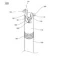
도 2: 본 발명의 바람직한 실시예에 따른 3차원 영상데이터를 제공하는 전자 내시경의 외관 사시도.
도 3: 본 발명의 바람직한 실시예에 따른 3차원 영상데이터를 제공하는 전자 내시경의 제 1 촬영부(140) 및 제 2 촬영부(150)가 돌출되어 펼쳐진 상태의 외관 단면도.
도 4: 본 발명의 바람직한 실시예에 따른 3차원 영상데이터를 제공하는 전자 내시경의 조명부(160) 까지 돌출된 상태의 외관 단면도.
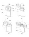
도 5: 본 발명의 바람직한 실시예에 따른 3차원 영상데이터를 제공하는 전자 내시경의 작동 순서도.
도 6: 본 발명의 바람직한 실시예에 따른 3차원 영상데이터를 제공하는 전자 내시경의 사용시 상태를 나타내는 모식도.
도 7: 본 발명의 다른 실시예에 따른 3차원 영상데이터를 제공하는 전자 내시경의 작동 순서도.
도 8: 본 발명의 다른 실시예에 따른 3차원 영상데이터를 제공하는 전자 내시경의 사용시 외관 사시도.
도 9: 본 발명의 다른 실시예에 따른 3차원 영상데이터를 제공하는 전자 내시경의 사용시 상태를 나타내는 모식도.1 is a perspective view of an endoscope providing conventional three-dimensional image data.
2 is an external perspective view of an electronic endoscope for providing three-dimensional image data according to a preferred embodiment of the present invention.
3 is an external cross-sectional view of a state in which the
4 is an external cross-sectional view of a state protruding to the
5 is an operational flowchart of an electronic endoscope for providing three-dimensional image data according to a preferred embodiment of the present invention.
6 is a schematic diagram showing a state in use of an electronic endoscope for providing three-dimensional image data according to a preferred embodiment of the present invention.
7 is an operational flowchart of an electronic endoscope for providing three-dimensional image data according to another embodiment of the present invention.
8 is a perspective view of the appearance of the electronic endoscope for providing three-dimensional image data according to another embodiment of the present invention.
9 is a schematic diagram showing a state of use of the electronic endoscope for providing three-dimensional image data according to another embodiment of the present invention.
이하에서는 첨부된 도면을 참조로 하여, 본 발명의 일 실시 예에 따른 3차원 영상데이터를 제공하는 전자 내시경을 상세히 설명한다. 우선, 도면들 중, 동일한 구성요소 또는 부품들은 가능한 한 동일한 참조부호로 나타내고 있음에 유의하여야 한다. 본 발명을 설명함에 있어, 관련된 공지 기능 혹은 구성에 관한 구체적인 설명은 본 발명의 요지를 모호하지 않게 하기 위하여 생략한다.
Hereinafter, an electronic endoscope for providing 3D image data according to an embodiment of the present invention will be described in detail with reference to the accompanying drawings. First, it should be noted that, in the drawings, the same components or parts are denoted by the same reference numerals whenever possible. In describing the present invention, detailed descriptions of related well-known functions or configurations are omitted in order not to obscure the subject matter of the present invention.
본 발명은 도 2 및 도 3에 도시한 것과 같이 크게 선단부(110), 절곡부(120), 몸체(130), 제 1 촬영부(140) 및 제 2 촬영부(150)를 포함하여 구성된다.
2 and 3, the present invention includes a
먼저, 선단부(110)에 관하여 설명한다. 상기 선단부(110)는 도 2에 도시한 것과 같이 전단이 개방되어 있으며, 내부에는 후술할 제 1 촬영부(140) 및 제 2 촬영부(150)가 수납될 수 있는 공간이 형성되어 있다.
First, the
다음으로, 절곡부(120)에 관하여 설명한다. 상기 절곡부(120)는 도 2에 도시한 것과 같이 상기 선단부(110)의 후단에 연결되어 상기 선단부(110)가 환자의 체내에 삽입되면 상기 몸체(130)에 대하여 원하는 각도로 구부러지는 것이 가능하도록 하는 기능을 가진다. 상기 절곡부(120)를 구성하는 기계적인 구성은 대단히 다양한 구성이 가능하며, 본 발명이 속하는 분야에서는 공지의 기술에 속하므로 상세한 설명은 생략한다.
Next, the
다음으로, 제 1 촬영부(140) 및 제 2 촬영부(150)에 관하여 설명한다. 상기 제 1 촬영부(140)는 도 2에 도시한 것과 같이 수납 상태에서는 상기 선단부(110)의 내부 일측면에 수납될 수 있도록 설치된다. 상기 제 1 촬영부(140)의 하단에는 도 3에 도시한 것과 같이, 제 1 작동 로드(142)가 연결되어 상기 제 1 작동 로드(142)의 작동에 연동하여 상하 방향 및 회전 방향의 작동이 가능하다. 또한, 상기 제 1 촬영부(140)의 전면에는 도 3에 도시한 것과 같이 촬영소자(141)가 설치된다. 상기 촬영소자(141)는 렌즈와 CCD(Charge Coupled Device)를 포함하여 구성하는 것이 가능하며, 이 경우 상기 렌즈는 줌기능과 틸트기능을 가지는 것이 바람직하다. 상기 CCD(Charge Coupled Device)와 렌즈를 이용하여 상기 촬영소자(141)를 구성하는 기술 및 줌(zoom)/틸트(tilt)기능에 관한 기술은 본 발명이 속하는 기술분야에 있어서 공지기술이므로, 상세한 설명을 생략하기로 한다.
Next, the first photographing
한편, 상기 제 2 촬영부(150)는 도 2에 도시한 것과 같이 수납 상태에서는 상기 선단부(110)의 내부 타측면에 상기 제 1 촬영부(140)의 아래에 위치하며 수납될 수 있도록 설치된다. 상기 제 2 촬영부(150)의 하단에는 도 3에 도시한 것과 같이, 제 2 작동 로드(151)가 연결되어 상기 제 2 작동 로드(151)의 작동에 연동하여 상하 방향 및 회전 방향의 작동이 가능하다. 또한, 상기 제 2 촬영부(150)의 전면에는 도 3에 도시한 것과 같이 촬영소자(141)가 설치된다.
Meanwhile, as shown in FIG. 2, the second photographing
다음으로, 조명부(160)에 관하여 설명한다. 상기 조명부(160)는 도 5a에 도시한 것과 같이, 수납상태에서 상기 선단부(110)의 내부 중앙축에 상기 제 2 촬영부(150)의 아래에 위치하며 수납될 수 있도록 설치된다. 상기 조명부(160)의 하단에는 제 3 작동 로드(161)가 연결되어, 상기 제 3 작동 로드(161의 작동에 연동하여 상기 조명부(160)의 상하 방향의 작동이 가능하다. 상기 조명부(160)의 전면에는 도 4에 도시한 것과 같이 하나 이상의 조명 수단(162)이 전면에 설치되어 환자의 체내에서 사용되는 경우 환부에 조명을 공급할 수 있도록 하는 것이 바람직하다. 상기 조명 수단(162)을 구성하는 실시예로는 엘이디(LED: Light Emitting Diode)를 사용하거나, 외부에 설치된 광원에 상기 몸체(130)를 통하여 연결된 광섬유를 사용하는 구성 등 대단히 다양한 구성이 가능하다. 이러한 상기 조명 수단(162)을 구성하는 기술은 본 발명이 속하는 분야에서는 공지의 기술이므로, 상세한 설명은 생략한다.
Next, the
한편, 상기 제 1 작동 로드(142), 상기 제 2 작동 로드(151) 및 상기 제 3 작동 로드(161)는 상기 절곡부(120)의 굽힘작동을 고려하여, 탄성을 가지는 재질로 구성되는 것이 바람직하다. 상기 제 1 작동 로드(142), 상기 제 2 작동 로드(151) 및 상기 제 3 작동 로드(161)는 상기 몸체(130)의 내부를 통하여 외부로 연결되어, 시술자의 조작에 따라 작동하게 된다.
Meanwhile, the
한편, 본 발명의 다른 실시예에 의한 3차원 영상데이터를 제공하는 전자 내시경은 도 7 및도 8에 도시한 것과 같이 상기 제 1 촬영부(140), 상기 제 2 촬영부(150) 및 상기 조명부(160)의 형상 또는 설치위치를 달리하여 실시하는 것도 가능하다. 이 경우, 상기 조명부(160)는 도 7 또는 도 8에 도시한 것과 같이 상기 선단부(110)의 전단에 형성되어 설치되는 것이 바람직하다. 또한, 상기 제 1 촬영부(140)는 도 7 및 도 8에 도시한 것과 같이 상기 선단부(110)의 일측면에 형성된 제 1 슬릿(111)을 통과하며 설치된 제 1 작동 로드(142)가 일 측면에 연결되고, 상기 제 1 작동 로드(142)의 작동에 연동하여 상하 방향 및 회전 방향의 작동이 가능하도록 설치되는 것이 바람직하다. 그리고, 상기 제 2 촬영부(150)는 도 7 및 도 8에 도시한 것과 같이, 상기 선단부(110)의 타측면에 형성된 제 2 슬릿(112)을 통과하며 설치된 제 2 작동 로드(151)가 일 측면에 연결되고, 상기 제 2 작동 로드(151)의 작동에 연동하여 상하 방향 및 회전 방향의 작동이 가능하도록 설치되는 것이 바람직하다. 이 경우, 수납 위치에서는 도 7a에 도시한 것과 같이 상기 제 2 촬영부(150)는 상기 선단부(110)와 상기 제 1 촬영부(140) 사이에 위치하게 된다.
On the other hand, the electronic endoscope providing the 3D image data according to another embodiment of the present invention, as shown in Figure 7 and 8, the
이러한 본 발명의 다른 실시예에 의한 3차원 영상데이터를 제공하는 전자 내시경을 구현하는 경우, 상기 선단부(110), 상기 제 1 촬영부(140), 상기 제 2 촬영부(150), 상기 제 1 작동 로드(142) 및 상기 제 2 작동 로드(151)의 형상이 모두 원통형인 것이 가능하다. 이 경우, 각각 상기 선단부(110)의 직경을 R0, 상기 제 1 촬영부(140)의 직경을 R1, 상기 제 2 촬영부(150)의 직경을 R2, 상기 제 1 작동 로드(142) 및 상기 제 2 작동 로드(151)의 직경을 R3라 한다면, 상기, R0~R3사이에는 원활한 작동을 위하여 다음과 같은 관계가 성립되는 것이 바람직하다.
When implementing the electronic endoscope for providing three-dimensional image data according to another embodiment of the present invention, the


이하에서는, 본 발명의 일 실시예에 의한 3차원 영상데이터를 제공하는 전자 내시경(100)의 작동에 관하여 설명한다.
Hereinafter, the operation of the
먼저, 수납 상태에서는 도 5 a에 도시한 것과 같이, 상기 선단부(110)의 내부에 외부로부터 상기 제 1 촬영부(140), 상기 제 2 촬영부(150) 및 상기 조명부(160)의 순서대로 수납된다. 이렇게 수납된 상태에서 상기 선단부(110), 절곡부(120) 및 상기 몸체(130)가 절개부위를 통하여 환자의 체내로 삽입된다.
First, in a stored state, as shown in FIG. 5A, in order of the first photographing
그 후, 도 5 b에 도시한 것과 같이, 먼저 상기 제 1 촬영부(140)가 상기 제 1 작동로드(142)의 작동에 의해 상기 선단부(110)의 외부로 돌출된 후, 상기 제 1 작동로드(142)의 회전에 의해 상기 선단부(110)의 외주연의 연장선 외부로 전개된다.Thereafter, as shown in FIG. 5B, first the first photographing
다음으로, 도 5 c에 도시한 것과 같이, 상기 제 2 촬영부(150)가 상기 제 2 작동로드(151)의 작동에 의해 상기 선단부(110)의 외부로 돌출된 후, 상기 제 2 작동로드(151)의 회전에 의해 상기 선단부(110)의 외주연의 연장선 외부로 전개된다. 이러한 상기 제 1 촬영부(140)와 상기 제 2 촬영부(150)의 팝업(pop-up)식 돌출/전개 작동에 의하여, 상기 제 1 촬영부(140)와 상기 제 2 촬영부(150)가 작동 상태에서 도 6에 도시한 것과 같이 상기 몸체(130)의 직경보다 넓은 폭으로 돌출하여 전개되는 것이 가능하기에, 절개 부위의 폭을 최소화 하면서도 효과적으로 입체적인 영상을 얻는 것이 가능하게 된다.
Next, as shown in FIG. 5C, after the second photographing
한편, 상기 조명부(160)를 포함하여 구성되는 경우에는 도 5 d에 도시한 것과 같이, 상기 제 3 작동로드(161)의 작동에 의해 상기 조명부(160)가 상기 선단부(110)의 외부로 돌출되어 상기 제 1 촬영부(140)와 상기 제 2 촬영부(150)의 사이에 위치하며, 도 6에 도시한 것과 같이 환부를 조명하게 된다.
Meanwhile, when the
본 발명의 일 실시예에 의한 3차원 영상데이터를 제공하는 전자 내시경(100)의 사용이 완료된 이후에는, 상기한 돌출/전개 과정의 역순으로 상기 조명부(160), 상기 제 2 촬영부(150) 및 상기 제 1 촬영부(110)가 순차적으로 상기 선단부(110)의 내부에 다시 수납된다. 따라서, 상기 선단부(110)를 포함하는 상기 몸체(130)의 외경을 초과하는 범위에는 어떠한 돌출 구조물도 존재하지 않게 되어 절개 폭을 최소화한 절개 부위로 쉽게 상기 선단부(110)와 몸체(130)를 빼내는 것이 가능하다.
After the use of the
한편, 본 발명의 다른 실시예에 의한 3차원 영상데이터를 제공하는 전자 내시경의 경우의 작동은 도 7에 도시한 것과 같은 순서로 진행된다.
On the other hand, the operation of the electronic endoscope for providing the three-dimensional image data according to another embodiment of the present invention proceeds in the same order as shown in FIG.
먼저, 도 7a에 도시한 것과 같이 상기 제 1 촬영부(140), 상기 제 2 촬영부(150) 및 상기 선단부(110)가 서로 겹쳐진 상태로 환자의 체내에 삽입된다.
First, as shown in FIG. 7A, the
그 후, 도 7b에 도시한 것과 같이, 먼저 상기 제 1 촬영부(140)가 상기 제 1 작동 로드(142)의 작동에 연동하여 상기 선단부(110)의 외주연 외측으로 회전하며 전개된후, 도 7c에 도시한 것과 같이 상기 제 1 작동 로드(142)가 하강하며 작동하는 것에 연동하여 상기 선단부(110)의 상면과 같은 높이까지 하강한다. 이 경우, 상기 제 1 촬영부(140)와 상기 제 1 작동 로드(142)가 연결된 부위가 상기 제 1 슬릿(111)에 삽입되듯이 위치하게 된다.
Thereafter, as shown in FIG. 7B, first, the first photographing
다음으로, 도 7d에 도시한 것과 같이, 상기 제 2 촬영부(150)가 상기 제 2 작동 로드(151)의 작동에 연동하여 상기 선단부(110)의 외주연 외측으로 회전하며 전개된후, 도 8에 도시한 것과 같은 위치로 이 상기 제 2 작동 로드(151)가 하강하며 작동하는 것에 연동하여 상기 선단부(110)의 상면과 같은 높이까지 하강한다. 이 경우, 상기 제 2 촬영부(150)와 상기 제 2 작동 로드(151)가 연결된 부위 역시 상기 제 2 슬릿(112)에 삽입되듯이 위치하게 된다.
Next, as shown in FIG. 7D, after the second photographing
본 발명의 다른 실시예에 의한 3차원 영상데이터를 제공하는 전자 내시경의 사용이 완료된 이후에는, 상기한 돌출/전개 과정의 역순으로 상기 제 2 촬영부(150) 및 상기 제 1 촬영부(110)가 순차적으로 상기 선단부(110)의 외주연 안쪽의 범위로 다시 수납된다. 따라서, 상기 선단부(110)를 포함하는 상기 몸체(130)의 외경을 초과하는 범위에는 어떠한 돌출 구조물도 존재하지 않게 되어 절개 폭을 최소화한 절개 부위로 쉽게 상기 선단부(110)와 몸체(130)를 빼내는 것이 가능하다.
After the use of the electronic endoscope for providing the 3D image data according to another embodiment of the present invention is completed, the second photographing
이상에서, 도면과 명세서에서 최적 실시 예들이 개시되었다. 여기서 특정한 용어들이 사용되었으나, 이는 단지 본 발명을 설명하기 위한 목적에서 사용된 것이지 의미한정이나 특허청구범위에 기재된 본 발명의 범위를 제한하기 위하여 사용된 것은 아니다. 그러므로 본 기술 분야의 통상의 지식을 가진 자라면 이로부터 다양한 변형 및 균등한 타 실시 예가 가능하다는 점을 이해할 것이다. 따라서 본 발명의 진정한 기술적 보호범위는 첨부된 특허청구범위의 기술적 사상에 의해 정해져야 할 것이다.
In the above, the best embodiments have been disclosed in the drawings and specification. Although specific terms have been used herein, they are used only for the purpose of describing the present invention and are not intended to limit the scope of the invention as defined in the claims or the claims. Therefore, those skilled in the art will appreciate that various modifications and equivalent embodiments are possible without departing from the scope of the present invention. Therefore, the true technical protection scope of the present invention will be defined by the technical spirit of the appended claims.
100: 내시경
110: 선단부
111: 제 1 슬릿112: 제 2 슬릿
120: 절곡부
130: 몸체
140: 제 1 촬영부141: 촬상소자
142: 제 1 작동 로드(rod)
150: 제 2 촬영부151: 제2 작동 로드(rod)
160: 조명부161: 조명수단
162: 제 3 작동 로드(rod)100: endoscope
110: tip end
111: first slit 112: second slit
120: bend
130: body
140: first photographing unit 141: imaging device
142: first working rod
150: second photographing unit 151: second operating rod
160: lighting unit 161: lighting means
162: third working rod
Claims (4)
Translated fromKorean상기 관형상의 몸체(130)는,
전단이 개방되어 있는 선단부(110);
상기 선단부(110)에 연결되며, 선단부(110)가 상기 몸체(130)에 대하여 일정 각도로 구부러지도록 형성되는 절곡부(120);
상기 선단부(110)의 내부 일측면에 설치되고, 하단에 연결된 제 1 작동 로드(142)의 작동에 연동하여 상하 방향 및 회전 방향의 작동이 가능하며, 촬영소자(141)가 전면에 설치되어 있는 제 1 촬영부(140);
상기 선단부(110)의 내부 타측면에 설치되고, 하단에 연결된 제 2 작동 로드(151)의 작동에 연동하여 상하 방향 및 회전 방향의 작동이 가능하며, 촬영소자(141)가 전면에 설치되어 있는 제 2 촬영부(150); 를 포함하여 구성되는 것을 특징으로 하는 3차원 영상데이터를 제공하는 전자 내시경(100).
In an endoscope having a pipe-shaped body 130 is inserted into the body of the patient to provide image information,
The tubular body 130,
A front end 110 having a front end open;
A bent part 120 connected to the front end part 110, the front end part 110 being bent at a predetermined angle with respect to the body 130;
It is installed on one inner surface of the front end portion 110, in conjunction with the operation of the first operation rod 142 connected to the lower end is possible to operate in the vertical direction and the rotation direction, the photographing element 141 is installed in the front First photographing unit 140;
It is installed on the other side of the inside of the tip portion 110, in conjunction with the operation of the second operation rod 151 connected to the bottom is possible to operate in the vertical direction and rotation direction, the photographing element 141 is installed on the front The second photographing unit 150; Electronic endoscope providing three-dimensional image data, characterized in that it comprises a.
상기 선단부(110)의 내부 중앙축에 설치되고, 하단에 연결된 제 3 작동 로드(161)의 작동에 연동하여 상하 방향의 작동이 가능하며, 하나 이상의 조명 수단(162)이 전면에 설치되어 있는 조명부(160); 를 더 포함하여 구성되는 것을 특징으로 하는 3차원 영상데이터를 제공하는 전자 내시경(100).
The method according to claim 1,
Is installed on the inner central shaft of the front end portion 110, in conjunction with the operation of the third operation rod 161 connected to the bottom can be operated in the vertical direction, the lighting unit having one or more lighting means 162 is installed on the front 160; Electronic endoscope (100) for providing three-dimensional image data, characterized in that further comprises.
상기 제 1 작동 로드(142), 상기 제 2 작동 로드(151) 및 상기 제 3 작동 로드(161)는 탄성을 가지는 재질로 구성되는 것을 특징으로 하는 3차원 영상데이터를 제공하는 전자 내시경(100).
The method according to claim 2,
The first endoscope rod 142, the second end rod 151 and the third end rod 161 is an electronic endoscope 100 for providing three-dimensional image data, characterized in that composed of a material having an elasticity .
상기 관형상의 몸체(130)는,
전단에 조명부(160)가 형성되어 있는 선단부(110);
상기 선단부(110)에 연결되며, 선단부(110)가 상기 몸체(130)에 대하여 일정 각도로 구부러지도록 형성되는 절곡부(120);
상기 선단부(110)의 일측면에 형성된 제 1 슬릿(111)을 통과하며 설치된 제 1 작동 로드(142)가 일 측면에 연결되고, 상기 제 1 작동 로드(142)의 작동에 연동하여 상하 방향 및 회전 방향의 작동이 가능하며, 촬영소자(141)가 전면에 설치되어 있는 제 1 촬영부(140);
상기 선단부(110)의 타측면에 형성된 제 2 슬릿(112)을 통과하며 설치된 제 2 작동 로드(151)가 일 측면에 연결되고, 상기 제 2 작동 로드(151)의 작동에 연동하여 상하 방향 및 회전 방향의 작동이 가능하며, 촬영소자(141)가 전면에 설치되어 있고, 수납시에는 상기 선단부(110)와 상기 제 1 촬영부(140) 사이에 위치하는 제 2 촬영부(150); 를 포함하여 구성되는 것을 특징으로 하는 3차원 영상데이터를 제공하는 전자 내시경(100).In an endoscope having a pipe-shaped body 130 is inserted into the body of the patient to provide image information,
The tubular body 130,
Front end portion 110 is formed in the front lighting unit 160;
A bent part 120 connected to the front end part 110, the front end part 110 being bent at a predetermined angle with respect to the body 130;
The first operating rod 142 installed while passing through the first slit 111 formed on one side of the tip portion 110 is connected to one side, and interlocked with the operation of the first operating rod 142 to move up and down. A first photographing unit 140 capable of operating in a rotational direction and having a photographing element 141 installed on a front surface thereof;
The second operating rod 151 installed while passing through the second slit 112 formed on the other side of the front end portion 110 is connected to one side, and interlocked with the operation of the second operating rod 151 in the up and down direction and A second photographing unit 150 capable of operating in a rotational direction and having a photographing element 141 disposed on a front surface thereof, which is located between the tip part 110 and the first photographing part 140 when stored; Electronic endoscope providing three-dimensional image data, characterized in that it comprises a.
Priority Applications (3)
| Application Number | Priority Date | Filing Date | Title |
|---|---|---|---|
| KR1020100023253AKR101070695B1 (en) | 2010-03-16 | 2010-03-16 | Electronic Endoscope for providing 3D image data |
| PCT/KR2011/001504WO2011115379A2 (en) | 2010-03-16 | 2011-03-04 | Popup type endoscope providing three-dimensional image data |
| US13/635,676US20130006052A1 (en) | 2010-03-16 | 2011-03-04 | Popup type endoscope providing three-dimensional image data |
Applications Claiming Priority (1)
| Application Number | Priority Date | Filing Date | Title |
|---|---|---|---|
| KR1020100023253AKR101070695B1 (en) | 2010-03-16 | 2010-03-16 | Electronic Endoscope for providing 3D image data |
Publications (2)
| Publication Number | Publication Date |
|---|---|
| KR20110104234A KR20110104234A (en) | 2011-09-22 |
| KR101070695B1true KR101070695B1 (en) | 2011-10-07 |
Family
ID=44649691
Family Applications (1)
| Application Number | Title | Priority Date | Filing Date |
|---|---|---|---|
| KR1020100023253AExpired - Fee RelatedKR101070695B1 (en) | 2010-03-16 | 2010-03-16 | Electronic Endoscope for providing 3D image data |
Country Status (3)
| Country | Link |
|---|---|
| US (1) | US20130006052A1 (en) |
| KR (1) | KR101070695B1 (en) |
| WO (1) | WO2011115379A2 (en) |
Cited By (2)
| Publication number | Priority date | Publication date | Assignee | Title |
|---|---|---|---|---|
| KR101150350B1 (en) | 2011-12-26 | 2012-06-08 | 윤치순 | 3-dimensional endoscopic surgery apparratus |
| WO2015111921A1 (en)* | 2014-01-21 | 2015-07-30 | 가톨릭관동대학교 산학협력단 | Trans-platform apparatus and use thereof |
Families Citing this family (6)
| Publication number | Priority date | Publication date | Assignee | Title |
|---|---|---|---|---|
| FR2996437B1 (en)* | 2012-10-05 | 2014-12-19 | Centre Nat Rech Scient | MULTI-VISION IMAGING SYSTEM FOR LAPAROSCOPIC SURGERY |
| KR101941907B1 (en) | 2013-01-03 | 2019-01-24 | 삼성전자주식회사 | Endoscope using depth information and method for detecting polyp based on endoscope using depth information |
| KR102195714B1 (en)* | 2013-05-02 | 2020-12-28 | 삼성전자주식회사 | Trocar for surgery and method for obtaining image using the same |
| US10463443B2 (en) | 2016-02-17 | 2019-11-05 | Invuity, Inc. | Systems and methods for illuminating and imaging |
| WO2018199520A1 (en)* | 2017-04-27 | 2018-11-01 | 서울대학교병원 | Panoramic view telescope |
| JP2019076575A (en)* | 2017-10-26 | 2019-05-23 | 桂太郎 松本 | Endoscope system |
Citations (3)
| Publication number | Priority date | Publication date | Assignee | Title |
|---|---|---|---|---|
| US5305121A (en)* | 1992-06-08 | 1994-04-19 | Origin Medsystems, Inc. | Stereoscopic endoscope system |
| US20070032700A1 (en)* | 2003-07-15 | 2007-02-08 | Fowler Dennis L | Insertable device and system for minimal access procedure |
| KR100947624B1 (en)* | 2009-10-13 | 2010-03-15 | 주식회사 엠지비엔도스코피 | Endoscope for providing 3d image data |
Family Cites Families (8)
| Publication number | Priority date | Publication date | Assignee | Title |
|---|---|---|---|---|
| US6017358A (en)* | 1997-05-01 | 2000-01-25 | Inbae Yoon | Surgical instrument with multiple rotatably mounted offset end effectors |
| KR20050059168A (en)* | 2002-09-30 | 2005-06-17 | 사이트라인 테크놀로지스 리미티드 | Piston-actuated endoscopic tool |
| US7029435B2 (en)* | 2003-10-16 | 2006-04-18 | Granit Medical Innovation, Llc | Endoscope having multiple working segments |
| US8562516B2 (en)* | 2004-04-14 | 2013-10-22 | Usgi Medical Inc. | Methods and apparatus for obtaining endoluminal access |
| US8277373B2 (en)* | 2004-04-14 | 2012-10-02 | Usgi Medical, Inc. | Methods and apparaus for off-axis visualization |
| US8602971B2 (en)* | 2004-09-24 | 2013-12-10 | Vivid Medical. Inc. | Opto-Electronic illumination and vision module for endoscopy |
| US8480566B2 (en)* | 2004-09-24 | 2013-07-09 | Vivid Medical, Inc. | Solid state illumination for endoscopy |
| US7621869B2 (en)* | 2005-05-06 | 2009-11-24 | Nitesh Ratnakar | Next generation colonoscope |
- 2010
- 2010-03-16KRKR1020100023253Apatent/KR101070695B1/ennot_activeExpired - Fee Related
- 2011
- 2011-03-04WOPCT/KR2011/001504patent/WO2011115379A2/enactiveApplication Filing
- 2011-03-04USUS13/635,676patent/US20130006052A1/ennot_activeAbandoned
Patent Citations (3)
| Publication number | Priority date | Publication date | Assignee | Title |
|---|---|---|---|---|
| US5305121A (en)* | 1992-06-08 | 1994-04-19 | Origin Medsystems, Inc. | Stereoscopic endoscope system |
| US20070032700A1 (en)* | 2003-07-15 | 2007-02-08 | Fowler Dennis L | Insertable device and system for minimal access procedure |
| KR100947624B1 (en)* | 2009-10-13 | 2010-03-15 | 주식회사 엠지비엔도스코피 | Endoscope for providing 3d image data |
Cited By (5)
| Publication number | Priority date | Publication date | Assignee | Title |
|---|---|---|---|---|
| KR101150350B1 (en) | 2011-12-26 | 2012-06-08 | 윤치순 | 3-dimensional endoscopic surgery apparratus |
| WO2015111921A1 (en)* | 2014-01-21 | 2015-07-30 | 가톨릭관동대학교 산학협력단 | Trans-platform apparatus and use thereof |
| KR101548646B1 (en) | 2014-01-21 | 2015-09-01 | 가톨릭관동대학교산학협력단 | Trans-Platform Apparatus and Their Uses |
| CN109521801A (en)* | 2014-01-21 | 2019-03-26 | 天主教关东大学校产学协力团 | A kind of position control |
| US10602915B2 (en) | 2014-01-21 | 2020-03-31 | Catholic Kwandong University Industry Foundation | Trans-platform apparatus and use thereof |
Also Published As
| Publication number | Publication date |
|---|---|
| WO2011115379A3 (en) | 2012-02-23 |
| US20130006052A1 (en) | 2013-01-03 |
| KR20110104234A (en) | 2011-09-22 |
| WO2011115379A2 (en) | 2011-09-22 |
Similar Documents
| Publication | Publication Date | Title |
|---|---|---|
| KR101070695B1 (en) | Electronic Endoscope for providing 3D image data | |
| US12383302B2 (en) | Surgical visualization systems and related methods | |
| US11744447B2 (en) | Surgical visualization systems and related methods | |
| US10028650B2 (en) | Device for three dimensional endoscopic surgery | |
| US8602980B2 (en) | Folding endoscope and method of using the same | |
| JP6045672B2 (en) | Arthroscopic system | |
| JP6453470B2 (en) | Endoscope that can be deployed and jointed using a single-use port | |
| CN104367296B (en) | Hand-held size with integrated distal end display minimizes diagnostic device | |
| KR101541988B1 (en) | Laparoscope system | |
| JP4481565B2 (en) | Multi-view endoscope | |
| US20110043609A1 (en) | Apparatus and method for processing a 3d image | |
| CN103989451B (en) | Endoscope and endoscopic apparatus | |
| JP2006505348A (en) | Endoscopic imaging system with removable deflection device | |
| US20110122229A1 (en) | Imaging System for Three-Dimensional Observation of an Operative Site | |
| CN105188504A (en) | Panoramic organ imaging | |
| JP2012075658A (en) | Endoscope apparatus | |
| AU2012202237A1 (en) | Pivoting three-dimensional video endoscope | |
| KR101070690B1 (en) | Electronic Endoscope for providing 3D image data | |
| JP2012090974A (en) | Electronic endoscope, attachment for endoscope, endoscope apparatus, and image acquiring method | |
| JP3486804B2 (en) | Tip structure of insertion section for oblique endoscope | |
| KR100947624B1 (en) | Endoscope for providing 3d image data | |
| AU2019223983A1 (en) | Surgical visualization systems and related methods | |
| KR100949998B1 (en) | Electronic endoscope for providing 3d image data | |
| KR101211353B1 (en) | Endoscope for providing 3D image data | |
| JP2022529012A (en) | Luminous tissue marker powered by light |
Legal Events
| Date | Code | Title | Description |
|---|---|---|---|
| A201 | Request for examination | ||
| PA0109 | Patent application | St.27 status event code:A-0-1-A10-A12-nap-PA0109 | |
| PA0201 | Request for examination | St.27 status event code:A-1-2-D10-D11-exm-PA0201 | |
| D13-X000 | Search requested | St.27 status event code:A-1-2-D10-D13-srh-X000 | |
| D14-X000 | Search report completed | St.27 status event code:A-1-2-D10-D14-srh-X000 | |
| E902 | Notification of reason for refusal | ||
| PE0902 | Notice of grounds for rejection | St.27 status event code:A-1-2-D10-D21-exm-PE0902 | |
| P11-X000 | Amendment of application requested | St.27 status event code:A-2-2-P10-P11-nap-X000 | |
| P13-X000 | Application amended | St.27 status event code:A-2-2-P10-P13-nap-X000 | |
| E701 | Decision to grant or registration of patent right | ||
| PE0701 | Decision of registration | St.27 status event code:A-1-2-D10-D22-exm-PE0701 | |
| R18-X000 | Changes to party contact information recorded | St.27 status event code:A-3-3-R10-R18-oth-X000 | |
| PG1501 | Laying open of application | St.27 status event code:A-1-1-Q10-Q12-nap-PG1501 | |
| GRNT | Written decision to grant | ||
| PR0701 | Registration of establishment | St.27 status event code:A-2-4-F10-F11-exm-PR0701 | |
| PR1002 | Payment of registration fee | St.27 status event code:A-2-2-U10-U11-oth-PR1002 Fee payment year number:1 | |
| PG1601 | Publication of registration | St.27 status event code:A-4-4-Q10-Q13-nap-PG1601 | |
| FPAY | Annual fee payment | Payment date:20140930 Year of fee payment:4 | |
| PR1001 | Payment of annual fee | St.27 status event code:A-4-4-U10-U11-oth-PR1001 Fee payment year number:4 | |
| PN2301 | Change of applicant | St.27 status event code:A-5-5-R10-R13-asn-PN2301 St.27 status event code:A-5-5-R10-R11-asn-PN2301 | |
| FPAY | Annual fee payment | Payment date:20150924 Year of fee payment:5 | |
| PR1001 | Payment of annual fee | St.27 status event code:A-4-4-U10-U11-oth-PR1001 Fee payment year number:5 | |
| FPAY | Annual fee payment | Payment date:20170329 Year of fee payment:6 | |
| PR1001 | Payment of annual fee | St.27 status event code:A-4-4-U10-U11-oth-PR1001 Fee payment year number:6 | |
| PR1001 | Payment of annual fee | St.27 status event code:A-4-4-U10-U11-oth-PR1001 Fee payment year number:7 | |
| FPAY | Annual fee payment | Payment date:20181001 Year of fee payment:8 | |
| PR1001 | Payment of annual fee | St.27 status event code:A-4-4-U10-U11-oth-PR1001 Fee payment year number:8 | |
| PR1001 | Payment of annual fee | St.27 status event code:A-4-4-U10-U11-oth-PR1001 Fee payment year number:9 | |
| PR1001 | Payment of annual fee | St.27 status event code:A-4-4-U10-U11-oth-PR1001 Fee payment year number:10 | |
| PR1001 | Payment of annual fee | St.27 status event code:A-4-4-U10-U11-oth-PR1001 Fee payment year number:11 | |
| PC1903 | Unpaid annual fee | St.27 status event code:A-4-4-U10-U13-oth-PC1903 Not in force date:20220930 Payment event data comment text:Termination Category : DEFAULT_OF_REGISTRATION_FEE | |
| R18-X000 | Changes to party contact information recorded | St.27 status event code:A-5-5-R10-R18-oth-X000 | |
| PN2301 | Change of applicant | St.27 status event code:A-5-5-R10-R13-asn-PN2301 St.27 status event code:A-5-5-R10-R11-asn-PN2301 | |
| PC1903 | Unpaid annual fee | St.27 status event code:N-4-6-H10-H13-oth-PC1903 Ip right cessation event data comment text:Termination Category : DEFAULT_OF_REGISTRATION_FEE Not in force date:20220930 |