KR101070635B1 - Constant velocity joint assembly - Google Patents
Constant velocity joint assemblyDownload PDFInfo
- Publication number
- KR101070635B1 KR101070635B1KR1020110049026AKR20110049026AKR101070635B1KR 101070635 B1KR101070635 B1KR 101070635B1KR 1020110049026 AKR1020110049026 AKR 1020110049026AKR 20110049026 AKR20110049026 AKR 20110049026AKR 101070635 B1KR101070635 B1KR 101070635B1
- Authority
- KR
- South Korea
- Prior art keywords
- guide
- spider
- block
- shaft
- joint assembly
- Prior art date
- Legal status (The legal status is an assumption and is not a legal conclusion. Google has not performed a legal analysis and makes no representation as to the accuracy of the status listed.)
- Expired - Fee Related
Links
Images


Classifications
- F—MECHANICAL ENGINEERING; LIGHTING; HEATING; WEAPONS; BLASTING
- F16—ENGINEERING ELEMENTS AND UNITS; GENERAL MEASURES FOR PRODUCING AND MAINTAINING EFFECTIVE FUNCTIONING OF MACHINES OR INSTALLATIONS; THERMAL INSULATION IN GENERAL
- F16D—COUPLINGS FOR TRANSMITTING ROTATION; CLUTCHES; BRAKES
- F16D3/00—Yielding couplings, i.e. with means permitting movement between the connected parts during the drive
- F16D3/16—Universal joints in which flexibility is produced by means of pivots or sliding or rolling connecting parts
- F16D3/26—Hooke's joints or other joints with an equivalent intermediate member to which each coupling part is pivotally or slidably connected
- F16D3/30—Hooke's joints or other joints with an equivalent intermediate member to which each coupling part is pivotally or slidably connected in which the coupling is specially adapted to constant velocity-ratio
- F16D3/32—Hooke's joints or other joints with an equivalent intermediate member to which each coupling part is pivotally or slidably connected in which the coupling is specially adapted to constant velocity-ratio by the provision of two intermediate members each having two relatively perpendicular trunnions or bearings
- F16D3/33—Hooke's joints or other joints with an equivalent intermediate member to which each coupling part is pivotally or slidably connected in which the coupling is specially adapted to constant velocity-ratio by the provision of two intermediate members each having two relatively perpendicular trunnions or bearings with ball or roller bearings
- F—MECHANICAL ENGINEERING; LIGHTING; HEATING; WEAPONS; BLASTING
- F16—ENGINEERING ELEMENTS AND UNITS; GENERAL MEASURES FOR PRODUCING AND MAINTAINING EFFECTIVE FUNCTIONING OF MACHINES OR INSTALLATIONS; THERMAL INSULATION IN GENERAL
- F16D—COUPLINGS FOR TRANSMITTING ROTATION; CLUTCHES; BRAKES
- F16D3/00—Yielding couplings, i.e. with means permitting movement between the connected parts during the drive
- F16D3/16—Universal joints in which flexibility is produced by means of pivots or sliding or rolling connecting parts
- F16D3/26—Hooke's joints or other joints with an equivalent intermediate member to which each coupling part is pivotally or slidably connected
- F16D3/30—Hooke's joints or other joints with an equivalent intermediate member to which each coupling part is pivotally or slidably connected in which the coupling is specially adapted to constant velocity-ratio
- F16D3/32—Hooke's joints or other joints with an equivalent intermediate member to which each coupling part is pivotally or slidably connected in which the coupling is specially adapted to constant velocity-ratio by the provision of two intermediate members each having two relatively perpendicular trunnions or bearings
- F—MECHANICAL ENGINEERING; LIGHTING; HEATING; WEAPONS; BLASTING
- F16—ENGINEERING ELEMENTS AND UNITS; GENERAL MEASURES FOR PRODUCING AND MAINTAINING EFFECTIVE FUNCTIONING OF MACHINES OR INSTALLATIONS; THERMAL INSULATION IN GENERAL
- F16D—COUPLINGS FOR TRANSMITTING ROTATION; CLUTCHES; BRAKES
- F16D3/00—Yielding couplings, i.e. with means permitting movement between the connected parts during the drive
- F16D3/16—Universal joints in which flexibility is produced by means of pivots or sliding or rolling connecting parts
- F16D3/26—Hooke's joints or other joints with an equivalent intermediate member to which each coupling part is pivotally or slidably connected
- F16D3/30—Hooke's joints or other joints with an equivalent intermediate member to which each coupling part is pivotally or slidably connected in which the coupling is specially adapted to constant velocity-ratio
Landscapes
- Engineering & Computer Science (AREA)
- General Engineering & Computer Science (AREA)
- Mechanical Engineering (AREA)
- Pivots And Pivotal Connections (AREA)
- Braking Arrangements (AREA)
- Automatic Assembly (AREA)
- Shafts, Cranks, Connecting Bars, And Related Bearings (AREA)
Abstract
Translated fromKoreanDescription
Translated fromKorean본 발명은 자동차의 구동축에 적용되는 등속조인트 어셈블리에 관한 것이다.The present invention relates to a constant velocity joint assembly applied to a drive shaft of a motor vehicle.
종래의 더블 카르단 등속조인트 어셈블리(double cardan constant velocity assembly)로는 미국특허 US6,840,864가 소개된바 있다.As a conventional double cardan constant velocity assembly, US Pat. No. 6,840,864 has been introduced.
그런데 이러한 종래의 등속조인트 어셈블리는 요크블록(inner ring)과 결합되는 다리부(cross pin)가 샤프트(shaft)의 선단부에 직접적으로 연결됨에 따라, 샤프트의 선단부의 자유도가 낮아져 작동 성능의 향상에 한계가 있었다. 또한, 그 연결 구조상 제작성이 떨어지고 패키지(package)의 규모가 커지게 되는 문제가 있었다.However, the conventional constant velocity joint assembly has a limit in improving the operating performance because the degree of freedom at the tip of the shaft is lowered as a cross pin coupled to the yoke block is directly connected to the tip of the shaft. There was. In addition, there is a problem that the manufacturability is deteriorated and the size of the package becomes large due to the connection structure.
또한, 종래의 등속조인트 어셈블리는 두 개의 샤프트의 선단부와 체결되는 중앙부(intermediate coupling member)의 구조상, 중앙부에 대한 샤프트의 작동이 원활하게 이루어지는데 한계가 있었다. 이에 따라 종래의 등속조인트 어셈블리의 중앙부는 보다 성능 향상이 이루어질 수 있는 구조로 변경될 필요가 있었다.In addition, the conventional constant velocity joint assembly has a limitation in that the shaft is smoothly operated due to the structure of an intermediate coupling member engaged with the front ends of the two shafts. Accordingly, the central portion of the conventional constant velocity joint assembly needs to be changed to a structure in which performance improvement can be achieved.
본 발명은 전술한 바와 같은 문제점들을 해결하기 위해 창출된 것으로서, 본 발명이 해결하고자 하는 과제는 제작성이 향상되어 가격 경쟁력이 확보되고, 패키지가 작은 규모로 구비되며, 종래에 비해 작동 성능이 크게 향상될 수 있는 등속조인트 어셈블리를 제공하는 것이다.The present invention has been created to solve the problems described above, the problem to be solved by the present invention is to improve the manufacturability is secured price competitiveness, the package is provided on a small scale, the operation performance is significantly larger than the conventional It is to provide a constant velocity joint assembly that can be improved.
상기한 과제를 달성하기 위한 본 발명의 한 실시예에 따른 등속조인트 어셈블리는 돌기부를 각각 구비하는 제1 및 제2 샤프트부, 축 방향으로 가이드 홀이 형성되고 상기 가이드 홀의 양측에 상기 제1 및 제2 샤프트부가 상하방향을 축으로 회전가능하게 각각 체결되는 더블요크부, 그리고 상기 가이드 홀에 장착되어, 상기 돌기부를 가이드 하고 상기 제1 및 제2 샤프트부의 회전 시 상기 가이드 홀의 내주면을 따라 회전되는 가이드부를 포함하며, 상기 제1 및 제2 샤프트부는 각각 스파이더 홀이 형성되는 스파이더몸체, 상기 스파이더몸체로부터 좌우방향으로 각각 돌출되는 좌우다리부, 및 상기 스파이더몸체로부터 상하방향으로 각각 돌출되어 상기 더블요크부에 체결되는 상하다리부를 포함하는 스파이더, 상기 돌기부를 구비하는 샤프트, 그리고 블록 홀이 형성되고 상기 블록 홀을 통해 상기 돌기부가 통과되며 상기 샤프트에 연결되는 블록몸체, 및 상기 블록몸체의 좌우측으로부터 축 방향으로 각각 돌출되고 상기 좌우다리부가 회전가능하게 체결되도록 체결구멍이 각각 형성되는 좌우체결부재를 포함하는 요크블록을 포함한다.The constant velocity joint assembly according to an embodiment of the present invention for achieving the above object is a first and second shaft portion having a projection, respectively, the guide hole is formed in the axial direction and the first and second on both sides of the
상기 더블요크부는 상기 가이드 홀이 형성되는 더블요크몸체, 그리고 상기 더블요크몸체의 상하측으로부터 상기 가이드 홀의 양측으로 각각 돌출되고 상기 상하다리부가 회전가능하게 체결되도록 체결구멍이 각각 형성되는 상하체결부재를 포함할 수 있다.The double yoke part includes a double yoke body in which the guide hole is formed, and an upper and lower fastening member each protruding from the upper and lower sides of the double yoke body to both sides of the guide hole, and fastening holes formed so that the upper and lower parts are rotatably fastened. It may include.
상기 좌우다리부는 상기 스파이더몸체로부터 상기 상하다리부보다 짧게 돌출될 수 있다.The left and right legs may protrude shorter than the upper and lower legs from the spider body.
상기 샤프트와 상기 요크블록은 각각 별도로 제작되어 조립될 수 있다.The shaft and the yoke block may be separately manufactured and assembled.
상기 스파이더는 상기 좌우다리부와 상기 좌우체결부재의 체결구멍 사이, 그리고 상기 상하다리부와 상기 상하체결부재의 체결구멍 사이에 각각 장착되는 니들베어링을 더 포함할 수 있다.The spider may further include needle bearings mounted between the left and right leg portions and the fastening holes of the left and right fastening members, and between the upper and lower legs and the fastening holes of the upper and lower fastening members, respectively.
상기 가이드부는 상기 각각의 돌기부를 수용하여 가이드 하도록 축 방향으로 가이드통로가 형성되는 가이드블록을 포함할 수 있다.The guide unit may include a guide block in which a guide passage is formed in the axial direction to receive and guide the respective protrusions.
상기 가이드통로는 상기 제1 및 제2 샤프트부가 상기 더블요크부와 이루는 각도에 따라 상기 각각의 돌기부가 수용될 수 있는 위치에 형성될 수 있다.The guide passage may be formed at a position where the respective protrusions may be accommodated according to an angle formed by the first and second shaft parts with the double yoke part.
상기 가이드부는 상기 가이드 홀과 상기 가이드블록 사이에 개재되는 윤활성 부싱부를 포함할 수 있다.The guide part may include a lubricity bushing part interposed between the guide hole and the guide block.
상기 가이드부는 상기 가이드 홀과 상기 가이드블록 사이에 개재되는 러버 부싱부를 포함할 수 있다.The guide part may include a rubber bushing part interposed between the guide hole and the guide block.
상기 러버 부싱부는 상기 가이드블록의 외주면을 감싸는 내측 튜브, 상기 내측 튜브의 외주면을 감싸는 러버 부싱, 그리고 상기 러버 부싱의 외주면을 감싸는 외측 튜브를 포함할 수 있다.The rubber bushing part may include an inner tube surrounding the outer circumferential surface of the guide block, a rubber bushing surrounding the outer circumferential surface of the inner tube, and an outer tube surrounding the outer circumferential surface of the rubber bushing.
상기 가이드부는 상기 가이드 홀과 상기 러버 부싱부 사이에 개재되는 윤활성 부싱부를 포함할 수 있다.The guide part may include a lubricity bushing part interposed between the guide hole and the rubber bushing part.
상기 윤활성 부싱부는 상기 러버 부싱부를 감싸는 스러스트 베어링, 상기 스러스트 베어링의 외주면을 감싸고 상기 가이드 홀의 내주면에 맞닿게 구비되며 상기 러버 부싱부의 일면의 둘레를 감싸도록 일단으로부터 둘레를 따라 반경방향 내측으로 연장되는 돌기부재를 포함하는 윤활성 플레이트, 그리고 상기 러버 부싱부의 타면의 둘레를 감싸는 와셔를 포함할 수 있다.The lubricity bushing portion is provided with a thrust bearing surrounding the rubber bushing portion, an outer circumferential surface of the thrust bearing and abutting the inner circumferential surface of the guide hole, and a protrusion extending radially inward along a circumference from one end to surround a circumference of one surface of the rubber bushing portion. Lubricating plate including a member, and a washer surrounding the other surface of the rubber bushing portion.
상기 가이드통로의 내측에는 가이드부싱이 배치될 수 있다.A guide bushing may be disposed inside the guide passage.
상기 가이드통로의 내측에는 상기 각각의 돌기부 사이에 탄성부재가 배치될 수 있다.An elastic member may be disposed inside the guide passage between the protrusions.
상기 가이드통로의 내측에는 상기 각각의 돌기부 사이에 상기 각각의 돌기부의 회전을 가이드 하는 형상의 가이드베어링이 배치될 수 있다.A guide bearing having a shape for guiding the rotation of each of the protrusions may be disposed between the protrusions inside the guide passage.
상기 스파이더 홀의 내측에는 스파이더 러버 부싱이 배치될 수 있다.A spider rubber bushing may be disposed inside the spider hole.
상기 가이드 홀에는 상기 가이드부의 양측에 각각 홈이 형성되고, 상기 더블요크부는 상기 가이드부의 위치가 고정되도록 상기 각각의 홈에 삽입되어 장착되는 스토퍼부재를 포함할 수 있다.The guide hole may have grooves formed at both sides of the guide part, and the double yoke part may include a stopper member inserted into and mounted in the respective grooves to fix the position of the guide part.
상기 홈은 상기 가이드 홀의 내주면에 원주방향을 따라 형성되고, 상기 스토퍼부재는 일부 절개되어 슬롯이 형성된 링 형상으로 구비될 수 있다.The groove may be formed along the circumferential direction on the inner circumferential surface of the guide hole, and the stopper member may be partially cut to have a ring shape having a slot.
본 발명에 의하면, 샤프트의 돌기부가 스파이더와는 직접적으로 연결되지 않은 상태로 스파이더 홀을 통과하여 더블요크부의 내측에 장착되는 가이드부에 수용되도록 구비되고, 이러한 샤프트와는 별도로 제작되어 요크블록과 더블요크부에 각 회전축(좌우 및 상하다리부)이 회전 가능하게 조립 연결되도록 스파이더가 구비됨으로써, 본 등속조인트 어셈블리의 작동 성능이 향상될 수 있으며, 아울러 조립성 및 제작성이 향상되어 가격 경쟁력이 확보될 수 있다.According to the present invention, the protrusion of the shaft is provided to be accommodated in the guide portion which is mounted inside the double yoke portion through the spider hole in a state in which it is not directly connected to the spider, and is manufactured separately from the shaft and doubled with the yoke block. The spider is provided so that each rotation shaft (left and right and upper and lower legs) can be rotatably assembled to the yoke part, thereby improving the operation performance of the constant velocity joint assembly, and also improving the assemblability and fabrication to secure a price competitiveness. Can be.
또한, 스파이더의 형상을 비대칭으로 구비함으로써, 요크블록과 더블요크부 사이의 간섭을 피하면서, 패키지(package)의 규모를 축소할 수 있으며, 샤프트와 요크블록을 각각 별도로 제작한 후 조립할 수 있어, 제작성이 보다 향상될 수 있다.In addition, by providing an asymmetrical shape of the spider, the size of the package can be reduced while avoiding interference between the yoke block and the double yoke portion, and the shaft and the yoke block can be manufactured separately and then assembled. The manufacturability can be further improved.
또한, 더블요크부의 내측에 장착되는 가이드부에 윤활성 부싱부와 러버 부싱부를 구비함으로써, 종래에 비해 원활한 회전이 이루어지며 샤프트의 돌기부가 가이드 될 수 있고, 작동 시의 진동이 흡수될 수 있으며, 이에 따라 본 등속조인트 어셈블리의 작동 안정성 및 성능이 크게 향상될 수 있다.In addition, by providing a lubricating bushing portion and a rubber bushing portion in the guide portion mounted inside the double yoke portion, smooth rotation is achieved and the protrusion of the shaft can be guided, and vibration during operation can be absorbed. Accordingly, the operational stability and performance of the constant velocity joint assembly can be greatly improved.
또한, 윤활성 플레이트의 돌기부재와 와셔가 후술할 스토퍼부재와 조합됨으로써, 가이드부의 이탈을 방지할 수 있고, 축 방향 유격을 제거하여 축 방향에 대한 흔들림을 방지할 수 있다.In addition, by combining the protrusion member and the washer of the lubricity plate with the stopper member to be described later, it is possible to prevent the separation of the guide portion, it is possible to remove the axial play to prevent the shaking in the axial direction.
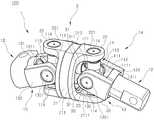
도 1은 본 발명의 한 실시예에 따른 등속조인트 어셈블리의 사시도이다.
도 2는 본 발명의 한 실시예에 따른 등속조인트 어셈블리의 평면도 및 본 발명의 한 실시예에 따른 등속조인트 어셈블리를 위에서 비스듬하게 바라본 입체도이다.
도 3은 도 2의 III-III선을 따라 절개한 단면도이다.
도 4는 본 발명의 한 실시예에 따른 등속조인트 어셈블리의 정면도, 좌측면도, 및 우측면도이다.
도 5는 본 발명의 한 실시예에 따른 등속조인트 어셈블리의 분해사시도이다.1 is a perspective view of a constant velocity joint assembly according to an embodiment of the present invention.
Figure 2 is a plan view of a constant velocity joint assembly according to an embodiment of the present invention and a perspective view obliquely from above the constant velocity joint assembly according to an embodiment of the present invention.
3 is a cross-sectional view taken along the line III-III of FIG. 2.
4 is a front view, left side view, and right side view of a constant velocity joint assembly according to an embodiment of the present invention.
5 is an exploded perspective view of a constant velocity joint assembly according to an exemplary embodiment of the present invention.
이하에서 본 발명의 실시예를 첨부된 도면을 참조로 상세히 설명한다.Hereinafter, embodiments of the present invention will be described in detail with reference to the accompanying drawings.
도 1 내지 도 5를 참조하면, 본 발명의 한 실시예에 따른 등속조인트 어셈블리(이하 '본 등속조인트 어셈블리'라 함)(100)는 제1 및 제2 샤프트부(1, 1a)를 포함한다.1 to 5, the constant velocity joint assembly (hereinafter referred to as the 'main constant velocity joint assembly') 100 according to an embodiment of the present invention includes first and
제1 및 제2 샤프트부(1, 1a)는 돌기부(121)를 각각 구비한다.The first and
보다 구체적으로, 제1 및 제2 샤프트부(1, 1a)는 각각 스파이더(11), 샤프트(12), 그리고 요크블록(13)을 포함할 수 있다. 이하에서는 이와 같이 제1 및 제2 샤프트부(1, 1a)에 공통적으로 포함되는 구성들을 함께 설명한다.More specifically, the first and
도 1 내지 도 5를 참조하면, 스파이더(11)는 스파이더 홀(1111)이 형성되는 스파이더몸체(111), 스파이더몸체(111)로부터 좌우방향으로 각각 돌출되는 좌우다리부(112), 및 스파이더몸체(111)로부터 상하방향으로 각각 돌출되어 더블요크부(2)에 체결되는 상하다리부(113)를 포함할 수 있다.1 to 5, the
이러한 스파이더 홀(1111)을 통해 후술할 샤프트(12)의 돌기부(121)가 통과되어 가이드부(3)(가이드통로(311))에 수용될 수 있다. 또한, 좌우다리부(112)는 후술할 요크블록(13)의 체결구멍(1321)에 회전 가능하게 삽입되어 체결되고, 상하다리부(113)는 후술할 더블요크몸체(21)의 체결구멍(221)에 회전 가능하게 삽입되어 체결될 수 있다.Through the
이와 같이 샤프트(12)의 돌기부(121)가 스파이더(11)와는 직접적으로 연결되지 않은 상태로 스파이더 홀(1111)을 통과하도록 구비됨으로써, 샤프트(12)의 돌기부(121)의 끝단이 후술할 가이드부(3)에 수용된 상태로 보다 자유롭게 가이드 될 수 있어 본 등속조인트 어셈블리(100)의 작동 성능이 향상될 수 있으며, 아울러 조립성 및 제작성이 향상되어 가격 경쟁력이 확보될 수 있다.As such, the
또한, 이처럼 샤프트(12)와는 별도로 제작되고 요크블록(13)과 더블요크부(2)에 각 회전축(좌우 및 상하다리부(112, 113))이 회전 가능하게 조립 연결되도록 스파이더(11)가 구비되는 측면에 있어서도, 각 구성들 및 그 연결 관계가 보다 간명해질 수 있어, 본 등속조인트 어셈블리(100)의 조립성 및 제작성이 향상될 수 있고, 이에 따라 가격 경쟁력이 확보될 수 있다.In addition, the
여기서, 좌우방향 및 상하방향은 스파이더(11)의 축 방향(스파이더 홀(1111)이 관통되는 방향)을 기준으로 정의되는 방향일 수 있다. 즉, 스파이더(11)의 축 방향을 바라보았을 때의 위쪽과 아래쪽이 상하방향, 왼쪽과 오른쪽이 좌우방향이 될 수 있다. 예를 들면, 도 2의 (a)에서 보았을 때 위아래방향이 좌우방향이며, 도 3 및 도 4에서 보았을 때 위아래방향이 상하방향을 의미한다. 아울러, 도 5에서는 제1 샤프트부(1)의 스파이더(11)를 기준으로 8시 및 2시 방향이 상하방향이고, 6시 및 12시 방향이 좌우방향을 의미할 수 있다.Here, the left and right directions and the vertical direction may be directions defined based on the axial direction of the spider 11 (the direction through which the
참고로, 이와 같은 상하방향과 좌우방향은 축 방향을 기준으로 상대적으로 정해진 것이므로, 외부에서 바라보았을 때에는 본 등속조인트 어셈블리(100)의 배치상태 및 회전상태에 따라 상하방향이 좌우방향이 될 수도 있고, 좌우방향이 비스듬한 방향이 될 수도 있을 것이다. 이러한 방향에 관한 사항은 이하에서도 유사한 방식으로 적용된다.For reference, since the vertical direction and the left and right directions are relatively determined based on the axial direction, when viewed from the outside, the vertical direction may be left and right directions depending on the arrangement state and the rotation state of the constant velocity
또한 도 1 내지 도 5를 참조하면, 스파이더(11)는 좌우다리부(112)와 좌우체결부재(132)의 체결구멍(1321) 사이, 그리고 상하다리부(113)와 상하체결부재(22)의 체결구멍(221) 사이에 각각 장착되는 니들베어링(114)(needle bearing)을 더 포함할 수 있다. 이와 같은 니들베어링(114)을 통해 스파이더(11)의 작동 성능이 안정적으로 향상될 수 있다. 아울러, 니들베어링(114)을 통하여 요크블록(13) 및 더블요크부(2)에 스파이더(11)의 각 회전축(좌우 및 상하다리부(112, 113))이 체결되도록 함으로써, 조립이 보다 용이하게 이루어질 수 있어 제작성이 크게 향상될 수 있다. 예시적으로, 이러한 니들베어링(114)은 도 1 내지 도 5에 나타난 바와 같이, 좌우다리부(112) 및 상하다리부(113)의 외주면을 감싸면서 끝단도 덮는 캡 형상으로 구비될 수 있다.1 to 5, the
이때, 스파이더(11)의 형상, 즉 좌우다리부(112)와 상하다리부(113)를 서로 비대칭으로 구비함으로써, 좌우다리부(112)와 체결되는 요크블록(13)과 상하다리부(113)와 체결되는 더블요크부(2) 사이의 간섭을 피하면서, 패키지(package)(본 등속조인트 어셈블리(100))의 규모를 축소할 수 있다.At this time, the shape of the
예시적으로 도 5에 나타난 바와 같이, 좌우다리부(112)는 스파이더몸체(111)로부터 상하다리부(113)보다 짧게 돌출될 수 있다. 도 1, 도 2, 그리고 도 4의 (b) 및 (c)를 참조하면, 좌우다리부(112)가 상하다리부(113)보다 더 짧게 구비됨으로써, 도 4의 (b) 및 (c)에서 보았을 때 요크블록(13)이 상하다리부(113)를 중심으로 좌우로 회전되더라도, 요크블록(13)이 더블요크부(2)에 간섭되지 않을 수 있으며, 패키지의 규모도 축소할 수 있다.For example, as shown in FIG. 5, the left and
그리고 샤프트(12)는 상술한 돌기부(121)를 구비할 수 있다.The
도 3 및 도 5를 참조하면, 돌기부(121)는 기본적으로 돌출되는 막대 형상이며, 그 선단은 구형의 볼 형상으로 구비될 수 있다. 또한, 막대 형상의 단면은 이를테면 원형 단면일 수 있다. 이러한 돌기부(121)는 도 1 및 도 3에 나타난 바와 같이 후술할 가이드블록(31)의 가이드통로(311)에 일부 수용됨으로써, 가이드부(3)에 대한 제1 및 제2 샤프트부(1, 1a)와 더블요크부(2)의 회전을 안정적으로 가이드 할 수 있다.3 and 5, the
또한, 요크블록(13)은 블록몸체(131)와 좌우체결부재(132)를 포함할 수 있다.In addition, the
도 1 내지 도 5를 참조하면, 블록몸체(131)에는 블록 홀(1311)이 형성될 수 있고, 도 2 내지 도 5를 참조하면, 이러한 블록 홀(1311)을 통해 샤프트(12)의 돌기부(121)가 통과되면서 요크블록(13)과 샤프트(12)가 서로 연결될 수 있다.1 to 5, a
또한, 좌우체결부재(132)는 블록몸체(131)의 좌우측으로부터 축 방향으로 각각 돌출될 수 있다. 또한, 도 1, 도 2, 도 4, 및 도 5를 참조하면, 좌우체결부재(132)에는 좌우다리부(112)가 회전가능하게 체결되도록 체결구멍(1321)이 각각 형성될 수 있다. 여기서, 축 방향은 요크블록(13)의 축 방향, 즉 블록 홀(1311)이 관통되는 방향을 의미한다. 이중 좌우체결부재(132)의 돌출방향이 되는 축 방향은 블록몸체(131)가 샤프트(12)와 연결되는 방향의 반대방향을 의미할 수 있다.In addition, the left and
상술한 바와 같이, 돌기부(121)가 블록 홀(1311)을 통과하면서, 샤프트(12)는 요크블록(13)의 블록몸체(131)와 연결될 수 있는데, 도 5에 나타난 바와 같이, 이러한 샤프트(12)와 요크블록(13)은 각각 별도로 제작되어 조립될 수 있다. 이러한 별도 제작 후 조립을 통해 제작성이 보다 향상될 수 있다.As described above, while the
또한, 도 1 내지 도 5를 참조하면, 본 등속조인트 어셈블리(100)는 더블요크부(2)를 포함한다.1 to 5, the constant velocity
더블요크부(2)에는 축 방향으로 가이드 홀(211)이 형성된다. 또한, 이러한 가이드 홀(211)의 양측에는 제1 및 제2 샤프트부(1, 1a)가 상하방향을 축으로 회전가능하게 각각 체결된다. 여기서 도 1 및 도 5를 주로 참조하면, 가이드 홀(211)의 양측이라 함은 가이드 홀(211)이 관통되는 방향인 축 방향으로의 양측을 의미한다.The
예시적으로 도 1 내지 도 5를 참조하면, 더블요크부(2)는 가이드 홀(211)이 형성되는 더블요크몸체(21)를 포함할 수 있다. 이러한 가이드 홀(211)에는 후술할 가이드부(3)가 장착될 수 있다.1 to 5, the
또한, 더블요크부(2)는 더블요크몸체(21)의 상하측으로부터 가이드 홀(211)의 양측으로 각각 돌출되고 상하다리부(113)가 회전가능하게 체결되도록 체결구멍(221)이 각각 형성되는 상하체결부재(22)를 포함할 수 있다.In addition, the
다시 말해, 상하체결부재(22)는 도면에 나타난 바와 같이 더블요크몸체(21)의 상측으로부터 가이드 홀(211)의 양측으로 각각 돌출되고, 더블요크몸체(21)의 하측으로부터 가이드 홀(211)의 양측으로 각각 돌출되어, 4개로 구비될 수 있다.In other words, the upper and
주로 도 3 및 도 5를 참조하면, 본 등속조인트 어셈블리(100)는 가이드부(3)를 포함한다.3 and 5, the constant velocity
가이드부(3)는 더블요크부(2)의 내측의 가이드 홀(211)에 장착되어, 돌기부(121)를 가이드 한다. 또한, 가이드부(3)는 제1 및 제2 샤프트부(1, 1a)의 회전 시 가이드 홀(211)의 내주면을 따라 회전된다. 이러한 가이드부(3)는 본 등속조인트 어셈블리(100)의 성능 향상을 위해 구비되는 구성으로, 제1 및 제2 샤프트부(1, 1a)가 상하다리부(113)를 통해 체결된 더블요크부(2)와 함께 회전 구동될 때, 이러한 더블요크부(2)에 대해 가이드부(3)가 샤프트(12)의 돌기부(121)를 수용한 상태로 상대적으로 회전됨으로써, 보다 자연스럽게 회전이 이루어지도록 더블요크부(2)의 작동 성능을 향상시킬 수 있다.The
또한 도 1, 및 도 3 내지 도 5를 참조하면, 가이드부(3)는 각각의 돌기부(121)를 수용하여 가이드 하도록 축 방향으로 가이드통로(311)가 형성되는 가이드블록(31)을 포함할 수 있다. 예시적으로 도 3 및 도 5에 나타난 바와 같이, 가이드통로(311)는 가이드블록(31)으로부터 축 방향의 양측으로 돌출되고 그 내측에 통로가 형성되어 있는 구성일 수 있다. 이러한 가이드통로(311)의 내측에 도 3에 나타난 바와 같이 돌기부(121)가 수용됨으로써, 제1 및 제2 샤프트부(1, 1a)와 더블요크부(2)가 회전될 때 제1 및 제2 샤프트부(1, 1a)가 더블요크부(2)와 이루는 각도가 유지되도록 돌기부(121)가 가이드 될 수 있다.Also, referring to FIGS. 1 and 3 to 5, the
이러한 가이드통로(311)는 제1 및 제2 샤프트부(1, 1a)가 더블요크부(2)와 이루는 각도에 따라 각각의 돌기부(121)가 수용될 수 있는 위치에 형성될 수 있다. 예시적으로 도 3 및 도 5에 나타난 바와 같이, 가이드통로(311)는 가이드블록(31)의 중심으로부터 상측으로 치우쳐 형성될 수 있다. 도 3을 참조하면, 가이드통로(311)가 가이드블록(31)의 중심으로부터 치우치는 정도를 조정함으로써, 제1 및 제2 샤프트부(1, 1a)와 더블요크부(2)가 이루는 각도가 조절될 수 있다.The
그리고 도 1, 도 3, 및 도 5를 참조하면, 가이드부(3)는 가이드 홀(211)과 가이드블록(31) 사이에 개재되는 러버 부싱부(32)를 포함할 수 있다. 이러한 러버 부싱부(32)를 통해 회전 시 더블요크부(2)의 축 방향에 수직인 방향에 대한 흔들림(이를테면 상하방향 진동)이 주로 흡수될 수 있다.1, 3, and 5, the
또한, 도 3 및 도 5를 참조하면, 러버 부싱부(32)는 가이드블록(31)의 외주면을 감싸는 내측 튜브(321), 내측 튜브(321)의 외주면을 감싸는 러버 부싱(322), 그리고 러버 부싱(322)의 외주면을 감싸는 외측 튜브(323)를 포함할 수 있다. 예시적으로, 내측 및 외측 튜브(321, 323)는 스틸(steel) 재질일 수 있다. 이를테면, 두 개의 스틸 튜브(321, 323) 사이에 러버(rubber)를 몰딩(molding)시킴으로써 러버 부싱부(32)가 구비될 수 있다. 이와 같이 내측 및 외측 튜브(321, 323) 사이에 러버 부싱(322)이 구비되도록 함으로써, 러버 부싱(322)의 흔들림 방지를 위한 움직임이 보다 안정적이고 전체적으로 균등하게 이루어질 수 있다.3 and 5, the
그리고 도 1, 도 3, 및 도 5를 참조하면, 가이드부(3)는 가이드 홀(211)과 가이드블록(31) 사이, 또는 가이드 홀(211)과 러버 부싱부(32) 사이에 개재되는 윤활성 부싱부(33)를 포함할 수 있다. 즉, 가이드부(3)에 러버 부싱부(32)가 구비되지 않는 경우라면, 윤활성 부싱부(33)는 가이드블록(31)을 직접적으로 감쌀 수도 있고, 가이드부(3)에 러버 부싱부(32)가 구비되는 경우라면, 윤활성 부싱부(33)는 러버 부싱부(32)를 직접적으로 감쌀 수도 있다. 이러한 윤활성 부싱부(33)를 통해 가이드부(3)와 더블요크부(2)의 서로 상대적인 회전 작동이 원활하게 이루어질 수 있다.1, 3, and 5, the
예시적으로, 윤활성 부싱부(33)는 가이드블록(31) 또는 러버 부싱부(32)를 감싸는 스러스트 베어링(331), 스러스트 베어링(331)의 외주면을 감싸고 가이드 홀(211)의 내주면에 맞닿게 구비되며 가이드블록(31) 또는 러버 부싱부(32)의 일면의 둘레를 감싸도록 일단으로부터 둘레를 따라 반경방향 내측으로 연장되는 돌기부재(3321)를 포함하는 윤활성 플레이트(332), 그리고 가이드블록(31) 또는 러버 부싱부(32)의 타면의 둘레를 감싸는 와셔(333)를 포함할 수 있다. 이러한 스러스트 베어링(331), 윤활성 플레이트(332), 및 와셔(333)의 조합을 통해, 더블요크부(2) 내측의 상대적 회전부에 해당되는 가이드블록(31)에 대한 윤활 코스팅(coasting)이 추가될 수 있다. 또한 도 3 및 도 5를 참조하면, 윤활성 플레이트(332)의 돌기부재(3321)와 와셔(333)가 후술할 스토퍼부재(23)와 함께 조합됨으로써, 가이드블록(31) 또는 러버 부싱부(32)의 양면(일면, 타면)이 이를 통해 일정하게 지지될 수 있어, 가이드부(3)의 축 방향의 유격을 제거하여 축 방향에 대한 흔들림을 방지할 수 있다.For example, the
또한 도 3 및 도 5를 참조하면, 가이드통로(311)의 내측에는 가이드부싱(312)이 배치될 수 있다. 이러한 가이드부싱(312)은 윤활성 부재로서, 이를 통해 샤프트(12)의 돌기부(121)에 대한 가이드가 보다 원활하게 이루어져 본 등속조인트 어셈블리(100)의 작동성이 향상될 수 있다.3 and 5, the
도 3의 (a) 및 도 5를 참조하면, 가이드통로(311)의 내측에는 각각의 돌기부(121) 사이에 탄성부재(313)가 배치될 수 있다. 예시적으로, 탄성부재(313)는 압축스프링(compression spring)일 수 있다. 제1 및 제2 샤프트부(1, 1a)의 돌기부(121)의 끝단이 이러한 탄성부재(313)의 양단에 지지됨으로써, 본 등속조인트 어셈블리(100)의 작동이 보다 안정적으로 이루어질 수 있다.Referring to FIGS. 3A and 5, the
또는 다른 실시예로서 도 3의 (b)를 참조하면, 가이드통로(311)의 내측에는 각각의 돌기부(121) 사이에 각각의 돌기부(121)의 회전을 가이드 하는 형상의 가이드베어링(314)이 배치될 수 있다. 제1 및 제2 샤프트부(1, 1a)의 돌기부(121)의 끝단의 회전이 이러한 가이드베어링(314)의 양측을 통해 가이드 됨으로써, 회전에 대한 저항이 저감되어 본 등속조인트 어셈블리(100)의 작동이 보다 안정적으로 이루어질 수 있다.Alternatively, referring to FIG. 3 (b) as another embodiment, inside the
또한 도면에는 도시되지 않았으나, 스파이더 홀(1111)의 내측에는 스파이더 러버 부싱이 배치될 수 있다. 즉 도 3에서 보았을 때, 스파이더 홀(1111)과 샤프트(12)의 돌기부(121) 사이에 스파이더 러버 부싱이 개재되도록 함으로써, 본 등속조인트 어셈블리(100)의 작동 시 발생될 수 있는 노이즈가 방지될 수 있다. 예시적으로, 이러한 스파이더 러버 부싱은 일부 절개되어 슬롯이 형성된 링 형상일 수 있다. 이러한 슬롯을 통해 스파이더 러버 부싱은 스파이더 홀(1111)의 내주면에 맞닿도록 쉽게 조립될 수 있다. 또한, 스파이더 러버 부싱은 스파이더 홀(1111)로부터 이탈되지 않도록 양단이 스파이더 홀(1111)의 양측으로부터 반경방향 외측으로 소정의 길이 및 각도만큼 구부러져 연장될 수 있다.In addition, although not shown in the figure, a spider rubber bushing may be disposed inside the
가이드 홀(211)에는 가이드부(3)의 양측에 홈(2111)이 형성되고, 더블요크부(2)는 가이드부(3)의 위치가 고정되도록 각각의 홈(2111)에 삽입되어 장착되는 스토퍼부재(23)를 포함할 수 있다. 즉, 더블요크부(2)의 내측의 가이드 홀(211)에 홈(2111)(groove)을 형성하고, 이러한 홈(2111)에 스토퍼부재(23)가 조립되도록 함으로써, 더블요크부(2)의 내측의 가이드 홀(211)에 조립되는 가이드부(3)의 위치는 고정된 상태로 회전이 이루어질 수 있다.In the
홈(2111)은 가이드 홀(211)의 내주면에 원주방향을 따라 형성되고, 스토퍼부재(23)는 일부 절개되어 슬롯이 형성된 링 형상(이를테면 영문자 씨(C) 형상)으로 구비될 수 있다. 이와 같이 스토퍼부재(23)에는 슬롯이 형성되어 있으므로, 스토퍼부재(23)는 홈(2111)에 쉽게 조립될 수 있다.The
이상에서 본 발명의 실시예를 설명하였으나, 본 발명의 권리범위는 이에 한정되지 아니하며 본 발명의 실시예로부터 본 발명이 속하는 기술분야에서 통상의 지식을 가진 자에 의해 용이하게 변경되어 균등한 것으로 인정되는 범위의 모든 변경 및 수정을 포함한다.Although the embodiments of the present invention have been described above, the scope of the present invention is not limited thereto, and it is recognized that the present invention is easily changed and equivalent by those skilled in the art to which the present invention pertains. Includes all changes and modifications to the scope of the matter.
100. 등속조인트 어셈블리
1. 제1 샤프트부1a. 제2 샤프트부
11. 스파이더111. 스파이더몸체
1111. 스파이더 홀112. 좌우다리부
113. 상하다리부114. 니들베어링
12. 샤프트121. 돌기부
13. 요크블록131. 블록몸체
1311. 블록 홀132. 좌우체결부재
1321. 체결구멍
2. 더블요크부
21. 더블요크몸체211. 가이드 홀
2111. 홈
22. 상하체결부재221. 체결구멍
23. 스토퍼부재
3. 가이드부
31. 가이드블록311. 가이드통로
312. 가이드부싱313. 탄성부재
314. 가이드베어링
32. 러버 부싱부321. 내측 튜브
322. 러버 부싱323. 외측 튜브
33. 윤활성 부싱부331. 스러스트 베어링
332. 윤활성 플레이트3321. 돌기부재
333. 와셔100. Constant velocity joint assembly
1.
11.Spider 111.Spider Body
113. Upper and
12.Shaft 121.Protrusion
13.
1311.Block holes 132. Left and right fastening members
1321. Fastening hole
2. Double York
21.Double York Body 211.Guide Hole
2111.Home
22. Upper and
23. Stopper member
3. Guide part
31.Guide Blocks 311.Guide Pathways
312.Guide bushings 313. Elastic members
314. Guide Bearing
32.
322.
33. Lubricatable bushings 331. Thrust bearings
332.
333. Washer
Claims (18)
Translated fromKorean축 방향으로 가이드 홀이 형성되고 상기 가이드 홀의 양측에 상기 제1 및 제2 샤프트부가 상하방향을 축으로 회전가능하게 각각 체결되는 더블요크부, 그리고
상기 가이드 홀에 장착되어, 상기 돌기부를 가이드 하고 상기 제1 및 제2 샤프트부의 회전 시 상기 가이드 홀의 내주면을 따라 회전되는 가이드부를 포함하며,
상기 제1 및 제2 샤프트부는 각각
스파이더 홀이 형성되는 스파이더몸체, 상기 스파이더몸체로부터 좌우방향으로 각각 돌출되는 좌우다리부, 및 상기 스파이더몸체로부터 상하방향으로 각각 돌출되어 상기 더블요크부에 체결되는 상하다리부를 포함하는 스파이더,
상기 돌기부를 구비하는 샤프트, 그리고
블록 홀이 형성되고 상기 블록 홀을 통해 상기 돌기부가 통과되며 상기 샤프트에 연결되는 블록몸체, 및 상기 블록몸체의 좌우측으로부터 축 방향으로 각각 돌출되고 상기 좌우다리부가 회전가능하게 체결되도록 체결구멍이 각각 형성되는 좌우체결부재를 포함하는 요크블록을 포함하는 등속조인트 어셈블리.First and second shaft portions each having a protrusion,
Double yoke portions are formed in the axial direction and the first and second shaft portions are rotatably fastened in the axial direction to both sides of the guide hole, respectively, and
A guide part mounted to the guide hole to guide the protrusion and rotate along an inner circumferential surface of the guide hole when the first and second shaft parts rotate;
The first and second shaft portion, respectively
A spider including a spider body in which a spider hole is formed, a left and right leg portion protruding from the spider body in left and right directions, and an upper and lower legs protruding from the spider body in up and down directions and fastened to the double yoke portion,
A shaft having the protrusion, and
Block holes are formed, through which the protrusion passes through the block hole, the block body is connected to the shaft, and fastening holes are formed so as to protrude in the axial direction from the left and right sides of the block body, respectively, so that the left and right legs are rotatably fastened. Constant velocity joint assembly comprising a yoke block including a left and right fastening member.
상기 더블요크부는
상기 가이드 홀이 형성되는 더블요크몸체, 그리고
상기 더블요크몸체의 상하측으로부터 상기 가이드 홀의 양측으로 각각 돌출되고 상기 상하다리부가 회전가능하게 체결되도록 체결구멍이 각각 형성되는 상하체결부재를 포함하는 등속조인트 어셈블리.In claim 1,
The double yoke part
Double yoke body is formed with the guide hole, and
And a vertical fastening member each protruding from both the upper and lower sides of the double yoke body to both sides of the guide hole and having fastening holes respectively formed to fasten the upper and lower legs.
상기 좌우다리부는 상기 스파이더몸체로부터 상기 상하다리부보다 짧게 돌출되는 등속조인트 어셈블리.In claim 1,
The left and right leg parts are projected from the spider body shorter than the upper and lower legs joint assembly.
상기 샤프트와 상기 요크블록은 각각 별도로 제작되어 조립되는 등속조인트 어셈블리.In claim 1,
The shaft and the yoke block are each made of a constant velocity joint assembly assembled.
상기 스파이더는 상기 좌우다리부와 상기 좌우체결부재의 체결구멍 사이, 그리고 상기 상하다리부와 상기 상하체결부재의 체결구멍 사이에 각각 장착되는 니들베어링을 더 포함하는 등속조인트 어셈블리.In claim 2,
The spider further comprises a needle bearing is mounted between the left and right legs and the fastening holes of the left and right fastening members, and between the upper and lower legs and the fastening holes of the upper and lower fastening members, respectively.
상기 가이드부는 상기 각각의 돌기부를 수용하여 가이드 하도록 축 방향으로 가이드통로가 형성되는 가이드블록을 포함하는 등속조인트 어셈블리.In claim 1,
The guide part is a constant velocity joint assembly including a guide block is formed in the axial direction to receive and guide the respective projections.
상기 가이드통로는 상기 제1 및 제2 샤프트부가 상기 더블요크부와 이루는 각도에 따라 상기 각각의 돌기부가 수용될 수 있는 위치에 형성되는 등속조인트 어셈블리.In claim 6,
And the guide passage is formed at a position where each of the protrusions can be accommodated according to an angle formed by the first and second shaft portions with the double yoke portion.
상기 가이드부는 상기 가이드 홀과 상기 가이드블록 사이에 개재되는 윤활성 부싱부를 포함하는 등속조인트 어셈블리.In claim 6,
And the guide part includes a lubricity bushing part interposed between the guide hole and the guide block.
상기 가이드부는 상기 가이드 홀과 상기 가이드블록 사이에 개재되는 러버 부싱부를 포함하는 등속조인트 어셈블리.In claim 6,
And the guide part includes a rubber bushing part interposed between the guide hole and the guide block.
상기 러버 부싱부는
상기 가이드블록의 외주면을 감싸는 내측 튜브,
상기 내측 튜브의 외주면을 감싸는 러버 부싱, 그리고
상기 러버 부싱의 외주면을 감싸는 외측 튜브를 포함하는 등속조인트 어셈블리.In claim 9,
The rubber bushing part
An inner tube surrounding an outer circumferential surface of the guide block;
A rubber bushing surrounding the outer circumferential surface of the inner tube, and
And an outer tube surrounding the outer circumferential surface of the rubber bushing.
상기 가이드부는 상기 가이드 홀과 상기 러버 부싱부 사이에 개재되는 윤활성 부싱부를 포함하는 등속조인트 어셈블리.In claim 9,
And the guide part includes a lubricity bushing part interposed between the guide hole and the rubber bushing part.
상기 윤활성 부싱부는
상기 러버 부싱부를 감싸는 스러스트 베어링,
상기 스러스트 베어링의 외주면을 감싸고 상기 가이드 홀의 내주면에 맞닿게 구비되며 상기 러버 부싱부의 일면의 둘레를 감싸도록 일단으로부터 둘레를 따라 반경방향 내측으로 연장되는 돌기부재를 포함하는 윤활성 플레이트, 그리고
상기 러버 부싱부의 타면의 둘레를 감싸는 와셔를 포함하는 등속조인트 어셈블리.In claim 11,
The lubricity bushing part
A thrust bearing surrounding the rubber bushing,
Lubricating plate surrounding the outer circumferential surface of the thrust bearing and provided in contact with the inner circumferential surface of the guide hole and including a projection member extending radially inward along one circumference from one end to surround the circumference of one surface of the rubber bushing portion, and
And a washer surrounding the circumference of the other surface of the rubber bushing part.
상기 가이드통로의 내측에는 가이드부싱이 배치되는 등속조인트 어셈블리.In claim 6,
A constant velocity joint assembly having a guide bushing disposed inside the guide passage.
상기 가이드통로의 내측에는 상기 각각의 돌기부 사이에 탄성부재가 배치되는 등속조인트 어셈블리.In claim 6,
An inner velocity joint assembly having an elastic member disposed between each of the protrusions inside the guide passage.
상기 가이드통로의 내측에는 상기 각각의 돌기부 사이에 상기 각각의 돌기부의 회전을 가이드 하는 형상의 가이드베어링이 배치되는 등속조인트 어셈블리.In claim 6,
And a guide bearing having a shape for guiding rotation of each of the protrusions between each of the protrusions.
상기 스파이더 홀의 내측에는 스파이더 러버 부싱이 배치되는 등속조인트 어셈블리.In claim 1,
A constant velocity joint assembly in which a spider rubber bushing is disposed inside the spider hole.
상기 가이드 홀에는 상기 가이드부의 양측에 각각 홈이 형성되고,
상기 더블요크부는 상기 가이드부의 위치가 고정되도록 상기 각각의 홈에 삽입되어 장착되는 스토퍼부재를 포함하는 등속조인트 어셈블리.The method according to any one of claims 1 to 16,
The guide hole is formed with grooves on both sides of the guide portion,
The double yoke part is a constant velocity joint assembly including a stopper member is inserted into the respective grooves so that the position of the guide portion is fixed.
상기 홈은 상기 가이드 홀의 내주면에 원주방향을 따라 형성되고,
상기 스토퍼부재는 일부 절개되어 슬롯이 형성된 링 형상으로 구비되는 등속조인트 어셈블리.The method of claim 17,
The groove is formed along the circumferential direction on the inner circumferential surface of the guide hole,
The stopper member is a part of the constant velocity joint assembly is provided in a ring shape with a slot formed.
Priority Applications (7)
| Application Number | Priority Date | Filing Date | Title |
|---|---|---|---|
| KR1020110049026AKR101070635B1 (en) | 2011-05-24 | 2011-05-24 | Constant velocity joint assembly |
| ES12789039.0TES2693235T3 (en) | 2011-05-24 | 2012-04-09 | Constant speed joint assembly |
| US14/119,601US9228614B2 (en) | 2011-05-24 | 2012-04-09 | Joint assembly |
| CN201280025367.8ACN103620249B (en) | 2011-05-24 | 2012-04-09 | constant velocity universal joint assembly |
| JP2014512748AJP5866003B2 (en) | 2011-05-24 | 2012-04-09 | Constant velocity joint assembly |
| EP12789039.0AEP2703671B1 (en) | 2011-05-24 | 2012-04-09 | Constant-velocity joint assembly |
| PCT/KR2012/002685WO2012161418A2 (en) | 2011-05-24 | 2012-04-09 | Constant-velocity joint assembly |
Applications Claiming Priority (1)
| Application Number | Priority Date | Filing Date | Title |
|---|---|---|---|
| KR1020110049026AKR101070635B1 (en) | 2011-05-24 | 2011-05-24 | Constant velocity joint assembly |
Publications (1)
| Publication Number | Publication Date |
|---|---|
| KR101070635B1true KR101070635B1 (en) | 2011-10-07 |
Family
ID=45032388
Family Applications (1)
| Application Number | Title | Priority Date | Filing Date |
|---|---|---|---|
| KR1020110049026AExpired - Fee RelatedKR101070635B1 (en) | 2011-05-24 | 2011-05-24 | Constant velocity joint assembly |
Country Status (7)
| Country | Link |
|---|---|
| US (1) | US9228614B2 (en) |
| EP (1) | EP2703671B1 (en) |
| JP (1) | JP5866003B2 (en) |
| KR (1) | KR101070635B1 (en) |
| CN (1) | CN103620249B (en) |
| ES (1) | ES2693235T3 (en) |
| WO (1) | WO2012161418A2 (en) |
Cited By (3)
| Publication number | Priority date | Publication date | Assignee | Title |
|---|---|---|---|---|
| KR20170114733A (en)* | 2016-04-06 | 2017-10-16 | 주식회사 만도 | Wide Angle Joint |
| KR102209950B1 (en)* | 2019-12-19 | 2021-02-01 | (주)동우정기 | Wide angle universal joint device for narrow installation spaces |
| KR102467127B1 (en)* | 2022-07-07 | 2022-11-16 | 대동기어(주) | Double type universal joint |
Families Citing this family (37)
| Publication number | Priority date | Publication date | Assignee | Title |
|---|---|---|---|---|
| US8900307B2 (en) | 2007-06-26 | 2014-12-02 | DePuy Synthes Products, LLC | Highly lordosed fusion cage |
| US8936641B2 (en) | 2008-04-05 | 2015-01-20 | DePuy Synthes Products, LLC | Expandable intervertebral implant |
| US9526620B2 (en) | 2009-03-30 | 2016-12-27 | DePuy Synthes Products, Inc. | Zero profile spinal fusion cage |
| US9907560B2 (en) | 2010-06-24 | 2018-03-06 | DePuy Synthes Products, Inc. | Flexible vertebral body shavers |
| US8623091B2 (en) | 2010-06-29 | 2014-01-07 | DePuy Synthes Products, LLC | Distractible intervertebral implant |
| US9402732B2 (en) | 2010-10-11 | 2016-08-02 | DePuy Synthes Products, Inc. | Expandable interspinous process spacer implant |
| US9717601B2 (en) | 2013-02-28 | 2017-08-01 | DePuy Synthes Products, Inc. | Expandable intervertebral implant, system, kit and method |
| US9522070B2 (en) | 2013-03-07 | 2016-12-20 | Interventional Spine, Inc. | Intervertebral implant |
| CN103470647B (en)* | 2013-09-17 | 2016-08-17 | 晋江闽阳汽车部件制造有限公司 | A kind of connecting assembly of the double universal semiaxis of vehicle drive axle |
| US11426290B2 (en) | 2015-03-06 | 2022-08-30 | DePuy Synthes Products, Inc. | Expandable intervertebral implant, system, kit and method |
| CN104890507A (en)* | 2015-06-19 | 2015-09-09 | 江苏荣基重工科技有限公司 | Transmission device |
| US9739316B2 (en)* | 2015-08-04 | 2017-08-22 | The Boeing Company | Torque tube assemblies for use with aircraft high lift devices |
| EP3474784A2 (en) | 2016-06-28 | 2019-05-01 | Eit Emerging Implant Technologies GmbH | Expandable and angularly adjustable intervertebral cages with articulating joint |
| US11510788B2 (en) | 2016-06-28 | 2022-11-29 | Eit Emerging Implant Technologies Gmbh | Expandable, angularly adjustable intervertebral cages |
| US10537436B2 (en)* | 2016-11-01 | 2020-01-21 | DePuy Synthes Products, Inc. | Curved expandable cage |
| KR102103016B1 (en) | 2017-02-17 | 2020-04-21 | 엘지전자 주식회사 | Knob assembly for cook top |
| KR101913927B1 (en) | 2017-02-17 | 2018-10-31 | 엘지전자 주식회사 | Knob assembly for cook top |
| KR102101415B1 (en) | 2017-07-24 | 2020-04-16 | 엘지전자 주식회사 | Knob assembly and appliance therewith |
| ES2833469T3 (en)* | 2017-02-17 | 2021-06-15 | Lg Electronics Inc | Rotary Knob Assembly with Display |
| EP3783265B1 (en)* | 2017-02-17 | 2024-06-05 | LG Electronics Inc. | Knob assembly with display device and cooking apparatus having knob assembly |
| US10732666B2 (en) | 2017-02-17 | 2020-08-04 | Lg Electronics Inc. | Knob assembly for cook top |
| KR101912932B1 (en) | 2017-02-22 | 2018-10-29 | 엘지전자 주식회사 | Knob assembly having display device for cook top |
| KR102174849B1 (en) | 2017-07-26 | 2020-11-05 | 엘지전자 주식회사 | Universal joint and knob assembly and appliance therewith |
| US11635782B2 (en) | 2017-02-17 | 2023-04-25 | Lg Electronics Inc. | Knob assembly for cook top |
| US10398563B2 (en) | 2017-05-08 | 2019-09-03 | Medos International Sarl | Expandable cage |
| US11344424B2 (en) | 2017-06-14 | 2022-05-31 | Medos International Sarl | Expandable intervertebral implant and related methods |
| KR101828008B1 (en)* | 2017-09-21 | 2018-02-09 | 주식회사 해동에이지케이 | Connection device of farming machine |
| US11060566B2 (en) | 2018-01-19 | 2021-07-13 | The Boeing Company | Apparatus and methods for rigging a torque tube assembly in an aircraft |
| US11053983B2 (en) | 2018-01-19 | 2021-07-06 | The Boeing Company | Torque tube assemblies for use with aircraft high lift devices |
| US11446156B2 (en) | 2018-10-25 | 2022-09-20 | Medos International Sarl | Expandable intervertebral implant, inserter instrument, and related methods |
| US11426286B2 (en) | 2020-03-06 | 2022-08-30 | Eit Emerging Implant Technologies Gmbh | Expandable intervertebral implant |
| CN113653722B (en)* | 2020-05-12 | 2022-12-27 | 艾默生环境优化技术(苏州)有限公司 | Shaft, apparatus including the same, and machining method for the same |
| US11850160B2 (en) | 2021-03-26 | 2023-12-26 | Medos International Sarl | Expandable lordotic intervertebral fusion cage |
| US11752009B2 (en) | 2021-04-06 | 2023-09-12 | Medos International Sarl | Expandable intervertebral fusion cage |
| EP4433719A1 (en)* | 2021-11-15 | 2024-09-25 | SOFEC, Inc. | Couplers and mechanical joint assemblies including same |
| US12090064B2 (en) | 2022-03-01 | 2024-09-17 | Medos International Sarl | Stabilization members for expandable intervertebral implants, and related systems and methods |
| CN115342054B (en)* | 2022-08-22 | 2023-06-16 | 深圳市宗泰电机有限公司 | Spherical pump connection structure |
Citations (1)
| Publication number | Priority date | Publication date | Assignee | Title |
|---|---|---|---|---|
| JPH1047362A (en) | 1996-07-31 | 1998-02-17 | Nippon Seiko Kk | Double Cardan constant velocity joint |
Family Cites Families (21)
| Publication number | Priority date | Publication date | Assignee | Title |
|---|---|---|---|---|
| FR1293668A (en)* | 1961-04-07 | 1962-05-18 | Glaenzer Spicer Sa | Improvements made to devices for connecting constant velocity joints in transmission systems |
| US3057174A (en)* | 1961-07-28 | 1962-10-09 | Saco Lowell Shops | Universal driving joint |
| JPS4212418Y1 (en)* | 1964-08-07 | 1967-07-13 | ||
| JPS4429327B1 (en)* | 1965-06-21 | 1969-11-29 | ||
| US3481159A (en)* | 1968-04-19 | 1969-12-02 | Dana Corp | Universal joint with elastomeric bearing race mounting and a two part yoke |
| DE2802572C2 (en) | 1978-01-21 | 1982-07-22 | Jean Walterscheid Gmbh, 5204 Lohmar | Homokinetic double joint for large flexion angles |
| US4505689A (en)* | 1983-02-03 | 1985-03-19 | The Zeller Corporation | Mounting for a bearing cup of a universal joint |
| JPH0429327A (en)* | 1990-05-25 | 1992-01-31 | Hitachi Ltd | Semiconductor device and its manufacture |
| DE4207218C2 (en) | 1992-03-07 | 1996-07-18 | Lemfoerder Metallwaren Ag | Centered double universal joint for steering shafts in motor vehicles |
| US5525110A (en) | 1993-10-29 | 1996-06-11 | The Torrington Company | Universal joint |
| JP2955470B2 (en)* | 1994-06-23 | 1999-10-04 | トヨタ自動車株式会社 | Constant velocity universal joint |
| DE4432398A1 (en)* | 1994-09-12 | 1996-03-21 | Heinrich Berger | Wide angle joint for agricultural applications |
| US5823881A (en)* | 1995-07-10 | 1998-10-20 | Cornay; Paul Joseph | Universal joint having centering device |
| JP3590482B2 (en)* | 1996-07-26 | 2004-11-17 | 光洋機械工業株式会社 | Constant velocity universal joint |
| JP3446541B2 (en)* | 1997-07-02 | 2003-09-16 | 日本精工株式会社 | Double Cardan constant velocity joint |
| KR100351402B1 (en) | 1998-11-04 | 2002-11-18 | 주식회사 만도 | Wide angle universal joint |
| JP3772588B2 (en)* | 1999-05-28 | 2006-05-10 | 日本精工株式会社 | Double cardan constant velocity joint |
| KR100854762B1 (en) | 2002-08-26 | 2008-08-27 | 주식회사 만도 | Wide angle joint |
| EP1543251A4 (en) | 2002-08-27 | 2006-05-10 | Delphi Tech Inc | HOMOCINETIC JOINT ASSEMBLY |
| US7029398B1 (en)* | 2002-12-31 | 2006-04-18 | Torque-Traction Technologies, Inc, | Flange yoke and companion flange supported on a splined shaft |
| JP2010281364A (en)* | 2009-06-03 | 2010-12-16 | Ntn Corp | Connecting structure and steering device |
- 2011
- 2011-05-24KRKR1020110049026Apatent/KR101070635B1/ennot_activeExpired - Fee Related
- 2012
- 2012-04-09ESES12789039.0Tpatent/ES2693235T3/enactiveActive
- 2012-04-09JPJP2014512748Apatent/JP5866003B2/ennot_activeExpired - Fee Related
- 2012-04-09USUS14/119,601patent/US9228614B2/ennot_activeExpired - Fee Related
- 2012-04-09CNCN201280025367.8Apatent/CN103620249B/ennot_activeExpired - Fee Related
- 2012-04-09WOPCT/KR2012/002685patent/WO2012161418A2/enactiveApplication Filing
- 2012-04-09EPEP12789039.0Apatent/EP2703671B1/ennot_activeNot-in-force
Patent Citations (1)
| Publication number | Priority date | Publication date | Assignee | Title |
|---|---|---|---|---|
| JPH1047362A (en) | 1996-07-31 | 1998-02-17 | Nippon Seiko Kk | Double Cardan constant velocity joint |
Cited By (4)
| Publication number | Priority date | Publication date | Assignee | Title |
|---|---|---|---|---|
| KR20170114733A (en)* | 2016-04-06 | 2017-10-16 | 주식회사 만도 | Wide Angle Joint |
| KR102531422B1 (en) | 2016-04-06 | 2023-05-12 | 에이치엘만도 주식회사 | Wide Angle Joint |
| KR102209950B1 (en)* | 2019-12-19 | 2021-02-01 | (주)동우정기 | Wide angle universal joint device for narrow installation spaces |
| KR102467127B1 (en)* | 2022-07-07 | 2022-11-16 | 대동기어(주) | Double type universal joint |
Also Published As
| Publication number | Publication date |
|---|---|
| EP2703671A4 (en) | 2016-06-22 |
| ES2693235T3 (en) | 2018-12-10 |
| US9228614B2 (en) | 2016-01-05 |
| CN103620249B (en) | 2015-12-09 |
| EP2703671B1 (en) | 2018-08-01 |
| JP2014517899A (en) | 2014-07-24 |
| WO2012161418A2 (en) | 2012-11-29 |
| CN103620249A (en) | 2014-03-05 |
| EP2703671A2 (en) | 2014-03-05 |
| JP5866003B2 (en) | 2016-02-17 |
| WO2012161418A3 (en) | 2013-01-17 |
| US20140113734A1 (en) | 2014-04-24 |
Similar Documents
| Publication | Publication Date | Title |
|---|---|---|
| KR101070635B1 (en) | Constant velocity joint assembly | |
| JP5081005B2 (en) | Brushless motor and manufacturing method thereof | |
| RU2555289C2 (en) | Hand-held machine with drive motor and transmission gear | |
| US9261185B2 (en) | Drive transmission mechanism and image forming apparatus including same | |
| US9205861B2 (en) | Electric power steering apparatus for vehicle and method of assembling the same | |
| JP4871216B2 (en) | Brushless motor | |
| JP6471633B2 (en) | Damper device | |
| TWI539726B (en) | Motor and bearing assembly thereof | |
| KR20210017262A (en) | Universal joint assembly | |
| JP2006007887A (en) | Elastic support device for stabilizer bar | |
| KR200279159Y1 (en) | Friction hinge device | |
| KR20140055632A (en) | Tripod joint | |
| KR102146410B1 (en) | Combined structure of worm shaft and motor shaft of electric power steering device | |
| CN110116423B (en) | Transmission shaft protection device, walking robot joint structure and walking robot | |
| KR20120114986A (en) | Cage for ball bearing | |
| JP6875356B2 (en) | How to assemble a constant velocity joint | |
| JP5214495B2 (en) | Shaft prevention mechanism for pin connection part of transmission | |
| KR20140081367A (en) | Coupling assembly of motor driven steering | |
| KR20150024995A (en) | Coupler for coupling motor shaft for motor-driven power steering and worm shaft | |
| JP2006256492A (en) | Roll connector | |
| KR20230105533A (en) | Steering apparatus for vehicle | |
| KR200351941Y1 (en) | Apparatus for attenuating vibration of geared motor | |
| KR20070006193A (en) | Center bearing of propeller shaft | |
| KR20250146407A (en) | Steering apparatus for vehicle | |
| KR200242572Y1 (en) | Constant Velocity Joint |
Legal Events
| Date | Code | Title | Description |
|---|---|---|---|
| A201 | Request for examination | ||
| PA0109 | Patent application | St.27 status event code:A-0-1-A10-A12-nap-PA0109 | |
| PA0201 | Request for examination | St.27 status event code:A-1-2-D10-D11-exm-PA0201 | |
| A302 | Request for accelerated examination | ||
| PA0302 | Request for accelerated examination | St.27 status event code:A-1-2-D10-D17-exm-PA0302 St.27 status event code:A-1-2-D10-D16-exm-PA0302 | |
| D13-X000 | Search requested | St.27 status event code:A-1-2-D10-D13-srh-X000 | |
| D14-X000 | Search report completed | St.27 status event code:A-1-2-D10-D14-srh-X000 | |
| PE0902 | Notice of grounds for rejection | St.27 status event code:A-1-2-D10-D21-exm-PE0902 | |
| P11-X000 | Amendment of application requested | St.27 status event code:A-2-2-P10-P11-nap-X000 | |
| P13-X000 | Application amended | St.27 status event code:A-2-2-P10-P13-nap-X000 | |
| E701 | Decision to grant or registration of patent right | ||
| PE0701 | Decision of registration | St.27 status event code:A-1-2-D10-D22-exm-PE0701 | |
| GRNT | Written decision to grant | ||
| PR0701 | Registration of establishment | St.27 status event code:A-2-4-F10-F11-exm-PR0701 | |
| PR1002 | Payment of registration fee | St.27 status event code:A-2-2-U10-U11-oth-PR1002 Fee payment year number:1 | |
| PG1601 | Publication of registration | St.27 status event code:A-4-4-Q10-Q13-nap-PG1601 | |
| FPAY | Annual fee payment | Payment date:20140605 Year of fee payment:4 | |
| PR1001 | Payment of annual fee | St.27 status event code:A-4-4-U10-U11-oth-PR1001 Fee payment year number:4 | |
| FPAY | Annual fee payment | Payment date:20150604 Year of fee payment:5 | |
| PR1001 | Payment of annual fee | St.27 status event code:A-4-4-U10-U11-oth-PR1001 Fee payment year number:5 | |
| PN2301 | Change of applicant | St.27 status event code:A-5-5-R10-R13-asn-PN2301 St.27 status event code:A-5-5-R10-R11-asn-PN2301 | |
| FPAY | Annual fee payment | Payment date:20160627 Year of fee payment:6 | |
| PR1001 | Payment of annual fee | St.27 status event code:A-4-4-U10-U11-oth-PR1001 Fee payment year number:6 | |
| FPAY | Annual fee payment | Payment date:20170621 Year of fee payment:7 | |
| PR1001 | Payment of annual fee | St.27 status event code:A-4-4-U10-U11-oth-PR1001 Fee payment year number:7 | |
| PN2301 | Change of applicant | St.27 status event code:A-5-5-R10-R11-asn-PN2301 | |
| PN2301 | Change of applicant | St.27 status event code:A-5-5-R10-R14-asn-PN2301 | |
| FPAY | Annual fee payment | Payment date:20180604 Year of fee payment:8 | |
| PR1001 | Payment of annual fee | St.27 status event code:A-4-4-U10-U11-oth-PR1001 Fee payment year number:8 | |
| PN2301 | Change of applicant | St.27 status event code:A-5-5-R10-R13-asn-PN2301 St.27 status event code:A-5-5-R10-R11-asn-PN2301 | |
| FPAY | Annual fee payment | Payment date:20200302 Year of fee payment:9 | |
| PR1001 | Payment of annual fee | St.27 status event code:A-4-4-U10-U11-oth-PR1001 Fee payment year number:9 | |
| PR1001 | Payment of annual fee | St.27 status event code:A-4-4-U10-U11-oth-PR1001 Fee payment year number:10 | |
| PR1001 | Payment of annual fee | St.27 status event code:A-4-4-U10-U11-oth-PR1001 Fee payment year number:11 | |
| PR1001 | Payment of annual fee | St.27 status event code:A-4-4-U10-U11-oth-PR1001 Fee payment year number:12 | |
| PC1903 | Unpaid annual fee | St.27 status event code:A-4-4-U10-U13-oth-PC1903 Not in force date:20230930 Payment event data comment text:Termination Category : DEFAULT_OF_REGISTRATION_FEE | |
| PC1903 | Unpaid annual fee | St.27 status event code:N-4-6-H10-H13-oth-PC1903 Ip right cessation event data comment text:Termination Category : DEFAULT_OF_REGISTRATION_FEE Not in force date:20230930 |