KR101070484B1 - Input device and electronic apparatus using same - Google Patents
Input device and electronic apparatus using sameDownload PDFInfo
- Publication number
- KR101070484B1 KR101070484B1KR1020090087015AKR20090087015AKR101070484B1KR 101070484 B1KR101070484 B1KR 101070484B1KR 1020090087015 AKR1020090087015 AKR 1020090087015AKR 20090087015 AKR20090087015 AKR 20090087015AKR 101070484 B1KR101070484 B1KR 101070484B1
- Authority
- KR
- South Korea
- Prior art keywords
- operation member
- input device
- push button
- annular magnet
- center
- Prior art date
- Legal status (The legal status is an assumption and is not a legal conclusion. Google has not performed a legal analysis and makes no representation as to the accuracy of the status listed.)
- Expired - Fee Related
Links
Images


Classifications
- H—ELECTRICITY
- H01—ELECTRIC ELEMENTS
- H01H—ELECTRIC SWITCHES; RELAYS; SELECTORS; EMERGENCY PROTECTIVE DEVICES
- H01H25/00—Switches with compound movement of handle or other operating part
- H01H25/04—Operating part movable angularly in more than one plane, e.g. joystick
- H01H25/041—Operating part movable angularly in more than one plane, e.g. joystick having a generally flat operating member depressible at different locations to operate different controls
- H—ELECTRICITY
- H01—ELECTRIC ELEMENTS
- H01H—ELECTRIC SWITCHES; RELAYS; SELECTORS; EMERGENCY PROTECTIVE DEVICES
- H01H25/00—Switches with compound movement of handle or other operating part
- H01H25/002—Switches with compound movement of handle or other operating part having an operating member rectilinearly slidable in different directions
- G—PHYSICS
- G06—COMPUTING OR CALCULATING; COUNTING
- G06F—ELECTRIC DIGITAL DATA PROCESSING
- G06F3/00—Input arrangements for transferring data to be processed into a form capable of being handled by the computer; Output arrangements for transferring data from processing unit to output unit, e.g. interface arrangements
- G06F3/01—Input arrangements or combined input and output arrangements for interaction between user and computer
- G06F3/03—Arrangements for converting the position or the displacement of a member into a coded form
- G06F3/033—Pointing devices displaced or positioned by the user, e.g. mice, trackballs, pens or joysticks; Accessories therefor
- H—ELECTRICITY
- H01—ELECTRIC ELEMENTS
- H01H—ELECTRIC SWITCHES; RELAYS; SELECTORS; EMERGENCY PROTECTIVE DEVICES
- H01H13/00—Switches having rectilinearly-movable operating part or parts adapted for pushing or pulling in one direction only, e.g. push-button switch
- H01H13/02—Details
- H01H13/12—Movable parts; Contacts mounted thereon
- H01H13/14—Operating parts, e.g. push-button
- H—ELECTRICITY
- H01—ELECTRIC ELEMENTS
- H01H—ELECTRIC SWITCHES; RELAYS; SELECTORS; EMERGENCY PROTECTIVE DEVICES
- H01H13/00—Switches having rectilinearly-movable operating part or parts adapted for pushing or pulling in one direction only, e.g. push-button switch
- H01H13/02—Details
- H01H13/26—Snap-action arrangements depending upon deformation of elastic members
- H01H13/48—Snap-action arrangements depending upon deformation of elastic members using buckling of disc springs
- H—ELECTRICITY
- H04—ELECTRIC COMMUNICATION TECHNIQUE
- H04M—TELEPHONIC COMMUNICATION
- H04M1/00—Substation equipment, e.g. for use by subscribers
- H04M1/02—Constructional features of telephone sets
- H04M1/23—Construction or mounting of dials or of equivalent devices; Means for facilitating the use thereof
- H—ELECTRICITY
- H01—ELECTRIC ELEMENTS
- H01H—ELECTRIC SWITCHES; RELAYS; SELECTORS; EMERGENCY PROTECTIVE DEVICES
- H01H25/00—Switches with compound movement of handle or other operating part
- H01H25/002—Switches with compound movement of handle or other operating part having an operating member rectilinearly slidable in different directions
- H01H2025/004—Switches with compound movement of handle or other operating part having an operating member rectilinearly slidable in different directions the operating member being depressable perpendicular to the other directions
- H—ELECTRICITY
- H01—ELECTRIC ELEMENTS
- H01H—ELECTRIC SWITCHES; RELAYS; SELECTORS; EMERGENCY PROTECTIVE DEVICES
- H01H36/00—Switches actuated by change of magnetic field or of electric field, e.g. by change of relative position of magnet and switch, by shielding
- H—ELECTRICITY
- H01—ELECTRIC ELEMENTS
- H01H—ELECTRIC SWITCHES; RELAYS; SELECTORS; EMERGENCY PROTECTIVE DEVICES
- H01H5/00—Snap-action arrangements, i.e. in which during a single opening operation or a single closing operation energy is first stored and then released to produce or assist the contact movement
- H01H5/02—Energy stored by the attraction or repulsion of magnetic parts
Landscapes
- Engineering & Computer Science (AREA)
- General Engineering & Computer Science (AREA)
- Theoretical Computer Science (AREA)
- Human Computer Interaction (AREA)
- Physics & Mathematics (AREA)
- General Physics & Mathematics (AREA)
- Signal Processing (AREA)
- Switches With Compound Operations (AREA)
- Telephone Set Structure (AREA)
- Position Input By Displaying (AREA)
Abstract
Translated fromKorean
Description
Translated fromKorean본 발명은, 예를 들면, 휴대 전화기, PC, PDA, 텔레비전, 비디오 등의 전자 기기에 사용되는 입력 장치에 관한 것이다.TECHNICAL FIELD This invention relates to the input device used for electronic devices, such as a mobile telephone, a PC, a PDA, a television, and a video, for example.
종래, 입력 장치로서는, 예를 들면, 다방향으로 슬라이드 가능하게 지지된 조작 부재와, 이 조작 부재의 외주부에 배설된 도전성의 복수의 가동 접촉부와, 저항체가 마련되고, 상기 조작 부재의 범위에 배치된 복수의 절연 기판을 구비하고, 복수의 상기 가동 접촉부의 각각이 복수의 상기 저항체에 대향하여 배치되고, 상기 조작 부재의 슬라이드 이동에 수반하여 상기 가동 접촉부가 이동하여, 상기 가동 접촉부가 상기 저항체에 대해 접촉면적을 가변하도록 한 것을 특징으로 하는 다방향 입력 장치가 있다.Conventionally, as an input device, for example, an operation member slidably supported in multiple directions, a plurality of conductive movable contact portions disposed on an outer circumference of the operation member, and a resistor are provided, and disposed in the range of the operation member. A plurality of insulating substrates are provided, and each of the plurality of movable contact portions is disposed to face the plurality of resistors, and the movable contact portion moves with the slide movement of the operation member, so that the movable contact portion is provided with the resistor. There is a multi-directional input device characterized by varying the contact area with respect to.
그리고, 상기 다방향 입력 장치에서는, 특허 문헌 1의 도 1에 도시하는 바와 같이, 구동체(10)의 구멍(10d)으로부터 돌출하는 조작체(11)의 차양부(11b)가, 상기 구동체(10)의 구멍(10c) 내로 빠짐방지되어 있다.In the multidirectional input device, as shown in FIG. 1 of Patent Document 1, the shading portion 11b of the
특허 문헌 1 : 일본 특개2002-62985호 공보Patent Document 1: Japanese Patent Application Laid-Open No. 2002-62985
그러나, 전술한 다방향 입력 장치에서는, 상기 조작체(11)의 차양부(11b)를 구동체(10)의 구멍(10c) 내에 조립하고, 상기 조작체(11)를 활주시켜서 조작할 필요가 있다. 이 때문에, 상기 차양부(11b)와 상기 구멍(10c) 사이에, 연직 방향 및 수평 방향의 간극이 항상 존재한다. 이 결과, 입력 장치의 박형화나 소형화에 한계가 있을 뿐만 아니라, 상기 조작체(11)에 기울어짐이나 덜커덕거림이 생기고, 외부 진동 등을 원인으로 하는 이상한 음(異音)이 발생하기 쉽다.However, in the above-described multidirectional input device, it is necessary to assemble the shade 11b of the
한편, 전술한 연직 방향의 간극을 너무 작게 하면, 예를 들면, 몸체(12)에 외력이 부하된 때에 생기는 변형으로, 구동체(10)에 상기 조작체(11)가 가압되여, 오동작할 우려가 있다. 또한, 조작체(11)의 기울어짐, 덜커덕거림을 감소시키기 위해, 구동체(10)의 구멍(10d)의 높이 치수 및 조작체(11)의 차양부(11b)의 두께 치수를 크게 함에 의해, 대향하는 활주 면적을 크게 하면, 박형화할 수가 없음과 함께, 조작체(11)의 연직 방향의 활주 동작에 의해 마모하기 쉬워지고, 내구성이 저하된다는 문제점이 있다.On the other hand, if the clearance in the vertical direction is made too small, for example, deformation may occur when the external force is loaded on the
본 발명은, 상기 문제점을 감안하여, 입력 조작에 필요한 마그넷의 자력을 이용하여 조작 부재를 위치 규제함에 의해, 상기 조작 부재의 기울어짐, 덜커덕거림을 방지함과 함께, 이상한 음의 발생을 방지할 수 있는 박형이며 소형의 입력 장치, 및, 이것을 이용한 전자 기기를 제공하는 것을 과제로 한다.SUMMARY OF THE INVENTION In view of the above problems, the present invention can prevent tilting and rattling of the operating member while preventing abnormal sound generation by positioning the operation member by using the magnetic force of the magnet required for input operation. An object of the present invention is to provide a thin, compact input device that can be used, and an electronic device using the same.
본 발명에 관한 입력 장치는, 상기 과제를 해결하기 위해, 하우징에 마련한 조작구멍 내에서 다방향으로 슬라이드 이동 가능하게 지지된 조작 부재와, 이 조작 부재의 주위에 배치되고, 또한, 상기 조작 부재의 변위에 의한 자기의 변화를 검지하는 적어도 2개의 자기 센서로 이루어지는 입력 장치로서, 상기 조작 부재가, 끼워 맞춤구멍 내에 원환형상 마그넷을 조립한 홀더와, 하면에 자성재(磁性材)로 이루어지는 원판 플레이트를 일체화한 중앙 누름버튼으로 이루어지고, 상기 원환형상 마그넷 내에 상기 중앙 누름버튼을 끼워 맞춤함에 의해, 상기 원환형상 마그넷에 상기 원판 플레이트를 분리 가능하게 흡착시켜서 상기 중앙 누름버튼을 위치 규제하는 구성으로 하고 있다.In order to solve the said subject, the input device which concerns on this invention is arrange | positioned around the operation member and the operation member supported so that a slide movement to multiple directions in the operation hole provided in the housing, An input device comprising at least two magnetic sensors that detect a change in magnetism due to displacement, wherein the operation member includes a holder in which an annular magnet is assembled in a fitting hole, and a disc formed of a magnetic material on a lower surface thereof. The center push button is integrated, and by fitting the center push button in the annular magnet, the disc plate is detachably adsorbed to the annular magnet to regulate the position of the center push button. have.
본 발명에 의하면, 홀더의 원환형상 마그넷에 중앙 누름버튼의 원판 플레이트가 흡착하고, 상기 중앙 누름버튼이 위치 규제된다. 이 때문에, 중앙 누름버튼에 기울어짐이나 덜커덕거림이 생기지 않고, 외부 진동 등에 의한 이상한 음의 발생도 방지할 수 있다.According to the present invention, the disc plate of the center pushbutton is attracted to the annular magnet of the holder, and the center pushbutton is positioned. For this reason, no inclination or rattling occurs in the center push button, and generation of abnormal sounds due to external vibration or the like can be prevented.
또한, 홀더와 중앙 누름버튼과의 간극, 특히, 연직 방향의 간극을 최소 한도로 할 수 있기 때문에, 박형이며 소형의 입력 장치를 얻을 수 있다.In addition, since the gap between the holder and the center pushbutton, in particular, the gap in the vertical direction can be minimized, a thin and compact input device can be obtained.
본 발명에 관한 실시 형태로서는, 중앙 누름버튼과 원판 플레이트를, 동일한 자성재로 일체 성형하여도 좋다.As embodiment which concerns on this invention, you may integrally shape a center pushbutton and a disc plate from the same magnetic material.
본 실시 형태에 의하면, 부품 갯수, 조립공수가 적어지고, 생산성이 향상한다.According to this embodiment, the number of parts and the number of assembly processes are reduced, and productivity improves.
본 발명에 관한 다른 입력 장치로서는, 하우징에 마련한 조작구멍 내에서 다방향으로 슬라이드 이동 가능하게 지지된 조작 부재와, 이 조작 부재의 주위에 배치되고, 또한, 상기 조작 부재의 변위에 의한 자기의 변화를 검지하는 적어도 2개의 자기 센서로 이루어지는 입력 장치로서, 상기 조작 부재가, 끼워 맞춤구멍 내에 원환형상 마그넷을 조립한 홀더와, 하면에 원판 플레이트를 일체화한 중앙 누름버튼으로 이루어지고, 상기 중앙 누름버튼과 원판 플레이트를 동일한 마그넷재로 일체 성형하고, 또한, 상기 원환형상 마그넷과 동일 극성으로 함과 함께, 상기 원환형상 마그넷 내에 상기 중앙 누름버튼을 끼워 맞춤함에 의해, 자기의 반발력으로 상기 조작 부재를 위치 규제하는 구성으로 하여도 좋다.As another input device according to the present invention, an operation member which is slidably supported in a multi-direction in an operation hole provided in a housing, is disposed around the operation member, and a change in magnetism due to displacement of the operation member is provided. An input device comprising at least two magnetic sensors for detecting a pressure sensor, wherein the operation member comprises a holder in which an annular magnet is assembled in a fitting hole, and a center push button incorporating a disc plate on a lower surface thereof. And the disc plate are integrally formed of the same magnet material, and the same polarity as that of the annular magnet, and the center push button is fitted into the annular magnet to position the operation member by magnetic repulsion. The configuration may be regulated.
본 발명에 의하면, 원환형상 마그넷에 원판 플레이트가 반발함에 의해, 중앙 누름버튼이 위치 규제된다. 이 때문에, 상기 중앙 누름버튼에 기울어짐이나 덜커덕거림이 생기지 않고, 외부 진동 등에 의한 이상한 음의 발생도 방지할 수 있다.According to the present invention, the center push button is positioned by the disc plate repulsing against the annular magnet. For this reason, the center push button does not incline or click, and it is possible to prevent the occurrence of abnormal sounds due to external vibration or the like.
본 발명에 관한 다른 입력 장치로서는, 하우징을 구성하는 커버 플레이트의 조작구멍 내에서 다방향으로 슬라이드 이동 가능하게 지지된 조작 부재와, 이 조작 부재의 주위에 배치되고, 또한, 상기 조작 부재의 변위를 자기의 변화로 검지하는 적어도 2개의 자기 센서로 이루어지는 입력 장치로서, 상기 조작 부재를, 중앙 누름버튼의 외주면에 별체의 원환형상 마그넷을 일체화하여 형성하고, 자성재로 이루어지는 상기 커버 플레이트의 상기 조작구멍으로부터 상기 중앙 누름버튼을 조작 가능하게 노출시킴과 함께, 상기 커버 플레이트의 내측에 상기 원환형상 마그넷을 분리 가능하게 흡착시킨 구성으로 하고 있다.As another input device according to the present invention, an operation member slidably supported in multiple directions within an operation hole of a cover plate constituting the housing, and disposed around the operation member, and further displace the displacement of the operation member. An input device comprising at least two magnetic sensors that detect magnetic changes, wherein the operating member is formed by integrating an annular magnet of a separate body on the outer circumferential surface of the center push button, and the operating hole of the cover plate made of a magnetic material. The center push button is operatively exposed from the center, and the annular magnet is detachably adsorbed inside the cover plate.
본 발명에 의하면, 커버 플레이트의 내측에 원환형상 마그넷이 흡착하고, 상기 중앙 누름버튼이 위치 규제된다. 이 때문에, 중앙 누름버튼에 기울어짐이나 덜커덕거림이 생기지 않고, 외부 진동 등에 의한 이상한 음의 발생도 방지할 수 있다.According to the present invention, the annular magnet is attracted to the inner side of the cover plate, and the center push button is regulated in position. For this reason, no inclination or rattling occurs in the center push button, and generation of abnormal sounds due to external vibration or the like can be prevented.
또한, 홀더가 불필요하게 되어, 부품 갯수, 조립공수가 감소하고, 생산성이 높음과 함께, 커버 플레이트와 중앙 누름버튼의 간극, 특히, 연직 방향의 간극을 최소 한도로 할 수 있기 때문에, 박형이며 소형의 입력 장치를 얻을 수 있다.In addition, since the holder is unnecessary, the number of parts and the number of assembly work are reduced, the productivity is high, and the clearance between the cover plate and the center pushbutton, in particular, the clearance in the vertical direction can be minimized. An input device can be obtained.
본 발명에 관한 실시 형태로서는, 조작 부재의 중앙 누름버튼을, 원환형상 마그넷과 동일한 마그넷재로 일체 성형하여도 좋다.As embodiment which concerns on this invention, you may integrally shape the center pushbutton of an operation member by the same magnet material as an annular magnet.
본 실시 형태에 의하면, 부품 갯수, 조립공수가 감소하고, 생산성이 향상한다.According to this embodiment, the number of parts and the number of assembly processes are reduced, and productivity is improved.
본 발명에 관한 다른 실시 형태로서는, 조작 부재의 하방측에 위치하도록 하우징 내에 조립한 프린트 기판중, 중앙 누름버튼의 바로 아래에 위치하는 부분에, 중앙 누름버튼 스위치를 배치하고 있어서도 좋다.As another embodiment which concerns on this invention, the center pushbutton switch may be arrange | positioned in the part located directly under the center pushbutton among the printed circuit boards assembled in the housing so that it may be located below the operation member.
본 실시 형태에 의하면, 상기 중앙 누름버튼으로 복합적인 조작이 가능해지고, 사용하기 편리한 입력 장치를 얻을 수 있다.According to this embodiment, a complex operation is possible with the said center pushbutton, and the input device which is convenient to use can be obtained.
본 발명에 관한 전자 기기로서는, 전술한 입력 장치의 조작 부재를, 외부에서 조작 가능하게 조립한 구성으로 하고 있다.As the electronic device according to the present invention, the operation member of the above-described input device is assembled so as to be operable from the outside.
본 발명에 의하면, 중앙 누름버튼에 기울어짐이나 덜커덕거림이 생기지 않고, 외부 진동 등에 의한 이상한 음도 발생하지 않는 전자 기기를 얻을 수 있다.According to the present invention, it is possible to obtain an electronic device which does not cause inclination or rattling in the center pushbutton and does not generate strange sounds due to external vibration or the like.
또한, 박형이며 소형의 입력 장치를 조립함에 의해, 더욱더 박형이며 소형의 전자 기기를 얻을 수 있다는 효과가 있다.Further, by assembling a thin and small input device, there is an effect that an even thinner and smaller electronic device can be obtained.
본 발명에 관한 실시 형태를 도 1 내지 도 10의 첨부 도면에 따라 설명한다.EMBODIMENT OF THE INVENTION Embodiment which concerns on this invention is described according to attached drawing of FIGS.
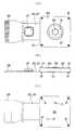
제 1 실시 형태는, 도 1 내지 도 7에 도시하는 바와 같이, 베이스 플레이트(10)와, 플렉시블 프린트 기판(20)과, 베이스(30)와, 위치 규제 스프링(40)과, 조작 부재(50)와, 커버 플레이트(60)로 이루어지는 것이다.1-7, the
상기 베이스 플레이트(10)는, 도 3 및 도 4에 도시하는 바와 같이, 평면 개략 사각형의 금속제 박판으로 이루어지는 것이고, 4구석에 코킹구멍(11)을 마련하고 있음과 함께, 대각선상에 치구구멍(治具孔)(12)을 마련하고 있다.As shown in Figs. 3 and 4, the
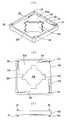
플렉시블 프린트 기판(20)은, 상기 베이스 플레이트(10)에 재치 가능한 개략 원형의 프린트 기판 본체부(21)로부터 리드부(22)를 연재한 것이다. 상기 프린트 기판 본체부(21)에는, 평면 개략 X자 형상의 돔 시트(23)가 접착 일체화되고, 그 중앙부에 중앙 누름버튼 스위치(24)가 형성되어 있음과 함께, 치구구멍(25)이 마련되어 있다. 또한, 상기 돔 시트(23)의 주변에는 홀 소자(26)가 실장되어 있다. 한편, 상기 리드부(22)에는 제어용 IC(27)가 탑재되어 있음과 함께, 그 자유단부에 접속부(28)가 형성되어 있다.The flexible printed circuit board 20 extends the
베이스(30)는, 도 5에 도시하는 바와 같이, 단면 개략 H자 형상을 가지며, 또한, 상기 베이스 플레이트(10)를 피복 가능한 평면 사각형상을 갖고 있다. 그리고, 상기 베이스(30)는, 그 표리면의 4구석에 코킹용 돌기(31)를 돌설하고 있는 한 편, 표리면에 형성한 오목개소(32a, 32b)의 구석에 후술하는 복귀 스프링을 걸어 맞춤하기 위한 관통 홈(33)을 형성하고 있다. 또한, 상기 오목개소(32a, 32b)의 중앙부에는 후술하는 조작 부재(50)를 끼워 맞춤하기 위한 끼워 맞춤구멍(34)을 마련하고 있음과 함께, 상기 끼워 맞춤구멍(34)의 외주 연부에 상기 홀 소자(26)에 끼워 맞춤하기 위한 노치부(35)를 형성하고 있다.As shown in FIG. 5, the
복귀 스프링(40)은, 도 6에 도시하는 바와 같이, 탄성 띠 모양재를 평면 개략 J자 형상으로 굴곡한 형상을 가지며, 일단부에 돌설한 걸어 맞춤돌기(41)를 상기 베이스(30)의 관통 홈(33)에 걸어 맞춤하여 위치 결정된다.As shown in FIG. 6, the
조작 부재(50)는, 원환형상 마그넷(55)을 조립한 홀더(51)와, 원판 플레이트(58)를 조립한 중앙 누름버튼(56)으로 구성되어 있다.The
홀더(51)는, 상기 베이스(30) 내에 위치 결정된 상기 복귀 스프링(40)의 사이에 배치 가능한 외경을 갖는 원판 형상이고, 그 중앙에 마련한 끼워 맞춤구멍(52)의 윗면 연부에 차양부(53)를 일체 성형하는 한편, 그 하면 연부에 고리형상 리브(54)를 돌설하고 있다. 그리고, 상기 끼워 맞춤구멍(52)에 원환형상 마그넷(55)을 끼워맞춤 일체화하고 있다. 또한, 상기 원환형상 마그넷은 N극, S극을 내외, 상하, 또는, 전후 교대의 어느 하나로 배치하고 있다.The
중앙 누름버튼(56)은 상기 원환형상 마그넷 내에 끼워맞춤 가능한 외경을 갖는 원주 형상이고, 그 저면에 조작용 돌기(57)를 갖고 있다. 그리고, 상기 조작용 돌기(57)에는, 자성재로 이루어지는 동심원형상의 원판 플레이트(58)를 끼워맞춤 일체화하고 있다. 이 때문에, 상기 원환형상 마그넷(55) 내에 중앙 누름버튼(56)을 조립하면, 상기 원판 플레이트(58)가 원환형상 마그넷(55)에 분리 가능하게 흡착 일체화하고, 중앙 누름버튼(56)을 위치 규제한다.The
커버 플레이트(60)는, 상기 베이스(30)를 피복 가능한 평면 개략 사각형의 금속제 박판으로 이루어지고, 그 중앙에 상기 조작 부재(50)를 빠짐방지할 수 있는 직경의 조작구멍(61)을 갖음과 함께, 그 4구석에 코킹구멍(62)을 마련하고 있다.The
다음에, 전술한 구성 부품으로 이루어지는 입력 장치의 조립 방법에 관해 설명한다.Next, the assembling method of the input device which consists of the above-mentioned components is demonstrated.
우선, 베이스 플레이트(10)의 치구구멍(12)에 도시하지 않은 치구인 한 쌍의 위치 결정 핀을 삽입하여 위치 결정한다. 그리고, 홀 소자(26) 등을 실장하고, 또한, 이면(裏面)에 접착재를 도포한 플렉시블 프린트 기판(20)의 치구구멍(25)을 상기 위치 결정 핀에 삽입하고, 베이스 플레이트(10)에 접착 일체화한다.First, a pair of positioning pins, which are not shown, is inserted into the
그리고, 상기 베이스 플레이트(10)의 코킹구멍(11)에 베이스(30)의 코킹용 돌기(31)를 끼워 맞춤하여 코킹 고정한다. 계속해서, 상기 베이스(30)의 관통 홈(33)에 복귀 스프링(40)의 걸어 맞춤용 돌기(41)를 끼워 맞춤하여 위치 결정한다. 또한, 홀더(51)의 끼워 맞춤구멍(52)에 원환형상 마그넷(55)을 끼워맞춤 일체화하는 한편, 상기 중앙 누름버튼(56)의 조작용 돌기(57)에 원판 플레이트(58)를 끼워맞춤 일체화한다. 그리고, 상기 원환 마그넷(55) 내에 상기 중앙 누름버튼(56)을 끼워 맞춤하고 조립함에 의해, 상기 원환형상 마그넷(55)에 원판 플레이트(58)를 흡착 일체화시킨다.The
계속해서, 베이스(30) 내에 대향하도록 위치 결정한 복귀 스프링(40)의 사이 에, 상기 조작 부재(50)를 위치 결정하고, 그 고리형상 리브(54)를 베이스(30)의 끼워 맞춤구멍(34)에 끼워 맞춤하여 조립한다. 최후로, 상기 베이스(30)의 코킹용 돌기(31)에 커버 플레이트(60)의 코킹구멍(62)을 끼워 맞춤하고, 코킹 고정한다.Subsequently, the
다음에, 전술한 입력 장치를 휴대 전화기에 조립한 경우의 조작 방법에 관해 설명한다.Next, a description will be given of an operation method in the case where the above-described input device is assembled into a cellular phone.
우선, 조작 부재(50)를 슬라이드 이동시키거나, 또는, 회동시키면, 이에 일체인 원환형상 마그넷(55)도 슬라이드 이동하고, 또는, 회동한다. 이 때문에, 홀 소자(26)가 자력의 변화를 검지하고, 이에 의거하여 조작 부재(50)의 이동량, 회동 방향, 회동량을 검출한다.First, when the
그리고, 그 검출 결과가 도시하지 않은 제어 회로를 통하여 모니터의 화면 표시된 스크롤 바의 이동 또는 모니터 화면 표시를 상하 또는 좌우에 이동시킨다. 계속해서, 소망하는 위치에 스크롤 바가 도달한 경우에, 중앙 누름버튼(56)을 누름에 의해, 중앙 누름버튼 스위치(24) 내의 반전 스프링이 반전하고, 대응하는 중앙 도전부를 도통시켜서 선택 지령을 출력한다.Then, the detection result does not move the scroll bar displayed on the monitor screen or the monitor screen display up or down or left and right through a control circuit not shown. Subsequently, when the scroll bar reaches the desired position, by pressing the
계속해서, 중앙 누름버튼(56)으로부터 조작력을 해제하면, 상기 중앙 누름버튼 스위치(24) 내의 반전 스프링이 복귀함과 함께, 조작 부재(50)가 복귀 스프링(40)의 스프링력으로 원래의 위치로 자동 복귀한다.Subsequently, when the operation force is released from the
본 실시 형태에 관한 조작 부재(50)에서는, 중앙 누름버튼(56)에 일체화한 원판 플레이트(58)가, 홀더(51)에 일체화한 원환형상 마그넷(55)에 분리 가능하게 흡착 일체화한다. 이 때문에, 입력 장치를 박형화, 소형화할 수 있을 뿐만 아니라, 상기 중앙 누름버튼(56)에 기울어짐이나 덜커덕거림이 생기지 않고, 외부 진동 등에 의한 이상한 음도 생기지 않는다. 또한, 전술과 같은 부적합함도 생기지 않기 때문에, 구성 부품을 높은 치수 정밀도로 제조, 조립할 필요가 없어지고, 생산성이 향상하고, 수율이 향상한다는 이점이 있다.In the
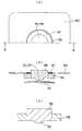
제 2 실시 형태는, 도 8에 도시하는 바와 같이, 중앙 누름버튼(56)과 원판 플레이트부(58a)를 자성재로 일체 성형한 경우이다.As shown in FIG. 8, 2nd Embodiment is the case where the
본 실시 형태에 의하면, 부품 갯수, 조립공수가 감소하고, 생산성이 향상한다는 이점이 있다.According to the present embodiment, there is an advantage that the number of parts and the number of assembly work are reduced, and the productivity is improved.
전술한 제 1, 제 2 실시 형태에서는, 원판 플레이트부(58a)의 극성을 원환형상 마그넷(55)과 동일한 극성으로 함에 의해, 그 반발력을 이용하여 중앙 누름버튼(56)을 위치 규제하고, 기울어짐, 덜커덕거림을 방지하여도 좋다.In the above-described first and second embodiments, the polarity of the
제 3 실시 형태는, 도 9에 도시하는 바와 같이, 중앙 누름버튼(56)에 원환형상 마그넷(55)을 일체에 조립하는 한편, 커버 플레이트(60)를 자성재로 형성하고, 상기 원환형상 마그넷(55)을 흡착시키는 경우이다.In the third embodiment, as shown in FIG. 9, the
본 실시 형태에 의하면, 홀더가 불필요하게 되어, 부품 갯수, 조립공수가 감소하고, 생산성이 향상함과 함께, 입력 장치를 보다 한층 박형화, 소형화할 수 있다는 이점이 있다.According to the present embodiment, there is an advantage that the holder is not necessary, the number of parts and the number of assembly operations are reduced, the productivity is improved, and the input device can be further thinned and downsized.
제 4 실시 형태는, 도 10에 도시하는 바와 같이, 마그넷으로 이루어지는 중앙 누름버튼(56)과 원환형상부(55a)를 일체 성형한 경우이다.As shown in FIG. 10, 4th Embodiment is the case where the
본 실시 형태에 의하면, 부품 갯수, 조립공수가 감소하고, 생산성이 향상함 과 함께, 입력 장치를 보다 한층 박형화, 소형화할 수 있다는 이점이 있다.According to the present embodiment, there are advantages in that the number of parts and the number of assembly operations are reduced, the productivity is improved, and the input device can be further thinned and downsized.
또한, 전술한 제 3, 제 4 실시 형태에서는, 커버 플레이트(60)와 원환형상 마그넷 부(55a)를 동일한 극성으로 하고, 그 반발력을 이용하여 중앙 누름버튼(56)을 위치 규제하여도 좋다.In addition, in the above-mentioned third and fourth embodiments, the
산업상의 이용 가능성Industrial availability
본 발명에서는 휴대 전화기에 적용한 경우에 관해 설명하였지만, PC 등의 다른 전자 기기에 적용하여도 좋음은 물론이다.Although the present invention has been described in the case where the present invention is applied to a mobile phone, of course, the present invention may be applied to other electronic devices such as a PC.
도 1의 A, B 및 C는 본 발명에 관한 입력 장치의 제 1 실시 형태를 도시하는 평면도, 정면도 및 저면도.A, B, and C of FIG. 1 are a plan view, a front view, and a bottom view showing a first embodiment of an input device according to the present invention.
도 2의 A 및 B는 도 1에서 도시한 입력 장치의 부분 확대 평면도 및 단면도.2A and 2B are partially enlarged plan views and cross-sectional views of the input device shown in FIG. 1.
도 3은 도 1에서 도시한 입력 장치의 상방에서 본 분해 사시도.3 is an exploded perspective view seen from above of the input device shown in FIG. 1;
도 4는 도 1에서 도시한 입력 장치의 하방에서 본 분해 사시도.4 is an exploded perspective view of the input device illustrated in FIG. 1 as viewed from below.
도 5의 A, B 및 C는 도 3에서 도시한 베이스의 사시도, 평면도 및 정면도.A, B and C of FIG. 5 are a perspective view, a plan view and a front view of the base shown in FIG.
도 6의 A, B 및 C는 도 3에서 도시한 복귀 스프링의 평면도, 정면도 및 사시도.6 A, B and C are a plan view, a front view and a perspective view of the return spring shown in FIG.
도 7의 A, B 및 C는 도 1에서 도시한 입력 장치를 도시하는 부분 평면도, 단면도, 부분 확대 단면도.A, B, and C of FIG. 7 are a partial plan view, a sectional view, and a partially enlarged sectional view showing the input device shown in FIG.
도 8의 A, B 및 C는 입력 장치의 제 2 실시 형태를 도시하는 부분 평면도, 단면도, 부분 확대 단면도.A, B, and C in FIG. 8 are a partial plan view, a sectional view, and a partially enlarged sectional view showing a second embodiment of the input device.
도 9의 A, B 및 C는 입력 장치의 제 3 실시 형태를 도시하는 부분 평면도, 단면도, 부분 확대 단면도.A, B, and C in FIG. 9 are a partial plan view, a cross-sectional view, and a partially enlarged cross-sectional view showing a third embodiment of the input device.
도 10의 A, B 및 C는 입력 장치의 제 4 실시 형태를 도시하는 부분 평면도, 단면도, 부분 확대 단면도.A, B, and C of FIG. 10 are a partial plan view, a sectional view, and a partially enlarged sectional view showing a fourth embodiment of an input device.
(도면의 주요 부분에 대한 부호의 설명)(Explanation of symbols for the main parts of the drawing)
10 : 베이스 플레이트20 : 플렉시블 프린트 기판10 base plate 20 flexible printed circuit board
24 : 중앙 누름버튼 스위치26 : 홀 소자24: center pushbutton switch 26: Hall element
30 : 베이스33 : 관통 홈30: base 33: through groove
34 : 끼워 맞춤구멍40 : 복귀 스프링34: fitting hole 40: return spring
50 : 조작 부재51 : 홀더50: operation member 51: holder
52 : 끼워 맞춤구멍53 : 차양부52: fitting hole 53: shade
55 : 원환형상 마그넷56 : 중앙 누름버튼55: annular magnet 56: center push button
57 : 원판 플레이트60 : 커버 플레이트57: disc plate 60: cover plate
Claims (7)
Translated fromKoreanApplications Claiming Priority (2)
| Application Number | Priority Date | Filing Date | Title |
|---|---|---|---|
| JP2008247358AJP5098928B2 (en) | 2008-09-26 | 2008-09-26 | INPUT DEVICE AND ELECTRONIC DEVICE USING THE SAME |
| JPJP-P-2008-247358 | 2008-09-26 |
Publications (2)
| Publication Number | Publication Date |
|---|---|
| KR20100035588A KR20100035588A (en) | 2010-04-05 |
| KR101070484B1true KR101070484B1 (en) | 2011-10-05 |
Family
ID=42056769
Family Applications (1)
| Application Number | Title | Priority Date | Filing Date |
|---|---|---|---|
| KR1020090087015AExpired - Fee RelatedKR101070484B1 (en) | 2008-09-26 | 2009-09-15 | Input device and electronic apparatus using same |
Country Status (3)
| Country | Link |
|---|---|
| US (1) | US8143981B2 (en) |
| JP (1) | JP5098928B2 (en) |
| KR (1) | KR101070484B1 (en) |
Families Citing this family (35)
| Publication number | Priority date | Publication date | Assignee | Title |
|---|---|---|---|---|
| KR101156937B1 (en)* | 2010-10-11 | 2012-06-14 | 주식회사 이노칩테크놀로지 | Multi-direction input device |
| KR20120049630A (en)* | 2010-11-09 | 2012-05-17 | 주식회사 이노칩테크놀로지 | Multi-direction input device |
| US9753436B2 (en)* | 2013-06-11 | 2017-09-05 | Apple Inc. | Rotary input mechanism for an electronic device |
| KR20240065191A (en)* | 2013-06-11 | 2024-05-14 | 애플 인크. | Wearable electronic device |
| EP3014400B1 (en) | 2013-08-09 | 2020-06-03 | Apple Inc. | Tactile switch for an electronic device |
| JP6226425B2 (en)* | 2014-01-31 | 2017-11-08 | アルプス電気株式会社 | Rotation input device |
| US10048802B2 (en) | 2014-02-12 | 2018-08-14 | Apple Inc. | Rejection of false turns of rotary inputs for electronic devices |
| CN105374609B (en)* | 2014-07-14 | 2018-12-11 | 富士康(昆山)电脑接插件有限公司 | Multi-direction switch device |
| US10190891B1 (en) | 2014-07-16 | 2019-01-29 | Apple Inc. | Optical encoder for detecting rotational and axial movement |
| KR20250021617A (en) | 2014-09-02 | 2025-02-13 | 애플 인크. | Wearable electronic device |
| US20160172136A1 (en)* | 2014-09-22 | 2016-06-16 | Polara Engineering, Inc. | Hall effect pushbutton switch |
| TWM502309U (en)* | 2015-02-03 | 2015-06-01 | Apix Inc | Adjustable supporting frame apparatus |
| KR20160104950A (en) | 2015-02-27 | 2016-09-06 | 삼성전자주식회사 | Inputting device, electronic device and method amd apparatus for controlling thereof |
| KR20160104935A (en) | 2015-02-27 | 2016-09-06 | 삼성전자주식회사 | Method for controlling a sensing devices of rotation member and electronic device thereof |
| WO2016141228A1 (en) | 2015-03-05 | 2016-09-09 | Apple Inc. | Optical encoder with direction-dependent optical properties |
| EP3251139B1 (en) | 2015-03-08 | 2021-04-28 | Apple Inc. | Compressible seal for rotatable and translatable input mechanisms |
| US10018966B2 (en) | 2015-04-24 | 2018-07-10 | Apple Inc. | Cover member for an input mechanism of an electronic device |
| KR20170023492A (en)* | 2015-08-24 | 2017-03-06 | 엘지전자 주식회사 | Electronic device |
| US9891651B2 (en) | 2016-02-27 | 2018-02-13 | Apple Inc. | Rotatable input mechanism having adjustable output |
| US10551798B1 (en) | 2016-05-17 | 2020-02-04 | Apple Inc. | Rotatable crown for an electronic device |
| US10061399B2 (en) | 2016-07-15 | 2018-08-28 | Apple Inc. | Capacitive gap sensor ring for an input device |
| US10019097B2 (en) | 2016-07-25 | 2018-07-10 | Apple Inc. | Force-detecting input structure |
| US10664074B2 (en) | 2017-06-19 | 2020-05-26 | Apple Inc. | Contact-sensitive crown for an electronic watch |
| US10962935B1 (en) | 2017-07-18 | 2021-03-30 | Apple Inc. | Tri-axis force sensor |
| US11360440B2 (en) | 2018-06-25 | 2022-06-14 | Apple Inc. | Crown for an electronic watch |
| US11561515B2 (en) | 2018-08-02 | 2023-01-24 | Apple Inc. | Crown for an electronic watch |
| US11181863B2 (en) | 2018-08-24 | 2021-11-23 | Apple Inc. | Conductive cap for watch crown |
| US12259690B2 (en) | 2018-08-24 | 2025-03-25 | Apple Inc. | Watch crown having a conductive surface |
| CN211293787U (en) | 2018-08-24 | 2020-08-18 | 苹果公司 | Electronic watch |
| CN209625187U (en) | 2018-08-30 | 2019-11-12 | 苹果公司 | Electronic Watches and Electronic Devices |
| US11194298B2 (en) | 2018-08-30 | 2021-12-07 | Apple Inc. | Crown assembly for an electronic watch |
| US11194299B1 (en) | 2019-02-12 | 2021-12-07 | Apple Inc. | Variable frictional feedback device for a digital crown of an electronic watch |
| US11550268B2 (en) | 2020-06-02 | 2023-01-10 | Apple Inc. | Switch module for electronic crown assembly |
| US12092996B2 (en) | 2021-07-16 | 2024-09-17 | Apple Inc. | Laser-based rotation sensor for a crown of an electronic watch |
| US12189347B2 (en) | 2022-06-14 | 2025-01-07 | Apple Inc. | Rotation sensor for a crown of an electronic watch |
Citations (1)
| Publication number | Priority date | Publication date | Assignee | Title |
|---|---|---|---|---|
| KR100847652B1 (en)* | 2003-01-20 | 2008-07-21 | 아사히 가세이 일렉트로닉스 가부시끼가이샤 | Pointing device |
Family Cites Families (21)
| Publication number | Priority date | Publication date | Assignee | Title |
|---|---|---|---|---|
| US4459578A (en)* | 1983-01-13 | 1984-07-10 | Atari, Inc. | Finger control joystick utilizing Hall effect |
| EP0477098B1 (en)* | 1990-09-18 | 1996-06-26 | Fujitsu Limited | Cursor displacement control device for a computer display |
| KR100285822B1 (en)* | 1994-12-28 | 2001-04-16 | 후나키 토시유키 | Thin switch unit and switch attachment indicator |
| US5714980A (en)* | 1995-10-31 | 1998-02-03 | Mitsumi Electric Co., Ltd. | Pointing device |
| JP2002091691A (en)* | 2000-09-20 | 2002-03-29 | Nagano Fujitsu Component Kk | Pointing device |
| JP2002007059A (en)* | 2000-06-27 | 2002-01-11 | Nagano Fujitsu Component Kk | Device for inputting coordinates |
| JP3954784B2 (en) | 2000-08-22 | 2007-08-08 | アルプス電気株式会社 | Multi-directional input device |
| JP2002149336A (en)* | 2000-11-09 | 2002-05-24 | Nagano Fujitsu Component Kk | Coordinate input device |
| JP4122045B2 (en)* | 2001-01-19 | 2008-07-23 | 富士通コンポーネント株式会社 | pointing device |
| JP4121730B2 (en)* | 2001-01-19 | 2008-07-23 | 富士通コンポーネント株式会社 | Pointing device and portable information device |
| US6612404B2 (en)* | 2001-05-25 | 2003-09-02 | Thyssen Elevator Capital Corp. | Contactless hall effect push button switch |
| ES1049932Y (en)* | 2001-08-21 | 2002-06-01 | Lorenzo Ind Sa | MULTIDIRECTIONAL COMMAND ORGAN. |
| DE10212929A1 (en)* | 2002-03-19 | 2003-10-02 | Ego Elektro Geraetebau Gmbh | Control device for an electrical device |
| JP4308559B2 (en)* | 2003-03-20 | 2009-08-05 | ポリマテック株式会社 | Slide input keypad and slide input switch |
| JP4495525B2 (en)* | 2004-06-01 | 2010-07-07 | 旭化成エレクトロニクス株式会社 | Key sheet for pointing device and pointing device |
| JP4100409B2 (en)* | 2005-04-01 | 2008-06-11 | オムロン株式会社 | Operation input device and electronic apparatus using the same |
| KR100655878B1 (en)* | 2006-02-22 | 2006-12-08 | 삼성전기주식회사 | Rotary input device |
| US7417422B2 (en)* | 2006-03-22 | 2008-08-26 | Samsung Electro-Mechanics Co., Ltd. | Rotary manipulation type input apparatus |
| JP4684217B2 (en)* | 2006-12-19 | 2011-05-18 | ホシデン株式会社 | Multi-directional input device |
| JP2009104877A (en)* | 2007-10-23 | 2009-05-14 | Polymatech Co Ltd | Slide operation type key sheet and key switch |
| JP5262254B2 (en)* | 2008-04-09 | 2013-08-14 | 日本電気株式会社 | Analog pointing key structure |
- 2008
- 2008-09-26JPJP2008247358Apatent/JP5098928B2/ennot_activeExpired - Fee Related
- 2009
- 2009-09-15KRKR1020090087015Apatent/KR101070484B1/ennot_activeExpired - Fee Related
- 2009-09-25USUS12/567,144patent/US8143981B2/ennot_activeExpired - Fee Related
Patent Citations (1)
| Publication number | Priority date | Publication date | Assignee | Title |
|---|---|---|---|---|
| KR100847652B1 (en)* | 2003-01-20 | 2008-07-21 | 아사히 가세이 일렉트로닉스 가부시끼가이샤 | Pointing device |
Also Published As
| Publication number | Publication date |
|---|---|
| US8143981B2 (en) | 2012-03-27 |
| JP2010080263A (en) | 2010-04-08 |
| US20100079225A1 (en) | 2010-04-01 |
| KR20100035588A (en) | 2010-04-05 |
| JP5098928B2 (en) | 2012-12-12 |
Similar Documents
| Publication | Publication Date | Title |
|---|---|---|
| KR101070484B1 (en) | Input device and electronic apparatus using same | |
| KR101022964B1 (en) | Operation input device and electronic device using the same | |
| KR101022858B1 (en) | Operation input device and electronic device using the same | |
| JP4737197B2 (en) | Operation input device and electronic apparatus using the same | |
| US8508511B2 (en) | Inputting device | |
| KR100801809B1 (en) | Operation input device and electronic device using the same | |
| KR100931434B1 (en) | Operation input device and electronic device using the same | |
| JP4301312B2 (en) | Operation input device and electronic apparatus using the same | |
| KR100920290B1 (en) | Operation input device and electronic instrument of use thereof | |
| JP4624306B2 (en) | Multi-directional input device | |
| JP2006100084A (en) | Multi-directional operation device | |
| JP5338592B2 (en) | Operation input device and electronic apparatus using the same | |
| KR20100081266A (en) | Operation input device | |
| KR100951517B1 (en) | An input device and an electronic device having the input device | |
| KR20090122132A (en) | Input device and electronic device equipped with the input device | |
| JP2007299037A (en) | Coordinate input device | |
| WO2010095492A1 (en) | Multidirectional input device and electronic device using the same | |
| JP4920527B2 (en) | Multi-directional input device | |
| JP2011164846A (en) | Input device and information terminal apparatus | |
| JP2009283402A (en) | Sheet-form switch | |
| KR20100130338A (en) | Information input device | |
| JP2007250289A (en) | Terminal device | |
| JP2012027786A (en) | Input device and electronic equipment |
Legal Events
| Date | Code | Title | Description |
|---|---|---|---|
| A201 | Request for examination | ||
| PA0109 | Patent application | St.27 status event code:A-0-1-A10-A12-nap-PA0109 | |
| PA0201 | Request for examination | St.27 status event code:A-1-2-D10-D11-exm-PA0201 | |
| PG1501 | Laying open of application | St.27 status event code:A-1-1-Q10-Q12-nap-PG1501 | |
| D13-X000 | Search requested | St.27 status event code:A-1-2-D10-D13-srh-X000 | |
| D14-X000 | Search report completed | St.27 status event code:A-1-2-D10-D14-srh-X000 | |
| E902 | Notification of reason for refusal | ||
| PE0902 | Notice of grounds for rejection | St.27 status event code:A-1-2-D10-D21-exm-PE0902 | |
| P11-X000 | Amendment of application requested | St.27 status event code:A-2-2-P10-P11-nap-X000 | |
| P13-X000 | Application amended | St.27 status event code:A-2-2-P10-P13-nap-X000 | |
| E701 | Decision to grant or registration of patent right | ||
| PE0701 | Decision of registration | St.27 status event code:A-1-2-D10-D22-exm-PE0701 | |
| GRNT | Written decision to grant | ||
| PR0701 | Registration of establishment | St.27 status event code:A-2-4-F10-F11-exm-PR0701 | |
| PR1002 | Payment of registration fee | St.27 status event code:A-2-2-U10-U11-oth-PR1002 Fee payment year number:1 | |
| PG1601 | Publication of registration | St.27 status event code:A-4-4-Q10-Q13-nap-PG1601 | |
| LAPS | Lapse due to unpaid annual fee | ||
| PC1903 | Unpaid annual fee | St.27 status event code:A-4-4-U10-U13-oth-PC1903 Not in force date:20140929 Payment event data comment text:Termination Category : DEFAULT_OF_REGISTRATION_FEE | |
| PC1903 | Unpaid annual fee | St.27 status event code:N-4-6-H10-H13-oth-PC1903 Ip right cessation event data comment text:Termination Category : DEFAULT_OF_REGISTRATION_FEE Not in force date:20140929 | |
| P22-X000 | Classification modified | St.27 status event code:A-4-4-P10-P22-nap-X000 | |
| R18-X000 | Changes to party contact information recorded | St.27 status event code:A-5-5-R10-R18-oth-X000 |