KR101070049B1 - Surgical instrument - Google Patents
Surgical instrumentDownload PDFInfo
- Publication number
- KR101070049B1 KR101070049B1KR1020090039091AKR20090039091AKR101070049B1KR 101070049 B1KR101070049 B1KR 101070049B1KR 1020090039091 AKR1020090039091 AKR 1020090039091AKR 20090039091 AKR20090039091 AKR 20090039091AKR 101070049 B1KR101070049 B1KR 101070049B1
- Authority
- KR
- South Korea
- Prior art keywords
- body portion
- hinge
- surgical instrument
- camera
- tip
- Prior art date
- Legal status (The legal status is an assumption and is not a legal conclusion. Google has not performed a legal analysis and makes no representation as to the accuracy of the status listed.)
- Expired - Fee Related
Links
Images


Classifications
- A—HUMAN NECESSITIES
- A61—MEDICAL OR VETERINARY SCIENCE; HYGIENE
- A61B—DIAGNOSIS; SURGERY; IDENTIFICATION
- A61B17/00—Surgical instruments, devices or methods
- A61B17/28—Surgical forceps
- A61B17/2812—Surgical forceps with a single pivotal connection
- A—HUMAN NECESSITIES
- A61—MEDICAL OR VETERINARY SCIENCE; HYGIENE
- A61B—DIAGNOSIS; SURGERY; IDENTIFICATION
- A61B17/00—Surgical instruments, devices or methods
- A61B17/28—Surgical forceps
- A—HUMAN NECESSITIES
- A61—MEDICAL OR VETERINARY SCIENCE; HYGIENE
- A61B—DIAGNOSIS; SURGERY; IDENTIFICATION
- A61B1/00—Instruments for performing medical examinations of the interior of cavities or tubes of the body by visual or photographical inspection, e.g. endoscopes; Illuminating arrangements therefor
- A61B1/04—Instruments for performing medical examinations of the interior of cavities or tubes of the body by visual or photographical inspection, e.g. endoscopes; Illuminating arrangements therefor combined with photographic or television appliances
- A61B1/05—Instruments for performing medical examinations of the interior of cavities or tubes of the body by visual or photographical inspection, e.g. endoscopes; Illuminating arrangements therefor combined with photographic or television appliances characterised by the image sensor, e.g. camera, being in the distal end portion
- A—HUMAN NECESSITIES
- A61—MEDICAL OR VETERINARY SCIENCE; HYGIENE
- A61M—DEVICES FOR INTRODUCING MEDIA INTO, OR ONTO, THE BODY; DEVICES FOR TRANSDUCING BODY MEDIA OR FOR TAKING MEDIA FROM THE BODY; DEVICES FOR PRODUCING OR ENDING SLEEP OR STUPOR
- A61M27/00—Drainage appliance for wounds or the like, i.e. wound drains, implanted drains
- A—HUMAN NECESSITIES
- A61—MEDICAL OR VETERINARY SCIENCE; HYGIENE
- A61B—DIAGNOSIS; SURGERY; IDENTIFICATION
- A61B17/00—Surgical instruments, devices or methods
- A61B17/32—Surgical cutting instruments
- A61B17/3201—Scissors
- A—HUMAN NECESSITIES
- A61—MEDICAL OR VETERINARY SCIENCE; HYGIENE
- A61B—DIAGNOSIS; SURGERY; IDENTIFICATION
- A61B90/00—Instruments, implements or accessories specially adapted for surgery or diagnosis and not covered by any of the groups A61B1/00 - A61B50/00, e.g. for luxation treatment or for protecting wound edges
- A61B90/30—Devices for illuminating a surgical field, the devices having an interrelation with other surgical devices or with a surgical procedure
- A61B2090/306—Devices for illuminating a surgical field, the devices having an interrelation with other surgical devices or with a surgical procedure using optical fibres
- A—HUMAN NECESSITIES
- A61—MEDICAL OR VETERINARY SCIENCE; HYGIENE
- A61B—DIAGNOSIS; SURGERY; IDENTIFICATION
- A61B2217/00—General characteristics of surgical instruments
- A61B2217/002—Auxiliary appliance
- A61B2217/005—Auxiliary appliance with suction drainage system
- A—HUMAN NECESSITIES
- A61—MEDICAL OR VETERINARY SCIENCE; HYGIENE
- A61B—DIAGNOSIS; SURGERY; IDENTIFICATION
- A61B90/00—Instruments, implements or accessories specially adapted for surgery or diagnosis and not covered by any of the groups A61B1/00 - A61B50/00, e.g. for luxation treatment or for protecting wound edges
- A61B90/36—Image-producing devices or illumination devices not otherwise provided for
- A61B90/361—Image-producing devices, e.g. surgical cameras
- A—HUMAN NECESSITIES
- A61—MEDICAL OR VETERINARY SCIENCE; HYGIENE
- A61M—DEVICES FOR INTRODUCING MEDIA INTO, OR ONTO, THE BODY; DEVICES FOR TRANSDUCING BODY MEDIA OR FOR TAKING MEDIA FROM THE BODY; DEVICES FOR PRODUCING OR ENDING SLEEP OR STUPOR
- A61M1/00—Suction or pumping devices for medical purposes; Devices for carrying-off, for treatment of, or for carrying-over, body-liquids; Drainage systems
- A61M1/84—Drainage tubes; Aspiration tips
Landscapes
- Health & Medical Sciences (AREA)
- Life Sciences & Earth Sciences (AREA)
- Surgery (AREA)
- General Health & Medical Sciences (AREA)
- Public Health (AREA)
- Animal Behavior & Ethology (AREA)
- Veterinary Medicine (AREA)
- Engineering & Computer Science (AREA)
- Biomedical Technology (AREA)
- Heart & Thoracic Surgery (AREA)
- Nuclear Medicine, Radiotherapy & Molecular Imaging (AREA)
- Molecular Biology (AREA)
- Medical Informatics (AREA)
- Ophthalmology & Optometry (AREA)
- Radiology & Medical Imaging (AREA)
- Pathology (AREA)
- Optics & Photonics (AREA)
- Biophysics (AREA)
- Physics & Mathematics (AREA)
- Otolaryngology (AREA)
- Anesthesiology (AREA)
- Hematology (AREA)
- Endoscopes (AREA)
- Media Introduction/Drainage Providing Device (AREA)
- Surgical Instruments (AREA)
Abstract
Translated fromKorean
Description
Translated fromKorean본 발명은 수술 기구에 관한 것으로, 더욱 상세하게는 환자의 생체 조직을 박리하는 등의 수술에 사용하는 수술 기구에 관한 것이다.The present invention relates to a surgical instrument, and more particularly, to a surgical instrument used for surgery, such as peeling off the biological tissue of the patient.
일반적으로 외과 수술 중에는 연부 조직(soft tissue)을 박리(dissetion)하여 수술자(operator)가 원하는 수술 시야로 진입을 해야 하는 경우가 많다. 하지만 인체의 해부학적 구조상, 수술 부위를 수술자의 시야로 확인할 수 없어서 손 끝의 감각으로만 조직 박리를 시행해야 하는 위험한 상황을 피할 수 없게 되는 경우가 종종 발생한다. 그리하여, 시야가 확인되지 않는 조직을 박리하던 중에 출혈이 발생하면 단순압박지혈을 시도하여 출혈을 멈추게 할 수도 있지만, 지혈이 되지 않으면 환자에게 위험한 상황이 발생할 수 있다. 단순압박에 의해 지혈이 되었다 하더라도 출혈했던 조직에 다시 조작을 가할 경우 재 출혈 발생의 가능성이 높기 때문에, 수술자는 더 이상 조직 박리를 진행하기 어렵게 된다. 그리고, 최악의 경우에는 열악한 시야 때문에 수술의 목적과 직접 관련이 없는 중요한 타 장기의 손상을 유발할 수 있다. 이러한 결과들은 환자에게 수술 후 합병증이나 사망률을 증가시키는 원인이 된다.In general, during surgery, soft tissues are often detached to enter the desired surgical field of view by the operator. However, due to the anatomical structure of the human body, the surgical site cannot be identified by the operator's field of vision, and thus, a dangerous situation in which tissue detachment should be performed only by the sense of the fingertip is often avoided. Thus, if bleeding occurs while peeling tissues that are not visible, attempts to stop the bleeding by attempting simple compression hemostasis may result in dangerous situations for the patient. Even if hemostasis is caused by a simple compression, it is difficult for the operator to proceed with tissue detachment because the possibility of rebleeding is increased when the tissue is bleeded again. And in the worst case, poor vision can cause damage to other vital organs that are not directly related to the purpose of the surgery. These results may cause increased postoperative complications and mortality in patients.
본 발명은 상기와 같은 문제점을 해결하기 위하여 안출된 것으로서, 환자의 생체 조직 수술 시 육안으로 접근이 어려운 심도가 깊은 부위를 소형 카메라를 통해 모니터링 함으로써 수술 부위의 시야를 확보할 수 있도록 하는 수술 기구를 제공하는데 그 목적이 있다.The present invention has been made in order to solve the above problems, a surgical instrument that can ensure the field of view of the surgical site by monitoring a small depth of the deep area difficult to access the naked eye during surgery of the patient's biological tissues through a small camera The purpose is to provide.
본 발명의 다른 목적은 환자의 생체 조직 수술 시 어둡고 심도가 깊은 수술 부위에서 발생하는 출혈을 흡입하고 조명을 비추어 수술 부위의 시야를 확보함으로써 수술자가 안전하고 신속한 수술을 할 수 있도록 하는 수술 기구를 제공하는데 있다.It is another object of the present invention to provide a surgical instrument that allows the operator to perform a safe and rapid operation by inhaling bleeding occurring in a dark and deep surgical site and securing a field of view of the surgical site while illuminating the patient's living tissue. It is.
본 발명의 목적들은 이상에서 언급한 목적들로 제한되지 않으며, 언급되지 않은 또 다른 목적들은 아래의 기재로부터 당업자에게 명확하게 이해되어질 수 있을 것이다.The objects of the present invention are not limited to the above-mentioned objects, and other objects not mentioned can be clearly understood by those skilled in the art from the following description.
상기 목적을 달성하기 위한 본 발명의 바람직한 실시예에 따른 수술 기구는, 제 1 몸체부, 상기 제 1 몸체부와 대칭되는 형상을 가지는 제 2 몸체부, 상기 제 1 몸체부와 상기 제 2 몸체부가 교차되어 회전 가능하게 결합되는 힌지부, 및 상기 제 1 몸체부의 선단과 상기 제 2 몸체부의 선단 사이의 수술 부위를 촬영하기 위해 상기 힌지부에 구비되는 촬영부를 포함할 수 있다.Surgical instrument according to a preferred embodiment of the present invention for achieving the above object, a first body portion, a second body portion having a shape symmetrical with the first body portion, the first body portion and the second body portion And a hinge part intersected and rotatably coupled, and a photographing part provided in the hinge part to photograph a surgical site between the tip of the first body part and the tip of the second body part.
또한, 상기 힌지부는, 상기 제 1 몸체부와 상기 제 2 몸체부의 교차 회전부 위 사이에 위치하는 힌지몸체, 및 상기 힌지몸체의 상면과 하면에 돌출 형성되어 상기 제 1 몸체부와 상기 제 2 몸체부의 힌지홀에 각각 끼워져 힌지 결합되는 힌지축을 포함할 수 있다.The hinge portion may include a hinge body positioned between the first body portion and the second rotation portion of the second body portion, and a protrusion formed on an upper surface and a lower surface of the hinge body so as to protrude from the first body portion and the second body portion. It may include a hinge shaft which is fitted in each of the hinge holes and hinged.
또한, 상기 촬영부는 상기 힌지몸체의 전면 중앙에 렌즈가 노출되도록 내장되며, 촬영된 영상정보를 모니터에 전송하는 카메라를 포함할 수 있다.In addition, the photographing unit may be embedded to expose the lens in the front center of the hinge body, and may include a camera for transmitting the captured image information to the monitor.
여기서, 상기 카메라의 초점은 상기 제 1 몸체부의 선단과 상기 제 2 몸체부의 선단이 벌어진 사이의 중앙 부위를 지향하도록 배치되는 것이 바람직하다.Here, the focus of the camera is preferably disposed so as to direct the central portion between the front end of the first body portion and the front end of the second body portion.
본 발명의 수술 기구는, 상기 촬영부의 전방을 조명하기 위한 조명부를 더 포함할 수 있다.The surgical instrument of the present invention may further include an illumination unit for illuminating the front of the imaging unit.
또한, 상기 조명부는 상기 힌지부에 내장되며, 광원에서 발생하는 광을 광 전송하여 상기 촬영부의 전방을 조사하도록 가이드 하는 광섬유를 포함할 수 있다.In addition, the lighting unit may be embedded in the hinge portion, and may include an optical fiber guiding the light emitted from the light source to guide the front of the photographing unit.
여기서, 상기 광섬유의 선단은 상기 힌지부의 전면에 노출되며, 상기 촬영부를 기준으로 상하 또는 좌우에 대칭되게 배치되는 것이 바람직하다.Here, the front end of the optical fiber is exposed to the front surface of the hinge portion, it is preferable to be disposed symmetrically up and down or left and right with respect to the photographing unit.
또한, 상기 조명부는 상기 촬영부의 전방을 조사할 수 있도록 상기 힌지부의 전면에 상기 촬영부를 기준으로 상하 또는 좌우에 대칭되게 배치되는 전구 또는 LED 램프를 포함할 수 있다.In addition, the lighting unit may include a light bulb or an LED lamp disposed symmetrically in the up, down, left, and right directions with respect to the photographing unit on the front of the hinge unit to irradiate the front of the photographing unit.
또한, 본 발명의 수술 기구는 상기 제 1 몸체부와 상기 제 2 몸체부가 상기 힌지부를 중심으로 회전 시 상기 카메라의 초점이 상기 제 1 몸체부의 선단과 상기 제 2 몸체부의 선단이 벌어진 사이의 중앙을 항상 유지하도록 상기 카메라의 초점 위치를 가이드 하는 카메라 가이드부를 더 포함할 수 있다.In addition, the surgical instrument of the present invention is the focus of the camera when the first body portion and the second body portion is rotated about the hinge portion of the center between the distal end of the first body portion and the distal end of the second body portion The apparatus may further include a camera guide part that guides the focus position of the camera so that it is always maintained.
또한, 상기 카메라 가이드부는, 상기 힌지몸체의 후방으로 연장되게 형성되는 가이드로드, 상기 가이드로드의 후단에 회전 가능하게 결합되는 피니언, 및 상기 피니언과 맞물리도록 상기 제 1 몸체부와 상기 제 2 몸체부에 각각 구비되며 상기 제 1 몸체부와 상기 제 2 몸체부의 회전 시 상기 피니언을 회전시키면서 상기 가이드로드가 상기 제 1 몸체부와 상기 제 2 몸체부 사이의 중앙에 항상 위치하도록 하는 한 쌍의 랙을 포함할 수 있다.In addition, the camera guide portion, the guide rod is formed to extend to the rear of the hinge body, the pinion rotatably coupled to the rear end of the guide rod, and the first body portion and the second body portion to be engaged with the pinion. And a pair of racks provided at each of the guide rods so that the guide rod is always located at the center between the first body portion and the second body portion while the pinion is rotated when the first body portion and the second body portion are rotated. It may include.
또한, 본 발명의 수술 기구는 상기 제 1 몸체부 또는 상기 제 2 몸체부의 선단에 적어도 하나 형성되는 구멍을 통해 수술 중 환자의 출혈 부위에서 발생하는 혈액을 흡입하기 위한 흡입부와, 상기 구멍을 통해 유체를 공급하여 배출하기 위한 유체공급부를 더 포함할 수 있다. 여기서, 상기 구멍은 상기 제 1 몸체부 또는 상기 제 2 몸체부의 선단 전면 또는 내측면에 형성되는 것이 바람직하다.In addition, the surgical instrument of the present invention through the hole formed in at least one end of the first body portion or the second body portion through the suction portion for inhaling blood generated in the bleeding site of the patient during surgery, and through the hole The apparatus may further include a fluid supply unit for supplying and discharging the fluid. Here, the hole is preferably formed in the front end or the inner surface of the first body portion or the second body portion.
또한, 상기 구멍과 연결되도록 상기 제 1 몸체부 또는 상기 제 2 몸체부에 튜브관이 내장되고, 상기 튜브관은 상기 흡입부와 상기 유체공급부에 연결되는 것이 바람직하다.In addition, it is preferable that a tube tube is embedded in the first body portion or the second body portion so as to be connected to the hole, and the tube tube is connected to the suction portion and the fluid supply portion.
또한, 상기 튜브관과 상기 흡입부 및 유체공급부가 연결되는 부위에는 상기 흡입부에 의한 혈액 흡입과 상기 유체공급부에 의한 유체 공급을 선택적으로 스위칭 하는 스위칭 밸브가 구비되는 것이 바람직하다.In addition, it is preferable that a portion of the tube tube, the suction part and the fluid supply part are connected to a switching valve for selectively switching the blood suction by the suction part and the fluid supply by the fluid supply part.
또한, 상기 제 1 몸체부 또는 상기 제 2 몸체부의 내부에는 상기 튜브관이 삽입되어 내장될 수 있도록 튜브관 삽입홀이 길이방향으로 길게 형성되는 것이 바람직하다.In addition, it is preferable that the tube tube insertion hole is formed to be long in the longitudinal direction so that the tube tube is inserted into the first body portion or the second body portion.
또한, 상기 제 1 및 제 2 몸체부의 선단은 상향 또는 하향으로 벤딩되게 형성되는 것이 바람직하다.In addition, the front end of the first and second body portion is preferably formed to be bent upwards or downwards.
또한, 상기 제 1 및 제 2 몸체부의 후단에는 손가락을 끼워 파지할 수 있도록 손잡이부가 형성되는 것이 바람직하다.In addition, it is preferable that a handle part is formed at the rear end of the first and second body parts so as to hold a finger.
또한, 상기 제 1 몸체부와 상기 제 2 몸체부가 회전 시 상기 힌지몸체와 간섭이 발생하지 않도록 상기 제 1 몸체부와 상기 제 2 몸체부의 교차 회전 결합부위에는 상기 힌지몸체를 수용하는 힌지수용부가 각각 형성되는 것이 바람직하다.In addition, the hinge accommodating portion accommodating the hinge body is provided at the cross-rotating coupling portion of the first body portion and the second body portion so that the first body portion and the second body portion do not interfere with the hinge body when the second body portion rotates. It is preferably formed.
본 발명의 수술 기구는, 선단에 구멍이 적어도 하나 형성되는 제 1 몸체부, 상기 제 1 몸체부와 대칭되는 형상을 가지며 선단에 구멍이 적어도 하나 형성되는 제 2 몸체부, 상기 제 1 몸체부와 상기 제 2 몸체부가 교차되어 회전 가능하게 결합되는 힌지부, 상기 힌지부에 내장되며, 상기 제 1 몸체부의 선단과 상기 제 2 몸체부의 선단 사이의 수술 부위를 촬영하는 카메라, 상기 힌지부에 내장되며 광원에서 발생하는 광을 광 전송하여 상기 카메라의 전방을 조사하도록 가이드 하는 광섬유, 상기 제 1 몸체부와 상기 제 2 몸체부가 상기 힌지부를 중심으로 회전 시 상기 카메라의 초점이 상기 제 1 몸체부의 선단과 사이 제 2 몸체부의 선단이 벌어진 사이의 중앙을 항상 유지하도록 상기 카메라의 초점 위치를 가이드 하는 카메라 가이드부, 상기 제 1 몸체부 또는 상기 제 2 몸체부의 상기 구멍을 통해 수술 중 환자의 출혈 부위에서 발생하는 혈액을 흡입하기 위한 흡입부, 및 상기 제 1 몸체부 또는 상기 제 2 몸체부의 상기 구멍을 통해 유체를 공급하여 배출하기 위한 유체공급부를 포함할 수 있다.The surgical instrument of the present invention includes a first body portion having at least one hole formed at the tip, a second body portion having a shape symmetrical with the first body portion, and having at least one hole formed at the tip, and the first body portion. The second body portion is crossed and rotatably coupled to the hinge portion, embedded in the hinge portion, a camera for photographing the surgical site between the front end of the first body portion and the tip of the second body portion, is embedded in the hinge portion An optical fiber for guiding light emitted from a light source to irradiate the front of the camera, and when the first body part and the second body part rotate about the hinge part, the focus of the camera is at the front end of the first body part; A camera guide portion for guiding a focal position of the camera so that the front end of the second body portion is always maintained between the first and second body portions; The suction unit for sucking blood generated at the bleeding site of the patient during the operation through the hole of the second body portion, and for supplying and discharging fluid through the hole in the first body portion or the second body portion It may include a fluid supply.
기타 실시예들의 구체적인 사항들은 상세한 설명 및 도면들에 포함되어 있다.Specific details of other embodiments are included in the detailed description and the drawings.
상기한 바와 같은 본 발명의 수술 기구에 따르면, 환자의 생체 조직 수술 시 육안으로 접근이 어려운 심도가 깊은 부위를 소형 카메라를 통해 모니터링 함으로써 육안으로 접근이 어려운 심도가 깊은 수술 부위에 대해서도 수술 시야를 확보할 수 있다. 따라서, 생체 조직 박리 등과 같은 수술을 진행하면서 손상시키지 말아야 할 주요 혈관이나 중요 장기를 피해가면서 박리를 진행할 수 있게 되어 수술 위험도를 낮출 수 있다.According to the surgical instrument of the present invention as described above, the surgical field of view is secured even in the deep surgical region that is difficult to access the naked eye by monitoring the small depth of the deep region that is difficult to access the naked eye during surgery of the patient's biological tissue. can do. Therefore, it is possible to proceed with detachment while avoiding major blood vessels or important organs that should not be damaged while performing surgery such as biotissue detachment, thereby reducing the risk of surgery.
또한, 환자의 생체 조직 수술 시 어둡고 심도가 깊은 수술 부위에서 발생하는 출혈을 흡입하거나 출혈 부위의 세척 또는 약액 주입을 할 수 있으며, 조명을 비추어 수술 부위의 시야를 확보함으로써 수술자가 안전하고 신속한 수술을 할 수 있다.In addition, the patient can inhale the bleeding from the dark and deep surgical site, wash the bleeding site, or inject the medicinal solution during surgery on the patient's living tissue. can do.
또한, 기존 가위 형태의 수술 기구와 유사한 모양으로 제작되므로 수술자는 본 수술 기구의 사용 습득이 용이하다.In addition, the operator is easy to learn the use of the surgical instrument because it is made in a shape similar to the conventional surgical instruments.
본 발명의 효과들은 이상에서 언급한 효과들로 제한되지 않으며, 언급되지 않은 또 다른 효과들은 청구범위의 기재로부터 당업자에게 명확하게 이해될 수 있을 것이다.The effects of the present invention are not limited to the above-mentioned effects, and other effects not mentioned will be clearly understood by those skilled in the art from the description of the claims.
본 발명의 이점 및 특징, 그리고 그것들을 달성하는 방법은 첨부되는 도면과 함께 상세하게 후술되어 있는 실시예들을 참조하면 명확해질 것이다. 그러나 본 발명은 이하에서 개시되는 실시 예들에 한정되는 것이 아니라 서로 다른 다양한 형태로 구현될 수 있으며, 단지 본 실시예는 본 발명의 개시가 완전하도록 하고, 본 발명이 속하는 기술분야에서 통상의 지식을 가진 자에게 발명의 범주를 완전하게 알려주기 위해 제공되는 것이며, 본 발명은 청구항의 범주에 의해 정의될 뿐이다. 명세서 전체에 걸쳐 동일 참조 부호는 동일 구성요소를 지칭한다.BRIEF DESCRIPTION OF THE DRAWINGS The advantages and features of the present invention and the manner of achieving them will become apparent with reference to the embodiments described in detail below with reference to the accompanying drawings. However, the present invention is not limited to the embodiments disclosed below, but can be implemented in various different forms, only the embodiments are to make the disclosure of the present invention complete, and the general knowledge in the art to which the present invention belongs It is provided to fully convey the scope of the invention to those skilled in the art, and the present invention is defined only by the scope of the claims. Like reference numerals refer to like elements throughout.
이하, 첨부된 도면을 참조하여 본 발명의 바람직한 일 실시예에 따른 수술 기구를 상세히 설명하기로 한다. 참고로 본 발명을 설명함에 있어서 관련된 공지 기능 혹은 구성에 대한 구체적인 설명이 본 발명의 요지를 불필요하게 흐릴 수 있다고 판단되는 경우 그 상세한 설명을 생략한다.Hereinafter, with reference to the accompanying drawings will be described in detail the surgical instrument according to an embodiment of the present invention. In the following description, well-known functions or constructions are not described in detail to avoid unnecessarily obscuring the subject matter of the present invention.
본 발명에서 일관되게 사용하는 "박리(dissetion)" 란 적층된 생체 조직 사이 또는 이종 생체 조직 사이를 벌리는 작용을 말한다. 본 실시예에서는 적층된 생체 조직 사이 또는 이종 생체 조직 사이를 삐집고 들어가면서 조직 사이를 벌리는 생체 조직 박리기 형태의 수술 기구를 예시하였으나, 이에 한정되지 않고 박리기 이외의 형태를 가지는 다양한 수술 기구에도 적용이 가능하다.As used consistently in the present invention, "dissetion" refers to the action of spreading between stacked biological tissues or between heterologous biological tissues. In the present exemplary embodiment, a surgical instrument in the form of a biotissue exfoliator that spreads between tissues while pitting between stacked biological tissues or between heterogeneous biological tissues is illustrated. This is possible.
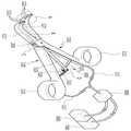
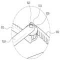
도 1은 본 발명의 일 실시예에 따른 수술 기구를 개략적으로 도시한 사시도이고, 도 2 및 도3은 수술 기구의 선단부가 닫힌 상태와 벌려진 상태를 각각 도시한 평면도이고, 도 4는 도 1에 나타낸 수술 기구의 분해 사시도이고, 도 5는 도 4에 나타낸 제 1 몸체부의 Ⅴ-Ⅴ선에 따른 단면도이고, 도 6 내지 도 9는 도 1의 A, B, C 및 B부분을 각각 확대 도시한 사시도이며, 도 10은 수술 기구에 내장된 카메 라의 초점 위치를 도시한 예시도이다.1 is a perspective view schematically showing a surgical instrument according to an embodiment of the present invention, Figures 2 and 3 are a plan view showing a state in which the leading end of the surgical instrument is closed and open, respectively, Figure 4 is a 5 is a cross-sectional view taken along line V-V of the first body part shown in FIG. 4, and FIGS. 6 to 9 are enlarged views of parts A, B, C, and B of FIG. 10 is a perspective view illustrating an example of a focal position of a camera embedded in a surgical instrument.
도 1 내지 도 10에 도시된 바와 같이, 본 발명의 일 실시예에 따른 수술 기구는 제 1 몸체부(110), 제 2 몸체부(120), 힌지부(200), 촬영부(300), 조명부(400), 카메라 가이드부(500), 흡입부(600) 및 유체공급부(700) 등을 포함할 수 있다.As shown in Figure 1 to 10, the surgical instrument according to an embodiment of the present invention, the
본 발명의 수술 기구는 전체적으로 가위와 비슷한 형상을 가지는 조직 박리기로 구성될 수 있다.The surgical instrument of the present invention may be composed of a tissue exfoliator having a shape similar to scissors as a whole.
제 1 몸체부(110)와 제 2 몸체부(120)는 한 쌍으로 구성되어 전체적으로는 가위 형상을 가지는 수술 기구의 일측과 타측 몸체에 각각 해당하며, 바람직하게는 제 1 몸체부(110)와 제 2 몸체부(120)는 서로 대칭되는 형상을 가진다.The
제 1 몸체부(110)와 제 2 몸체부(120)는 대략 중앙 부위에서 서로 교차되어 후술할 힌지부(200)에 의해 회전 가능하게 결합된다. 이때, 제 1 몸체부(110)와 제 2 몸체부(120)는 교차 회전하는 부위에 후술할 힌지몸체(210)의 상면과 하면에 각각 돌출 형성된 한 쌍의 힌지축(221,222)이 끼워지도록 힌지홀(116,126)에 각각 형성될 수 있다.The
제 1 몸체부(110)와 제 2 몸체부(120)는 생체 조직 박리를 시행 시 출혈된 또는 출혈 중인 혈액 또는 이물질 등을 흡입하거나 출혈부위를 세척 또는 소독 등을 위한 유체(물 또는 약액)를 배출하기 위해 각각의 선단에 적어도 하나의 구멍(111,121)이 형성된다. 예를 들어, 본 실시예에서는 구멍(111,121)이 제 1 몸체부(110)와 제 2 몸체부(120)의 각각 선단 전면에 1개(111a)(121a), 그리고 내측면 에 2~3개(111b,111c,111d)(121b,121c,121d) 정도 형성되는 구성을 예시하였으나, 이에 한정되지 않고 다양한 개수와 형상을 가질 수 있으며, 제 1 몸체부(110)의 선단 또는 제 2 몸체부(120)의 선단 중 어느 하나에만 형성될 수도 있으나, 본 실시예에서와 같이 제 1 몸체부(110)의 선단과 제 2 몸체부(120)의 선단에 모두 형성되는 것이 더욱 바람직하다. 이 구멍들(111,121)은 후술할 튜브관 삽입홀(110a,120a)과 연통되게 형성되며 후술할 튜브관(117,127)의 선단과 연결되고, 튜브관(117,127)의 후단은 후술할 스위칭 밸브(800)를 거쳐 흡입부(600)와 유체공급부(700)와 각각 연결된다.The
제 1 몸체부(110)와 제 2 몸체부(120)의 내부에는 후술할 튜브관(117,127)이 삽입되어 내장될 수 있도록 튜브관 삽입홀(110a,120a)이 길이방향으로 형성된다. 본 실시예에서는 제 1 몸체부(110)와 제 2 몸체부(120)의 선단으로부터 힌지부(200)가 위치하는 대략 중앙부위까지 튜브관(117,127)이 삽입되어 완전히 내장되도록 제 1 몸체부(110)와 제 2 몸체부(120)의 내부 중심을 관통하는 튜브관 삽입홀(110a,120a)을 각각 형성하고, 중앙부위로부터 제 1 몸체부(110)와 제 2 몸체부(120)의 후단까지는 튜브관(117,127)의 외경이 끼워져 고정되도록 제 1 몸체부(110)와 제 2 몸체부(120)의 일측면(내벽)에 반구형의 홈 형태를 가지는 튜브관 고정홈(110b,120b)을 형성하는 구성을 예시하였다. 그러나, 튜브관(117,127)을 제 1 몸체부(110)와 제 2 몸체부(120)의 선단으로부터 후단까지 삽입하여 완전히 내장할 수 있도록 튜브관 삽입홀(110a,120a)을 제 1 몸체부(110)와 제 2 몸체부(120)의 내부 중심을 길이방향으로 전체 관통하여 형성할 수도 있다.The tube
제 1 몸체부(110)와 제 2 몸체부(120)의 선단에 형성된 구멍들을 통해 튜브관 삽입홀(110a,120a)로 흡입된 출혈 또는 이물질 등의 걸림을 방지하기 위하여 튜브관 삽입홀(110a,120a)의 직경을 구멍(111,121)의 직경보다 크게 형성하는 것이 바람직하다. 또한, 튜브관 삽입홀(110a,120a)은 제 2 몸체부(120)의 전단에서 후방으로 갈수록 내경이 확대되도록 형성할 수도 있다.Tube
제 1 몸체부(110)와 제 2 몸체부(120)의 선단은 생체 조직 사이를 쉽게 벌릴 수 있도록 상향 또는 하향으로 벤딩되게 형성되는 것이 바람직하다. 또한, 제 1 몸체부(110)와 제 2 몸체부(120)의 후단에는 손가락을 끼워 파지할 수 있도록 링 형태의 손잡이부(113,123)가 형성될 수 있다.The front end of the
제 1 몸체부(110)와 제 2 몸체부(120)는 후술할 힌지부(200)를 중심으로 회전 시 힌지몸체(210)와 간섭이 발생하지 않도록 제 1 몸체부(110)와 제 2 몸체부(120)의 교차 회전 결합부위에는 후술할 힌지몸체(210)를 수용할 수 있는 크기의 공간을 가지는 힌지수용부(115,125)가 각각 형성될 수 있다.The
힌지부(200)는 제 1 몸체부(110)와 제 2 몸체부(120)가 교차되어 회전 가능하게 결합된다. 예컨대, 힌지부(200)를 중심으로 제 1 몸체부(110)가 상부에 위치하고, 제 2 몸체부(120)가 하부에 위치한 상태에서 제 1 몸체부(110)와 제 2 몸체부(120)가 교차되어 힌지부(200)의 상부 및 하부에 회전 가능하게 결합될 수 있다.The
힌지부(200)는 제 1 몸체부(110)와 제 2 몸체부(120)의 교차 회전부위 사이에 위치하는 힌지몸체(210)와, 힌지몸체(210)의 상면과 하면에 돌출 형성되어 제 1 몸체부(110)와 제 2 몸체부(120)의 힌지홀(116,126)에 각각 끼워져 힌지 결합되는 한 쌍의 힌지축(221,222)으로 구성될 수 있다. 이때, 힌지몸체(210)는 제 1 몸체부(110) 및 제 2 몸체부(120)와 회전에 따른 간섭이 발생하지 않도록 제 1 몸체부(110)와 제 2 몸체부(120)의 힌지수용부(115,125)의 내부에 수용될 수 있는 형상을 가진다. 예를 들어, 본 실시예에서 힌지몸체(210)는 제 1 몸체부(110)와 제 2 몸체부(120)의 힌지수용부(115,125)의 전체 면적보다는 작은 크기를 가지는 대략 직육면체 형상을 가지는 구성을 예시하였으나, 이에 한정되지 않고 힌지수용부(115,125)에 내장될 수 있도록 반경이 작은 원판 형상 등 다양한 형상으로 구성이 선택 가능하다. 또한, 힌지몸체(210)의 내부에는 전면 중앙에 렌즈가 노출되도록 후술할 카메라(300)가 내장되고, 후술할 카메라 연결케이블(301)이 삽입되어 내장될 수 있도록 케이블 삽입홀이 힌지몸체(210)의 중앙을 관통하여 길이방향으로 형성된다. 또한, 힌지몸체(210)의 내부에는 후술할 광섬유(401,402)가 삽입되어 내장될 수 있도록 광섬유 삽입홀이 카메라 연결케이블의 양측으로 나란하게 관통하여 길이방향으로 형성된다.The
촬영부(300)는 수술 기구가 생체 조직 사이를 파고 들면서 조직 간격을 벌리는 조직 박리를 시행 시 제 1 몸체부(110)의 선단과 제 2 몸체부(120)의 선단 사이의 조직 박리의 중심부위를 촬영하기 위해 힌지부(200)에 구비된다. 예를 들어, 촬영부(300)는 힌지몸체(210)의 전면 중앙에 렌즈가 노출되도록 내장되는 소형 CCD 카메라(이하, 참조부호 '300'으로 설명함)를 포함할 수 있다. 이때, 카메라(300)의 초점은 제 1 몸체부(110)의 선단과 제 2 몸체부(120)의 선단이 벌어진 사이의 중앙 부위를 지향하도록 배치되는 것이 바람직하다. 또한, 카메라(300)에서 촬영된 영상 정보를 모니터(미도시)에 전송하기 위해 카메라 연결케이블(301)이 힌지몸체(210)의 케이블 삽입홀을 통해 삽입된다. 이때, 카메라 연결케이블(301)의 선단은 카메라(300)와 연결되고, 후단은 모니터에 연결된다.The
조명부(400)는 수술 기구를 환자의 생체 조직 내로 더 깊이 진입시켜 조직 박리 수술 부위가 더 깊어지게 되면 어둡기 때문에 수술 시야를 확보하기 위해 카메라(300)의 전방을 조명하도록 힌지부(200)에 구비된다.The
조명부(400)는 힌지몸체(210)에 삽입되어 내장되며, 광원(미도시)에서 발생하는 광을 광 전송하여 카메라(300)의 전방, 보다 상세하게는 제 1 몸체부(110)와 제 2 몸체부(120)의 선단 사이의 조직 박리의 중심부위를 조사하도록 가이드 하는 광섬유(401,402)로 구성된다. 여기서, 광원은 광섬유(401,402)에 광을 제공할 수 있는 다양한 형태의 광발생장치를 포함할 수 있고, 바람직하게는 발광다이오드(LED)일 수 있다. 또한, 광섬유(401,402)는 힌지몸체(210) 내에 카메라 연결케이블(301)의 양측으로 나란하게 관통하여 길이방향으로 형성된 광섬유 삼입홀에 삽입되며, 선단이 힌지몸체(210)의 전면에 노출되며, 후단이 광원과 연결된다.The
본 실시예에서 조명부(400)는 광섬유(401,402)로 구성되는 것을 예시하였으나, 이에 한정되지 않고, 조명부(400)는 카메라(300)의 전방을 조사할 수 있도록 힌지몸체(210)의 전면에 카메라(300)를 기준으로 상하 또는 좌우에 대칭되게 배치되는 전구 또는 LED 램프 등으로 구성될 수 있다.In the present exemplary embodiment, the
카메라 가이드부(500)는 제 1 몸체부(110)와 제 2 몸체부(120)가 힌지부(200)를 중심으로 회전 시 힌지몸체(210)에 내장된 카메라(300)의 초점이 제 1 몸체부(110)의 선단과 제 2 몸체부(120)의 선단이 벌어진 사이의 중앙을 항상 유지하도록 카메라(300)의 초점 위치를 가이드 한다.The
카메라 가이드부(500)는 가이드로드(510), 피니언(520) 및 한 쌍의 랙(531,532) 기어 등을 포함할 수 있다.The
가이드로드(510)는 힌지몸체(210)의 후방으로 길게 연장되게 봉 형상으로 형성된다. 도면에는 도시된 바 없지만, 가이드로드(510)의 내부에는 힌지몸체(210)에 내장된 카메라 연결케이블(301) 및 광섬유(401,402)의 후단이 연장되게 삽입되도록 관통홀(미도시)이 형성될 수 있다. 가이드로드(510)의 후단에는 후술할 피니언 샤프트(523)가 상하방향으로 관통하도록 샤프트홀(511)이 형성된다. 여기서, 피니언 샤프트(523)는 힌지몸체(210)의 힌지축(221,222)과 나란하게 상하방향으로 위치한다.The
피니언(pinion)(520)은 가이드로드(510)의 후단에 회전 가능하게 결합된다. 이때, 피니언(520)의 중앙에는 상하방향으로 피니언 샤프트(523)가 끼워지도록 샤프트홀(521)이 형성된다.The
한 쌍의 랙(rack)(531,532)은 피니언(520)과 맞물리도록 제 1 몸체부(110)와 제 2 몸체부(120)에 각각 구비되어 제 1 몸체부(110)와 제 2 몸체부(120)의 회전 시 한 쌍의 랙(531,532) 사이에 위치하는 피니언(520)을 회전시키면서 가이드로드(510)가 제 1 몸체부(110)와 제 2 몸체부(120) 사이의 중앙에 항상 위치하도록 한다. 보다 상세하게는, 제 1 몸체부(110)의 후단에 제 2 몸체부(120)와 대향되는 방향으로 길게 돌출 형성되어 피니언(520)의 내측면과 치합되도록 제 1 랙(531)이 구비되고, 제 2 몸체부(120)의 후단에 제 1 몸체부(110)와 대향되는 방향으로 길게 돌출 형성되어 피니언(520)의 외측면과 치합되도록 제 2 랙(532)이 구비될 수 있다. 제 1 랙(531)의 외측면에는 피니언(520)의 내측면과 치합되도록 이가 형성되고, 제 1 랙(531)의 외측면과 대향되는 제 2 랙(532)의 내측면에는 피니언(520)의 외측면과 치합되록 이가 형성된다. 즉, 제 1 랙(531)과 제 2 랙(532)은 피니언(520)을 사이에 두고 서로 대향되도록 나란하게 위치하며, 힌지부(210)를 회전 중심으로 하여 전체적으로는 호(arc) 형상을 가지는 것이 바람직하다. 이때, 수술 기구의 선단이 닫힐 때(도 2 참조)는 제 1 랙(531)과 제 2 랙(532)의 중앙에 피니언(520)이 위치하고, 수술 기구의 선단이 최대로 벌려질 때(도 3 참조)는 제 1 랙(531)과 제 2 랙(532)의 단부에 피니언(520)이 위치하는 것이 바람직하다. 따라서, 수술 기구의 선단이 벌려지고 닫히는 회전 운동 시 가이드로드(510)가 피니언(520)과 한 쌍의 랙(531,532) 기어에 의해 제 1 몸체부(110)와 제 2 몸체부(120) 사이의 중앙에 항상 위치하도록 함으로써, 힌지부(200)에 내장된 카메라(300)의 초점이 제 1 몸체부(110)의 선단과 제 2 몸체부(120)의 선단 사이의 조직 박리의 중심부위를 항상 유지하도록 카메라(300)의 초점 위치를 가이드 할 수 있다.A pair of racks (531, 532) are provided in the
흡입부(600)는 튜브관(117,127)과 연결되어 제 1 몸체부(110) 또는 제 2 몸체부(120)의 선단에 형성된 구멍들(111,121)을 통해 생체 조직 박리 등과 같은 수술 중에 환자의 출혈 부위에서 발생하는 혈액 또는 이물질을 흡입한다. 여기서, 흡입부(600)는 에어(air)를 이용한 에어흡입장치 등을 예로 들 수 있다.The
유체공급부(700)는 튜브관(117,127)과 연결되어 제 1 몸체부(110) 또는 제 2 몸체부(120)의 선단에 형성된 구멍들(111,121)을 통해 생체 조직 박리 등과 같은 수술 중에 환자의 출혈 부위를 세척하거나 약액을 주입하기 위해 유체, 예컨대 물, 소독액, 약액 등을 공급하여 배출한다.The
흡입부(600) 및 유체공급부(700)와, 튜브관(117,127)이 열결되는 중간 부위에는 스위칭 밸브(800)가 구비되어 흡입부(600)에 의한 혈액 또는 이물질 등의 흡입과 유체공급부(700)에 의한 유체 공급을 선택적으로 조정할 수 있다. 여기서, 흡입부(600), 유체공급부(700) 및 스위칭 밸브(800)는 공지된 기술로 이해 가능하므로 상세한 설명은 생략한다.A switching
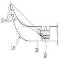
이하, 도 11을 참조하여, 본 발명의 일 실시예에 따른 수술 기구의 작동을 구체적으로 설명한다.Hereinafter, with reference to Figure 11, the operation of the surgical instrument according to an embodiment of the present invention will be described in detail.
도 11은 본 발명에 따른 수술 기구의 사용 상태를 설명하기 위한 예시도이다.11 is an exemplary view for explaining a state of use of the surgical instrument according to the present invention.
도 11에 도시된 바와 같이, 수술자는 수술 기구의 손잡이부(113,123)에 손가락을 끼워 파지한 상태로 수술 기구를 신체 내부로 진입시키게 되는데, 수술 기구의 양 선단을 하향으로 한 상태로 생체 조직 사이를 파고 들면서 조직 간격을 벌리는 조직 박리를 시행하면서 수술자가 원하는 수술 부위로 진입을 하게 된다. 이때, 조직 박리 등을 시행하는 과정에서 생체 조직 사이에서 출혈이 발생하게 되는데, 본 발명에 따른 수술 기구의 제 1 몸체부(110)와 제 2 몸체부(120)에 내장된 튜브관(117,127)이 흡입부(600)와 연결되도록 스위칭 밸브(800)를 선택 조정하면 튜브관(117,127)과 연결된 각 선단의 구멍들(111,121)을 통해 수술 중 환자의 출혈 부 위에서 발생하는 혈액 및 이물질 등을 흡입하여 제거함으로써 수술 시야를 확보할 수 있다. 또한, 튜브관(117,127)이 유체공급부(700)와 연결되도록 스위칭 밸브(800)를 선택 조정하면 튜브관(117,127)과 연결된 구멍들(111,121)을 통해 물, 소독액, 약액 등을 배출시킴으로써 환자의 출혈 부위를 세척하거나 수술 부위에 약액을 주입할 수 있다.As shown in FIG. 11, the operator enters the surgical instrument into the body with the fingers held by the
또한, 수술자가 원하는 수술 부위로 진행을 위해 수술 기구를 더 깊이 진입시켜 조직 박리 수술 부위가 더 깊어지게 되면 수술자는 육안으로 더 이상 접근이 어렵기 때문에 수술 시야를 확보하는데 한계가 있다. 이때, 수술 기구의 힌지부(200)에 소형 카메라(300)를 내장하여 환자의 생체 조직 수술 시 카메라(300)가 수술 부위를 촬영하여 촬영된 영상정보를 모니터(미도시)로 출력해 준다. 따라서, 수술자는 카메라(300)와 연결된 모니터를 보면서 육안으로 접근이 어려운 심도가 깊은 수술 부위에 대해서도 수술 시야를 확보할 수 있게 됨으로써, 생체 조직 박리 등과 같은 수술을 진행하면서 손상시키지 말아야 할 주요 혈관이나 중요 장기를 피해가면서 박리를 진행할 수 있게 되어 수술 위험도를 낮출 수 있다. 이때, 수술 기구의 선단이 벌려지고 닫히는 회전 운동 시 가이드로드(510)는 피니언(520)과 한 쌍의 랙(531,532) 기어에 의해 제 1 몸체부(110)와 제 2 몸체부(120) 사이의 중앙에 항상 위치하게 된다. 따라서, 가이드로드(510)와 연결된 힌지부(200)에 내장된 카메라(300)의 초점은 제 1 몸체부(110)의 선단과 제 2 몸체부(120)의 선단 사이의 조직 박리의 중심부위를 항상 유지하게 된다.In addition, when the surgical instrument enters the surgical instrument more deeply to proceed to the desired surgical site, the tissue detachment surgical site becomes deeper, so that the operator has no access to the naked eye, so there is a limit in securing a surgical field of vision. In this case, a
또한, 힌지부(200)에 내장된 광섬유(401,402)를 이용하여 광원에서 발생하는 광을 전송하여 제 1 몸체부(110)와 제 2 몸체부(120)의 선단 사이의 수술 부위를 조명함으로써 수술 시야를 확보할 수 있게 된다.In addition, by transmitting the light generated from the light source using the optical fiber (401,402) built in the
또한, 본 발명은 기존 가위 형태의 수술 기구와 유사한 모양으로 제작되므로 수술자는 본 수술 기구의 사용 습득이 용이하다.In addition, the present invention is manufactured in a shape similar to the conventional surgical instruments of the scissors type, the operator is easy to learn the use of the surgical instruments.
이상 첨부된 도면을 참조하여 본 발명의 실시 예를 설명하였지만, 본 발명이 속하는 기술분야에서 통상의 지식을 가진 자는 본 발명이 그 기술적 사상이나 필수적인 특징을 변경하지 않고서 다른 구체적인 형태로 실시될 수 있다는 것을 이해할 수 있을 것이다. 그러므로 이상에서 기술한 실시 예들은 모든 면에서 예시적인 것이며 한정적이 아닌 것으로 이해해야만 한다. 본 발명의 범위는 상기 상세한 설명보다는 후술하는 특허청구범위에 의하여 나타내어지며, 특허청구범위의 의미 및 범위 그리고 그 균등 개념으로부터 도출되는 모든 변경 또는 변형된 형태가 본 발명의 범위에 포함되는 것으로 해석되어야 한다.Although embodiments of the present invention have been described above with reference to the accompanying drawings, those skilled in the art to which the present invention pertains may implement the present invention in other specific forms without changing the technical spirit or essential features thereof. I can understand that. Therefore, it should be understood that the embodiments described above are exemplary in all respects and not restrictive. The scope of the present invention is shown by the following claims rather than the above description, and all changes or modifications derived from the meaning and scope of the claims and their equivalents should be construed as being included in the scope of the present invention. do.
도 1은 본 발명의 일 실시예에 따른 수술 기구를 개략적으로 도시한 사시도.1 is a perspective view schematically showing a surgical instrument according to an embodiment of the present invention.
도 2는 수술 기구의 선단부가 닫힌 상태를 도시한 평면도.2 is a plan view showing a state in which the distal end of the surgical instrument is closed;
도 3은 수술 기구의 선단부가 벌려진 상태를 도시한 평면도.3 is a plan view showing a state where the distal end of the surgical instrument is opened.
도 4는 도 1에 나타낸 수술 기구의 분해 사시도.4 is an exploded perspective view of the surgical instrument shown in FIG. 1;
도 5는 도 4에 나타낸 제 1 몸체부의 Ⅴ-Ⅴ선에 따른 단면도.5 is a cross-sectional view taken along the line VV of the first body part shown in FIG. 4;
도 6은 도 1의 A부분을 확대 도시한 사시도.6 is an enlarged perspective view of portion A of FIG. 1;
도 7은 도 1의 B부분을 확대 도시한 사시도.7 is an enlarged perspective view of portion B of FIG. 1;
도 8은 도 1의 C부분을 확대 도시한 사시도.8 is an enlarged perspective view illustrating a portion C of FIG. 1.
도 9는 도 1의 D부분을 확대 도시한 사시도.9 is an enlarged perspective view illustrating a portion D of FIG. 1.
도 10은 수술 기구에 내장된 카메라의 초점 위치를 도시한 예시도.10 is an exemplary view showing a focal position of a camera embedded in a surgical instrument.
도 11은 본 발명에 따른 수술 기구의 사용 상태를 설명하기 위한 예시도.11 is an exemplary view for explaining a state of use of the surgical instrument according to the present invention.
< 도면의 주요 부분에 대한 부호의 설명 ><Description of Symbols for Main Parts of Drawings>
110 : 제 1 몸체부 115,125 : 힌지수용부110: first body portion 115,125: hinge receiving portion
117,127 : 튜브관 120 : 제 2 몸체부117,127: tube tube 120: second body portion
200 : 힌지부 210 : 힌지몸체200: hinge portion 210: hinge body
300 : 촬영부,카메라 400 : 조명부300: photographing unit, camera 400: lighting unit
401,402 : 광섬유 500 : 카메라 가이드부401,402: fiber 500: camera guide
510 : 가이드로드 520 : 피니언(pinion)510: guide rod 520: pinion
531,532 : 랙(rack) 600 : 흡입부531,532
700 : 유체공급부 800 : 스위칭 밸브700: fluid supply part 800: switching valve
Claims (20)
Translated fromKoreanPriority Applications (4)
| Application Number | Priority Date | Filing Date | Title |
|---|---|---|---|
| KR1020090039091AKR101070049B1 (en) | 2009-05-06 | 2009-05-06 | Surgical instrument |
| EP09010619AEP2248472B1 (en) | 2009-05-06 | 2009-08-18 | Surgical instrument |
| US12/583,734US8377049B2 (en) | 2009-05-06 | 2009-08-24 | Surgical instrument |
| JP2009217212AJP4990336B2 (en) | 2009-05-06 | 2009-09-18 | Surgical instruments |
Applications Claiming Priority (1)
| Application Number | Priority Date | Filing Date | Title |
|---|---|---|---|
| KR1020090039091AKR101070049B1 (en) | 2009-05-06 | 2009-05-06 | Surgical instrument |
Publications (2)
| Publication Number | Publication Date |
|---|---|
| KR20100120330A KR20100120330A (en) | 2010-11-16 |
| KR101070049B1true KR101070049B1 (en) | 2011-10-04 |
Family
ID=42244839
Family Applications (1)
| Application Number | Title | Priority Date | Filing Date |
|---|---|---|---|
| KR1020090039091AExpired - Fee RelatedKR101070049B1 (en) | 2009-05-06 | 2009-05-06 | Surgical instrument |
Country Status (4)
| Country | Link |
|---|---|
| US (1) | US8377049B2 (en) |
| EP (1) | EP2248472B1 (en) |
| JP (1) | JP4990336B2 (en) |
| KR (1) | KR101070049B1 (en) |
Cited By (2)
| Publication number | Priority date | Publication date | Assignee | Title |
|---|---|---|---|---|
| WO2019132443A1 (en)* | 2017-12-29 | 2019-07-04 | (의료)길의료재단 | Ultrasonic cutter for sucking high-temperature spray |
| WO2020130415A1 (en)* | 2018-12-17 | 2020-06-25 | 의료법인 명지의료재단 | Multifunctional surgical dissector |
Families Citing this family (13)
| Publication number | Priority date | Publication date | Assignee | Title |
|---|---|---|---|---|
| KR101096401B1 (en)* | 2009-04-27 | 2011-12-21 | 국립암센터 | Surgical instruments |
| RU2705046C2 (en) | 2013-04-01 | 2019-11-01 | Винод В. ПАТХИ | Lighting device |
| USD938095S1 (en) | 2013-04-01 | 2021-12-07 | Pathy Medical, Llc | Lighting device |
| CN103750945A (en)* | 2014-01-14 | 2014-04-30 | 宋兹洋 | Ophthalmologic operation skin preparing device |
| TWI511071B (en)* | 2014-08-06 | 2015-12-01 | Kera Harvest Inc | Surgical planning system |
| CN105434042B (en)* | 2014-08-25 | 2017-08-25 | 成果科技股份有限公司 | Operation planning system |
| US9681767B1 (en)* | 2015-12-03 | 2017-06-20 | Loren Charles Barker | Compression stocking donning aid |
| CN106725727A (en)* | 2016-12-17 | 2017-05-31 | 黄萍 | A kind of medical surgical forceps |
| US11871919B2 (en) | 2017-03-29 | 2024-01-16 | Maureen Darwal | Transnasal odontoid retractor |
| KR20200142227A (en)* | 2019-06-12 | 2020-12-22 | 가톨릭대학교 산학협력단 | Apparatus for ophthalmic surgery capable of self-lighting |
| CN110215244B (en)* | 2019-07-18 | 2021-02-05 | 拾欣 | A strut mechanism for orthopedics backbone operation tissue |
| CN111904544B (en)* | 2020-09-09 | 2021-10-15 | 深圳市前海极智创新科技有限公司 | Cardiovascular surgery is with bronchus pincers |
| JP2022079009A (en)* | 2020-11-14 | 2022-05-26 | 順治 今西 | Laparoscopic surgery cleaning device |
Citations (2)
| Publication number | Priority date | Publication date | Assignee | Title |
|---|---|---|---|---|
| JP2002000614A (en)* | 2000-06-19 | 2002-01-08 | Olympus Optical Co Ltd | Operating instrument |
| JP2005028001A (en) | 2003-07-10 | 2005-02-03 | Showa Ika Kohgyo Co Ltd | Retractor |
Family Cites Families (27)
| Publication number | Priority date | Publication date | Assignee | Title |
|---|---|---|---|---|
| US390561A (en)* | 1888-10-02 | Dental mouth-opening forceps | ||
| US848126A (en)* | 1906-07-27 | 1907-03-26 | Giles F Roosevelt | Anastomotic clamp. |
| US2333740A (en)* | 1943-05-11 | 1943-11-09 | Edward L Rasmussen | Removable blade shears |
| US3980086A (en)* | 1974-02-28 | 1976-09-14 | Bio-Medicus, Inc. | Fluid conveying surgical instrument |
| US3916910A (en)* | 1974-06-10 | 1975-11-04 | Philip Seeling | Surgical instrument for plastic surgery |
| US5147356A (en)* | 1991-04-16 | 1992-09-15 | Microsurge, Inc. | Surgical instrument |
| US5336221A (en)* | 1992-10-14 | 1994-08-09 | Premier Laser Systems, Inc. | Method and apparatus for applying thermal energy to tissue using a clamp |
| CA2144211C (en)* | 1994-03-16 | 2005-05-24 | David T. Green | Surgical instruments useful for endoscopic spinal procedures |
| US6185356B1 (en)* | 1995-06-27 | 2001-02-06 | Lumitex, Inc. | Protective cover for a lighting device |
| US5727569A (en)* | 1996-02-20 | 1998-03-17 | Cardiothoracic Systems, Inc. | Surgical devices for imposing a negative pressure to fix the position of cardiac tissue during surgery |
| US5891017A (en)* | 1997-01-31 | 1999-04-06 | Baxter Research Medical, Inc. | Surgical stabilizer and method for isolating and immobilizing cardiac tissue |
| US20050171408A1 (en)* | 1997-07-02 | 2005-08-04 | Parker Jeffery R. | Light delivery systems and applications thereof |
| US6582451B1 (en)* | 1999-03-16 | 2003-06-24 | The University Of Sydney | Device for use in surgery |
| EP1208331A4 (en)* | 1999-07-20 | 2005-01-05 | Mickey M Karram | Surgical illumination device and method of use |
| GB0120410D0 (en)* | 2001-08-23 | 2001-10-17 | Hussien Maged | Retractor apparatus |
| KR200338068Y1 (en) | 2003-10-16 | 2004-01-13 | 박성진 | dissector for a surgical operation |
| JP4229443B2 (en)* | 2004-01-23 | 2009-02-25 | スタンレー電気株式会社 | Medical device with lighting device |
| DE102004015642B3 (en)* | 2004-03-31 | 2006-02-02 | Siemens Ag | Device for elimination of complete occlusion with OCT monitoring |
| US20050272977A1 (en)* | 2004-04-14 | 2005-12-08 | Usgi Medical Inc. | Methods and apparatus for performing endoluminal procedures |
| KR100592944B1 (en) | 2005-03-22 | 2006-06-26 | 문현준 | Multiple annular tubular separator |
| US8517933B2 (en)* | 2006-06-13 | 2013-08-27 | Intuitive Surgical Operations, Inc. | Retraction of tissue for single port entry, robotically assisted medical procedures |
| US20080097519A1 (en)* | 2006-10-20 | 2008-04-24 | Alfred E. Mann Foundation For Scientific Research | Medical device extraction tool |
| KR100828135B1 (en) | 2006-12-13 | 2008-05-08 | 이은규 | Biotissue exfoliator for endoscope |
| US8753365B2 (en)* | 2007-07-05 | 2014-06-17 | Rabin Gerrah | Device for harvesting a blood vessel |
| KR100910589B1 (en) | 2007-10-17 | 2009-08-03 | 충남대학교산학협력단 | Clothes pressure measurement method using cloth simulator |
| KR101096401B1 (en)* | 2009-04-27 | 2011-12-21 | 국립암센터 | Surgical instruments |
| KR101814830B1 (en)* | 2009-09-16 | 2018-01-04 | 메디거스 엘티디. | Small diameter video camera heads and visualization probes and medical devices containing them |
- 2009
- 2009-05-06KRKR1020090039091Apatent/KR101070049B1/ennot_activeExpired - Fee Related
- 2009-08-18EPEP09010619Apatent/EP2248472B1/ennot_activeNot-in-force
- 2009-08-24USUS12/583,734patent/US8377049B2/ennot_activeExpired - Fee Related
- 2009-09-18JPJP2009217212Apatent/JP4990336B2/ennot_activeExpired - Fee Related
Patent Citations (2)
| Publication number | Priority date | Publication date | Assignee | Title |
|---|---|---|---|---|
| JP2002000614A (en)* | 2000-06-19 | 2002-01-08 | Olympus Optical Co Ltd | Operating instrument |
| JP2005028001A (en) | 2003-07-10 | 2005-02-03 | Showa Ika Kohgyo Co Ltd | Retractor |
Cited By (2)
| Publication number | Priority date | Publication date | Assignee | Title |
|---|---|---|---|---|
| WO2019132443A1 (en)* | 2017-12-29 | 2019-07-04 | (의료)길의료재단 | Ultrasonic cutter for sucking high-temperature spray |
| WO2020130415A1 (en)* | 2018-12-17 | 2020-06-25 | 의료법인 명지의료재단 | Multifunctional surgical dissector |
Also Published As
| Publication number | Publication date |
|---|---|
| JP2010259770A (en) | 2010-11-18 |
| EP2248472B1 (en) | 2012-12-26 |
| EP2248472A1 (en) | 2010-11-10 |
| JP4990336B2 (en) | 2012-08-01 |
| US8377049B2 (en) | 2013-02-19 |
| US20100286675A1 (en) | 2010-11-11 |
| KR20100120330A (en) | 2010-11-16 |
Similar Documents
| Publication | Publication Date | Title |
|---|---|---|
| KR101070049B1 (en) | Surgical instrument | |
| KR101096401B1 (en) | Surgical instruments | |
| EP1955643B1 (en) | Guiding long medical member and long medical device | |
| JP4833200B2 (en) | Medical instruments | |
| US20190150902A1 (en) | Invasive instrument for treating vessels | |
| JP5431270B2 (en) | Endoscope tip cover and endoscope | |
| CN1411357A (en) | Pivotal and illuminated saphenous vein retractor | |
| CN110215180B (en) | Rigid endoscope device | |
| US20190350605A1 (en) | Suction forceps for endoscopic surgery | |
| TWI726309B (en) | Endocranial endoscope and method for using endocranial endoscope | |
| CN114847840A (en) | Endoscope set and endoscope system with working instruments | |
| CN107529955A (en) | Endoscopic system | |
| JP3806516B2 (en) | Endoscope system | |
| KR101881226B1 (en) | Catheter Assembly for Endoscope | |
| JP2016158804A (en) | Pericardium puncture device | |
| CN215994148U (en) | Visual needle knife and medical equipment | |
| KR20190124575A (en) | Biological tissue dissection device with endoscope | |
| KR101592208B1 (en) | Ultraviolet treatment kit | |
| JP3369641B2 (en) | Rigid endoscope | |
| JP6846759B2 (en) | Laser chips, laser treatment tools, laser treatment equipment, and laser treatment systems | |
| KR20100000280A (en) | Surgical instrument | |
| CN219743471U (en) | Visual suction tube for minimally invasive surgery | |
| JP7209976B2 (en) | Irradiation equipment for endoscopic surgery | |
| CZ20001618A3 (en) | Videorektoskop |
Legal Events
| Date | Code | Title | Description |
|---|---|---|---|
| A201 | Request for examination | ||
| PA0109 | Patent application | St.27 status event code:A-0-1-A10-A12-nap-PA0109 | |
| PA0201 | Request for examination | St.27 status event code:A-1-2-D10-D11-exm-PA0201 | |
| R18-X000 | Changes to party contact information recorded | St.27 status event code:A-3-3-R10-R18-oth-X000 | |
| D13-X000 | Search requested | St.27 status event code:A-1-2-D10-D13-srh-X000 | |
| D14-X000 | Search report completed | St.27 status event code:A-1-2-D10-D14-srh-X000 | |
| PG1501 | Laying open of application | St.27 status event code:A-1-1-Q10-Q12-nap-PG1501 | |
| E902 | Notification of reason for refusal | ||
| PE0902 | Notice of grounds for rejection | St.27 status event code:A-1-2-D10-D21-exm-PE0902 | |
| E13-X000 | Pre-grant limitation requested | St.27 status event code:A-2-3-E10-E13-lim-X000 | |
| P11-X000 | Amendment of application requested | St.27 status event code:A-2-2-P10-P11-nap-X000 | |
| P13-X000 | Application amended | St.27 status event code:A-2-2-P10-P13-nap-X000 | |
| E701 | Decision to grant or registration of patent right | ||
| PE0701 | Decision of registration | St.27 status event code:A-1-2-D10-D22-exm-PE0701 | |
| GRNT | Written decision to grant | ||
| PR0701 | Registration of establishment | St.27 status event code:A-2-4-F10-F11-exm-PR0701 | |
| PR1002 | Payment of registration fee | St.27 status event code:A-2-2-U10-U11-oth-PR1002 Fee payment year number:1 | |
| PG1601 | Publication of registration | St.27 status event code:A-4-4-Q10-Q13-nap-PG1601 | |
| FPAY | Annual fee payment | Payment date:20140918 Year of fee payment:4 | |
| PR1001 | Payment of annual fee | St.27 status event code:A-4-4-U10-U11-oth-PR1001 Fee payment year number:4 | |
| FPAY | Annual fee payment | Payment date:20150921 Year of fee payment:5 | |
| PR1001 | Payment of annual fee | St.27 status event code:A-4-4-U10-U11-oth-PR1001 Fee payment year number:5 | |
| FPAY | Annual fee payment | Payment date:20160920 Year of fee payment:6 | |
| PR1001 | Payment of annual fee | St.27 status event code:A-4-4-U10-U11-oth-PR1001 Fee payment year number:6 | |
| FPAY | Annual fee payment | Payment date:20170926 Year of fee payment:7 | |
| PR1001 | Payment of annual fee | St.27 status event code:A-4-4-U10-U11-oth-PR1001 Fee payment year number:7 | |
| FPAY | Annual fee payment | Payment date:20180919 Year of fee payment:8 | |
| PR1001 | Payment of annual fee | St.27 status event code:A-4-4-U10-U11-oth-PR1001 Fee payment year number:8 | |
| PC1903 | Unpaid annual fee | St.27 status event code:A-4-4-U10-U13-oth-PC1903 Not in force date:20190928 Payment event data comment text:Termination Category : DEFAULT_OF_REGISTRATION_FEE | |
| PC1903 | Unpaid annual fee | St.27 status event code:N-4-6-H10-H13-oth-PC1903 Ip right cessation event data comment text:Termination Category : DEFAULT_OF_REGISTRATION_FEE Not in force date:20190928 |