KR101067831B1 - Leakage coaxial antenna - Google Patents
Leakage coaxial antennaDownload PDFInfo
- Publication number
- KR101067831B1 KR101067831B1KR1020087019052AKR20087019052AKR101067831B1KR 101067831 B1KR101067831 B1KR 101067831B1KR 1020087019052 AKR1020087019052 AKR 1020087019052AKR 20087019052 AKR20087019052 AKR 20087019052AKR 101067831 B1KR101067831 B1KR 101067831B1
- Authority
- KR
- South Korea
- Prior art keywords
- antenna
- shield conductor
- conductor
- shield
- openings
- Prior art date
- Legal status (The legal status is an assumption and is not a legal conclusion. Google has not performed a legal analysis and makes no representation as to the accuracy of the status listed.)
- Expired - Fee Related
Links
Images


Classifications
- H—ELECTRICITY
- H04—ELECTRIC COMMUNICATION TECHNIQUE
- H04B—TRANSMISSION
- H04B5/00—Near-field transmission systems, e.g. inductive or capacitive transmission systems
- H04B5/20—Near-field transmission systems, e.g. inductive or capacitive transmission systems characterised by the transmission technique; characterised by the transmission medium
- H04B5/28—Near-field transmission systems, e.g. inductive or capacitive transmission systems characterised by the transmission technique; characterised by the transmission medium using the near field of leaky cables, e.g. of leaky coaxial cables
- H—ELECTRICITY
- H01—ELECTRIC ELEMENTS
- H01Q—ANTENNAS, i.e. RADIO AERIALS
- H01Q1/00—Details of, or arrangements associated with, antennas
- H01Q1/08—Means for collapsing antennas or parts thereof
- H01Q1/085—Flexible aerials; Whip aerials with a resilient base
- H—ELECTRICITY
- H01—ELECTRIC ELEMENTS
- H01Q—ANTENNAS, i.e. RADIO AERIALS
- H01Q1/00—Details of, or arrangements associated with, antennas
- H01Q1/27—Adaptation for use in or on movable bodies
- H01Q1/28—Adaptation for use in or on aircraft, missiles, satellites, or balloons
- H01Q1/285—Aircraft wire antennas
- H—ELECTRICITY
- H01—ELECTRIC ELEMENTS
- H01Q—ANTENNAS, i.e. RADIO AERIALS
- H01Q13/00—Waveguide horns or mouths; Slot antennas; Leaky-waveguide antennas; Equivalent structures causing radiation along the transmission path of a guided wave
- H01Q13/20—Non-resonant leaky-waveguide or transmission-line antennas; Equivalent structures causing radiation along the transmission path of a guided wave
- H01Q13/203—Leaky coaxial lines
Landscapes
- Engineering & Computer Science (AREA)
- Aviation & Aerospace Engineering (AREA)
- Remote Sensing (AREA)
- Physics & Mathematics (AREA)
- Astronomy & Astrophysics (AREA)
- General Physics & Mathematics (AREA)
- Computer Networks & Wireless Communication (AREA)
- Signal Processing (AREA)
- Waveguide Aerials (AREA)
- Waveguides (AREA)
- Details Of Aerials (AREA)
Abstract
Translated fromKoreanDescription
Translated fromKorean본 발명은 내부 도전체, 상기 내부 도전체 주위의 유전체, 및 상기 유전체 주위에 배치된 실드 도전체(shield conductor)를 포함하는 누설 동축 안테나에 관한 것으로, 상기 실드 도전체는 상기 내부 도전체의 길이 방향(longitudinal direction)으로 분포된 개구부들을 가지며, 전자기 에너지가 상기 개구부들을 통과하도록 되어 있다. 특히, 이러한 누설 동축 안테나는 비행기들이나 다른 어플리케이션들에 사용될 수 있다.The present invention relates to a leaky coaxial antenna comprising an inner conductor, a dielectric around the inner conductor, and a shield conductor disposed around the dielectric, wherein the shield conductor is the length of the inner conductor. It has openings distributed in a longitudinal direction, and electromagnetic energy is adapted to pass through the openings. In particular, such leaky coaxial antennas can be used in airplanes or other applications.
누설 및/또는 방사(radiating) 동축 케이블들은 터널, 광산, 빌딩과 같은 한정된 공간들에서, 및/또는 (철도 및 도로와 같은) 좁은 가로방향 복도(lateral corridor)를 수반하는 다른 확대된(stretched-out) 어플리케이션들에서 길이 방향 안테나들로서 채택될 수 있다. 오늘날의 어플리케이션들에서, 이러한 케이블들은 비행기와 같은 확대된 자동차에서 채택될 수 있으며, 일-방향 또는 쌍-방향 통신이 요구된다. 누설 동축 케이블들은 표면파들을 지원하며, 전력의 일부분이 반경 방향으로 방사된다. 누설 동축 케이블들은 방사 또는 커플링 모드에서 작동한다. 이들 모드들은 모든 기여 어퍼처(contributing aperture)들의 동위상(in-phase) 추가에 대응한다.Leaking and / or radiating coaxial cables are in confined spaces such as tunnels, mines, buildings, and / or other stretched- enclosed narrow narrow corridors (such as railways and roads). out) may be employed as longitudinal antennas in applications. In today's applications, these cables can be employed in expanded automobiles such as airplanes and require one-way or two-way communication. Leakage coaxial cables support surface waves and a fraction of the power is radiated radially. Leakage coaxial cables operate in radial or coupling mode. These modes correspond to the in-phase addition of all contributing apertures.
공지된 대부분의 누설 및/또는 방사 동축 케이블들은 무겁고, 직경이 크며, 유연성이 없다. 하지만, 상기에 언급된 몇몇 어플리케이션과 같이 사용되는 어플리케이션들은 가볍거나 유연한 케이블들을 필요로 하지 않기 때문에, 이는 지금까지 문제가 되지 않았다. 하지만, 예를 들어 특히 비행기에서의 사용에 대해서는 이러한 단점들이 유익하지 않을 수 있다.Most known leaky and / or radial coaxial cables are heavy, large in diameter and inflexible. However, this has not been a problem until now because applications used with some of the above mentioned applications do not require light or flexible cables. However, these disadvantages may not be beneficial, for example, especially for use on an airplane.
US 4 599 121호는 브레이딩(braiding: 땋음, 꼼)이 제조 공정에서 행해짐에 따라 실드 와이어(shield wire)의 단부들을 강하(drop)시킴으로써 그 안에 생성된 개구부를 갖는 연속적으로 브레이드된 실드(braided shield)를 이용함으로써 누설 동축 케이블을 생성하는 방법에 관한 것이다.US 4 599 121 discloses a continuously braided shield having an opening created therein by dropping the ends of the shield wire as braiding is done in the manufacturing process. to create a leaky coaxial cable.
US 5 936 203 A호는 연속한 다수의 도전성 스트립(strip)들에 의해 형성된 외부 도전체를 갖는 방사 동축 케이블에 관한 것이다. 복수의 도전성 스트립들은 중심 도전체에 대해 동축으로 연속적으로 감겨 있으며, 유전 코어에 의해 분리된다. 복수의 도전성 스트립들은 조합하여 방사 케이블의 또 다른 도전체를 정의하고, 상기 케이블의 여기(excitation)에 반응하여 전자기 에너지를 방사하고 수용하도록 도전성 스트립들 사이에 복수의 갭들 또는 어퍼처들을 정의한다.US 5 936 203 A relates to a radial coaxial cable having an outer conductor formed by a plurality of consecutive conductive strips. The plurality of conductive strips are continuously wound coaxially with respect to the center conductor and are separated by the dielectric core. The plurality of conductive strips in combination define another conductor of the radiating cable and defines a plurality of gaps or apertures between the conductive strips to radiate and receive electromagnetic energy in response to the excitation of the cable.
US 4 339 733호는 1 이상의 중심 도전체, 상기 중심 도전체를 둘러싸는 유전 코어, 및 상기 유전 코어의 길이를 따라 상기 중심 도전체에 대해 동축으로 배치된 복수의 방사 외장(radiating sheath)을 포함하는 방사 케이블에 관한 것이다. 특히, 상기 외장은 브레이드와 같은 연속한 구조체들, 나선형으로 또는 길이 방향으로 감싸진 구조체들에 의해 수행된다.US 4 339 733 includes at least one center conductor, a dielectric core surrounding the center conductor, and a plurality of radiating sheaths disposed coaxially with respect to the center conductor along the length of the dielectric core. It relates to a radiation cable. In particular, the sheathing is carried out by continuous structures such as braids, spirally or longitudinally wrapped structures.
DE 26 36 523 A1은 절연 코팅으로 덮인 방사 동축 전달(radiating coaxial transmission)에 관한 것이다. 유사한 원통형 방사 요소들은 라인 상에서, 그리고 상기 라인 내에 또한 상기 라인을 통해 전달된 고 주파수 대역의 중심 주파수의 파장과 같은 중심-대-중심 거리에서 등거리에 위치된다. 상기 절연 코팅은 환경에 대해 외부 도전체를 절연시키고, 반경 요소들에 대해 지지면을 생성한다. 바람직하게, 각각의 방사기(radiator)는 방사될 투과 대역의 중심 주파수 파장의 절반인 길이를 갖는다.DE 26 36 523 A1 relates to radiating coaxial transmission covered by an insulating coating. Similar cylindrical radiating elements are equidistantly located on the line and at the center-to-center distance, such as the wavelength of the center frequency of the high frequency band transmitted in and through the line. The insulating coating insulates the outer conductor with respect to the environment and creates a support surface for the radial elements. Preferably, each radiator has a length that is half of the center frequency wavelength of the transmission band to be emitted.
상기의 참조문헌들 중 몇몇에서 구현된 공지된 누설 및/또는 방사 동축 케이블들 중 어느 것도 항공 우주 공학(aerospace) 어플리케이션들에서 사용하기 위한 모든 요건들을 충족하지 않는다. 개방형 브레이드 구조를 사용하는 유연한 설계들은 제한된 대역폭과 높은 길이 방향 손실들을 갖지만, 개구부들을 구비한 상승된(ridged) 외부 도전체를 갖는 설계들은 큰 굴곡 반경(bend radius)을 가지며, 유연성이 부족하다. 특히, 비행기에서 WLAN 및 GSM과 같은 무선 어플리케이션용 분배 안테나(distributed antenna)로서 사용하기 위한 누설/방사 동축 케이블은 다수의 특정 요건들을 충족하여야만 한다. 이들 요건들은 (1 Ohm 미만의 임피던스 변화를 갖는 32 mm의 굴곡 반경을 갖는) 유연성, 높은 대역폭 및 광대역(400 ㎒ 내지 6 ㎓), 경량의 무게(190 g/m), 그리고, 예를 들어 최대 60 m의 안테나 길이에서 주파수 대역 내의 동작을 지원하도록 낮은 길이 방향 손실(6 ㎓에서 0.36 dB/m 미만의 감쇠)을 가질 것을 포함한다. 비행기에서 사용하기 위한 누설/방사 동축 케이블은 다수의 다른 장애물들로 인해 안테나가 직선이 될 수 없는 비행기의 내부에 설치될 것이기 때문에 유연성이 있어야 한다. 상기 누설/방사 동축 케이블은 다수의 무선 통신 표준들이 수 ㎓에서 동작하기 때문에 높은 주파수 응답을 가져야 한다. 상기 누설/방사 동축 케이블은 각각의 무선 통신 표준들이 하나의 안테나 내에서 그 자체의 주파수 대역에서 동작하기 때문에 높은 대역폭을 가져야 한다. 상기 누설/방사 동축 케이블은 비행기 무게를 최소화하고자 하는 비행기 사양들에 따르기 위해 가벼워야 한다. 상기 누설/방사 동축 케이블은 수신 및/또는 송신 안테나로서 기능하도록 충분한 방사 손실을 갖는 한편 충분한 도달 길이(reach length)를 허용하도록 낮은 길이 방향 손실을 가져야 한다. 마지막으로, 상기 방사 손실은 상기 길이를 따라 균질(homogenous)해야 하며, 단면의 외주 방사 패턴이 어플리케이션, 예를 들어 비행기 사양에 의해 정의된 특정화된 잡음 면역 요건들을 유지하게 하여야 한다.None of the known leakage and / or radiant coaxial cables implemented in some of the above references meet all requirements for use in aerospace applications. Flexible designs using an open braid structure have limited bandwidth and high longitudinal losses, but designs with ridged external conductors with openings have large bend radius and lack flexibility. In particular, leakage / radiation coaxial cable for use as a distributed antenna for wireless applications such as WLAN and GSM in an airplane must meet a number of specific requirements. These requirements include flexibility (with 32 mm bend radius with less than 1 Ohm impedance change), high bandwidth and broadband (400 MHz to 6 Hz), light weight (190 g / m), and, for example, maximum It has low longitudinal loss (attenuation less than 0.36 dB / m at 6 kHz) to support operation in the frequency band at an antenna length of 60 m. Leakage / radiation coaxial cables for use in airplanes must be flexible because they will be installed inside the airplane where the antenna cannot be straight due to many other obstacles. The leakage / radiation coaxial cable must have a high frequency response because many wireless communication standards operate at several kilohertz. The leakage / radiation coaxial cable must have a high bandwidth because each wireless communication standard operates in its own frequency band within one antenna. The leakage / radiation coaxial cable should be light in order to comply with airplane specifications to minimize airplane weight. The leakage / radiation coaxial cable should have sufficient radiation loss to function as a receiving and / or transmitting antenna while having a low longitudinal loss to allow sufficient reach length. Finally, the radiation loss must be homogenous along the length, and the outer radiation pattern of the cross section must maintain the specified noise immunity requirements defined by the application, eg airplane specification.
그러므로, 본 발명의 목적은 기존의 해결책들의 상기 언급된 단점들 중 적어도 몇몇을 개선할 수 있는 누설 동축 안테나를 제공하는 것이다.It is therefore an object of the present invention to provide a leaky coaxial antenna which can remedy at least some of the above mentioned disadvantages of existing solutions.
상기 목적은 청구항 제 1 항 또는 제 2 항의 특징들에 따른 누설 동축 안테나에 의해 해결된다. 본 발명에 따른 누설 동축 안테나의 실시예들은 종속항들로부터 분명히 알 수 있다.This object is solved by a leaky coaxial antenna according to the features of
특히, 본 발명의 제 1 실시형태에 따르면, 누설 동축 안테나는 내부 도전체, 상기 내부 도전체 주위의 유전체, 및 상기 유전체 주위에 배치된 제 1 실드 도전체를 포함하고, 상기 제 1 실드 도전체는 상기 내부 도전체의 길이 방향으로 분포된 개구부들을 가지며, 전자기 에너지가 상기 개구부들을 통과하도록 되어 있다. 제 2 실드 도전체는 상기 제 1 실드 도전체 주위에 배치되며, 상기 제 2 실드 도전체는 실드된 구간에서 상기 제 1 실드 도전체의 상기 개구부들 중 1 이상을 덮어, 상기 전자기 에너지가 상기 실드된 구간 내에서 상기 안테나의 외부로 방출되는 것을 방지하도록 되어 있다. 또한, 상기 제 2 실드 도전체는 상기 안테나의 길이 방향으로 상기 제 1 실드 도전체의 덮이지 않은 부분들을 정의하도록 상기 안테나의 길이 방향으로 불연속적으로(discontinuously) 배치되며, 이들은 전자기 에너지가 덮이지 않은 부분들을 통과하도록 되어 있다.In particular, according to a first embodiment of the present invention, a leaky coaxial antenna includes an inner conductor, a dielectric around the inner conductor, and a first shield conductor disposed around the dielectric, wherein the first shield conductor Has openings distributed in the longitudinal direction of the inner conductor, and electromagnetic energy is adapted to pass through the openings. A second shield conductor is disposed around the first shield conductor, and the second shield conductor covers at least one of the openings of the first shield conductor in a shielded section, so that the electromagnetic energy is shielded. It is to prevent the emission to the outside of the antenna within the interval. Further, the second shield conductor is disposed discontinuously in the longitudinal direction of the antenna to define uncovered portions of the first shield conductor in the longitudinal direction of the antenna, which are not covered by electromagnetic energy. It is supposed to go through the parts that are not.
본 발명의 또 다른 실시형태에 따르면, 제 2 실드 도전체는 제 1 실드 도전체 밑에 배치되고, 상기 제 2 실드 도전체는 실드된 구간에서 상기 제 1 실드 도전체의 상기 다수의 개구부들을 전체 또는 부분적으로 차단하여, 전자기 에너지가 상기 실드된 구간 내에서 안테나의 외부로 방출되는 것을 방지하도록 되어 있다. 또한, 상기 제 2 실드 도전체는 상기 안테나의 길이 방향으로 상기 제 1 실드 도전체의 차단되지 않은 부분들을 정의하도록 상기 안테나의 길이 방향으로 불연속적으로 배치되며, 이들은 전자기 에너지가 차단되지 않은 구간들을 통해 나가도록 되어 있다.According to yet another embodiment of the present invention, a second shield conductor is disposed under the first shield conductor, and the second shield conductor is entirely or partially through the plurality of openings of the first shield conductor in the shielded section. By partially blocking, the electromagnetic energy is prevented from being emitted to the outside of the antenna within the shielded section. In addition, the second shield conductor is discontinuously disposed in the longitudinal direction of the antenna to define unblocked portions of the first shield conductor in the longitudinal direction of the antenna, and these sections are provided for sections in which electromagnetic energy is not blocked. It is supposed to go out.
따라서, 본 발명은 본 명세서의 도입부에 언급된 바와 같이, 누설 동축 안테나의 특성들을 개선시키기 위해 제 1 실드 도전체 및 제 2 실드 도전체를 포함하는 2-층 실드를 제안한다. 특히, 두 실드 층들은 케이블 벤딩(cable bending)을 허용하면서도, 제 2 실드 도전체를 포함하는 제 2 실드 층이 케이블 길이의 상당한 부분들에 걸쳐 제 1 실드 도전체를 포함하는 제 1 실드 층의 개구부들을 덮거나 차단하기 때문에, 동축 전달 모드의 길이 방향 손실이 현저히 감소될 수 있다. 이는 낮은 길이 방향 손실을 갖는 유연한 설계의 조합을 허용한다. 횡축 손실(transversal loss) 또는 방사의 양, 또한 누설 동축 케이블의 대역폭 및 도달 길이는 상이한 속성들 - 제 1 실드 층의 최상부 상에서의 제 2 실드 층의 포괄도(coverage), 또는 제 1 실드 층 밑의 제 2 실드 층의 차단에 의해, 그리고 제 1 실드 층의 덮이지 않은 또는 차단되지 않은 부분들(제 2 실드 층의 개구부들)의 길이에 의해 제어될 수 있다. 또한, 제 1 실드 층의 개구부들(예를 들어, 폭 및/또는 개수)은 이에 따라 변동될 수 있다. 이는 다수의 어플리케이션들에 본 발명의 적용을 허용한다. 이는, 항공 우주 공학 어플리케이션들에서와 같이 유연성과 조합하여 높은 대역폭과 긴 도달 길이가 요구되는 때에 특별한 중요성을 갖는다.Accordingly, the present invention proposes a two-layer shield comprising a first shield conductor and a second shield conductor to improve the characteristics of a leaky coaxial antenna, as mentioned at the beginning of this specification. In particular, the two shield layers allow for cable bending, while the second shield layer comprising the second shield conductor includes the first shield layer over a substantial portion of the cable length. By covering or blocking the openings, the longitudinal loss of the coaxial transmission mode can be significantly reduced. This allows for a combination of flexible designs with low longitudinal losses. The amount of transversal loss or radiation, as well as the bandwidth and arrival length of the leaky coaxial cable, may vary in different properties—coverage of the second shield layer on top of the first shield layer, or under the first shield layer. By the blocking of the second shield layer and by the length of the uncovered or unblocked portions of the first shield layer (openings of the second shield layer). In addition, the openings (eg, width and / or number) of the first shield layer may vary accordingly. This allows the application of the invention to many applications. This is of particular importance when high bandwidth and long reach lengths are required in combination with flexibility, such as in aerospace engineering applications.
본 발명의 일 실시예에 따르면, 제 2 실드 도전체는 다수의 튜브형 구간들을 포함하고, 상기 다수의 튜브형 구간들은 상기 튜브형 구간들 사이에 제 1 실드 도전체의 덮이지 않은 또는 차단되지 않은 부분들 각각을 정의하도록 안테나의 길이 방향으로 불연속적으로 배치된다.According to one embodiment of the invention, the second shield conductor comprises a plurality of tubular sections, the plurality of tubular sections between the uncovered or unblocked portions of the first shield conductor between the tubular sections. Discontinuously arranged in the longitudinal direction of the antenna to define each.
본 발명의 또 다른 실시예에 따르면, 제 2 실드 도전체는 적어도 안테나가 작동할 때 실드된 구간 내에 또는 제 1 실드 도전체에 전기적으로 커플링되도록 배치된다. 따라서, 제 1 실드 도전체가 접지 전위에 연결될 때, 제 2 실드 도전체는 실드 기능을 수행하도록 접지 전위에 연결될 것이다. 일 실시예에 따르면, 제 1 실드 도전체 및 제 2 실드 도전체는 서로 갈바닉 콘택(galvanic contact)을 유지하며, 두 실드 도전체들은 서로 직접 연결된다. 한편, 제 1 실드 도전체는 용량성 커플링을 통해 제 1 실드 도전체에 제 2 실드 도전체를 커플링하도록 용량성 거동(capacitive behaviour)을 갖는 물질들을 통해 제 2 실드 도전체에 연결될 수 있다. 이러한 커플링은 특히 누설 동축 안테나의 동작 주파수들에 대해 배치된다. 이와 관련하여, 예를 들어 제 1 실드 도전체와 제 2 실드 도전체 사이에 배치된 유전 물질은 용량성 커플링 요소로서 역할할 수 있다.According to another embodiment of the invention, the second shield conductor is arranged to be electrically coupled to the first shield conductor or at least within the shielded section when the antenna is operating. Thus, when the first shield conductor is connected to ground potential, the second shield conductor will be connected to ground potential to perform the shield function. According to one embodiment, the first shield conductor and the second shield conductor maintain galvanic contact with each other, and the two shield conductors are directly connected to each other. Meanwhile, the first shield conductor may be connected to the second shield conductor through materials having a capacitive behavior to couple the second shield conductor to the first shield conductor through capacitive coupling. . This coupling is in particular arranged for the operating frequencies of the leaky coaxial antenna. In this regard, for example, the dielectric material disposed between the first shield conductor and the second shield conductor can serve as a capacitive coupling element.
본 발명의 또 다른 실시예에 따르면, 도전성 스트립은 유전체의 외주 구간을 따라 길이 방향으로 배치되어, 상기 개구부들의 실드된 세그먼트 및 상기 개구부들의 실드되지 않은 세그먼트를 형성하며, 전자기 에너지는 상기 개구부들의 상기 실드되지 않은 세그먼트에서 상기 개구부들을 통과한다. 이러한 도전성 스트립은, 예를 들어 누설 동축 안테나의 바람직한 방향 안으로 전자기 에너지를 모으는데 적용될 수 있다. 또한, 이러한 도전성 스트립은 안테나의 정해진 위치들에 전자기 에너지를 집중시키는데 사용될 수 있으며, 길이 방향 손실을 감소시킨다.According to another embodiment of the invention, the conductive strip is disposed longitudinally along the outer circumferential section of the dielectric to form a shielded segment of the openings and an unshielded segment of the openings, the electromagnetic energy of the openings of the openings. Pass through the openings in the unshielded segment. Such conductive strips can be applied, for example, to attract electromagnetic energy into the preferred direction of the leaky coaxial antenna. In addition, such conductive strips can be used to concentrate electromagnetic energy at defined locations of the antenna, reducing longitudinal loss.
본 발명의 또 다른 실시예에 따르면, 제 1 실드 도전체 및 제 2 실드 도전체는 도전성 스트립을 통해 전기적으로 커플링된다.According to another embodiment of the present invention, the first shield conductor and the second shield conductor are electrically coupled via a conductive strip.
제 1 실드 도전체는 층 밑의 전체 표면을 덮지 않는 와이어 도전체들의 개방형 구조를 포함할 수 있다. 또 다른 실시예에 따르면, 제 1 실드 도전체는 개방형 구조의 도전성 포일 메시(foil mesh)를 포함한다. 또한, 내부 도전체는 플라스틱 코어 주위에 감싸진 금속 도전체를 포함할 수 있다. 이러한 플라스틱 코어 또는 플라스틱 튜브는 바람직하게 FEP(fluoroethylene propylene)로 구성된다. 유전체는 바람직하게 폴리테트라플루오로에틸렌이며, 가장 바람직하게는 발포(expanded) 폴리테트라플루오로에틸렌이다. 바람직하게, 비-도전성 재킷은 제 1 실드 도전체와 제 2 실드 도전체 주위에 배치된다.The first shield conductor may include an open structure of wire conductors that does not cover the entire surface under the layer. According to yet another embodiment, the first shield conductor comprises an open foil conductive foil mesh. The inner conductor can also include a metal conductor wrapped around the plastic core. This plastic core or plastic tube is preferably composed of fluoroethylene propylene (FEP). The dielectric is preferably polytetrafluoroethylene, most preferably expanded polytetrafluoroethylene. Preferably, the non-conductive jacket is disposed around the first shield conductor and the second shield conductor.
특정 실시예에서, 본 발명의 누설 동축 안테나는 본 명세서에 설명된 바와 같은 본 발명의 원리들에 따라 수정된 EP 0 635 850 A1 및 US 5 500 488 A에 개시된 기본 동축 케이블(base coaxial cable)을 포함할 수 있다. 즉, 본 명세서에 설명된 기본 원리들은 이러한 케이블에 적용될 수 있다. 특히, 내부 도전체는 플라스틱 코어 주위에 배치될 수 있으며, 상기 내부 도전체는 겹쳐지고, 나선형으로 감싸진 전기 도전성 필름의 형태로 된 내부 층, 및 상기 내부 층과 전기 접촉하는 서브된 와이어(served wire)들의 형태로 된 외부 층을 갖는 2 개의 층들을 포함할 수 있다.In a particular embodiment, the leaky coaxial antenna of the present invention uses the base coaxial cable disclosed in EP 0 635 850 A1 and
본 발명의 일 실시예에 따르면, 안테나 기능을 수행하는 동축 안테나의 구간들을 형성하는 제 1 실드 도전체의 덮이지 않은 또는 차단되지 않은 부분들 각각은 안테나의 길이 방향으로 안테나의 길이를 따라 변하는 상기 부분들 간의 거리를 갖는다. 특히, 상기 거리는 주기적인 공진들을 회피하도록 안테나의 길이를 따라 무작위 방식으로 변동할 수 있다. 이러한 주기적인 공진들은, 만약 발생한다면, 누설 동축 안테나의 성능을 저하시킬 수 있다. 이와 관련하여, 무작위 방식으로 변화한다는 것은 제 1 실드 도전체의 덮이지 않은 또는 차단되지 않은 부분들 간의 거리의 변동가능한 비-설정 구조 또는 적절성(legality)을 의미한다.According to one embodiment of the invention, each of the uncovered or unblocked portions of the first shield conductor forming sections of the coaxial antenna performing the antenna function varies along the length of the antenna in the longitudinal direction of the antenna. Has the distance between the parts. In particular, the distance can vary in a random manner along the length of the antenna to avoid periodic resonances. These periodic resonances, if they occur, can degrade the performance of the leaky coaxial antenna. In this regard, varying in a random manner means a variable non-setting structure or legality of the distance between uncovered or unblocked portions of the first shield conductor.
본 발명의 또 다른 실시예에 따르면, 제 1 실드 도전체의 덮이지 않은 또는 차단되지 않은 부분들 각각은 안테나의 길이를 따라 변동하는 안테나의 길이 방향으로의 폭을 갖는다. 특히, 덮이지 않은 또는 차단되지 않은 부분들 각각은, 안테나의 길이를 따라 더 균일한 방사 전력 손실을 생성하기 위해 케이블이 송신 단부로부터 수신 단부로 가로질러짐에(traverse) 따라 더 넓은 폭을 가질 수 있다.According to another embodiment of the invention, each of the uncovered or unblocked portions of the first shield conductor has a width in the longitudinal direction of the antenna that varies along the length of the antenna. In particular, each of the uncovered or unblocked portions may have a wider width as the cable traverses from the transmitting end to the receiving end to produce more uniform radiated power loss along the length of the antenna. Can be.
본 발명의 또 다른 실시예에 따르면, 덮이지 않은 또는 차단되지 않은 부분들 각각의 폭들을 변동시키고, 상기 부분들 간의 거리를 변동시키는 것의 조합은 조합적인 효과로 균일한 손실을 생성하고, 성능을 저하시킬 수 있는 주기적인 공진들을 회피하도록 의도된다.According to another embodiment of the present invention, the combination of varying the widths of each of the uncovered or unblocked portions and varying the distance between the portions produces a uniform loss with a combinatorial effect and improves performance. It is intended to avoid periodic resonances that may degrade.
본 발명의 누설 동축 안테나의 다양한 구성요소들은 여하한의 적절한 순서로 배치될 수 있다. 예를 들어, 동축 안테나는 약 190 g/m 미만의 무게와(그러나, 궁극적인 어플리케이션에 따라, 무게는 중요하지(critical) 않을 수도 있음), 32 mm 미만의 굴곡 반경과, 400 ㎒ 내지 6 ㎓ 사이의 대역폭과, 6 ㎓의 주파수에서 미터당 0.36 dB 미만의 길이 방향 감쇠를 갖는다.The various components of the leaky coaxial antenna of the present invention may be arranged in any suitable order. For example, a coaxial antenna may weigh less than about 190 g / m (but depending on the ultimate application, weight may not be critical), bend radius less than 32 mm, and 400 MHz to 6 Hz And a longitudinal attenuation of less than 0.36 dB per meter at a frequency of 6 kHz.
본 발명의 또 다른 실시예들과 유익한 특징들은 종속항들로부터 분명히 알 수 있다.Further embodiments and advantageous features of the invention are apparent from the dependent claims.
본 발명은 첨부된 도면과 연계하여 행해진 본 발명의 실시예들의 다음의 설명을 참조함으로써 더 쉽게 이해될 것이다.The invention will be more readily understood by reference to the following description of embodiments of the invention made in conjunction with the accompanying drawings.
도 1은 본 발명의 일 실시예에 따른 예시적인 누설 동축 안테나의 측면도;1 is a side view of an exemplary leaky coaxial antenna in accordance with one embodiment of the present invention;
도 2는 본 발명의 일 실시예에 따라 배치된 다양한 각각의 구성요소들을 도시하는 본 발명의 일 실시예에 따른 예시적인 누설 동축 안테나의 측면도;2 is a side view of an exemplary leaky coaxial antenna in accordance with one embodiment of the present invention showing various respective components disposed in accordance with one embodiment of the present invention;
도 3은 도 2의 예시적인 누설 동축 안테나의 단면도;3 is a cross-sectional view of the exemplary leaky coaxial antenna of FIG. 2;
도 4는 본 발명의 또 다른 실시예에 따른 또 다른 예시적인 누설 동축 안테나 조립체의 측면도; 및4 is a side view of another exemplary leaky coaxial antenna assembly according to another embodiment of the present invention; And
도 5는 본 발명에 따른 누설 동축 안테나의 또 다른 실시예의 부분들을 나타낸다.5 shows portions of yet another embodiment of a leaky coaxial antenna according to the invention.
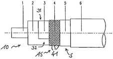
본 발명은 첨부된 도면들에 도시된 본 발명의 실시예들을 특히 참조하여 설명될 것이다. 도 1은 본 발명의 일 실시예에 따른 예시적인 누설 동축 안테나(10)의 측면도이다. 상기 동축 안테나(10)는 그 1 이상의 단부 상에서 커넥터(21: 도시되지 않음)에 커플링될 수 있다. 제 2 실드 도전체(5)는 상기 안테나의 길이 방향으로의 이산 위치(discrete position)들에서 불연속적으로 제 1 실드 도전체(4)의 덮이지 않은 부분들을 정의하도록 안테나(10)의 길이 방향으로 불연속적으로 배치된다.The invention will be described with particular reference to embodiments of the invention shown in the accompanying drawings. 1 is a side view of an exemplary leaky
본 발명에 따른 누설 동축 안테나의 더 세부적인 사항들은 도 2 및 도 3에 도시된다. 누설 동축 안테나(10)는 금속일 수 있거나, 이후 더 자세히 설명되는 바와 같이 플라스틱 튜브 주위에 감싸진 금속일 수 있는 내부 도전체(1)를 포함한다. 유전체(2)는 상기 내부 또는 중심 도전체(1) 주위에 배치되며, 상기 유전체는 여하한의 절연 물질일 수 있다. 예를 들어, 유전체(2)는 폴리테트라플루오로에틸렌(PTFE)이다. 특히, 유전체(2)는 발포 폴리테트라플루오로에틸렌(ePTFE)일 수 있다.More details of the leaky coaxial antenna according to the invention are shown in FIGS. 2 and 3. The leaky
일 실시예에 따르면, 누설 동축 안테나(10)는 실드된 세그먼트(31) 및 실드되지 않은 세그먼트(32)를 형성하도록 안테나의 길이 방향으로 유전체(2)의 외주 구간을 따라 배치된 도전성 스트립(3)을 가지며, 전자기 에너지는 상기 실드되지 않은 세그먼트(32)에서 안테나의 외부로 통과할 수 있다. 도전성 스트립(3)은 금속 또는 금속화된 포일(metallized foil) 또는 다른 도전성 층일 수 있다. 그 외부 표면의 일부분만을 덮는 동축 안테나(10)의 길이를 따른 도전성 스트립(3)을 배치함으로써, 도전성 스트립(3)으로부터 멀어지는 방향으로 실드되지 않은 세그먼트(32)로부터 전자기 에너지가 커플링하거나 방사한다. 이러한 방식으로, 전자기 에너지와 방사 패턴이 특정 방향들로 집중됨에 따라, 동축 안테나의 지향성(directivity)을 제어한다. 이는 근장(near field) 및/또는 원장(far field) 전자기장 밀도가 전자기 장애(electromagnetic interference: EMI)에 민감한 장비를 포함하는 영역들에서와 같이 민감한 영역들에서 제어되어야 하는 경우 특히 중요하다According to one embodiment, the leaky
제 1 실드 도전체(4)는 유전체(2)와 도전성 스트립(3) 주위에 각각 배치되고, 제 1 실드 도전체(4)는 내부 도전체(1)의 길이 방향으로 분포된 개구부들(41)을 갖는다. 따라서, 제 1 실드 도전체(4)는 전자기 에너지가 상기 개구부들(41)을 통과하도록 배치된다. 제 1 실드 도전체(4)는 유전체(2)와 도전성 스트립(3) 주위에 동축으로 배치된다. 상기 실드 도전체(4)는 브레이드(braid) 또는 포일 메시(foil mesh)일 수 있다. 상기 실드 도전체 물질(4)의 중요 요건은, 전자기 에너지가 방사 또는 커플링할 수 있는 개구부를 포함하는 것이다. 또한, 제 2 실드 도전체(5)는 제 1 실드 도전체(4) 주위에 배치되며, 상기 제 2 실드 도전체(5)는 도 1에 도시된 S1 내지 S12와 같은 실드된 구간에서 제 1 실드 도전체(4)의 다수의 개구부들(41)을 전체 또는 부분적으로 덮도록 되어 있다. 이들 실드된 구간들(S1 내지 S12)에서 전자기 에너지는 각각의 실드된 구간 내에서 안테나의 외부로 또는 그로부터 전달되는 것이 방지된다. 제 2 실드 도전체(5)는 포일 또는 여타의 적절한 도전성 물질일 수 있다. 비-도전성 재킷(6)은 동축 안테나(10)의 모든 구성요소들 위에 배치될 수 있다.The
본 발명의 누설 동축 안테나(10)의 다양한 구성요소들은 각각의 실시예들의 도면들에 예시된다. 예를 들어, 제 2 실드 도전체(5)는 제 1 실드 도전체(4) 밑에 배치될 수 있으며, 상기 제 2 실드 도전체(5)는 실드된 구간들(S1 내지 S12)에서 제 1 실드 도전체(4)의 다수의 개구부들(41)을 전체 또는 부분적으로 차단하도록 배치된다. 이에 따라, 이러한 실드 도전체(5)는 안테나의 길이 방향으로 제 1 실드 도전체(4)의 차단되지 않은 부분들을 정의하도록 안테나의 길이 방향으로 불연속적으로 배치된다. 제 1 실드 도전체(4)의 이러한 차단되지 않은 부분들(AS1 내지 AS12)은 전자기 에너지가 차단되지 않은 부분들(AS1 내지 AS12)을 통과하도록 되어 있다. 따라서, 차단되지 않은 부분들(AS1 내지 AS12)은 안테나 구간들로서 기능하도록 되어 있다. 또한, 도전성 스트립(3)은 제 1 실드 도전체(4)와 제 2 실드 도전체(5) 밑에, 그 사이에, 또는 그 중 어느 하나 또는 둘 모두 위에 배치될 수 있다.Various components of the leaky
도 1의 실시예에 따르면, 제 2 실드 도전체(5)는 안테나의 길이 방향으로 이산 위치들에서 불연속적으로 배치된 제 1 실드 도전체(4)의 덮이지 않은 부분들(AS1 내지 AS12)을 정의하도록 안테나의 길이 방향으로 불연속적으로 배치된다. 제 2 실드 도전체(5)가 안테나의 길이 방향으로 제 1 실드 도전체(4)의 차단되지 않은 부분들(AS1 내지 AS12)을 정의하도록 제 1 실드 도전체(4) 밑에 배치된 때에, 동일한 기본 원리가 적용될 수 있다. 특히, 도 1에 따르면, 제 2 실드 도전체(5)는 도 3의 단면도에서 참조 번호(5)로 나타낸 바와 같이 다수의 튜브형 구간들(S1 내지 S12)을 포함한다. 이러한 다수의 튜브형 구간들은 튜브형 구간들(S1 내지 S12) 사이에 불연속적인 또는 이산의 덮이지 않은 또는 차단되지 않은 부분들(AS1 내지 AS12)을 정의하도록 안테나(10)의 길이 방향으로 불연속적으로 배치되며, 이 덮이지 않은 또는 차단되지 않은 부분들(AS1 내지 AS12)은 튜브형 또는 링형으로 되어 있으며, 누설 동축 케이블(10)의 안테나 구간들로서 기능한다. 이와 대조적으로, 실드된 구간들(S1 내지 S12)은 실드(비-안테나 기능)을 제공한다.According to the embodiment of FIG. 1, the unshielded portions AS1 to AS12 of the
특히, 튜브형 구간들(S1 내지 S12) 각각의 축 길이는 다소 길게 만들어지며, 예를 들어 동작 주파수들의 파장의 절반보다 분명히 크다. 표면파들은 증폭(dispread)될 수 있다.In particular, the axial length of each of the tubular sections S1 to S12 is made somewhat longer, e. G. Greater than half of the wavelength of the operating frequencies. Surface waves can be amplified.
실드 기능을 제공하기 위해, 안테나(10)가 동작 중에 있을 때, 제 2 실드 도전체(5)는 적어도 각각의 동작 주파수에 대해 실드된 구간들(S1 내지 S12) 내에서 제 1 실드 도전체(4)에 전기적으로 커플링되도록 배치된다. 특히, 제 1 실드 도전체(4) 및 제 2 실드 도전체(5)는 서로 갈바닉 콘택을 유지하므로, 제 1 실드 도전체(4)가 접지 전위에 커플링될 때 제 2 실드 도전체(5)는 접지 전위에 있다. 따라서, 제 1 실드 도전체(4)는 그 전체 길이에 걸쳐, 즉 제 1 실드 도전체(4)가 안테나의 전체 길이에 걸쳐 배치됨에 따라 동축 안테나의 전체 길이에 걸쳐 실드 도전 체(4)의 외부에 전자기 에너지를 방사하거나 커플링한다. 따라서, 이 제 1 실드 도전체(4)는 누설 동축 안테나(10)의 안테나 기능을 제공하도록 배치된다. 이와 대조적으로, 제 2 실드 도전체(5)는 불연속 실드된 구간들(S1 내지 S12) 내에 블록킹 기능(blocking function)을 제공하도록 배치되어, 전자기 에너지가 각각의 실드된 구간(S1 내지 S12) 내에서 안테나의 외부로 방출되는 것을 방지한다.In order to provide a shield function, when the
그러므로, 동축 안테나(10)의 전자기 에너지는 제 2 실드 도전체(5)가 개구부들을 제공하는 덮이지 않은 또는 차단되지 않은 부분들(AS1 내지 AS12)을 통해 전달된다. 이들 덮이지 않은 또는 차단되지 않은 부분들(AS1 내지 AS12)의 폭(L)은 안테나를 특정 주파수들로 조절하고, 복귀 손실과 커플링 손실을 조정하기 위해 변동될 수 있다. 또한, 각각의 구간들(AS2 내지 AS11)은 구간(AS1)으로부터 각각의 거리(X1 내지 X10)에 배치되며, 이 거리는 서로에 대한 그들의 관계에 따라 변동할 수 있다. 특히, 덮이지 않은 또는 차단되지 않은 부분들(AS1 내지 AS12)은 안테나의 길이를 따라 변동하는 안테나의 길이방향으로 상기 부분들 간의 거리를 가질 수 있다. 특히, 이러한 거리는 주기적인 공진들을 회피하도록, 안테나의 길이를 따라 무작위 방식으로 변동할 수 있다. 따라서, 도 1에 나타낸 바와 같은 도시된 거리들(X1 내지 X10)은, 특히 등거리로 이격된 덮이지 않은 또는 차단되지 않은 부분들(AS1 내지 AS12)을 회피하도록 무작위 방식으로 선택될 수 있다. 이와 조합하여, 상기 부분들(AS1 내지 AS12)의 폭(L)과 그들 간의 거리는 안테나를 특정 주파수들로 조절하고 복귀 손실과 커플링 손실을 조정하기 위해 변동될 수 있다.Therefore, the electromagnetic energy of the
신호들이 동축 안테나(10)의 길이 방향으로 이송되기 때문에, 개방형 구조의 실드 도전체(4)는 동축 안테나(10) 주위에 동축으로 배치되며, 도전성이 길이 방향으로 유지되도록 실드 도전체(4)는 그 전체 길이를 따라 케이블 주위에 배치된다. 하지만, 실드 도전체(4)의 개방형 구조로 인해, 전자기 에너지는 개구부들(41)에서 실드 도전체(4)의 개방형 구조를 통해 커플링 또는 방사하도록 허용된다.Since the signals are conveyed in the longitudinal direction of the
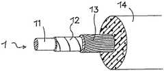
도 5에는, 본 발명의 일 실시예에 따른 또 다른 예시적인 누설 동축 안테나의 부분들의 측면도가 도시된다. 이 실시예에 따르면, 중심 또는 내부 도전체(1)는 US 5 500 488 A호에 설명된 원리들에 따른 상이한 구조를 포함한다. 이 실시예에 따르면, 내부 도전체(1)는 플라스틱 코어(11) 주위에 배치되며, 내부 도전체는 2 개의 층들(12 및 13)을 포함한다. 내부 층(12)은 겹쳐지고, 나선형으로 감싸진 전기 도전성 필름의 형태로 되어 있는 반면, 외부 층(13)은 상기 내부 층(12)과 전기적으로 접촉하는 서브된 와이어(served wire)들의 형태로 되어 있다. 상기 층(12)은 플라스틱 코어(11) 주위에 감싸진 은-도금된 구리 필름의 형태로 되어 있을 수 있으며, 이 실시예에서는 트위스트된 둥근 은-도금된 구리 도전체들(13)의 조합이 구리 필름(12) 위에 도포된다. 유전체(14)는 내부 도전체(1)를 덮는다. 이러한 구성으로, 광-대역 고 주파수 양립가능한(compatible) 전기 동축 케이블이 제공될 수 있으며, 이는 본 명세서에 설명된 안테나 특성들과 조합하여, 원하는 전기적, 기계적 특성들 및 제조 비용들을 최적화하는 저-감쇠(low-attenuation) 동축 케이블의 요건을 만족하는 광-대역 고 주파수 양립가능한 전송 특성들을 조합한다. 더욱이, 낮은 케이블 무게와 높은 유연성이 제공될 수 있다.5 is a side view of portions of another exemplary leaky coaxial antenna in accordance with an embodiment of the present invention. According to this embodiment, the center or
도 4는 각각의 부분들(AS1 내지 AS10) 간의 구체적인 거리들을 나타내는 본 발명의 또 다른 실시예에 따른 또 다른 예시적인 누설 동축 안테나의 측면도이다. 이 예시에 따르면, 상기 부분들(AS1 내지 AS10)의 폭(L)은 도시된 케이블 길이에 걸쳐 일정하게 유지된다.4 is a side view of another exemplary leaky coaxial antenna according to another embodiment of the present invention showing specific distances between the respective portions AS1 to AS10. According to this example, the width L of the parts AS1 to AS10 remains constant over the cable length shown.
그러므로, 본 발명은 누설 동축 안테나의 특성들을 개선하는 2-층 실드를 제안한다. 특히, 두 실드 층들은 케이블 벤딩을 허용하면서도, 제 2 실드 도전체를 포함하는 제 2 실드 층이 케이블 길이의 상당한 부분들에 걸쳐 제 1 실드 도전체를 포함하는 제 1 실드 층의 개구부들을 덮거나 차단하기 때문에, 동축 전달 모드의 길이 방향 손실이 현저히 감소될 수 있다. 이는 낮은 길이 방향 손실을 갖는 유연한 설계의 조합을 허용한다. 횡축 손실 또는 방사의 양, 또한 누설 동축 케이블의 대역폭 및 도달 길이는 제 1 실드 층의 포괄도, 또는 제 1 실드 층의 차단에 의해, 그리고 제 1 실드 층의 덮이지 않은 또는 차단되지 않은 부분들(제 2 실드 층의 개구부들)의 길이에 의해 제어될 수 있다. 이는 다수의 어플리케이션들에 본 발명의 적용을 허용한다. 이는 항공 우주 공학 어플리케이션들에서와 같이, 유연성과 조합하여 높은 대역폭과 긴 도달 길이가 요구되는 때에 특별한 중요성을 갖는다.Therefore, the present invention proposes a two-layer shield that improves the characteristics of a leaky coaxial antenna. In particular, the two shield layers allow for cable bending while the second shield layer comprising the second shield conductor covers the openings of the first shield layer including the first shield conductor over substantial portions of the cable length, or Because of the blocking, the longitudinal loss of the coaxial transfer mode can be significantly reduced. This allows for a combination of flexible designs with low longitudinal losses. The amount of transverse loss or radiation, and also the bandwidth and arrival length of the leaky coaxial cable, is determined by the comprehensiveness of the first shield layer, or by the blocking of the first shield layer, and the uncovered or unblocked portions of the first shield layer. It can be controlled by the length of the (openings of the second shield layer). This allows the application of the invention to many applications. This is of particular importance when high bandwidth and long reach are required in combination with flexibility, such as in aerospace engineering applications.
출원인은 본 발명의 동축 안테나의 예시들을 생성하였고, 상기 예시들을 종래의 동축 케이블들과 비교하였다. 이들 예시들 및 테스팅 결과들은 아래에 기록되어 있다.Applicant has generated examples of the coaxial antenna of the present invention and compared the examples with conventional coaxial cables. These examples and testing results are recorded below.
예시 1:Example 1:
본 발명에 따른 동축 안테나는 도 4에 도시된 바와 같이 구성되었다. 다음의 테스트들은 제안된 발명의 실제 유효성을 테스트하기 위해 수행되었다.The coaxial antenna according to the present invention has been constructed as shown in FIG. The following tests were performed to test the actual validity of the proposed invention.
다양한 직경들의 맨드릴(mandrel) 주위에서 180°로 도 4의 동축 안테나를 감싸고, 특성적 임피던스의 변화를 측정함으로써, 굴곡 반경이 측정되었다. 상기 특성적 임피던스는 시간 도메인 반사계(Time Domain Reflectometer)[TDR 샘플링 모듈 80E04를 갖는 텍트로닉스(Tektronix) TDS 8000]를 이용하여 측정되었다. 상기 결과들은 특성적 임피던스의 변화가 32 mm 이상의 맨드릴 직경에 대해 1 Ohm 미만이었음을 보여주었다. 이 테스트는 벤드(bend) 및/또는 몇몇 유연성을 요구하는 어플리케이션들에 동축 안테나가 사용될 수 있는 좋은 지표를 제공하였다.The bending radius was measured by wrapping the coaxial antenna of FIG. 4 at 180 ° around a mandrel of various diameters and measuring the change in characteristic impedance. The characteristic impedance was measured using a Time Domain Reflectometer (Tektronix TDS 8000 with TDR Sampling Module 80E04). The results showed that the change in characteristic impedance was less than 1 Ohm for mandrel diameters greater than 32 mm. This test provided a good indication that coaxial antennas could be used for applications that require bend and / or some flexibility.
예시 1의 동축 안테나의 주파수 응답은 애질런트(Agilent) 8753ES 벡터 네트워크 분석기를 이용하여 측정되었다. 삽입 손실(Insertion Loss: S21) 및 복귀 손실(Return Loss: S11)은 300 ㎑ 내지 6 ㎓의 주파수 범위에 걸쳐 측정되었다. 베이스라인 성능 레벨을 얻기 위해서, 이들 측정들은 먼저, 예시 1의 동축 안테나를 이용하여, 개구부들이 외부 제 2 실드 도전체 안에 놓여지기 이전에 수행(길이 방향 감쇠)되었으며, 그리고 이러한 개구부들이 동축 안테나 안으로 도입된 이후에 수행(길이 방향과 횡축방향 감쇠)되었다. 상기 결과들은 다음과 같았다: 베이스라인(비-안테나) 케이블은 2.5 ㎓에서 0.19 dB/m의 길이 방향 삽입 손실을 가졌고, 6 ㎓에서 0.31 dB/m의 길이 방향 삽입 손실을 가졌다. 개구부들이 도입된 후, 길이 방향과 횡축방향 손실의 조합은 2.5 ㎓에서 0.24 dB/m 그리고 6 ㎓에서 0.57 dB/m인 것으로 측정되었다. 누설 라인 안테나의 복귀 손실은 6 ㎓ 미만의 주파수들에 대해 -18 dB 미만인 것으로 측정되었다. 또한, 로데앤슈바르츠(Rhode & Schwarz)로부터의 벡터 네트워크 분석기 ZVCE를 이용하여 안테나 효율성을 유도하기 위해, 전달 임피던스(Transfer Impedance) 측정이 수행되었다. 상기 테스트는 실드된 공간에서 행해졌다. 국제전기기술위원회(International Electrotechnical Commission) 표준 문서 IEC 61196-1에 설명된 와이어 주입 방법이 20 ㎑ 내지 3 ㎓의 주파수 범위에 걸쳐 구현되었다. 테스트 샘플은 하나의 개구부를 갖는 0.5 m 길이의 동축 안테나였다. 양 단부들은 정의된 접지 조건들을 제공하도록 황동 픽스처(brass fixture) 안에서 종료된다. 안테나 효율성은 800 ㎒에서 -15 dB로 측정되었고, 2.5 ㎓에서 -10 dB로 측정되었다. 이들 실험들은 예시 1의 방사/누설 동축 안테나가 높은 대역폭, 즉 400 ㎒ 내지 6 ㎓을 나타내었다는 것을 보여주었다.The frequency response of the coaxial antenna of Example 1 was measured using an Agilent 8753ES vector network analyzer. Insertion Loss (S21) and Return Loss (S11) were measured over a frequency range of 300 Hz to 6 Hz. To obtain the baseline performance level, these measurements were first performed (length attenuation) before the openings were placed in the outer second shield conductor, using the coaxial antenna of Example 1, and these openings were introduced into the coaxial antenna. It was performed after introduction (length and transverse damping). The results were as follows: the baseline (non-antenna) cable had a 0.19 dB / m longitudinal insertion loss at 2.5 Hz and a 0.31 dB / m longitudinal insertion loss at 6 Hz. After the openings were introduced, the combination of longitudinal and transverse loss was measured to be 0.24 dB / m at 2.5 Hz and 0.57 dB / m at 6 Hz. The return loss of the leakage line antenna was measured to be less than -18 dB for frequencies below 6 Hz. In addition, a transfer impedance measurement was performed to derive antenna efficiency using a vector network analyzer ZVCE from Rhode & Schwarz. The test was done in a shielded space. The wire injection method described in the International Electrotechnical Commission standard document IEC 61196-1 has been implemented over a frequency range of 20 kHz to 3 kHz. The test sample was a 0.5 m long coaxial antenna with one opening. Both ends are terminated in a brass fixture to provide defined grounding conditions. Antenna efficiency was measured as -15 dB at 800 MHz and -10 dB at 2.5 kHz. These experiments showed that the radiation / leakage coaxial antenna of Example 1 exhibited high bandwidth, i.e. 400 MHz to 6 Hz.
수행된 또 다른 실험은 사용 시 시스템을 나타내는 실제 상황에서 예시 1의 동축 안테나를 설치(hook up)하는 것이었다: WLAN 네트워크는 2 개의 컴퓨터들 사이에 이 예시의 동축 안테나를 이용하여 생성되었다. WLAN 액세스 포인트[SMC EliteConnect Universal Wireless Access Point SMC2555W-AG]는 이 예시의 동축 안테나의 60 m에 연결되었다. 10 m 구간은 접지에서 약 2 미터 위에 현가되었고, 수신기는 현가된 안테나 밑의 다수의 지점들에 위치되었으며, 성능이 측정되었다. 수신기는 무선 LAN 카드[SMC EliteConnect Universal Wireless Cardbus Adapter SMC2536W-AG]를 갖는 모바일 컴퓨터[Dell® Lattitude]를 포함하였다. WLAN 링크 품질은 WLAN 안테나가 있는 소프트웨어를 이용하여 측정되었고, 현가된 안테나로부터 5 m 거리 내에서 최대 링크 품질을 나타내었다.Another experiment performed was to hook up the coaxial antenna of Example 1 in the actual situation representing the system in use: A WLAN network was created using this example coaxial antenna between two computers. A WLAN access point [SMC EliteConnect Universal Wireless Access Point SMC2555W-AG] was connected to 60 m of the coaxial antenna of this example. The 10 m section was suspended about 2 meters above ground, the receiver was located at multiple points below the suspended antenna, and performance was measured. The receiver included a mobile computer [Dell® Lattitude] with a wireless LAN card [SMC EliteConnect Universal Wireless Cardbus Adapter SMC2536W-AG]. WLAN link quality was measured using software with WLAN antennas, indicating the maximum link quality within 5 m of the suspended antenna.
본 발명의 특정 실시예들이 예시되고 설명되었지만, 본 발명은 이러한 예시와 설명으로 제한되지 않는다. 청구항들의 범위 내에서 변형들과 수정들이 통합될 수 있으며, 본 발명의 부분으로서 구현될 수 있다.While certain embodiments of the invention have been illustrated and described, the invention is not limited to these examples and descriptions. Variations and modifications may be incorporated within the scope of the claims and may be implemented as part of the invention.
Claims (13)
Translated fromKoreanApplications Claiming Priority (2)
| Application Number | Priority Date | Filing Date | Title |
|---|---|---|---|
| EP06002185AEP1816704B1 (en) | 2006-02-02 | 2006-02-02 | Leaky coaxial antenna |
| EP06002185.4 | 2006-02-02 |
Publications (2)
| Publication Number | Publication Date |
|---|---|
| KR20080100340A KR20080100340A (en) | 2008-11-17 |
| KR101067831B1true KR101067831B1 (en) | 2011-09-27 |
Family
ID=36001154
Family Applications (1)
| Application Number | Title | Priority Date | Filing Date |
|---|---|---|---|
| KR1020087019052AExpired - Fee RelatedKR101067831B1 (en) | 2006-02-02 | 2007-01-23 | Leakage coaxial antenna |
Country Status (14)
| Country | Link |
|---|---|
| US (1) | US7872611B2 (en) |
| EP (1) | EP1816704B1 (en) |
| JP (1) | JP4829314B2 (en) |
| KR (1) | KR101067831B1 (en) |
| AT (1) | ATE400909T1 (en) |
| AU (1) | AU2007211668B2 (en) |
| BR (1) | BRPI0707369A2 (en) |
| CA (1) | CA2641124C (en) |
| DE (1) | DE602006001728D1 (en) |
| ES (1) | ES2310378T3 (en) |
| PL (1) | PL1816704T3 (en) |
| RU (1) | RU2378747C1 (en) |
| WO (1) | WO2007087998A1 (en) |
| ZA (1) | ZA200804639B (en) |
Families Citing this family (54)
| Publication number | Priority date | Publication date | Assignee | Title |
|---|---|---|---|---|
| KR101043855B1 (en)* | 2009-01-13 | 2011-06-22 | 엘에스전선 주식회사 | Cable Type Broadband Antenna System |
| GB0914502D0 (en) | 2009-08-19 | 2009-09-30 | Rolls Royce Plc | Electrical conductor paths |
| CN102394329A (en)* | 2011-10-17 | 2012-03-28 | 江苏俊知技术有限公司 | Outer conductor leaky coaxial cable with novel double-layer winding |
| BR112016015619B1 (en)* | 2014-01-20 | 2022-03-15 | Telefonaktiebolaget Lm Ericsson (Publ) | ANTENNA SYSTEM AND METHOD TO PROVIDE COVERAGE FOR MIMO COMMUNICATION |
| RU2559755C1 (en)* | 2014-01-30 | 2015-08-10 | Юрий Пантелеевич Лепеха | Wideband antenna device based on radiating coaxial cable |
| US9601444B2 (en)* | 2014-02-27 | 2017-03-21 | Tektronix, Inc. | Cable mounted modularized signal conditioning apparatus system |
| US9973299B2 (en) | 2014-10-14 | 2018-05-15 | At&T Intellectual Property I, L.P. | Method and apparatus for adjusting a mode of communication in a communication network |
| US9312919B1 (en) | 2014-10-21 | 2016-04-12 | At&T Intellectual Property I, Lp | Transmission device with impairment compensation and methods for use therewith |
| US9997819B2 (en) | 2015-06-09 | 2018-06-12 | At&T Intellectual Property I, L.P. | Transmission medium and method for facilitating propagation of electromagnetic waves via a core |
| US10009067B2 (en) | 2014-12-04 | 2018-06-26 | At&T Intellectual Property I, L.P. | Method and apparatus for configuring a communication interface |
| US10243784B2 (en) | 2014-11-20 | 2019-03-26 | At&T Intellectual Property I, L.P. | System for generating topology information and methods thereof |
| US9544006B2 (en) | 2014-11-20 | 2017-01-10 | At&T Intellectual Property I, L.P. | Transmission device with mode division multiplexing and methods for use therewith |
| US9461706B1 (en) | 2015-07-31 | 2016-10-04 | At&T Intellectual Property I, Lp | Method and apparatus for exchanging communication signals |
| US9954287B2 (en) | 2014-11-20 | 2018-04-24 | At&T Intellectual Property I, L.P. | Apparatus for converting wireless signals and electromagnetic waves and methods thereof |
| US9876570B2 (en) | 2015-02-20 | 2018-01-23 | At&T Intellectual Property I, Lp | Guided-wave transmission device with non-fundamental mode propagation and methods for use therewith |
| US10224981B2 (en) | 2015-04-24 | 2019-03-05 | At&T Intellectual Property I, Lp | Passive electrical coupling device and methods for use therewith |
| US9705561B2 (en) | 2015-04-24 | 2017-07-11 | At&T Intellectual Property I, L.P. | Directional coupling device and methods for use therewith |
| US9490869B1 (en) | 2015-05-14 | 2016-11-08 | At&T Intellectual Property I, L.P. | Transmission medium having multiple cores and methods for use therewith |
| US9871282B2 (en) | 2015-05-14 | 2018-01-16 | At&T Intellectual Property I, L.P. | At least one transmission medium having a dielectric surface that is covered at least in part by a second dielectric |
| US10650940B2 (en)* | 2015-05-15 | 2020-05-12 | At&T Intellectual Property I, L.P. | Transmission medium having a conductive material and methods for use therewith |
| US10679767B2 (en) | 2015-05-15 | 2020-06-09 | At&T Intellectual Property I, L.P. | Transmission medium having a conductive material and methods for use therewith |
| US9917341B2 (en) | 2015-05-27 | 2018-03-13 | At&T Intellectual Property I, L.P. | Apparatus and method for launching electromagnetic waves and for modifying radial dimensions of the propagating electromagnetic waves |
| US9866309B2 (en) | 2015-06-03 | 2018-01-09 | At&T Intellectual Property I, Lp | Host node device and methods for use therewith |
| US9912381B2 (en) | 2015-06-03 | 2018-03-06 | At&T Intellectual Property I, Lp | Network termination and methods for use therewith |
| US9913139B2 (en) | 2015-06-09 | 2018-03-06 | At&T Intellectual Property I, L.P. | Signal fingerprinting for authentication of communicating devices |
| US9820146B2 (en) | 2015-06-12 | 2017-11-14 | At&T Intellectual Property I, L.P. | Method and apparatus for authentication and identity management of communicating devices |
| US9640850B2 (en) | 2015-06-25 | 2017-05-02 | At&T Intellectual Property I, L.P. | Methods and apparatus for inducing a non-fundamental wave mode on a transmission medium |
| US9865911B2 (en) | 2015-06-25 | 2018-01-09 | At&T Intellectual Property I, L.P. | Waveguide system for slot radiating first electromagnetic waves that are combined into a non-fundamental wave mode second electromagnetic wave on a transmission medium |
| US10044409B2 (en) | 2015-07-14 | 2018-08-07 | At&T Intellectual Property I, L.P. | Transmission medium and methods for use therewith |
| US9853342B2 (en) | 2015-07-14 | 2017-12-26 | At&T Intellectual Property I, L.P. | Dielectric transmission medium connector and methods for use therewith |
| US9847566B2 (en) | 2015-07-14 | 2017-12-19 | At&T Intellectual Property I, L.P. | Method and apparatus for adjusting a field of a signal to mitigate interference |
| US10090606B2 (en) | 2015-07-15 | 2018-10-02 | At&T Intellectual Property I, L.P. | Antenna system with dielectric array and methods for use therewith |
| US9871283B2 (en) | 2015-07-23 | 2018-01-16 | At&T Intellectual Property I, Lp | Transmission medium having a dielectric core comprised of plural members connected by a ball and socket configuration |
| US9912027B2 (en) | 2015-07-23 | 2018-03-06 | At&T Intellectual Property I, L.P. | Method and apparatus for exchanging communication signals |
| US9948333B2 (en) | 2015-07-23 | 2018-04-17 | At&T Intellectual Property I, L.P. | Method and apparatus for wireless communications to mitigate interference |
| US9749053B2 (en) | 2015-07-23 | 2017-08-29 | At&T Intellectual Property I, L.P. | Node device, repeater and methods for use therewith |
| US9967173B2 (en) | 2015-07-31 | 2018-05-08 | At&T Intellectual Property I, L.P. | Method and apparatus for authentication and identity management of communicating devices |
| US9904535B2 (en) | 2015-09-14 | 2018-02-27 | At&T Intellectual Property I, L.P. | Method and apparatus for distributing software |
| US9876264B2 (en) | 2015-10-02 | 2018-01-23 | At&T Intellectual Property I, Lp | Communication system, guided wave switch and methods for use therewith |
| US10355367B2 (en) | 2015-10-16 | 2019-07-16 | At&T Intellectual Property I, L.P. | Antenna structure for exchanging wireless signals |
| US9860075B1 (en) | 2016-08-26 | 2018-01-02 | At&T Intellectual Property I, L.P. | Method and communication node for broadband distribution |
| US10811767B2 (en) | 2016-10-21 | 2020-10-20 | At&T Intellectual Property I, L.P. | System and dielectric antenna with convex dielectric radome |
| US10312567B2 (en) | 2016-10-26 | 2019-06-04 | At&T Intellectual Property I, L.P. | Launcher with planar strip antenna and methods for use therewith |
| US10225025B2 (en) | 2016-11-03 | 2019-03-05 | At&T Intellectual Property I, L.P. | Method and apparatus for detecting a fault in a communication system |
| CN106340703B (en)* | 2016-11-16 | 2022-01-25 | 江苏亨鑫科技有限公司 | High-isolation three-coaxial leaky coaxial cable |
| US10178445B2 (en) | 2016-11-23 | 2019-01-08 | At&T Intellectual Property I, L.P. | Methods, devices, and systems for load balancing between a plurality of waveguides |
| US10637149B2 (en) | 2016-12-06 | 2020-04-28 | At&T Intellectual Property I, L.P. | Injection molded dielectric antenna and methods for use therewith |
| US10389037B2 (en) | 2016-12-08 | 2019-08-20 | At&T Intellectual Property I, L.P. | Apparatus and methods for selecting sections of an antenna array and use therewith |
| US9998870B1 (en) | 2016-12-08 | 2018-06-12 | At&T Intellectual Property I, L.P. | Method and apparatus for proximity sensing |
| US9838896B1 (en) | 2016-12-09 | 2017-12-05 | At&T Intellectual Property I, L.P. | Method and apparatus for assessing network coverage |
| RU180099U1 (en)* | 2017-06-26 | 2018-06-04 | Российская Федерация, от имени которой выступает Министерство обороны Российской Федерации | COAXIAL ANTENNA WITH ADVANCED OPERATING STRIP |
| CN110998975B (en)* | 2017-09-14 | 2022-07-22 | 株式会社藤仓 | leaky coaxial cable |
| WO2023118989A1 (en)* | 2021-12-21 | 2023-06-29 | Poynting Antennas (Pty) Limited | In-line signal distribution system |
| CN116799513B (en)* | 2023-08-17 | 2023-11-10 | 中天射频电缆有限公司 | A leaky transmission line signal gathering device and a leaky transmission component |
Citations (1)
| Publication number | Priority date | Publication date | Assignee | Title |
|---|---|---|---|---|
| US20040129841A1 (en)* | 2002-08-22 | 2004-07-08 | Senior Industries, Inc. | Drop wire clamp |
Family Cites Families (19)
| Publication number | Priority date | Publication date | Assignee | Title |
|---|---|---|---|---|
| US3870977A (en)* | 1973-09-25 | 1975-03-11 | Times Wire And Cable Companay | Radiating coaxial cable |
| US3963999A (en)* | 1975-05-29 | 1976-06-15 | The Furukawa Electric Co., Ltd. | Ultra-high-frequency leaky coaxial cable |
| DE2636523A1 (en)* | 1976-08-13 | 1978-02-16 | Kabel Metallwerke Ghh | RADIATING HIGH FREQUENCY LINE |
| DE2708070C3 (en)* | 1977-02-22 | 1980-09-04 | Aeg-Telefunken Kabelwerke Ag, Rheydt, 4050 Moenchengladbach | Radiating high frequency coaxial cable |
| JPS5457936U (en)* | 1977-09-28 | 1979-04-21 | ||
| JPS5457936A (en)* | 1977-10-18 | 1979-05-10 | Yagi Antenna | Method of fixing antenna element |
| US4339733A (en) | 1980-09-05 | 1982-07-13 | Times Fiber Communications, Inc. | Radiating cable |
| CA1195744A (en) | 1983-04-15 | 1985-10-22 | Hugh A. Edwards | Method of producing leaky coaxial cable |
| JPH04113727A (en)* | 1990-09-04 | 1992-04-15 | Ocean Cable Co Ltd | Indoor radio system and its transmission line |
| US5465395A (en)* | 1991-04-22 | 1995-11-07 | Bartram; David V. | Communication via leaky cables |
| RU2013832C1 (en) | 1991-08-09 | 1994-05-30 | Войсковая часть 60130 | Emitting coaxial cable |
| JPH0775286B2 (en)* | 1991-10-24 | 1995-08-09 | 株式会社小電力高速通信研究所 | Electromagnetic radiation cable |
| DE9310993U1 (en) | 1993-07-22 | 1994-11-17 | W.L. Gore & Associates Gmbh, 85640 Putzbrunn | Broadband radio frequency-compatible electrical coaxial cable |
| JP3734857B2 (en)* | 1995-07-24 | 2006-01-11 | 古河電気工業株式会社 | Leaky coaxial cable |
| CA2239642C (en)* | 1997-06-26 | 2001-05-29 | Geza Dienes | Antenna for radiating cable-to-vehicle communication systems |
| US5936203A (en) | 1997-10-15 | 1999-08-10 | Andrew Corporation | Radiating coaxial cable with outer conductor formed by multiple conducting strips |
| US6480163B1 (en)* | 1999-12-16 | 2002-11-12 | Andrew Corporation | Radiating coaxial cable having helically diposed slots and radio communication system using same |
| US6878147B2 (en)* | 2001-11-02 | 2005-04-12 | Vivant Medical, Inc. | High-strength microwave antenna assemblies |
| RU2207670C1 (en) | 2002-04-04 | 2003-06-27 | Орлов Александр Борисович | Antenna |
- 2006
- 2006-02-02EPEP06002185Apatent/EP1816704B1/ennot_activeNot-in-force
- 2006-02-02ESES06002185Tpatent/ES2310378T3/enactiveActive
- 2006-02-02DEDE602006001728Tpatent/DE602006001728D1/enactiveActive
- 2006-02-02ATAT06002185Tpatent/ATE400909T1/enactive
- 2006-02-02PLPL06002185Tpatent/PL1816704T3/enunknown
- 2007
- 2007-01-23BRBRPI0707369-0Apatent/BRPI0707369A2/ennot_activeApplication Discontinuation
- 2007-01-23AUAU2007211668Apatent/AU2007211668B2/ennot_activeCeased
- 2007-01-23WOPCT/EP2007/000554patent/WO2007087998A1/enactiveApplication Filing
- 2007-01-23KRKR1020087019052Apatent/KR101067831B1/ennot_activeExpired - Fee Related
- 2007-01-23CACA2641124Apatent/CA2641124C/ennot_activeExpired - Fee Related
- 2007-01-23USUS12/162,191patent/US7872611B2/enactiveActive
- 2007-01-23JPJP2008552721Apatent/JP4829314B2/ennot_activeExpired - Fee Related
- 2007-01-23RURU2008135436/09Apatent/RU2378747C1/ennot_activeIP Right Cessation
- 2007-01-23ZAZA200804639Apatent/ZA200804639B/enunknown
Patent Citations (1)
| Publication number | Priority date | Publication date | Assignee | Title |
|---|---|---|---|---|
| US20040129841A1 (en)* | 2002-08-22 | 2004-07-08 | Senior Industries, Inc. | Drop wire clamp |
Also Published As
| Publication number | Publication date |
|---|---|
| PL1816704T3 (en) | 2008-11-28 |
| ATE400909T1 (en) | 2008-07-15 |
| WO2007087998A1 (en) | 2007-08-09 |
| JP2009525646A (en) | 2009-07-09 |
| JP4829314B2 (en) | 2011-12-07 |
| CA2641124C (en) | 2013-03-19 |
| AU2007211668A8 (en) | 2008-07-10 |
| US20090303149A1 (en) | 2009-12-10 |
| US7872611B2 (en) | 2011-01-18 |
| AU2007211668B2 (en) | 2011-03-31 |
| ZA200804639B (en) | 2009-11-25 |
| EP1816704B1 (en) | 2008-07-09 |
| CA2641124A1 (en) | 2007-08-09 |
| BRPI0707369A2 (en) | 2011-05-03 |
| KR20080100340A (en) | 2008-11-17 |
| DE602006001728D1 (en) | 2008-08-21 |
| ES2310378T3 (en) | 2009-01-01 |
| AU2007211668A1 (en) | 2007-08-09 |
| EP1816704A1 (en) | 2007-08-08 |
| RU2378747C1 (en) | 2010-01-10 |
Similar Documents
| Publication | Publication Date | Title |
|---|---|---|
| KR101067831B1 (en) | Leakage coaxial antenna | |
| US9577341B2 (en) | Microcellular communications antenna and associated methods | |
| Elmore | Introduction to the propagating wave on a single conductor | |
| JP4742154B2 (en) | Leakage cable | |
| JPS588253U (en) | Wireless communication device for confined spaces | |
| JP2012175707A (en) | Antenna protection device and system | |
| EP2587586A1 (en) | Distributed antenna system and method of manufacturing a distributed antenna system | |
| CN101286591A (en) | Broadband antenna | |
| EP3460912B1 (en) | Communications antenna and associated methods | |
| Engelbrecht et al. | First results of a leaky coaxial cable prototype for indoor positioning | |
| WO2022162037A1 (en) | Radiating coaxial cable | |
| US6781051B1 (en) | Radiating cable | |
| CA3017389C (en) | Managed access system including surface wave antenna and related methods | |
| JP5200132B2 (en) | LCX communication device | |
| JP6469029B2 (en) | Cable type antenna | |
| McReynolds | Choosing The Right RF Cable Assembly | |
| GB2407914A (en) | A Cable with low radar reflections | |
| JP2017139730A (en) | Cable type antenna | |
| JP2000232319A (en) | Antenna |
Legal Events
| Date | Code | Title | Description |
|---|---|---|---|
| PA0105 | International application | St.27 status event code:A-0-1-A10-A15-nap-PA0105 | |
| P11-X000 | Amendment of application requested | St.27 status event code:A-2-2-P10-P11-nap-X000 | |
| P11-X000 | Amendment of application requested | St.27 status event code:A-2-2-P10-P11-nap-X000 | |
| P13-X000 | Application amended | St.27 status event code:A-2-2-P10-P13-nap-X000 | |
| P11-X000 | Amendment of application requested | St.27 status event code:A-2-2-P10-P11-nap-X000 | |
| P13-X000 | Application amended | St.27 status event code:A-2-2-P10-P13-nap-X000 | |
| PG1501 | Laying open of application | St.27 status event code:A-1-1-Q10-Q12-nap-PG1501 | |
| PE0801 | Dismissal of amendment | St.27 status event code:A-2-2-P10-P12-nap-PE0801 | |
| A201 | Request for examination | ||
| P11-X000 | Amendment of application requested | St.27 status event code:A-2-2-P10-P11-nap-X000 | |
| P13-X000 | Application amended | St.27 status event code:A-2-2-P10-P13-nap-X000 | |
| PA0201 | Request for examination | St.27 status event code:A-1-2-D10-D11-exm-PA0201 | |
| E902 | Notification of reason for refusal | ||
| PE0902 | Notice of grounds for rejection | St.27 status event code:A-1-2-D10-D21-exm-PE0902 | |
| T11-X000 | Administrative time limit extension requested | St.27 status event code:U-3-3-T10-T11-oth-X000 | |
| P11-X000 | Amendment of application requested | St.27 status event code:A-2-2-P10-P11-nap-X000 | |
| P13-X000 | Application amended | St.27 status event code:A-2-2-P10-P13-nap-X000 | |
| E701 | Decision to grant or registration of patent right | ||
| PE0701 | Decision of registration | St.27 status event code:A-1-2-D10-D22-exm-PE0701 | |
| GRNT | Written decision to grant | ||
| PR0701 | Registration of establishment | St.27 status event code:A-2-4-F10-F11-exm-PR0701 | |
| PR1002 | Payment of registration fee | St.27 status event code:A-2-2-U10-U12-oth-PR1002 Fee payment year number:1 | |
| PG1601 | Publication of registration | St.27 status event code:A-4-4-Q10-Q13-nap-PG1601 | |
| FPAY | Annual fee payment | Payment date:20140905 Year of fee payment:4 | |
| PR1001 | Payment of annual fee | St.27 status event code:A-4-4-U10-U11-oth-PR1001 Fee payment year number:4 | |
| PR1001 | Payment of annual fee | St.27 status event code:A-4-4-U10-U11-oth-PR1001 Fee payment year number:5 | |
| P22-X000 | Classification modified | St.27 status event code:A-4-4-P10-P22-nap-X000 | |
| PR1001 | Payment of annual fee | St.27 status event code:A-4-4-U10-U11-oth-PR1001 Fee payment year number:6 | |
| PR1001 | Payment of annual fee | St.27 status event code:A-4-4-U10-U11-oth-PR1001 Fee payment year number:7 | |
| FPAY | Annual fee payment | Payment date:20180903 Year of fee payment:8 | |
| PR1001 | Payment of annual fee | St.27 status event code:A-4-4-U10-U11-oth-PR1001 Fee payment year number:8 | |
| PC1903 | Unpaid annual fee | St.27 status event code:A-4-4-U10-U13-oth-PC1903 Not in force date:20190921 Payment event data comment text:Termination Category : DEFAULT_OF_REGISTRATION_FEE | |
| PC1903 | Unpaid annual fee | St.27 status event code:N-4-6-H10-H13-oth-PC1903 Ip right cessation event data comment text:Termination Category : DEFAULT_OF_REGISTRATION_FEE Not in force date:20190921 | |
| P22-X000 | Classification modified | St.27 status event code:A-4-4-P10-P22-nap-X000 |