KR101066164B1 - Endoscopic Suture Device - Google Patents
Endoscopic Suture DeviceDownload PDFInfo
- Publication number
- KR101066164B1 KR101066164B1KR1020100118171AKR20100118171AKR101066164B1KR 101066164 B1KR101066164 B1KR 101066164B1KR 1020100118171 AKR1020100118171 AKR 1020100118171AKR 20100118171 AKR20100118171 AKR 20100118171AKR 101066164 B1KR101066164 B1KR 101066164B1
- Authority
- KR
- South Korea
- Prior art keywords
- suture
- actuator
- needle
- cylinder
- endoscope
- Prior art date
- Legal status (The legal status is an assumption and is not a legal conclusion. Google has not performed a legal analysis and makes no representation as to the accuracy of the status listed.)
- Expired - Fee Related
Links
Images


Classifications
- A—HUMAN NECESSITIES
- A61—MEDICAL OR VETERINARY SCIENCE; HYGIENE
- A61B—DIAGNOSIS; SURGERY; IDENTIFICATION
- A61B17/00—Surgical instruments, devices or methods
- A61B17/04—Surgical instruments, devices or methods for suturing wounds; Holders or packages for needles or suture materials
- A61B17/06—Needles ; Sutures; Needle-suture combinations; Holders or packages for needles or suture materials
- A61B17/062—Needle manipulators
- A—HUMAN NECESSITIES
- A61—MEDICAL OR VETERINARY SCIENCE; HYGIENE
- A61B—DIAGNOSIS; SURGERY; IDENTIFICATION
- A61B17/00—Surgical instruments, devices or methods
- A61B17/04—Surgical instruments, devices or methods for suturing wounds; Holders or packages for needles or suture materials
- A61B17/0469—Suturing instruments for use in minimally invasive surgery, e.g. endoscopic surgery
- A—HUMAN NECESSITIES
- A61—MEDICAL OR VETERINARY SCIENCE; HYGIENE
- A61B—DIAGNOSIS; SURGERY; IDENTIFICATION
- A61B34/00—Computer-aided surgery; Manipulators or robots specially adapted for use in surgery
- A61B34/70—Manipulators specially adapted for use in surgery
- A—HUMAN NECESSITIES
- A61—MEDICAL OR VETERINARY SCIENCE; HYGIENE
- A61B—DIAGNOSIS; SURGERY; IDENTIFICATION
- A61B17/00—Surgical instruments, devices or methods
- A61B17/00234—Surgical instruments, devices or methods for minimally invasive surgery
- A61B2017/00292—Surgical instruments, devices or methods for minimally invasive surgery mounted on or guided by flexible, e.g. catheter-like, means
- A61B2017/00296—Surgical instruments, devices or methods for minimally invasive surgery mounted on or guided by flexible, e.g. catheter-like, means mounted on an endoscope
- A—HUMAN NECESSITIES
- A61—MEDICAL OR VETERINARY SCIENCE; HYGIENE
- A61B—DIAGNOSIS; SURGERY; IDENTIFICATION
- A61B17/00—Surgical instruments, devices or methods
- A61B17/00234—Surgical instruments, devices or methods for minimally invasive surgery
- A61B2017/00292—Surgical instruments, devices or methods for minimally invasive surgery mounted on or guided by flexible, e.g. catheter-like, means
- A61B2017/0034—Surgical instruments, devices or methods for minimally invasive surgery mounted on or guided by flexible, e.g. catheter-like, means adapted to be inserted through a working channel of an endoscope
- A—HUMAN NECESSITIES
- A61—MEDICAL OR VETERINARY SCIENCE; HYGIENE
- A61B—DIAGNOSIS; SURGERY; IDENTIFICATION
- A61B34/00—Computer-aided surgery; Manipulators or robots specially adapted for use in surgery
- A61B34/30—Surgical robots
- A61B2034/301—Surgical robots for introducing or steering flexible instruments inserted into the body, e.g. catheters or endoscopes
Landscapes
- Health & Medical Sciences (AREA)
- Surgery (AREA)
- Life Sciences & Earth Sciences (AREA)
- Engineering & Computer Science (AREA)
- Heart & Thoracic Surgery (AREA)
- Biomedical Technology (AREA)
- Nuclear Medicine, Radiotherapy & Molecular Imaging (AREA)
- Medical Informatics (AREA)
- Molecular Biology (AREA)
- Animal Behavior & Ethology (AREA)
- General Health & Medical Sciences (AREA)
- Public Health (AREA)
- Veterinary Medicine (AREA)
- Robotics (AREA)
- Surgical Instruments (AREA)
Abstract
Translated fromKoreanDescription
Translated fromKorean본 발명은 내시경을 이용하여 인체 내부로 삽입 가능한 관체 내부로 각각 모터에 결합된 제1,2,3 레버로 연결 구성한 위치조절수단에 의해 봉합 부위 위치로 이동조절하도록 구성하여 상기 제1,2,3 레버가 각각 상하 회전 및 전후, 좌우 틸딩하면서 위치 조절하여 봉합 부위의 위치 이동, 바늘로 수술 부위를 봉합하거나 봉합한 실을 엮어 고정 및 절단하는 작업을 간단히 행하므로 시술 작업성을 우수하게 제공하는 내시경 봉합장치에 관한 것이다.
The present invention is configured to move to the suture site position by the position adjusting means configured by connecting the first, second, and third levers coupled to the motor into the tube insertable into the human body using the endoscope, respectively; 3 Lever rotates up and down, front and rear, right and left, respectively, and adjusts the position to move the position of the suture site, and to sew or fix the stitched thread with a needle to easily fix and cut. It relates to an endoscope suture device.
최근 신체 내부의 절개 수술은 내시경을 이용하여 최소의 절개 상태로 정밀하게 시술하는 방법들이 많이 사용되고 있다.Recently, the internal surgery of the body has been used a lot of methods to precisely perform a minimal incision state using an endoscope.
특히 상기 내시경 시술은 환자의 고통을 줄여줌은 물론 회복이 빠르게 진행되는 여러 잇점을 갖는 것이다.In particular, the endoscopic procedure is to reduce the pain of the patient as well as to have a number of advantages that the recovery proceeds quickly.
이와 같은 내시경 시술은 신체 내부의 병변부위로 기계 장치를 삽입하여 렌즈나 카메라 형태의 내시경으로 병병부위를 확인하면서 병변부위의 시술 및 봉합까지 행하는 것이다.Such endoscopy is performed by inserting a mechanical device into the lesion site of the body and checking the lesion site with a lens or camera-type endoscope and performing the procedure and suture of the lesion site.
예를 들면, 대한민국특허 공개특허 제10-2010-291, 제10-2006-92838호 및 등록특허 제10-531496호 등에서 수술 봉합장치가 다양하게 개시된 바 있는데, 이러한 종래 장치는 봉합 부위로 장치를 이동 조절하는 작업이 매우 불편하고, 신체의 봉합부위를 봉합사로 꿰매어 봉합하는 작업은 물론 봉합사를 엮어 고정하거나 절단하는 작업이 매우 불편하여 시술 작업성이 저하되는 문제점이 있었다.For example, various surgical suture devices have been disclosed in Korean Patent Laid-Open Publication Nos. 10-2010-291, 10-2006-92838, and Patent No. 10-531496. The movement control operation is very inconvenient, the work of sewing the suture part of the body with a suture, as well as the work of weaving and fixing or cutting the suture was very inconvenient, there was a problem that the procedure workability is lowered.
뿐만 아니라 상기와 같이 수술 작업성이 불편하여 시술의 숙련된 기술이 요구됨은 물론 시술 시간이 장기화되어 환자의 고통이 증가되는 여러 문제점을 유발하였다.
In addition, as described above, the operation workability is inconvenient, and the skilled technique of the procedure is required, as well as prolonging the treatment time, causing various problems in which the pain of the patient is increased.
본 발명은 상기한 종래 기술이 갖는 봉합 부위로 장치를 이동 조절, 봉합사를 엮어 고정/절단 작업 및 시술 시간이 장기화 등의 제반 문제점을 해결하고자 발명된 것으로서, 상기 관체 내부에 상하 회전 및 전후, 좌우 틸딩 이동조절되고, 봉합 부위를 꼬매는 바늘을 갖는 제1레버와, 상하 회전 및 전후, 좌우 틸딩 이동조절되고, 봉합사를 파지하는 가압구를 갖는 제2레버와, 상하 회전 및 전후, 좌우 틸딩 이동조절되고, 내시경을 이용하여 신체 내부의 수술부위를 봉합하되, 엑튜에이터와 와이어로 연결 구성하여 엑튜에이터에 의해 수술부위를 봉합하는 바늘과, 상기 실린더 하부에 고정구와 후단에 엑튜에이터와 와이어로 연결되는 가압구, 상기 봉합사를 파지 및 절단하고 엑튜에이터(50)와 와이어(51)로 연결되되 전후로 절단날(321)과 가압부(322)를 신체의 봉합 부위에서 각각 상하 회전 및 전후, 좌우 틸딩하여 위치 조절하면서 바늘로 수술 부위를 봉합하거나 봉합한 실을 엮어 고정 및 절단하는 작업을 간단히 행하므로 시술 작업성을 우수하게 제공하는데 그 목적이 있다.The present invention has been invented to solve various problems such as moving the device to the suture site of the prior art described above, weaving the suture and fixing / cutting work and prolonging the procedure time, vertical rotation and back and forth, left and right inside the tube A first lever having a tilting movement control and a needle for tying the suture portion, a second lever having a pressing hole for vertically rotating and front and rear, left and right tilting movement control, and holding a suture, and a vertical rotation, front and rear, left and right tilting movement It is controlled, and sutures the surgical site inside the body by using an endoscope, and is connected to the actuator and the wire to configure the needle to suture the surgical site by the actuator, and the fixture and the lower end of the cylinder connected to the actuator and the wire Pressurized opening, the gripping and cutting the suture is connected to the
본 발명은 시술 작업성이 간편하고 우수하여 수술 작업시간을 단축하고, 이로 인해 환자의 고통을 최소화하므로 사용 신뢰도를 우수하게 제공하는데 그 목적이 있다.The present invention aims to provide excellent operation reliability because the operation workability is simple and excellent to shorten the operation time, thereby minimizing the pain of the patient.
또한, 본 발명은 봉합 부위를 봉합사로 효과적으로 꿰매어 봉합하므로 사용 만족도를 우수하게 제공하는데 그 목적이 있다.
In addition, the present invention is to sew and suture the suture portion effectively with a suture is to provide an excellent use satisfaction.
이러한 본 발명은, 인체 내부로 삽입 가능한 관체를 구비하고, 상기 관체 내부에 상하 회전 및 전후, 좌우 틸딩 이동조절되고, 봉합 부위를 꼬매는 바늘을 갖는 제1레버와, 상하 회전 및 전후, 좌우 틸딩 이동조절되고, 봉합사를 파지하는 가압구를 갖는 제2레버와, 상하 회전 및 전후, 좌우 틸딩 이동조절되고, 봉합사를 파지 및 절단하여 주는 고정구와 절단날과 가압부를 갖는 제3레버로 구성함에 그 특징이 있다.The present invention includes a first body having a tube insertable into the human body, the first lever having a needle for fastening up and down, front and rear, left and right tilding movement adjustment, and stitching a suture site, and vertically rotating and front and rear, right and left tilting It consists of a second lever having a movement control, a pressing lever for holding the suture, and a third lever having a cutting device and a cutting blade and a pressing portion for vertically rotating, front and rear, left and right tilding movement control, holding and cutting the suture. There is a characteristic.
본 발명은 실린더 하부에 선단으로 봉합사를 삽입하는 바늘 구멍이 형성된 만곡형의 바늘의 레버부와 힌지 연결하여 바늘이 힌지를 중심으로 회동 가능케 연결하고, 상기 레버 타측과 실린더 상부의 엑튜에이터와 와이어로 연결 구성하여 상기 엑튜에이터에 의해 바늘이 힌지를 중심으로 회동하면서 봉합하도록 구성함에 그 특징이 있다.The present invention is connected to the hinge of the lever of the curved needle formed by the needle hole for inserting the suture to the lower end of the cylinder by connecting the needle pivotally around the hinge, and the actuator and wire on the other side of the lever and the cylinder It is characterized in that it is configured to seal while rotating the needle around the hinge by the actuator configuration.
본 발명은 인체 내부로 삽입 가능한 관체 내부로 중앙 실린더에 수평 설치된 제1모터의 모터축에 축 결합되어 상하 회전하는 제1레버와, 수직 설치된 제2,3모터의 모터축에 축 결합되되 상호 직교 방향으로 위치되어 전후, 좌우 틸딩하는 제2,3레버로 연결 구성한 위치조절수단에 의해 봉합 부위 위치로 상하 회전 및 전후, 좌우 틸딩 이동조절하도록 구성함에 그 특징이 있다.The present invention is coupled to the motor shaft of the first and the second lever and the vertically installed motor shaft of the first motor and the vertically coupled to the motor shaft of the first motor horizontally installed in the center cylinder into the tube insertable into the human body, but mutually orthogonal It is characterized in that it is configured to adjust the vertical rotation and the front and rear, left and right tilding movement to the position of the suture by the position adjusting means connected to the second and third levers which are positioned in the direction and connected to the second and third levers.
본 발명은 실린더 하부에 고정구와 후단에 엑튜에이터와 와이어로 연결되는 가압구를 중앙이 힌지 결합되게 "X"자 형태로 구비하여 상기 엑튜에이터에 의해 봉합사를 파지하도록 구성함에 그 특징이 있다.The present invention is characterized in that it is configured to hold the suture by the actuator provided with a "X" shape to the hinge is connected to the center and the actuator is connected to the wire and the actuator at the lower end of the cylinder.
본 발명은 실린더 하부에 전후로 고정날과 고정부를 일체 형성하는 고정구와, 후단에 엑튜에이터와 와이어로 연결되되 전후로 절단날과 가압부를 일체 형성하는 가압구를 중앙이 힌지 결합되게 "X"자 형태로 구비하여 상기 엑튜에이터에 의해 전후에서 봉합사를 파지하거나 절단하도록 구성함에 그 특징이 있다.The present invention is the "X" shape to be coupled to the center of the fasteners to form the fixed blade and the fixed portion integrally in the lower and rear cylinder, and the actuator and the wire is connected to the rear end of the cylinder at the rear end of the cylinder. It is characterized in that it is configured to hold or cut the suture before and after by the actuator.
본 발명은 가압구와 가압구의 가압부에는 봉합사를 탄발 파지하기 위해 요홈부에서 스프링에 의해 탄발 돌출되는 가압편이 설치 구성함에 그 특징이 있다.
The present invention is characterized in that the pressurizing piece protruding by the spring in the groove in the pressurizing portion of the pressurizing port and the pressurizing port in order to hold the sutures.
이러한 본 발명은 내시경을 이용하여 신체 내부의 수술부위를 봉합하되, 끝단에 수술부위를 봉합하는 바늘과, 상기 실린더 하부에 고정구와 후단에 엑튜에이터와 와이어로 연결되는 가압구와, 상기 봉합사를 파지 및 절단하고 엑튜에이터와 와이어로 연결되되 전후로 절단날과 가압부를 갖는 제1,2,3 레버를 각각 상하 회전 및 전후, 좌우 틸딩하여 위치 조절하면서 봉합 부위의 위치 이동, 바늘로 수술 부위를 봉합하거나 봉합한 실을 엮어 고정 및 절단하는 작업을 간단히 행하므로 시술 작업성을 우수하게 제공함은 물론 시술 작업성이 간편하고 우수하여 수술 작업시간의 단축과 이로 인해 환자의 고통을 최소화하므로 사용 신뢰도를 우수하게 제공하는 효과를 갖는 것이다.
The present invention sutures the surgical site inside the body using an endoscope, a needle for suturing the surgical site at the end, a pressurization port connected to the actuator and a wire at the rear end of the cylinder with a fixture and a gripping the suture and Cutting and connecting the actuator and the wire, the first, second, and third levers having cutting blades and pressing parts back and forth, left and right, respectively, by tilting the position to move the position of the suture, suture or suture the surgical site with a needle It is easy to fix and cut a single thread so that the operation is excellent and the operation is easy and excellent, so the operation time is shortened and the pain of the patient is minimized. It is to have the effect.
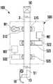
도 1은 본 발명 장치의 횡 단면 배열 구조를 보여주는 개념도.
도 2는 본 발명 장치의 제1모듈을 보여주는 정면 구성도.
도 3은 도 2의 요부도.
도 4는 본 발명 장치의 제2모듈을 보여주는 정면 구성도.
도 5는 도 4의 요부도
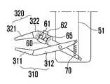
도 6은 본 발명 장치의 제3모듈을 보여주는 정면 구성도.
도 7은 도 6의 요부도
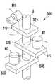
도 8은 본 발명 장치의 위치조절수단을 보여주는 사시도.
도 9는 도 8의 요부 평면도.
도 10 내지 도 15는 본 발명의 장치에 의한 봉합 과정을 보여주는 순서도.1 is a conceptual diagram showing a cross-sectional arrangement of the device of the present invention.
Figure 2 is a front configuration diagram showing a first module of the present invention device.
3 is a main view of FIG. 2;
Figure 4 is a front configuration diagram showing a second module of the present invention device.
5 is a main view of FIG.
Figure 6 is a front configuration diagram showing a third module of the present invention device.
7 is a main view of FIG.
Figure 8 is a perspective view showing the position adjusting means of the device of the present invention.
9 is a plan view of main parts of FIG. 8;
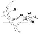
10 to 15 are flow charts showing the suture process by the device of the present invention.
이하, 상기한 본 발명의 바람직한 실시 예를 첨부도면을 참조하여 구체적으로 살펴보기로 한다.Hereinafter, preferred embodiments of the present invention will be described in detail with reference to the accompanying drawings.
본 발명 내시경 봉합장치는 도 1 내지 도 9에 도시된 바와 같이, 인체 내부로 삽입 가능한 관체(2)를 구비하고,The endoscope sealing device of the present invention, as shown in Figures 1 to 9, having a tubular body (2) that can be inserted into the human body,
상기 관체 내부에 상하 회전 및 전후, 좌우 틸딩 이동조절되고, 봉합 부위를 꼬매는 바늘(10)을 갖는 제1모듈(100)과,A
상하 회전 및 전후, 좌우 틸딩 이동조절되고, 봉합사를 파지하여 묶어주는 클램프(20)를 갖는 제2모듈(200)과,A
상하 회전 및 전후, 좌우 틸딩 이동조절되고, 봉합사를 파지 및 절단하여 주는 클램프 겸용 커터(30)를 갖는 제3모듈(300)로 구성하여 이루어진다.Up and down rotation, front and rear, left and right tilding movement is adjusted, consisting of a
이때, 상기 제1,2,3모듈(100)(200)(300)은 각각 별도의 관체(2)에 독립적으로 삽입 구성하여 사용할 수도 있음은 물론이다.At this time, the first, second, third module (100, 200, 300) may be used separately inserted into the separate pipe (2), of course.
즉, 상기 제1모듈(100)과, 제2모듈(200) 및 제3모듈(300)을 각각 구비하여 제1,2,3 모듈을 독립적으로 인체 내부에 삽입하여 봉합 작업하도록 구성할 수도 있는 것이다.That is, the
그리고 상기 제1,2,3모듈(100)(200)(300)은 공통적으로 봉합 부위 위치로 상하 회전 및 전후, 좌우 틸딩 이동조절하기 위한 위치조절수단(500)을 마련하여 구성된다.In addition, the first, second and
이는 제1,2,3모듈는 중앙 실린더(3)에 수평 설치된 제1모터(M1)의 모터축에 축 결합되어 상하 회전하는 제1레버(512)와, 수직 설치된 제2,3모터(M2)(M3)의 모터축에 축 결합되되, 상호 직교 방향으로 위치되어 전후, 좌우 틸딩하는 제2,3레버(522)(532)로 연결 구성하여 이룬다.This is because the first, second and third modules are axially coupled to the motor shaft of the first motor M1 horizontally installed on the
이때, 상기 제1,2,3레버(512)(522)(532)는 실린더(3)와 볼 조인트(515)(525)(535)로 각각 연결되어 회전 및 전후, 좌우 틸딩 이동이 복합된 이동이 가능하도록 구성된다.At this time, the first, second, and
또한, 상기 제1,2,3모터(M1)(M2)(M3)는 감속기, 모터, 엔코더가 결합된 직류 감속기 모터로 적용함이 바람직하다.In addition, the first, second, third motor (M1) (M2) (M3) is preferably applied as a reducer, motor, encoder DC coupled reducer motor.
그리고 상기 제1모듈(100)은 도 2 및 도 3에서와 같이 중심부에 구성된 힌지(11)를 중심으로 바늘부와 레버부(13)로 구성되는 바늘(10)과 연결된다.The
상기 바늘부는 선단에 봉합사를 삽입하는 바늘 구멍(12)이 형성된 만곡형으로 구성되고 상기 레버부(13)는 후단에 와이어(51)를 삽입하는 관통공이 형성된 직선형으로 구성되어 상기 레버부(13)의 관통공과 실린더(3) 상부의 엑튜에이터(50)와 와이어(51)로 연결 구성하여 상기 엑튜에이터(50)에 의해 바늘(10)이 힌지(11)를 중심으로 회동하면서 봉합하도록 구성된다.The needle part is formed in a curved shape formed with a
상기 제2모듈(200)은 도 4 및 도 5에서와 같이 실린더 하부에 고정구(210)와 후단에 엑튜에이터(50)와 와이어(51)로 연결되는 가압구(220)를 중앙이 힌지 결합되게 "X"자 형태로 구비하여 상기 엑튜에이터에 의해 봉합사를 파지하도록 구성된다.As shown in FIGS. 4 and 5, the
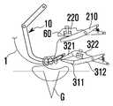
상기 제3모듈(300)은 도 6 및 도 7에서와 같이 실린더 하부에 전후로 고정날(311)과 고정부(312)를 일체 형성하는 고정구(310)와, 후단에 엑튜에이터(50)와 와이어(51)로 연결되되 전후로 절단날(321)과 가압부(322)를 일체 형성하는 가압구(320)를 중앙이 힌지 결합되게 "X"자 형태로 구비하여 상기 엑튜에이터에 의해 전후에서 봉합사를 파지하거나 절단하도록 구성된다.As shown in FIGS. 6 and 7, the
그리고, 상기 제2모듈(200)의 가압구(220)과 제3모듈(300) 가압구(320)의 가압부(322)에는 봉합사를 탄발 파지하기 위해 요홈부(61)에서 스프링(65)에 의해 탄발 돌출되는 가압편(60)이 설치 구성된다.In addition, the
미설명부호로서, 62는 가압편(60)을 지지하는 지지볼트, 70은 복귀 스프링을 나타내는 것이다.
다음은 상기와 같이 구성되는 본 발명의 작동 및 작용에 대해 살펴보기로 한다.Hereinafter, the operation and operation of the present invention will be described.
먼저 본 발명의 장치를 신체의 봉합 부위(G)로 삽입시켜 위치시킨다.First, the device of the present invention is inserted and placed into the suture site G of the body.
이 상태에서 관체(2) 내부의 제1,2,3모듈(100)(200)(300)을 각각의 위치조절수단(500)을 이용하여 내시경으로 관찰하며 상하 회전 및 전후, 좌우 틸딩 이동 조절하여 봉합 부위(G)로 이동시킨다.In this state, the first, second, and
이는 제1모터(M1)의 모터축에 축 결합된 제1레버(512)에 의해 제1,2,3모듈의 중앙 실린더(3)를 상하 회전 조절함과, 제2,3모터(M2)(M3)의 모터축에 축 결합되되, 상호 직교 방향으로 위치된 제2,3레버(522)(532)에 의해 제1,2,3모듈의 중앙 실린더(3)를 전후, 좌우로 틸딩 조절하여 가능하게 된다.This is to adjust the upper and lower rotation of the central cylinder (3) of the first, second and third modules by the
즉, 상기 제1,2,3모터(M1)(M2)(M3)의 구동 제어에 의한 제1,2,3레버(512)(522)(532)에 의해 제1,2,3모듈의 중앙 실린더(3)를 상하 회전 및 전후, 좌우 틸딩에 의한 복합 이동으로 봉합 부위(G)로 간단히 이동시키게 되는 것이다.That is, the first, second and third motors of the first, second and third modules are controlled by the first, second and
이와 같이 제1,2,3모듈을 봉합 부위로 위치시킨 상태로 상기 제1,2,3모듈(100)(200)(300)을 개별적으로 각각 조작하여 봉합사(1)에 의해 봉합부위(G)를 봉합하는 시술을 행하는 것이다.In this manner, the first, second,
이를 좀더 구체적으로 설명하면, 제1모듈(100)의 바늘(10)이 봉합 부위 일측에 위치하도록 위치 조절 상태에서, 엑튜에이터(50)에 의해 와이어(51)를 당김작동하므로 만곡형의 바늘(10) 끝 부분이 힌지를 중심으로 회전하면서 도 11에 도시된 바와 같이 봉합 부위(G)를 가로 질러 통과한다.In more detail, the
이때, 상기 바늘(10)의 끝단 바늘 구멍(12)에는 봉합사(1)가 엮여 있는 상태이다.At this time, the
이와 같이 바늘(10) 끝 부분이 봉합 부위를 가로 질러 통과하면, 제2모듈(200)의 고정구(21)와 가압구(220) 사이로 바늘 끝 부분의 봉합사(1)가 위치하도록 위치 조절한다.As such, when the end of the
그리고 제2모듈의 엑튜에이터(50)에 의해 와이어(51)를 당김작동하므로 상기 가압구(220)가 힌지를 중심으로 회전하면서 도 12에 도시된 바와 같이 봉합사(1)의 끝 부분을 파지하게 된다.And the
이때, 상기 가압구(220)에는 스프링(65)에 의해 가압편(60)이 탄발 작동하면서 봉합사(1)를 견고하게 파지하게 되는 것이다.At this time, the
이와 같이 제2모듈이 봉합사(1)을 파지하면, 상기 제1모듈의 엑튜에이터(50)가 원위치 작동하여 만곡형의 바늘(10)이 원위치하게 된다.When the second module grips the
즉, 봉합 부위를 가로 질러 봉합사(1)이 삽입된 상태가 된다.In other words, the
이 상태에서 상기 제1모듈을 전술한 위치조절수단(500)에 의해 상승 및 전진되어 봉합 부위, 봉합사(1)이 갈로 질러 삽입된 상부 위치로 위치하게 된다.In this state, the first module is raised and advanced by the above-described position adjusting means 500, so that the suture portion and the
그리고 상기 제2모듈(200)이 봉합사(1)의 끝단을 파지한 상태로 도 13에 도시된 바와 같이 전술한 위치조절수단(500)에 의해 만곡형의 바늘(10)의 외주연을 여러 차례 감아주는 형태로 회전하게 된다.In addition, as shown in FIG. 13, the
이는 상기 제2모듈(200)의 위치조절수단에 의한 상하 회전 및 전후, 좌우 틸딩에 의한 복합 이동으로 가능하게 된다.This is possible by the composite movement by the vertical rotation and the front and rear, left and right tilting by the position adjusting means of the
이 상태에서 제3모듈(300)의 고정구(310)와 가압구(320) 사이로 바늘 끝 부분의 봉합사(1)가 위치하도록 위치 조절한다.In this state, the position adjustment is performed such that the
그리고 제3모듈의 엑튜에이터(50)에 의해 와이어(51)를 당김작동하므로 상기 가압구(320)가 힌지를 중심으로 회전하면서 도 14에 도시된 바와 같이 바늘의 바늘구멍(12)을 통과한 봉합사(1) 부분을 가압구 선단의 절단날(321)과 고정구 선단의 고정날(311)이 "X"자 형태로 가위 작동하면서 절단하고, 상기 절단된 봉합사(1)는 가압구의 가압부(322)와 고정구의 고정부(312)가 가압 고정하게 된다.In addition, since the
이때, 절단된 봉합사(1)의 양측 끝단은 제2,3모듈(200)(300)이 파지한 상태가 된다.At this time, both ends of the cut suture (1) is in a state where the second and third modules (200, 300) are held.
이 상태에서 도 15에 도시된 바와 같이 상기 제2,3모듈(200)(300)을 상호 반대 방향으로 이동하는 것에 의해 절단된 봉합사(1)의 양단을 잡아당겨 엮여진 상태로 묶어 고정하게 되는 것이다.In this state, as shown in FIG. 15, both ends of the
이와 같이하여 봉합 부위(G)에 봉합사(1) 하나를 엮에 봉합하게 된다.In this way, one
그리고 상기 제1,2,3모듈(100)(200)(300)을 봉합사가 엮어진 봉합 부위의 일측으로 위치조절수단(500)에 의해 이동하면서 전술한 바와 같은 동일한 방법으로 봉합 부위를 엮어 봉합하는 과정을 반복하게 되므로 봉합 부위의 봉합을 행하게 되는 것이다.
Then, the first, second, and
2: 관체 10: 바늘
100: 제1모듈 200: 제2모듈
300: 제3모듈 20: 클램프
30: 클램프 겸용 커터
500: 위치조절수단
3: 실린더 512: 제1레버
522: 제2레버 532: 제3레버
11: 힌지 12: 바늘구멍
50: 엑튜에이터 51: 와이어
210: 고정구 220: 가압구
310: 고정구 311: 고정날
312: 고정부 320: 가압구
321: 절단날 322: 가압부
60: 가압편 65: 스프링2: tube 10: needle
100: first module 200: second module
300: third module 20: clamp
30: Clamp and Cutter
500: position adjusting means
3: cylinder 512: first lever
522: second lever 532: third lever
11: hinge 12: needle hole
50: actuator 51: wire
210: fixing tool 220: pressurizing tool
310: fixture 311: fixed blade
312: fixed part 320: pressure port
321: cutting blade 322: pressing portion
60: pressure piece 65: spring
Claims (4)
Translated fromKorean인체 내부로 삽입 가능한 관체(2) 내부로 중앙 실린더(3)에 수평 설치된 제1모터(M1)의 모터축에 축 결합되어 상하 회전하는 제1레버(512)와, 수직 설치된 제2,3모터(M2)(M3)의 모터축에 축 결합되되 상호 직교 방향으로 위치되어 전후, 좌우 틸딩하는 제2,3레버(522)(532)로 연결 구성한 위치조절수단(500)에 의해 봉합 부위 위치로 상하 회전 및 전후, 좌우 틸딩 이동조절하도록 구성하고,
상기 실린더 하부에 선단으로 봉합사를 삽입하는 바늘 구멍(12)이 형성된 만곡형의 바늘(10)의 레버부(13)와 힌지 연결하여 바늘(10)이 바늘(10)에 형성된 힌지(11)를 중심으로 회동 가능케 연결하고, 상기 레버 타측과 실린더(3) 상부의 엑튜에이터(50)와 와이어(51)로 연결 구성하여 상기 엑튜에이터에 의해 바늘이 힌지를 중심으로 회동하면서 봉합하도록 구성되어 이루어진 것을 특징으로 하는 내시경 봉합장치.
In an endoscope suture device for suture the surgical site of the body with a suture using an endoscope,
A first lever 512 that is axially coupled to the motor shaft of the first motor M1 horizontally installed on the central cylinder 3 into the tube 2 that can be inserted into the human body and vertically installed second and third motors; (M2) is coupled to the motor shaft of the (M3) to the suture site position by the position adjusting means 500, which is connected to the second, third levers 522, 532 which are positioned in mutually orthogonal directions and are tilted back and forth, right and left. It is configured to adjust up and down rotation, front and rear, right and left tilting movement,
The hinge 11 of the needle 10 is hinged to the lever part 13 of the curved needle 10 in which the needle hole 12 for inserting the suture into the tip of the cylinder is hinged. It is configured to be pivotally connected to the center, and configured to be connected to the actuator 50 and the wire 51 on the other side of the lever and the cylinder 3 to seal the needle while rotating around the hinge by the actuator. Endoscopic suture characterized in that.
인체 내부로 삽입 가능한 관체(2) 내부로 중앙 실린더(3)에 수평 설치된 제1모터(M1)의 모터축에 축 결합되어 상하 회전하는 제1레버(512)와, 수직 설치된 제2,3모터(M2)(M3)의 모터축에 축 결합되되 상호 직교 방향으로 위치되어 전후, 좌우 틸딩하는 제2,3레버(522)(532)로 연결 구성한 위치조절수단(500)에 의해 봉합 부위 위치로 상하 회전 및 전후, 좌우 틸딩 이동조절하도록 구성하고,
상기 실린더 하부에 고정구(210)와 후단에 엑튜에이터(50)와 와이어(51)로 연결되는 가압구(220)를 중앙이 힌지 결합되게 "X"자 형태로 구비하여 상기 엑튜에이터에 의해 봉합사를 파지하도록 구성되어 이루어진 것을 특징으로 하는 내시경 봉합장치.
In an endoscope suture device for suture the surgical site of the body with a suture using an endoscope,
A first lever 512 that is axially coupled to the motor shaft of the first motor M1 horizontally installed on the central cylinder 3 into the tube 2 that can be inserted into the human body and vertically installed second and third motors; (M2) is coupled to the motor shaft of the (M3) to the suture site position by the position adjusting means 500, which is connected to the second, third levers 522, 532 which are positioned in mutually orthogonal directions and are tilted back and forth, right and left. It is configured to adjust up and down rotation, front and rear, right and left tilting movement,
The suture is provided by the actuator by having a fixture 210 and a pressure port 220 connected to the actuator 50 and the wire 51 at the rear end of the lower portion of the cylinder to be hinged at the center thereof. Endoscopic sutures, characterized in that configured to gripping.
인체 내부로 삽입 가능한 관체(2) 내부로 중앙 실린더(3)에 수평 설치된 제1모터(M1)의 모터축에 축 결합되어 상하 회전하는 제1레버(512)와, 수직 설치된 제2,3모터(M2)(M3)의 모터축에 축 결합되되 상호 직교 방향으로 위치되어 전후, 좌우 틸딩하는 제2,3레버(522)(532)로 연결 구성한 위치조절수단(500)에 의해 봉합 부위 위치로 상하 회전 및 전후, 좌우 틸딩 이동조절하도록 구성하고,
상기 실린더 하부에 전후로 고정날(311)과 고정부(312)를 일체 형성하는 고정구(310)와, 후단에 엑튜에이터(50)와 와이어(51)로 연결되되 전후로 절단날(321)과 가압부(322)를 일체 형성하는 가압구(320)를 중앙이 힌지 결합되게 "X"자 형태로 구비하여 상기 엑튜에이터에 의해 전후에서 봉합사를 파지하거나 절단하도록 구성되어 이루어진 것을 특징으로 하는 내시경 봉합장치.
In an endoscope suture device for suture the surgical site of the body with a suture using an endoscope,
A first lever 512 that is axially coupled to the motor shaft of the first motor M1 horizontally installed on the central cylinder 3 into the tube 2 that can be inserted into the human body and vertically installed second and third motors; (M2) is coupled to the motor shaft of the (M3) to the suture site position by the position adjusting means 500, which is connected to the second, third levers 522, 532 which are positioned in mutually orthogonal directions and are tilted back and forth, right and left. It is configured to adjust up and down rotation, front and rear, right and left tilting movement,
Fixture 310 integrally forming the fixed blade 311 and the fixed portion 312 before and after the lower cylinder, and connected to the actuator 50 and the wire 51 at the rear end, cutting blade 321 and the pressing portion back and forth Endoscopic suture apparatus characterized in that the pressure sphere 320 integrally forming the (322) in the form of an "X" to the hinge hinge is configured to hold or cut the suture in front and rear by the actuator.
상기 가압구(220)와 가압구(320)의 가압부(322)에는 봉합사를 탄발 파지하기 위해 요홈부(61)에서 스프링(65)에 의해 탄발 돌출되는 가압편(60)이 설치 구성되어 이루어진 것을 특징으로 하는 내시경 봉합장치.
The method according to claim 2 or 3,
In the pressing portion 220 and the pressing portion 322 of the pressing port 320, the pressing piece 60 is projected by the spring 65 in the concave groove 61 in order to hold the sutures in a shot configuration Endoscopic suture device, characterized in that.
Priority Applications (1)
| Application Number | Priority Date | Filing Date | Title |
|---|---|---|---|
| KR1020100118171AKR101066164B1 (en) | 2010-11-25 | 2010-11-25 | Endoscopic Suture Device |
Applications Claiming Priority (1)
| Application Number | Priority Date | Filing Date | Title |
|---|---|---|---|
| KR1020100118171AKR101066164B1 (en) | 2010-11-25 | 2010-11-25 | Endoscopic Suture Device |
Related Parent Applications (1)
| Application Number | Title | Priority Date | Filing Date |
|---|---|---|---|
| KR1020100058108ADivisionKR101017954B1 (en) | 2010-06-18 | 2010-06-18 | Endoscopic Suture Device |
Publications (1)
| Publication Number | Publication Date |
|---|---|
| KR101066164B1true KR101066164B1 (en) | 2011-09-20 |
Family
ID=44957604
Family Applications (1)
| Application Number | Title | Priority Date | Filing Date |
|---|---|---|---|
| KR1020100118171AExpired - Fee RelatedKR101066164B1 (en) | 2010-11-25 | 2010-11-25 | Endoscopic Suture Device |
Country Status (1)
| Country | Link |
|---|---|
| KR (1) | KR101066164B1 (en) |
Cited By (2)
| Publication number | Priority date | Publication date | Assignee | Title |
|---|---|---|---|---|
| KR101541507B1 (en) | 2013-11-12 | 2015-08-03 | 육상수 | suturing device |
| WO2016104912A3 (en)* | 2014-12-08 | 2016-08-11 | 육상수 | Knot for suturing and suturing device |
Citations (2)
| Publication number | Priority date | Publication date | Assignee | Title |
|---|---|---|---|---|
| JP2008142571A (en) | 2000-09-29 | 2008-06-26 | Shoshi Sho | Suture device for endoscope |
| JP2009539573A (en) | 2006-06-13 | 2009-11-19 | インテュイティブ サージカル インコーポレイテッド | Minimally invasive surgical system |
- 2010
- 2010-11-25KRKR1020100118171Apatent/KR101066164B1/ennot_activeExpired - Fee Related
Patent Citations (2)
| Publication number | Priority date | Publication date | Assignee | Title |
|---|---|---|---|---|
| JP2008142571A (en) | 2000-09-29 | 2008-06-26 | Shoshi Sho | Suture device for endoscope |
| JP2009539573A (en) | 2006-06-13 | 2009-11-19 | インテュイティブ サージカル インコーポレイテッド | Minimally invasive surgical system |
Cited By (4)
| Publication number | Priority date | Publication date | Assignee | Title |
|---|---|---|---|---|
| KR101541507B1 (en) | 2013-11-12 | 2015-08-03 | 육상수 | suturing device |
| WO2016104912A3 (en)* | 2014-12-08 | 2016-08-11 | 육상수 | Knot for suturing and suturing device |
| KR101796685B1 (en) | 2014-12-08 | 2017-11-10 | 육상수 | A suture knot and knot suture device |
| US10542971B2 (en) | 2014-12-08 | 2020-01-28 | Sang soo YUK | Knot for suturing and suturing device |
Similar Documents
| Publication | Publication Date | Title |
|---|---|---|
| JP5323815B2 (en) | Loader and threader for knot elements | |
| CA2843354A1 (en) | Positioning device and articulation assembly for remote positioning of a tool | |
| CN113180758B (en) | Endoscope minimal access surgery sewing machine | |
| RU2425656C2 (en) | Method of manufacturing tubular medical implant | |
| CN105266860B (en) | Suture end effector | |
| KR101066164B1 (en) | Endoscopic Suture Device | |
| JP5925857B2 (en) | Surgical suture instrument having a sewing function | |
| KR101796685B1 (en) | A suture knot and knot suture device | |
| KR101661452B1 (en) | Micro-suture surgery robot | |
| KR101017954B1 (en) | Endoscopic Suture Device | |
| US20110112554A1 (en) | Suturing device | |
| KR101798589B1 (en) | Suture surgery robot and suture surgery method using the same | |
| CN109394281B (en) | Suturing device for implant and suturing method thereof | |
| CN101015467A (en) | Full-automatic suturing equipment for surgical operation | |
| KR100923371B1 (en) | Tweezers for Suture Knot | |
| KR101782372B1 (en) | Suture apparatus having fixation means | |
| US20160270868A1 (en) | Thread Handling Tool | |
| CN216876457U (en) | Endoscopic suturing device | |
| KR101990064B1 (en) | Suture apparatus having sewing function | |
| CN108888307A (en) | A kind of hysteroscope stitching devices and hysteroscope pincers | |
| CN2719233Y (en) | Laparoscope suturing device | |
| KR102019218B1 (en) | Suture apparatus having sewing function | |
| JP2612702B2 (en) | Wig flocking machine | |
| CN1729939A (en) | Laparoscopic Stapler | |
| CN119279788A (en) | An end-operating arm of a robot for biopsy sampling of internal mammary lymph nodes |
Legal Events
| Date | Code | Title | Description |
|---|---|---|---|
| A107 | Divisional application of patent | ||
| A201 | Request for examination | ||
| PA0107 | Divisional application | St.27 status event code:A-0-1-A10-A16-div-PA0107 St.27 status event code:A-0-1-A10-A18-div-PA0107 | |
| PA0201 | Request for examination | St.27 status event code:A-1-2-D10-D11-exm-PA0201 | |
| E701 | Decision to grant or registration of patent right | ||
| PE0701 | Decision of registration | St.27 status event code:A-1-2-D10-D22-exm-PE0701 | |
| N231 | Notification of change of applicant | ||
| PN2301 | Change of applicant | St.27 status event code:A-3-3-R10-R11-asn-PN2301 St.27 status event code:A-3-3-R10-R13-asn-PN2301 | |
| GRNT | Written decision to grant | ||
| PR0701 | Registration of establishment | St.27 status event code:A-2-4-F10-F11-exm-PR0701 | |
| PR1002 | Payment of registration fee | Fee payment year number:1 St.27 status event code:A-2-2-U10-U11-oth-PR1002 | |
| PG1601 | Publication of registration | St.27 status event code:A-4-4-Q10-Q13-nap-PG1601 | |
| P14-X000 | Amendment of ip right document requested | St.27 status event code:A-5-5-P10-P14-nap-X000 | |
| PR1001 | Payment of annual fee | Fee payment year number:4 St.27 status event code:A-4-4-U10-U11-oth-PR1001 | |
| FPAY | Annual fee payment | Payment date:20150817 Year of fee payment:5 | |
| PR1001 | Payment of annual fee | Fee payment year number:5 St.27 status event code:A-4-4-U10-U11-oth-PR1001 | |
| R18-X000 | Changes to party contact information recorded | St.27 status event code:A-5-5-R10-R18-oth-X000 | |
| FPAY | Annual fee payment | Payment date:20160701 Year of fee payment:6 | |
| PR1001 | Payment of annual fee | Fee payment year number:6 St.27 status event code:A-4-4-U10-U11-oth-PR1001 | |
| PN2301 | Change of applicant | St.27 status event code:A-5-5-R10-R11-asn-PN2301 St.27 status event code:A-5-5-R10-R13-asn-PN2301 | |
| P22-X000 | Classification modified | St.27 status event code:A-4-4-P10-P22-nap-X000 | |
| R18-X000 | Changes to party contact information recorded | St.27 status event code:A-5-5-R10-R18-oth-X000 | |
| PN2301 | Change of applicant | St.27 status event code:A-5-5-R10-R11-asn-PN2301 St.27 status event code:A-5-5-R10-R13-asn-PN2301 | |
| FPAY | Annual fee payment | Payment date:20170701 Year of fee payment:7 | |
| PR1001 | Payment of annual fee | Fee payment year number:7 St.27 status event code:A-4-4-U10-U11-oth-PR1001 | |
| P22-X000 | Classification modified | St.27 status event code:A-4-4-P10-P22-nap-X000 | |
| LAPS | Lapse due to unpaid annual fee | ||
| PC1903 | Unpaid annual fee | Not in force date:20180915 Payment event data comment text:Termination Category : DEFAULT_OF_REGISTRATION_FEE St.27 status event code:A-4-4-U10-U13-oth-PC1903 | |
| P22-X000 | Classification modified | St.27 status event code:A-4-4-P10-P22-nap-X000 | |
| R18-X000 | Changes to party contact information recorded | St.27 status event code:A-5-5-R10-R18-oth-X000 | |
| PC1903 | Unpaid annual fee | Ip right cessation event data comment text:Termination Category : DEFAULT_OF_REGISTRATION_FEE Not in force date:20180915 St.27 status event code:N-4-6-H10-H13-oth-PC1903 | |
| P22-X000 | Classification modified | St.27 status event code:A-4-4-P10-P22-nap-X000 |