KR101064649B1 - Method and apparatus for network switch power management - Google Patents
Method and apparatus for network switch power managementDownload PDFInfo
- Publication number
- KR101064649B1 KR101064649B1KR1020090026143AKR20090026143AKR101064649B1KR 101064649 B1KR101064649 B1KR 101064649B1KR 1020090026143 AKR1020090026143 AKR 1020090026143AKR 20090026143 AKR20090026143 AKR 20090026143AKR 101064649 B1KR101064649 B1KR 101064649B1
- Authority
- KR
- South Korea
- Prior art keywords
- packet
- network
- network switch
- standby mode
- normal mode
- Prior art date
- Legal status (The legal status is an assumption and is not a legal conclusion. Google has not performed a legal analysis and makes no representation as to the accuracy of the status listed.)
- Expired - Fee Related
Links
Images


Classifications
- H—ELECTRICITY
- H04—ELECTRIC COMMUNICATION TECHNIQUE
- H04L—TRANSMISSION OF DIGITAL INFORMATION, e.g. TELEGRAPHIC COMMUNICATION
- H04L49/00—Packet switching elements
- H04L49/40—Constructional details, e.g. power supply, mechanical construction or backplane
- H04L49/405—Physical details, e.g. power supply, mechanical construction or backplane of ATM switches
- Y—GENERAL TAGGING OF NEW TECHNOLOGICAL DEVELOPMENTS; GENERAL TAGGING OF CROSS-SECTIONAL TECHNOLOGIES SPANNING OVER SEVERAL SECTIONS OF THE IPC; TECHNICAL SUBJECTS COVERED BY FORMER USPC CROSS-REFERENCE ART COLLECTIONS [XRACs] AND DIGESTS
- Y02—TECHNOLOGIES OR APPLICATIONS FOR MITIGATION OR ADAPTATION AGAINST CLIMATE CHANGE
- Y02D—CLIMATE CHANGE MITIGATION TECHNOLOGIES IN INFORMATION AND COMMUNICATION TECHNOLOGIES [ICT], I.E. INFORMATION AND COMMUNICATION TECHNOLOGIES AIMING AT THE REDUCTION OF THEIR OWN ENERGY USE
- Y02D30/00—Reducing energy consumption in communication networks
- Y02D30/50—Reducing energy consumption in communication networks in wire-line communication networks, e.g. low power modes or reduced link rate
Landscapes
- Engineering & Computer Science (AREA)
- Computer Networks & Wireless Communication (AREA)
- Signal Processing (AREA)
- Small-Scale Networks (AREA)
- Data Exchanges In Wide-Area Networks (AREA)
Abstract
Translated fromKoreanDescription
Translated fromKorean본 발명은 네트워크 스위치의 전력관리 방법 및 장치에 관한 것으로서, 상세하게는 대기모드 상태에서도 네트워크 연결을 보장하면서 효율적인 전력관리가 가능한 네트워크 스위치 전력관리 방법 및 장치에 관한 것이다.The present invention relates to a power management method and apparatus of a network switch, and more particularly, to a network switch power management method and apparatus capable of efficient power management while ensuring network connection even in a standby mode.
유선 네트워크로 연결되는 네트워크 스위치의 전력 사용량은 스위치에서 지원하는 WAN 포트수, LAN 포트수, 지원전송속도, 연결된 이더넷 케이블의 길이 등에 따라 결정된다. 일반적으로 현재 가정이나 오피스에서 사용되는 네트워크 스위치는 1개의 WAN(Wide Area Network) 포트와 4~7개의 LAN(Local Area Network)포트로 구성되며, 전송속도는 기가비트 이더넷을 지원하는 구조이다.The power consumption of a network switch connected to a wired network depends on the number of WAN ports supported by the switch, the number of LAN ports, the supported baud rate, and the length of the connected Ethernet cable. Generally, the network switch used in home or office is composed of one wide area network (WAN) port and four to seven local area network (LAN) ports, and the transmission speed supports gigabit Ethernet.
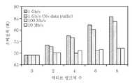
도 1은 Cisco의 Catalyst 2970 스위치모델에서 각 포트의 전송속도, 데이터 유무 따른 소비전력의 변화를 측정한 것이다.Figure 1 shows the change in power consumption of each port in Cisco Catalyst 2970 switch model according to the transmission speed and data.
도 1을 참조하면, Gigabit Ethernet NIC을 10Mb/s, 100Mb/s로 동작시키는 경우 1Gb/s 동작속도에 비해 포트당 각 1.5W의 전력소모를 절감시킬 수 있다. 종래의 네트워크 스위치는 이러한 동작속도에 따른 전력절감 효과를 반영하지 않고 단순히 End-Device의 지원속도를 기준으로 Auto-negociation 알고리즘에 따라 최대지원 속도로 링크 전송속도를 설정하게 된다. 또한, 데이터 전송이 발생하지 않는 구간에서도 정상 동작모드를 유지함으로써, 스위치에서 소비되는 전력이 변화없이 거의 일정한 수준을 유지하게 된다.Referring to FIG. 1, when the Gigabit Ethernet NIC is operated at 10Mb / s and 100Mb / s, power consumption of 1.5W per port can be reduced compared to 1Gb / s operating speed. The conventional network switch does not reflect the power saving effect according to the operation speed, and simply sets the link transmission speed at the maximum support speed according to the auto-negociation algorithm based on the support speed of the end-device. In addition, by maintaining a normal operation mode even in a period where no data transmission occurs, the power consumed by the switch is maintained almost constant level without change.
종래의 네트워크 스위치의 전력절감 연구로는 1Gb/s, 10Gb/s 이더넷 칩셋 자체의 소비전력을 절감하기 위한 PHY/MAC 계층 Energy 절감기술이 IEEE 802.3az Task Group과 Energy Efficient Ethernet Alliance를 중심으로 연구되고 있다.The power saving research of the conventional network switch includes the PHY / MAC layer energy saving technology for reducing the power consumption of the 1Gb / s, 10Gb / s Ethernet chipset itself, based on the IEEE 802.3az Task Group and the Energy Efficient Ethernet Alliance. have.
또한 데이터의 전송량에 따른 PHY 계층의 동적인 전송속도 변화를 통한 소비전력 절감을 달성하고자 하는 ALR(Adaptive Link Rate) MAC 계층 통신 프로토콜 기술과 비테스(Vitesse)사의 액티PHY(ActiPHY) 칩셋, D-Link의 Green Ethernet Switch 등의 시제품이 소비전력 절감형 스위치 제품으로 개발되고 있다.In addition, ALR (Adaptive Link Rate) MAC layer communication protocol technology, Vitesse's ActiPHY chipset, D-Link, which aims to reduce power consumption by changing the dynamic transmission speed of the PHY layer according to the data transmission amount Prototypes such as Green Ethernet Switch are being developed as power-saving switch products.
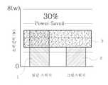
도 2a는 D-Link사의 그린 이더넷 스위치와 종래의 일반 스위치의 전력절감 효율을 비교한 그래프이고, 도 2b는 그린 이더넷 스위치의 개략적인 구성도이다.Figure 2a is a graph comparing the power saving efficiency of the D-Link Green Ethernet switch and the conventional general switch, Figure 2b is a schematic configuration diagram of the green Ethernet switch.
도 2a 내지 도2b를 참조하면 그린 스위치(2,4)가 일반 스위치(1)에 비하여 30% 정도의 전력을 절감시킬 수 있다. 그린 스위치는 다음과 같은 스위치 전력절감 방식을 사용한다.2A to 2B, the
첫째, WAN, LAN 포트에 연결되어 있는 이더넷 링크의 UP/DOWN 상태를 모니터링하고, DOWN 상태인 경우, 연관된 이더넷 포트의 상태를 IDLE 상태로 전이시킨다.First, it monitors the UP / DOWN status of Ethernet links connected to WAN and LAN ports. In the case of DOWN status, it transfers the status of the associated Ethernet port to IDLE status.
둘째, 각 유선 포트에 연결된 링크 케이블의 길이를 자동 측정하여, 측정 길이에 따른 이더넷 송신전력을 조절하여 소비전력을 절감한다.Second, by automatically measuring the length of the link cable connected to each wired port, by controlling the Ethernet transmit power according to the measurement length to reduce the power consumption.
그러나 상기와 같은 종래의 네트워크 스위치의 소비전력 절감기술들은 PHY 또는 MAC Layer 등에서와 같이 Connection-less만을 고려한 방법으로서, 스위치 내부에 구성된 내부 네트워크(LAN)에 위치하는 네트워크 기기들 중 항상 네트워크 연결을 유지해야 하는 서버 또는 어플리케이션 기기들에 대한 고려가 부족하고, 이와 같은 문제점으로 인해, Connection-oriented 통신계층에서는 연결 재설정 등의 네트워크 연결지연이 추가로 발생하게 된다.However, the power consumption reduction techniques of the above-described conventional network switch are a method considering only connectionless as in PHY or MAC Layer, and always maintain a network connection among network devices located in an internal network (LAN) configured inside the switch. There is a lack of consideration of servers or application devices that must be performed. As a result of this problem, network connection delays such as connection reestablishment occur additionally in the connection-oriented communication layer.
또한, 단순히 이더넷 링크의 속도를 조절하거나 이더넷 포트의 상태를 Idle 상태로 전이시키더라도 네트워크 스위치의 메인 시스템 자체는 항상 정상모드로 동작하기 때문에 최대 전력 절감율이 20% 미만에 불과하다.In addition, even if you simply adjust the speed of the Ethernet link or transition the state of the Ethernet port to Idle, the network switch's main system always operates in normal mode, resulting in a maximum power savings of less than 20%.
또한, 네트워크 트래픽의 특성상, 주기적으로 전송되는 알람(Alarm), 공지(Notify), 확인(Acknowledgement) 등 응답을 하지 않아도 네트워크 연결에 영향을 미치지 않는 더미 데이터(Dummy Data)를 전송함에 있어서 발생하는 네트워크 스위치의 오버헤드가 크다.In addition, due to the characteristics of network traffic, a network that occurs in transmitting dummy data that does not affect the network connection even without a response such as an alarm, notification, acknowledgment, etc., transmitted periodically The overhead of the switch is large.
본 발명의 목적은 대기모드 상태에서도 네트워크의 특성을 반영한 Connection-oriented 기반의 초절전 네트워크 스위치 전력관리 방법을 제공하는 것이다.An object of the present invention is to provide a power-saving method of connection-oriented based ultra-low power network switch reflecting network characteristics even in a standby mode.
본 발명의 다른 목적은 대기모드 상태에서도 네트워크의 특성을 반영한 Connection-oriented 기반의 초절전 네트워크 스위치 전력관리 장치를 제공하는 것이다.Another object of the present invention is to provide a power-saving device for a connection-oriented based hibernation network switch reflecting the characteristics of a network even in a standby mode.
본 발명의 목적은 이상에서 언급한 목적으로 제한되지 않으며, 언급되지 않은 또 다른 목적들은 아래의 기재로부터 당업자에게 명확하게 이해될 수 있을 것이다.The object of the present invention is not limited to the above-mentioned object, and other objects that are not mentioned will be clearly understood by those skilled in the art from the following description.
전술한 목적을 달성하기 위한 본 발명의 일면에 따른 네트워크 스위치 전력관리 방법은 네트워크 사용량을 모니터링 하는 단계와 상기 네트워크 사용량에 따라 네트워크 스위치를 정상모드와 대기모드로 구분하고, 네트워크 인터페이스 카드(NIC)를 정상모드 처리부 또는 대기모드 처리부로 스위칭하는 단계와 상기 네트워크 스위치가 대기모드인 경우, 상기 대기모드 처리부의 저전력 모듈을 통해 네트워크 연결을 유지하는 단계를 포함한다.Network switch power management method according to an aspect of the present invention for achieving the above object is to monitor the network usage and the network switch in the normal mode and standby mode according to the network usage, and the network interface card (NIC) Switching to a normal mode processing unit or a standby mode processing unit; and maintaining the network connection through the low power module of the standby mode processing unit when the network switch is in the standby mode.
본 발명의 다른 면에 따른 네트워크 스위치 전력관리 방법은 FPGA의 공유메모리에 저장된 네트워크 스위치의 네트워크 구성 및 상기 네트워크 스위치가 관리 하는 디바이스의 IP 풀(Pool)을 읽어서 NIC의 구성을 재설정하고, 상기 MCU가 관리하는 IP 풀을 구성하는 단계와 상기 재설정된 NIC의 구성과 상기 MCU가 관리하는 IP 풀을 이용하여 상기 대기모드 기간동안 네트워크 프락싱을 수행하는 단계를 포함한다.Network switch power management method according to another aspect of the present invention is to read the network configuration of the network switch stored in the shared memory of the FPGA and the IP pool of the device managed by the network switch to reset the configuration of the NIC, the MCU Configuring the IP pool to be managed, and performing network proxying during the standby mode using the reset NIC configuration and the IP pool managed by the MCU.
상기 네트워크 전력관리 방법은 네트워크 구성을 상기 공유메모리에 저장하기 전에 정상모드 처리부의 메인 CPU에 저장하는 단계와 상기 네트워크 스위치가 관리하는 디바이스의 IP 풀을 상기 정상모드 처리부의 메인 CPU에 저장하는 단계와 상기 메인 CPU에 저장된 상기 네트워크 구성 및 상기 IP 풀을 상기 공유메모리에 기록하는 단계를 더 포함한다.The network power management method includes storing a network configuration in a main CPU of a normal mode processing unit before storing the network configuration in the shared memory, and storing an IP pool of a device managed by the network switch in the main CPU of the normal mode processing unit; And recording the network configuration and the IP pool stored in the main CPU in the shared memory.
본 발명의 또 다른 면에 따른 네트워크 스위치 전력관리 방법은 네트워크 스위치가 대기모드 상태에서 수신된 패킷이 웨이크업패킷인 경우, 대기모드를 홀딩시키고, 상기 네트워크 스위치를 정상모드로 웨이크업 시키는 단계와 상기 웨이크업에 걸리는 지연시간(Tdelay)동안 상기 네트워크 스위치로 수신되는 패킷을 인터럽트하고, 상기 지연시간 후에 상기 인터럽트를 정상모드 처리부로 포워딩하는 단계를 포함한다.According to another aspect of the present invention, there is provided a network switch power management method, when a received packet is a wake-up packet when the network switch is in the standby mode, holding the standby mode and waking up the network switch to the normal mode. Interrupting a packet received by the network switch during a delay time (Tdelay ) for the wake-up, and forwarding the interrupt to the normal mode processing unit after the delay time.
본 발명의 또 다른 면에 따른 네트워크 스위치의 전력관리 장치는 네트워크 스위치에 연결된 로컬네트워크의 네트워크 사용량을 모니터링하고, 상기 네트워크 사용량에 따라 NIC를 정상모드 처리부 또는 대기모드 처리부로 스위칭하는 FPGA와 상기 정상모드인 경우, 상기 로컬 네트워크의 네트워크 사용대역폭을 임계치와 비 교하여 핸드쉐이크 하는 정상모드 처리부와 상기 대기모드인 경우, 저전력 모듈을 통해 네트워크 연결을 유지하는 대기모드 처리부를 포함한다.An apparatus for managing power of a network switch according to another aspect of the present invention monitors network usage of a local network connected to a network switch and switches the NIC to a normal mode processing unit or a standby mode processing unit according to the network usage and the normal mode. In the case of the standby mode, the normal mode processing unit for shaking hands by comparing the network bandwidth of the local network, and in the standby mode, the standby mode processing unit for maintaining a network connection through the low power module.
상기 FPGA는 네트워크 사용량을 측정하는 트래픽 모니터링부와 NIC의 MAC 주소와 IP 주소를 포함하는 네트워크 구성과 상기 네트워크 스위치에 의해 관리되는 디바이스의 IP 풀을 저장하는 공유메모리부와 상기 대기모드에서 정상모드로 전환될 때 소정의 지연시간 동안 수신된 패킷의 인터럽트를 홀딩시키는 인터럽트 홀딩부를 포함한다.The FPGA includes a traffic monitoring unit for measuring network usage, a network configuration including a MAC address and an IP address of a NIC, a shared memory unit for storing an IP pool of a device managed by the network switch, and the standby mode in a normal mode. And an interrupt holding unit for holding an interrupt of a received packet for a predetermined delay time when switching.
기타 실시예들의 구체적인 사항들은 상세한 설명 및 도면들에 포함되어 있다.Specific details of other embodiments are included in the detailed description and the drawings.
본 발명에 따르면, Connection-oriented를 고려하여 네트워크 스위치의 전력을 관리하므로 대기모드 상태에서도 네트워크 연결을 보장할 수 있다.According to the present invention, since the power of the network switch is managed in consideration of connection-oriented, the network connection can be guaranteed even in the standby mode.
또한, 일반적인 가정에서 인터넷 사용시간이 8시간 내외임을 가정해 볼 때 나머지 시간에 발생할 수 있는 전력의 손실을 본 발명에 따른 대기모드 상태에서의 전력 절감 기술을 이용함으로써, 홈 네트워크의 전력절감 효율을 향상시킬 수 있다.In addition, assuming that Internet use time is about 8 hours in a typical home, power saving efficiency of a home network can be improved by using power saving technology in a standby mode according to the present invention. Can be improved.
또한, 네트워크 트래픽의 사용량에 따라 유동적으로 네트워크 속도를 조절함으로써 전체 전력 소모량을 조절할 수 있으므로 네트워크 스위치의 소비전력을 효율적으로 관리할 수 있다.In addition, it is possible to efficiently manage the power consumption of the network switch because the overall power consumption can be adjusted by flexibly adjusting the network speed according to the usage of network traffic.
본 발명의 이점 및 특징, 그리고 그것들을 달성하는 방법은 첨부되는 도면과 함께 상세하게 후술되어 있는 실시예들을 참조하면 명확해질 것이다. 그러나 본 발명은 이하에서 개시되는 실시예들에 한정되는 것이 아니라, 서로 다른 다양한 형태로 구현될 것이며, 단지 본 실시예들은 본 발명의 개시가 완전하도록 하며, 본 발명이 속하는 기술분야에서 통상의 지식을 가진 자에게 발명의 범주를 완전하게 알려주기 위해 제공되는 것이며, 본 발명은 청구항의 범주에 의해 정의될 뿐이다.Advantages and features of the present invention and methods for achieving them will be apparent with reference to the embodiments described below in detail with the accompanying drawings. However, the present invention is not limited to the embodiments disclosed below, but may be embodied in various different forms, and only the present embodiments make the disclosure of the present invention complete, and those of ordinary skill in the art to which the present invention belongs. It is provided to fully inform the person having the scope of the invention, which is defined only by the scope of the claims.
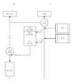
도 3은 본 발명의 일 실시예에 따른 네트워크 스위치의 구성도이다.3 is a configuration diagram of a network switch according to an embodiment of the present invention.
도 3을 참조하면, 일 실시예에 따른 네트워크 스위치는 i개의 네트워크 인터페이스 카드(10_1, 10_2,…,10_i)(이하 'NIC'라 함)를 포함하는 이더넷 포트(10), 이더넷 포트(10)와 연결되어 로컬 네트워크 사용량을 모니터링하는 FPGA(20), 상기 로컬 네트워크 사용량에 따라서 네트워크 스위치가 정상모드 또는 대기모드로 전환되고, 정상모드일 때는 NIC(10_1, 10_2,…,10_i)이 메인 CPU(31)에 연결되고, 대기모드일 때는 MCU(Micro Controller Unit)(41)에 연결된다.Referring to FIG. 3, a network switch according to an embodiment includes an
이더넷 포트(10)는 다수의 NIC(10_1, 10_2,…,10_i)를 포함하고 있으며, NIC을 통해서 네트워크의 타 호스트와의 데이터 교환이 이루어진다. 다만, 네트워크 스위치는 허브와는 달리 각 호스트에서 주고받는 데이터를 다른 모든 호스트에 전송하는 것이 아니라, 데이터를 필요로 하는 호스트에만 전송하는 방식이다.The Ethernet
FPGA(20)는 이더넷 포트(10)와 연결되어 있으며, 네트워크 트래픽량을 항상 모니터링 하는 트래픽 모니터링부(21)를 포함한다.The
트래픽 모니터링부(21)는 NIC(10_1, 10_2,…,10_i)을 통한 트래픽량이 미미 하거나 없는 경우에는 네트워크 스위치를 대기모드로 전환시킨다. 네트워크 스위치가 대기모드로 전환되면 MCU(41)와 연결된다.The
한편, FPGA(20)는 네트워크 트래픽량이 소정의 기준량을 초과하는 경우에는 네트워크 스위치를 정상모드로 전환시킨다. 네트워크 스위치가 정상모드로 전환되면 네트워크 인터페이스는 메인 CPU(31)와 연결된다.On the other hand, the
즉, 네트워크 내의 트래픽량이 미미하거나 없는 경우에도 종래의 네트워크 스위치에서는 항상 시스템을 정상모드로 유지하는 방식을 택하고 있어 전력관리에 문제점이 있었으나, 본 발명에서는 네트워크 내의 트래픽량에 따라서 네트워크 스위치의 동작모드를 정상모드 또는 대기모드로 전환하여 전력을 관리한다.In other words, even if the traffic in the network is small or no, the conventional network switch always has a system to maintain the normal mode, there is a problem in power management, in the present invention, the operation mode of the network switch according to the amount of traffic in the network Power is managed by switching to normal mode or standby mode.
FPGA(20)를 통해 NIC(10_1, 10_2,…,10_i)은 메인 CPU(31)와 MCU(41)에 동시에 연결되어 있으며 정상모드에서는 메인 CPU(31)에 엑세스되고, 대기모드에서는 MCU(41)에 엑세스 되도록 프로그래밍 되어있다.The NICs 10_1, 10_2,..., 10_i are simultaneously connected to the
MCU(41는) 저전력 모듈로서, 대기모드 상태에서도 Connection-oriented를 구현할 수 있도록 한다. 예컨대, ATmega128 등이 MCU(41)로 사용될 수 있다.The MCU 41 is a low-power module that enables connection-oriented implementation even in a standby mode. For example, ATmega128 or the like can be used as the MCU 41.
이하에서는 도 4 내지 도 5b을 참조하여 네트워크 내부의 트래픽량에 따라서 정상모드에서의 전력절감 기술과 대기모드에서의 전력절감 기술을 설명한다.Hereinafter, the power saving technique in the normal mode and the power saving technique in the standby mode will be described with reference to FIGS. 4 through 5B.
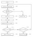
도 4는 본 발명의 일 실시예에 따른 정상모드에서의 전력절감방법을 나타낸 순서도이고, 도 5a은 본 발명의 일 실시예에 따른 정상모드와 대기모드에서의 네트워크 스위치의 전력절감 방법을 나타내는 순서도이고, 도 5b는 도 5a의 대기모드에서의 네트워크 속도를 조절함으로써 네트워크 스위치의 전체 전력소모량을 조절하 는 방법을 나타낸 순서도이다.4 is a flowchart illustrating a power saving method in a normal mode according to an embodiment of the present invention, Figure 5a is a flowchart showing a power saving method of the network switch in the normal mode and standby mode according to an embodiment of the present invention. 5B is a flowchart illustrating a method of controlling the total power consumption of the network switch by adjusting the network speed in the standby mode of FIG. 5A.
정상모드에서 본 발명의 일 실시예에 따른 네트워크 스위치는 네트워크의 트래픽 사용량에 따라 유동적으로 이더넷 링크의 속도를 조절함으로써 전체 전력 소모량을 조절한다.In the normal mode, the network switch according to an embodiment of the present invention adjusts the total power consumption by flexibly adjusting the speed of the Ethernet link according to the traffic usage of the network.
도 4를 참조하면, 네트워크 스위치는 평상시에 네트워크 스위치의 트래픽량을 모니터링 한다(S201). 링크속도가 느리면(S203) 버퍼의 길이와 미리 설정된 최대임계치와 비교하여 버퍼의 길이가 최대임계치 이상이면(S205) 링크 속도를 더 높일 수 있으므로 링크속도를 높이기 위한 핸드쉐이크를 수행한다(S206).Referring to FIG. 4, the network switch normally monitors the traffic volume of the network switch (S201). If the link speed is slow (S203), if the length of the buffer is greater than or equal to the maximum threshold value (S205), the link speed may be further increased (S205). Therefore, a handshake to increase the link speed is performed (S206).
링크 속도가 빠르면(S207) 버퍼의 길이와 최소 임계치를 비교하여, 버퍼의 길이가 최소 임계치 이상이면(S209) 측정된 사용대역폭과 상기 최소 임계치를 비교한다. 사용대역폭이 최소 임계치보다 작으면 링크에 트래픽 량이 적은 것으로 볼 수 있고, 따라서 링크속도를 낮추기 위한 핸드쉐이크를 수행한다(S213).If the link speed is high (S207), the length of the buffer is compared with the minimum threshold, and if the length of the buffer is greater than the minimum threshold (S209), the measured use bandwidth is compared with the minimum threshold. If the bandwidth used is less than the minimum threshold, it may be considered that the amount of traffic on the link is small, and thus, a handshake to lower the link speed is performed (S213).
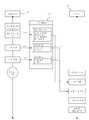
도 5a를 참조하면, 네트워크 스위치가 정상모드 일 때(S301), FPGA(20)의 트래픽 모니터링부(21)에서 네트워크 사용량을 모니터링하여(S303), 네트워크 사용량이 미미하거나 없는 경우(S305)에는 대기모드로 진입하고(S401), 그렇지 않은 경우에는 정상모드로 유지한다(S307).Referring to FIG. 5A, when the network switch is in the normal mode (S301), the
본 발명에서는 정상모드에서 네트워크에 사용되는 대역폭을 측정하여(S309) 네트워크 속도를 조절하는 방법(S315, S319)을 통해 대기모드에서 뿐만 아니라 정상모드에서도 네트워크 스위치의 소비전력을 절감시킬 수 있다.In the present invention, the power consumption of the network switch can be reduced in the normal mode as well as in the standby mode through the method of adjusting the network speed by measuring the bandwidth used for the network in the normal mode (S309) (S315, S319).
네트워크 스위치는 각 로컬 이더넷 포트별로 사용대역폭을 측정(S309)하고, 미리 설정된 대역폭의 최대 임계치 qHIGH, 최소 임계치 qLOW와 비교한다(S309).The network switch measures the used bandwidth for each local Ethernet port (S309), and compares it with the maximum threshold qHIGH and the minimum threshold qLOW of the preset bandwidth (S309).
비교결과, 사용되는 네트워크 대역폭이 최대 임계치 qHIGH 이상인 경우(S313) 100Mbps 이상의 고속의 속도로 동작하도록 네트워크 속도를 높인다(S315). 이 경우는 버퍼(미도시)의 길이가 최대 임계치 qHIGH 보다 길기 때문에 고속의 링크 레이트(high link rate)를 위한 핸드쉐이크를 수행한다.As a result of the comparison, when the network bandwidth used is greater than or equal to the maximum threshold qHIGH (S313), the network speed is increased to operate at a high speed of 100Mbps or more (S315). In this case, since the length of the buffer (not shown) is longer than the maximum threshold qHIGH, a handshake for a high link rate is performed.
한편, 사용되는 네트워크 대역폭이 최소 임계치 qLOW 이하인 경우(S317)에는 예컨대, 10Mbps~100Mbps의 속도로 동작하도록 네트워크 속도를 낮춘다(S319). 이 경우는 상기 버퍼의 길이가 최소 임계치 qLOW 보다 짧기 때문에 네트워크 속도를 낮추기 위한 위한 핸드쉐이크를 수행한다.On the other hand, if the network bandwidth used is less than the minimum threshold qLOW (S317), for example, the network speed is lowered to operate at a speed of 10Mbps ~ 100Mbps (S319). In this case, since the length of the buffer is shorter than the minimum threshold qLOW, a handshake for lowering the network speed is performed.
이더넷 링크의 경우 로컬 네트워크의 한 포트당 전력소모량이 1Gbps의 경우 1W 이상을, 10Mbps의 경우는 300mW 정도의 전력을 소모한다. 즉, 네트워크의 속도차에 따라서 소비되는 전력량의 차가 크기 때문에 본 발명에서와 같이 네트워크의 사용량에 따라서 자동적으로 네트워크 스위치의 속도를 조정할 필요가 있는 것이다. 특히, 지속적으로 네트워크 트래픽을 많이 사용하지 않는 일반적인 홈 네트워크 환경에서는 본 발명에 따른 네트워크 트래픽량에 따른 전력 소모량 조절방법은 매우 유효한 소비전력 절감방법이 될 수 있다.The Ethernet link consumes more than 1W of power per port on the local network and 300mW of power for 10Mbps. That is, since the difference in the amount of power consumed according to the speed difference of the network is large, it is necessary to automatically adjust the speed of the network switch according to the usage of the network as in the present invention. In particular, in a general home network environment that does not continuously use a lot of network traffic, the method of controlling power consumption according to the amount of network traffic according to the present invention may be a very effective method of reducing power consumption.
FPGA(20)에서 네트워크 사용량을 측정한 결과 네트워크 사용량이 미미하거나 없는 경우에는 대기모드로 진입한다(S401). 대기모드에서, 네트워크 스위치의 소비전력절감 방법을 도 5b를 통해 설명한다.As a result of measuring the network usage in the
네트워크 스위치가 대기모드로 진입하면(S401), NIC(10_1, 10_2,…,10_i)는 FPGA(20)를 통해 대기모드를 제어하는 저전력 MCU(41)와 연결됨으로써, 기존에 네트워크에 연결된 PC, PDA 등의 클라이언트는 끊김없이 네트워크와의 연결을 유지할 수 있다. 즉, 네트워크 스위치가 대기모드에 있더라도 로컬 네트워크는 모든 동작 가능한 상태로 데이터를 수신한다.When the network switch enters the standby mode (S401), the NICs 10_1, 10_2,..., 10_i are connected to the
대기모드에서 수신된 데이터는 MCU(41)에서 송수신 주소가 분석되어(S403) 상기 데이터가 네트워크 스위치 내부에 속하는 로컬 네트워크의 디바이스인지를 구분한다(S405).The data received in the standby mode is analyzed by the
상기 주소가 네트워크 스위치 내부에 속하는 로컬 네트워크의 디바이스인 경우, 수신한 패킷 데이터를 분석한다(S407). 패킷 데이터를 분석하는 이유는 대기모드는 저전력 모드로서, 저전력 MCU(41)가 처리할 수 있는 패킷인지, 혹은 상기 MCU(41)가 처리할 필요가 없는 패킷 인지를 구분함으로써, 대기모드가 지속되는 시간을 연장할 수 있고, 이로 인해 네트워크 스위치의 전력절감 효율을 높일 수 있기 때문이다.If the address is a device of the local network belonging to the network switch, the received packet data is analyzed (S407). The reason for analyzing the packet data is that the standby mode is a low power mode, in which the standby mode is continued by distinguishing whether the packet can be processed by the
패킷 데이터를 분석하기 위해서 네트워크 스위치는 NIC(10_1, 10_2,…,10_i)을 통해 수신되는 패킷 데이터를 종류별로 구분한다. 예컨대, 패킷 데이터를 더미 패킷(Dummy Packet), 프락싱패킷(Proxying Packet), 웨이크업패킷(Wake-up Packet)으로 구분할 수 있다.In order to analyze the packet data, the network switch classifies the packet data received through the NICs 10_1, 10_2,..., 10_i by type. For example, the packet data may be classified into a dummy packet, a proxying packet, and a wake-up packet.
더미패킷은 주기적으로 전송되는 넷바이어스 데이터그램(NetBIOS Datagram)이나 라우팅 헬로우(hellow) 패킷과 같이 응답을 하지 않아도 무방한 Discard 형태의 패킷으로, 네트워크 스위치가 대기모드로 진입했을 때 저전력 MCU(41)에서 네트 워크 트래픽을 분석하여 중요하지 않은 패킷 데이터에 대한 프락싱을 수행함으로써 대기모드 진입시간을 연장한다.The dummy packet is a Discard type packet that does not need to respond, such as a NetBIOS Datagram or a Routing Hello packet, which is transmitted periodically, and a low power MCU (41) when the network switch enters a standby mode. The network enters the standby mode entry time by analyzing network traffic and performing proxying on the insignificant packet data.
프락싱패킷은 ARP(Address Resolution Protocol) Request나, DHCP(Daynamic Host Configuration Protocol) 메시지 패킷과 같이 간단한 형태의 응답을 요하는 패킷으로 대기모드 상태에서 미리 프로그래밍된 MCU Code를 이용하여 응답을 만들 수 있는 프락싱 가능한 패킷이다.The proxying packet is a packet that requires a simple response, such as an ARP (Address Resolution Protocol) request or a DHCP (Daynamic Host Configuration Protocol) message packet, and can make a response using preprogrammed MCU code in the standby mode. This is a packet that can be proxied.
웨이크업패킷은 전송 제어 프로토콜(TCP;Transmission Control Protocol), 사용자 데이터그램 프로토콜(UDP;User Datagram Protocol), 메신저 데이터(Messenger Data) 등을 포함하나 이에 제한되지 않는 각종 유형의 메지시들을 포함한다. 웨이크업패킷은 저전력 모드에서는 처리할 수 없고 정상모드에서 처리 가능한 복잡한 형태의 패킷이다.The wakeup packet includes various types of messages including, but not limited to, Transmission Control Protocol (TCP), User Datagram Protocol (UDP), Messenger Data, and the like. A wakeup packet is a complex packet that cannot be processed in low power mode but can be processed in normal mode.
패킷 데이터를 분석한 결과, 상기 데이터가 더미패킷인 경우에는 네트워크 스위치는 해당 패킷을 처리하지 않고 무시한다.As a result of analyzing the packet data, if the data is a dummy packet, the network switch does not process the packet and ignores it.
패킷 데이터를 분석한 결과 프락싱 패킷인 경우에는 MCU(41)자체에서 ARP Request등에 응답하여 프락싱을 수행한다(S411).As a result of analyzing the packet data, if the packet is a proxying packet, the
패킷 데이터를 분석한 결과 패킷 데이터가 웨이크업패킷인 경우, MCU(41)는 일단, 저전력 모드의 MCU(41)시스템을 홀딩(holding) 시킨다.As a result of analyzing the packet data, when the packet data is a wake-up packet, the
다만, 정상모드로 진입(S415)되기 전에는 NIC(10_1, 10_2,…,10_i)를 통해 수신되는 데이터를 받아서 FPGA(20)의 인터럽트 홀딩부(23)를 통해 인터럽트 홀딩(Interrupt Holding)시킨다. 대기모드에서 정상모드로의 전환이 완료되면 상기 대기모드서 홀딩시킨 데이터를 메인 CPU(31)에서 처리하게 된다.However, before entering the normal mode (S415), the data received through the NICs 10_1, 10_2,..., 10_i is received and interrupted through the interrupt holding
한편, 상기 FPGA(20)의 인터럽트 홀딩부(23)를 통해 인터럽트 홀딩(Interrupt Holding)되는 과정은 도 6c에서 후술한다.Meanwhile, the process of interrupt holding through the interrupt holding
도 6a는 본 발명의 일 실시예에 따른 대기모드 기간 유지를 위한 네트워크 프락싱을 나타내는 구성도이고, 도 6b는 도 6a에 따른 공유메모리부를 통한 네트워크 프락싱을 위한 네트워크 스위치의 일부 구성도이고, 도 6c는 도 6a의 정상모드와 대기모드에서의 네트워크 스위치 동작을 나타내는 순서도이다.6A is a block diagram illustrating network proxying for maintaining a standby mode period according to an embodiment of the present invention, and FIG. 6B is a block diagram of a network switch for network proxying through a shared memory unit according to FIG. 6A. FIG. 6C is a flowchart illustrating a network switch operation in a normal mode and a standby mode of FIG. 6A.
도 6a 내지 도 6c를 참조하면, 네트워크 스위치가 정상모드일 때 메인 CPU(31)는 네트워크 스위치가 대기모드에서 정상적으로 동작할 수 있도록 하기 위하여 네트워크 스위치 자신의 네트워크 구성정보와 네트워크 스위치에 의해서 관리되어야 할 디바이스의 리스트를 FPGA(20)의 공유메모리부(Shared Memory)(22)에 저장시킨다. 상기 공유메모리부(22)에 저장된 정보는 네트워크 스위치가 대기모드로 전환되면 MCU(41)에 의해 사용된다.6A to 6C, when the network switch is in the normal mode, the
여기서 네트워크 스위치 자신의 네트워크 구성정보는 NIC의 MAC 주소와 IP 주소를 의미한다.The network configuration information of the network switch itself refers to the MAC address and IP address of the NIC.
도 6b에 도시된 공유메모리부(22)는 FPGA(20)에 포함되어 있으며, 대기모드/정상모드 전환을 위해 메인 CPU(31)를 통해 저장받는 정보를 MCU(41)로 전달하는 기능을 한다.The shared
먼저, 네트워크 스위치가 정상모드에서 동작할 때 시스템을 초기화 하고(S701), 네트워크 스위치 자신의 WAN, LAN 칩셋의 구성정보 즉, 각각의 NIC의 IP 주소와, MAC 주소를 저장하고(S703) 이를 FPGA에 포함된 공유메모리부(22)에 저장시킨다.First, when the network switch operates in the normal mode, the system is initialized (S701), the network switch's own WAN and LAN chipset configuration information, that is, the IP address and the MAC address of each NIC (S703) is stored and the FPGA is stored. It is stored in the shared
또한, 현재 네트워크 스위치가 관리하는 디바이스들의 IP 주소 풀을 구성하여 저장하고(S705), 이를 상기 공유메모리부(22)에 저장한다.In addition, an IP address pool of devices currently managed by the network switch is configured and stored (S705), and stored in the shared
네트워크 스위치가 대기모드로 전환하면 MCU(41)는 대기모드에서 데이터를 처리하기 위하여 시스템을 초기화하고, MCU(41)는 상기 공유메모리부(22)에 저장된 네트워크 구성과 네트워크 스위치가 관리할 IP 풀의 구성을 이용하여 MCU(41) 자신의 네트워크 칩셋을 재설정(S711)하고, MCU(41) 자신이 관리할 IP 풀의 리스트를 구성한다(S713).When the network switch enters the standby mode, the
그 후, MCU(41)는 데이터 패킷을 수신하고(S715) 트래픽을 분석하여(S717) 상기 수신한 패킷이 자신이 관리할 IP 풀의 구성에 포함되는지 확인하고(S719), 포함되면 패킷을 처리한다.Thereafter, the
또한, 패킷이 MCU(41)가 프락싱 가능한 패킷이면 응답 패킷을 생성하여 전송하고(S723), 상기 패킷이 웨이크업패킷이면 후술하는 인터럽트 홀딩방법을 통해 시스템을 홀딩시키고 정상모드로의 전환을 준비한다.In addition, if the packet is a packet capable of being proxied by the
한편, 상기 수신한 패킷이 상기 IP 풀에 포함되지 않으면 패킷처리를 수행하지 않고 무시한다.On the other hand, if the received packet is not included in the IP pool, it is ignored without performing packet processing.
도 7a은 본 발명의 일 실시예에 따른 대기모드에서 웨이크업 패킷이 수신되는 경우 인터럽트 홀딩(Interrupt Holding)을 나타내는 구성이고, 도 7b는 도 7a의 인터럽트 홀딩과정을 나타내는 순서도이다.FIG. 7A is a diagram illustrating interrupt holding when a wakeup packet is received in a standby mode according to an embodiment of the present invention, and FIG. 7B is a flowchart illustrating the interrupt holding process of FIG. 7A.
도 7a 내지 도 7b를 참조하면, 대기모드에서 수신하는 패킷이 MCU(41)가 처리하지 못하는 웨이크업패킷인 경우(S721), MCU(41)시스템은 홀딩되고(S725), 네트워크 스위치는 정상모드로 전환되어야 한다.7A to 7B, when the packet received in the standby mode is a wake-up packet that the
다만, 네트워크 스위치가 대기모드에서 정상모드로 전환되는데 걸리는 지연시간 Tdelay 동안의 수신패킷의 처리가 문제된다. 상기 지연시간 Tdelay 동안 수신한 패킷을 처리하기 위한 단계가 없다면 패킷의 손실이 생길 수 있기 때문이다.However, there is a problem in the processing of the reception packet during the delay time Tdelay required for the network switch to switch from the standby mode to the normal mode. This is because if there is no step for processing the received packet during the delay time Tdelay , packet loss may occur.
MCU(41)가 지연시간 Tdelay 동안 패킷을 수신하여(S727) 도 6b에 도시한 FPGA(20)의 인터럽트 홀딩부(23)에서 상기 수신된 패킷을 인터럽트 홀딩시킨다(S729). 이 때 지연시간 Tdelay는 네트워크 스위치가 대기모드에서 정상모드로 전환되는 시간 T1과 네트워크 칩셋이 활성화되는 데 걸리는 시간 T2를 포함한다. 즉, 지연시간 Tdelay= T1+T2 이다.The
지연시간 Tdelay가 지나면 네트워크 스위치는 정상모드로 전환되고(S731), 인터럽트 홀딩부(23)는 메인 CPU(31)에 인터럽트를 전달한다(S733). 인터럽트 홀딩부(23)로부터 인터럽트를 전달받은 메인 CPU(31)는 상기 지연시간 Tdelay동안 수신된 웨이크업 패킷을 처리한다(S735).After the delay time Tdelay has elapsed, the network switch is switched to the normal mode (S731), and the interrupt holding
즉, 대기모드에서는 네트워크 스위치가 저전력 모드로 동작되지만 MCU(41)를 통해 네트워크가 Connection-Oriented 상태를 유지한다. 이는 예컨대, 인터넷을 통하여 멀티미디어 콘텐츠를 다운로드 받은 상태에서 장시간 사용하는 경우, 실제로 네트워크 트래픽량은 없지만 상기 멀티 미디어 콘텐츠를 이용하기 위하여 네트워크 스위치도 정상모드로 작동되는 종래의 네트워크 스위치 구조와는 달리, 컴퓨터를 통하여 상기 멀티미디어 콘텐츠를 장시간 이용하면서 네트워크 스위치는 대기모드 상태로 전환되어 소비전력을 절감시킬 수 있게 된다.That is, in the standby mode, the network switch operates in the low power mode, but the network maintains the connection-oriented state through the
MCU(41)를 통해 프락싱 패킷을 처리하는 과정과 대기모드에서 수신되는 웨이크업패킷을 처리하기 위한 인터럽트 홀딩 과정을 통해 상기 Connection-Oriented 상태를 유지할 수 있는 것이다. The Connection-Oriented state can be maintained through the process of processing the proxying packet through the
본 발명이 속하는 기술분야의 통상의 지식을 가진 자는 본 발명이 그 기술적 사상이나 필수적인 특징을 변경하지 않고서 다른 구체적인 형태로 실시될 수 있다는 것을 이해할 수 있을 것이다. 예를 들어 본 발명의 네트워크 스위치를 제어하기 위한 방법을 실현하기 위한 프로그램이 기록된 기록매체의 형태 등 다양한 형태로 구현될 수 있다. 그러므로 이상에서 기술한 실시예들은 모든 면에서 예시적인 것이며 한정적이 아닌 것으로 이해해야만 한다. 본 발명의 범위는 상기 상세한 설명보다는 후술하는 특허청구의 범위에 의하여 나타내어지며, 특허청구의 범위의 의미 및 범위 그리고 그 균등 개념으로부터 도출되는 모든 변경 또는 변형된 형태가 본 발명의 범위에 포함되는 것으로 해석되어야 한다.Those skilled in the art will appreciate that the present invention can be embodied in other specific forms without changing the technical spirit or essential features of the present invention. For example, the program for realizing the method for controlling the network switch of the present invention can be implemented in various forms, such as in the form of a recording medium having recorded thereon. It is therefore to be understood that the above-described embodiments are illustrative in all aspects and not restrictive. The scope of the present invention is indicated by the scope of the following claims rather than the detailed description, and all changes or modifications derived from the meaning and scope of the claims and the equivalent concept are included in the scope of the present invention. Should be interpreted.
도 1은 종래기술에 따른 Cisco의 Catalyst 2970 스위치모델을 기준으로 측정한 값이며, 각 포트의 전송속도, 데이터 유무 따른 소비전력의 변화를 측정한 것.Figure 1 is a value measured based on the Cisco Catalyst 2970 switch model according to the prior art, it is a measure of the change in power consumption according to the transmission speed, data presence of each port.
도 2a는 D-Link사의 그린 이더넷 스위치와 종래의 일반 스위치의 전력절감 효율을 비교한 그래프.Figure 2a is a graph comparing the power saving efficiency of the D-Link Green Ethernet switch and a conventional general switch.
도 2b는 종래기술에 따른 그린 이더넷 스위치의 개략적인 구성도.Figure 2b is a schematic diagram of a green Ethernet switch according to the prior art.
도 3은 본 발명의 일 실시예에 따른 네트워크 스위치의 구성도.3 is a block diagram of a network switch according to an embodiment of the present invention.
도 4는 본 발명의 일 실시예에 따른 정상모드에서의 전력절감방법을 나타낸 순서도.4 is a flowchart illustrating a power saving method in a normal mode according to an embodiment of the present invention.
도 5a은 본 발명의 일 실시예에 따른 정상모드와 대기모드에서의 네트워크 스위치의 전력절감 방법을 나타내는 순서도.5A is a flowchart illustrating a power saving method of a network switch in a normal mode and a standby mode according to an embodiment of the present invention.
도 5b는 도 5a의 정상모드에서의 네트워크 속도를 조절함으로써 네트워크 스위치의 전체 전력소모량을 조절하는 방법을 나타낸 순서도.FIG. 5B is a flowchart illustrating a method of controlling the total power consumption of the network switch by adjusting the network speed in the normal mode of FIG. 5A. FIG.
도 6a는 본 발명의 일 실시예에 따른 대기모드 기간 유지를 위한 네트워크 프락싱을 나타내는 구성도.6A is a block diagram illustrating network proxying for maintaining a standby mode period according to an embodiment of the present invention.
도 6b는 도 6a에 따른 공유메모리부를 통한 네트워크 프락싱을 위한 네트워크 스위치의 일부 구성도.FIG. 6B is a partial configuration diagram of a network switch for network proxying through the shared memory unit according to FIG. 6A.
도 6c는 도 6a의 정상모드와 대기모드에서의 네트워크 스위치 동작을 나타내는 순서도.FIG. 6C is a flowchart illustrating network switch operation in a normal mode and a standby mode of FIG. 6A; FIG.
도 7a은 본 발명의 일 실시예에 따른 대기모드에서 Wake-up 패킷이 수신되는 경우 인터럽트 홀딩(Interrupt Holding)을 나타내는 구성.FIG. 7A illustrates an interrupt holding when a wake-up packet is received in a standby mode according to an embodiment of the present invention. FIG.
도 7b는 도 7a의 인터럽트 홀딩과정을 나타내는 순서도.FIG. 7B is a flowchart illustrating an interrupt holding process of FIG. 7A. FIG.
《도면의 주요부분에 대한 부호의 설명》`` Explanation of symbols for main parts of drawings ''
10: 이더넷 포트 10_1,10_2,…10_i: NIC10: Ethernet port 10_1,10_2,... 10_i: NIC
20: FPGA 21: 트래픽 모니터링부20: FPGA 21: traffic monitoring unit
22: 공유 메모리부 23: 인터럽트 홀딩부22: shared memory unit 23: interrupt holding unit
30: 정상모드 처리부 31: 메인 CPU30: normal mode processor 31: main CPU
40: 대기모드 처리부 41: MCU40: standby mode processing unit 41: MCU
Claims (23)
Translated fromKoreanPriority Applications (1)
| Application Number | Priority Date | Filing Date | Title |
|---|---|---|---|
| KR1020090026143AKR101064649B1 (en) | 2009-03-26 | 2009-03-26 | Method and apparatus for network switch power management |
Applications Claiming Priority (1)
| Application Number | Priority Date | Filing Date | Title |
|---|---|---|---|
| KR1020090026143AKR101064649B1 (en) | 2009-03-26 | 2009-03-26 | Method and apparatus for network switch power management |
Related Child Applications (1)
| Application Number | Title | Priority Date | Filing Date |
|---|---|---|---|
| KR1020100132298ADivisionKR101093656B1 (en) | 2010-12-22 | 2010-12-22 | How to reduce standby power and improve energy efficiency of network devices |
Publications (2)
| Publication Number | Publication Date |
|---|---|
| KR20100107842A KR20100107842A (en) | 2010-10-06 |
| KR101064649B1true KR101064649B1 (en) | 2011-09-15 |
Family
ID=43129494
Family Applications (1)
| Application Number | Title | Priority Date | Filing Date |
|---|---|---|---|
| KR1020090026143AExpired - Fee RelatedKR101064649B1 (en) | 2009-03-26 | 2009-03-26 | Method and apparatus for network switch power management |
Country Status (1)
| Country | Link |
|---|---|
| KR (1) | KR101064649B1 (en) |
Families Citing this family (4)
| Publication number | Priority date | Publication date | Assignee | Title |
|---|---|---|---|---|
| WO2016167382A1 (en)* | 2015-04-14 | 2016-10-20 | 가온미디어 주식회사 | Access point device of port mirroring-based low-power control scheme, and low-power control method therefor |
| US20180198704A1 (en)* | 2015-09-25 | 2018-07-12 | Hewlett Packard Enterprise Development Lp | Pre-processing of data packets with network switch application -specific integrated circuit |
| KR101872107B1 (en)* | 2016-09-19 | 2018-06-27 | 전자부품연구원 | Network Standby Mode Operation Method applying a Delayed Transmission Techniques for Power Saving |
| KR101875187B1 (en)* | 2017-08-21 | 2018-07-06 | (주)한드림넷 | Apparatus and method for controlling power-saving of network switch |
Citations (4)
| Publication number | Priority date | Publication date | Assignee | Title |
|---|---|---|---|---|
| JP2004034488A (en) | 2002-07-03 | 2004-02-05 | Canon Inc | Image forming apparatus, power control method, computer-readable storage medium, and program |
| KR20040095163A (en)* | 2003-05-05 | 2004-11-12 | 마이크로소프트 코포레이션 | Method and system for auxiliary processing of information for a computing device |
| KR20060105434A (en)* | 2005-03-29 | 2006-10-11 | 마이크로소프트 코포레이션 | Power Management for the LAN |
| KR20070086545A (en)* | 2004-12-23 | 2007-08-27 | 인텔 코오퍼레이션 | Method and apparatus for adjusting duty cycle to save power in computing systems |
- 2009
- 2009-03-26KRKR1020090026143Apatent/KR101064649B1/ennot_activeExpired - Fee Related
Patent Citations (4)
| Publication number | Priority date | Publication date | Assignee | Title |
|---|---|---|---|---|
| JP2004034488A (en) | 2002-07-03 | 2004-02-05 | Canon Inc | Image forming apparatus, power control method, computer-readable storage medium, and program |
| KR20040095163A (en)* | 2003-05-05 | 2004-11-12 | 마이크로소프트 코포레이션 | Method and system for auxiliary processing of information for a computing device |
| KR20070086545A (en)* | 2004-12-23 | 2007-08-27 | 인텔 코오퍼레이션 | Method and apparatus for adjusting duty cycle to save power in computing systems |
| KR20060105434A (en)* | 2005-03-29 | 2006-10-11 | 마이크로소프트 코포레이션 | Power Management for the LAN |
Also Published As
| Publication number | Publication date |
|---|---|
| KR20100107842A (en) | 2010-10-06 |
Similar Documents
| Publication | Publication Date | Title |
|---|---|---|
| Nedevschi et al. | Reducing Network Energy Consumption via Sleeping and Rate-Adaptation. | |
| US8935550B2 (en) | System and method for selectively placing portions of a physical layer into low power mode | |
| TWI478527B (en) | Energy efficiency ethernet with asymmetric low power idle | |
| WO2013082807A1 (en) | Method for achieving low power consumption of data exchange equipment and apparatus thereof, and data exchange equipment | |
| JP2012527134A (en) | Method, apparatus and system for controlling access point | |
| Herrería-Alonso et al. | How efficient is energy-efficient Ethernet? | |
| KR101093656B1 (en) | How to reduce standby power and improve energy efficiency of network devices | |
| KR101064649B1 (en) | Method and apparatus for network switch power management | |
| US8219691B1 (en) | Methods and apparatus for remotely waking up a computer system on a computer network | |
| Khan et al. | Smart proxying for reducing network energy consumption | |
| US10042415B2 (en) | Methods and apparatuses for computer power down | |
| Bertozzi et al. | Transport protocol optimization for energy efficient wireless embedded systems | |
| BR102012028349B1 (en) | METHOD TO MANAGE MOBILE RADIO RESOURCES TO IMPROVE PACKAGE RECEPTION | |
| Rodriguez-Perez et al. | Improved opportunistic sleeping algorithms for LAN switches | |
| Christensen et al. | Reducing the energy consumption of networked devices | |
| Shi | An energy-efficient MAC protocol for ad hoc networks | |
| EP3066785B1 (en) | Managing idle mode of operation in network switches | |
| JP2011234304A (en) | Network system | |
| US20160323816A1 (en) | Transmission system comprising first and second bridge devices | |
| Anastasi et al. | Energy‐Efficient Protocol Design | |
| Mostowfi | Major Dynamic Power Management methods in wired networks: A new taxonomy | |
| Gobriel et al. | Long idle: Making idle networks quiet for platform energy-efficiency | |
| CN120302392A (en) | A sleep method for Wi-Fi module based on ZIGBEE | |
| Gobriel et al. | When idle is not quiet: Energy-efficient platform design in presence of network background and management traffic | |
| Christensen | Green networks: Reducing the energy consumption of networks |
Legal Events
| Date | Code | Title | Description |
|---|---|---|---|
| A201 | Request for examination | ||
| PA0109 | Patent application | St.27 status event code:A-0-1-A10-A12-nap-PA0109 | |
| PA0201 | Request for examination | St.27 status event code:A-1-2-D10-D11-exm-PA0201 | |
| P11-X000 | Amendment of application requested | St.27 status event code:A-2-2-P10-P11-nap-X000 | |
| P13-X000 | Application amended | St.27 status event code:A-2-2-P10-P13-nap-X000 | |
| D13-X000 | Search requested | St.27 status event code:A-1-2-D10-D13-srh-X000 | |
| D14-X000 | Search report completed | St.27 status event code:A-1-2-D10-D14-srh-X000 | |
| PG1501 | Laying open of application | St.27 status event code:A-1-1-Q10-Q12-nap-PG1501 | |
| E902 | Notification of reason for refusal | ||
| PE0902 | Notice of grounds for rejection | St.27 status event code:A-1-2-D10-D21-exm-PE0902 | |
| A107 | Divisional application of patent | ||
| E13-X000 | Pre-grant limitation requested | St.27 status event code:A-2-3-E10-E13-lim-X000 | |
| P11-X000 | Amendment of application requested | St.27 status event code:A-2-2-P10-P11-nap-X000 | |
| P13-X000 | Application amended | St.27 status event code:A-2-2-P10-P13-nap-X000 | |
| PA0107 | Divisional application | St.27 status event code:A-0-1-A10-A18-div-PA0107 St.27 status event code:A-0-1-A10-A16-div-PA0107 | |
| E701 | Decision to grant or registration of patent right | ||
| PE0701 | Decision of registration | St.27 status event code:A-1-2-D10-D22-exm-PE0701 | |
| GRNT | Written decision to grant | ||
| PR0701 | Registration of establishment | St.27 status event code:A-2-4-F10-F11-exm-PR0701 | |
| PR1002 | Payment of registration fee | St.27 status event code:A-2-2-U10-U11-oth-PR1002 Fee payment year number:1 | |
| PG1601 | Publication of registration | St.27 status event code:A-4-4-Q10-Q13-nap-PG1601 | |
| PN2301 | Change of applicant | St.27 status event code:A-5-5-R10-R13-asn-PN2301 St.27 status event code:A-5-5-R10-R11-asn-PN2301 | |
| P22-X000 | Classification modified | St.27 status event code:A-4-4-P10-P22-nap-X000 | |
| FPAY | Annual fee payment | Payment date:20140708 Year of fee payment:4 | |
| PR1001 | Payment of annual fee | St.27 status event code:A-4-4-U10-U11-oth-PR1001 Fee payment year number:4 | |
| FPAY | Annual fee payment | Payment date:20150626 Year of fee payment:5 | |
| PR1001 | Payment of annual fee | St.27 status event code:A-4-4-U10-U11-oth-PR1001 Fee payment year number:5 | |
| FPAY | Annual fee payment | Payment date:20160901 Year of fee payment:6 | |
| PR1001 | Payment of annual fee | St.27 status event code:A-4-4-U10-U11-oth-PR1001 Fee payment year number:6 | |
| PR1001 | Payment of annual fee | St.27 status event code:A-4-4-U10-U11-oth-PR1001 Fee payment year number:7 | |
| P22-X000 | Classification modified | St.27 status event code:A-4-4-P10-P22-nap-X000 | |
| PR1001 | Payment of annual fee | St.27 status event code:A-4-4-U10-U11-oth-PR1001 Fee payment year number:8 | |
| P22-X000 | Classification modified | St.27 status event code:A-4-4-P10-P22-nap-X000 | |
| PC1903 | Unpaid annual fee | St.27 status event code:A-4-4-U10-U13-oth-PC1903 Not in force date:20190907 Payment event data comment text:Termination Category : DEFAULT_OF_REGISTRATION_FEE | |
| PC1903 | Unpaid annual fee | St.27 status event code:N-4-6-H10-H13-oth-PC1903 Ip right cessation event data comment text:Termination Category : DEFAULT_OF_REGISTRATION_FEE Not in force date:20190907 | |
| R18-X000 | Changes to party contact information recorded | St.27 status event code:A-5-5-R10-R18-oth-X000 | |
| P22-X000 | Classification modified | St.27 status event code:A-4-4-P10-P22-nap-X000 | |
| PN2301 | Change of applicant | St.27 status event code:A-5-5-R10-R13-asn-PN2301 St.27 status event code:A-5-5-R10-R11-asn-PN2301 | |
| PN2301 | Change of applicant | St.27 status event code:A-5-5-R10-R13-asn-PN2301 St.27 status event code:A-5-5-R10-R11-asn-PN2301 |