KR101063429B1 - Drawstring structure for stent removal - Google Patents
Drawstring structure for stent removalDownload PDFInfo
- Publication number
- KR101063429B1 KR101063429B1KR20090037988AKR20090037988AKR101063429B1KR 101063429 B1KR101063429 B1KR 101063429B1KR 20090037988 AKR20090037988 AKR 20090037988AKR 20090037988 AKR20090037988 AKR 20090037988AKR 101063429 B1KR101063429 B1KR 101063429B1
- Authority
- KR
- South Korea
- Prior art keywords
- pull string
- cylindrical body
- pull
- longitudinal
- stent
- Prior art date
- Legal status (The legal status is an assumption and is not a legal conclusion. Google has not performed a legal analysis and makes no representation as to the accuracy of the status listed.)
- Expired - Fee Related
Links
Images


Classifications
- A—HUMAN NECESSITIES
- A61—MEDICAL OR VETERINARY SCIENCE; HYGIENE
- A61F—FILTERS IMPLANTABLE INTO BLOOD VESSELS; PROSTHESES; DEVICES PROVIDING PATENCY TO, OR PREVENTING COLLAPSING OF, TUBULAR STRUCTURES OF THE BODY, e.g. STENTS; ORTHOPAEDIC, NURSING OR CONTRACEPTIVE DEVICES; FOMENTATION; TREATMENT OR PROTECTION OF EYES OR EARS; BANDAGES, DRESSINGS OR ABSORBENT PADS; FIRST-AID KITS
- A61F2/00—Filters implantable into blood vessels; Prostheses, i.e. artificial substitutes or replacements for parts of the body; Appliances for connecting them with the body; Devices providing patency to, or preventing collapsing of, tubular structures of the body, e.g. stents
- A61F2/82—Devices providing patency to, or preventing collapsing of, tubular structures of the body, e.g. stents
- A61F2/86—Stents in a form characterised by the wire-like elements; Stents in the form characterised by a net-like or mesh-like structure
- A61F2/90—Stents in a form characterised by the wire-like elements; Stents in the form characterised by a net-like or mesh-like structure characterised by a net-like or mesh-like structure
- A—HUMAN NECESSITIES
- A61—MEDICAL OR VETERINARY SCIENCE; HYGIENE
- A61F—FILTERS IMPLANTABLE INTO BLOOD VESSELS; PROSTHESES; DEVICES PROVIDING PATENCY TO, OR PREVENTING COLLAPSING OF, TUBULAR STRUCTURES OF THE BODY, e.g. STENTS; ORTHOPAEDIC, NURSING OR CONTRACEPTIVE DEVICES; FOMENTATION; TREATMENT OR PROTECTION OF EYES OR EARS; BANDAGES, DRESSINGS OR ABSORBENT PADS; FIRST-AID KITS
- A61F2/00—Filters implantable into blood vessels; Prostheses, i.e. artificial substitutes or replacements for parts of the body; Appliances for connecting them with the body; Devices providing patency to, or preventing collapsing of, tubular structures of the body, e.g. stents
- A61F2/82—Devices providing patency to, or preventing collapsing of, tubular structures of the body, e.g. stents
- A61F2/86—Stents in a form characterised by the wire-like elements; Stents in the form characterised by a net-like or mesh-like structure
- A—HUMAN NECESSITIES
- A61—MEDICAL OR VETERINARY SCIENCE; HYGIENE
- A61F—FILTERS IMPLANTABLE INTO BLOOD VESSELS; PROSTHESES; DEVICES PROVIDING PATENCY TO, OR PREVENTING COLLAPSING OF, TUBULAR STRUCTURES OF THE BODY, e.g. STENTS; ORTHOPAEDIC, NURSING OR CONTRACEPTIVE DEVICES; FOMENTATION; TREATMENT OR PROTECTION OF EYES OR EARS; BANDAGES, DRESSINGS OR ABSORBENT PADS; FIRST-AID KITS
- A61F2/00—Filters implantable into blood vessels; Prostheses, i.e. artificial substitutes or replacements for parts of the body; Appliances for connecting them with the body; Devices providing patency to, or preventing collapsing of, tubular structures of the body, e.g. stents
- A61F2/95—Instruments specially adapted for placement or removal of stents or stent-grafts
- A61F2002/9505—Instruments specially adapted for placement or removal of stents or stent-grafts having retaining means other than an outer sleeve, e.g. male-female connector between stent and instrument
- A61F2002/9511—Instruments specially adapted for placement or removal of stents or stent-grafts having retaining means other than an outer sleeve, e.g. male-female connector between stent and instrument the retaining means being filaments or wires
- A—HUMAN NECESSITIES
- A61—MEDICAL OR VETERINARY SCIENCE; HYGIENE
- A61F—FILTERS IMPLANTABLE INTO BLOOD VESSELS; PROSTHESES; DEVICES PROVIDING PATENCY TO, OR PREVENTING COLLAPSING OF, TUBULAR STRUCTURES OF THE BODY, e.g. STENTS; ORTHOPAEDIC, NURSING OR CONTRACEPTIVE DEVICES; FOMENTATION; TREATMENT OR PROTECTION OF EYES OR EARS; BANDAGES, DRESSINGS OR ABSORBENT PADS; FIRST-AID KITS
- A61F2/00—Filters implantable into blood vessels; Prostheses, i.e. artificial substitutes or replacements for parts of the body; Appliances for connecting them with the body; Devices providing patency to, or preventing collapsing of, tubular structures of the body, e.g. stents
- A61F2/95—Instruments specially adapted for placement or removal of stents or stent-grafts
- A61F2002/9528—Instruments specially adapted for placement or removal of stents or stent-grafts for retrieval of stents
- A—HUMAN NECESSITIES
- A61—MEDICAL OR VETERINARY SCIENCE; HYGIENE
- A61F—FILTERS IMPLANTABLE INTO BLOOD VESSELS; PROSTHESES; DEVICES PROVIDING PATENCY TO, OR PREVENTING COLLAPSING OF, TUBULAR STRUCTURES OF THE BODY, e.g. STENTS; ORTHOPAEDIC, NURSING OR CONTRACEPTIVE DEVICES; FOMENTATION; TREATMENT OR PROTECTION OF EYES OR EARS; BANDAGES, DRESSINGS OR ABSORBENT PADS; FIRST-AID KITS
- A61F2250/00—Special features of prostheses classified in groups A61F2/00 - A61F2/26 or A61F2/82 or A61F9/00 or A61F11/00 or subgroups thereof
- A61F2250/0014—Special features of prostheses classified in groups A61F2/00 - A61F2/26 or A61F2/82 or A61F9/00 or A61F11/00 or subgroups thereof having different values of a given property or geometrical feature, e.g. mechanical property or material property, at different locations within the same prosthesis
- A61F2250/0039—Special features of prostheses classified in groups A61F2/00 - A61F2/26 or A61F2/82 or A61F9/00 or A61F11/00 or subgroups thereof having different values of a given property or geometrical feature, e.g. mechanical property or material property, at different locations within the same prosthesis differing in diameter
Landscapes
- Health & Medical Sciences (AREA)
- Engineering & Computer Science (AREA)
- Biomedical Technology (AREA)
- Cardiology (AREA)
- Oral & Maxillofacial Surgery (AREA)
- Transplantation (AREA)
- Heart & Thoracic Surgery (AREA)
- Vascular Medicine (AREA)
- Life Sciences & Earth Sciences (AREA)
- Animal Behavior & Ethology (AREA)
- General Health & Medical Sciences (AREA)
- Public Health (AREA)
- Veterinary Medicine (AREA)
- Media Introduction/Drainage Providing Device (AREA)
- Lift-Guide Devices, And Elevator Ropes And Cables (AREA)
Abstract
Translated fromKoreanDescription
Translated fromKorean본 발명은 스텐트 제거용 당김줄 구조에 관한 것으로, 특히 인체의 장기 내에 시술된 스텐트의 제거나 재 시술의 필요성이 있어 제거할 때 제거장치를 이용하여 당기면 길이방향으로 신장 될 뿐만 아니라 원주방향의 직경을 축소시켜 장기 내벽과 침착되어진 부분이 쉽게 분리되어 제거가 용이하도록 하는 스텐트 제거용 당김줄 구조에 관한 것이다.The present invention relates to a structure for pulling stents for removing stents, and in particular, there is a necessity for the removal or re-operation of the stents performed in the organs of the human body. The present invention relates to a stent pulling line structure for reducing the length of the organ wall and the deposited portion so as to be easily separated and removed.
일반적으로, 의료용 스텐트인 내강 확장용 스텐트는 주로 좁아진 내강을 확장시키거나 확장된 내장이 다시 좁아지지 않도록 하기 위해 사용하고 있다.In general, the medical stent lumen expanding stent is mainly used to expand the narrowed lumen or to prevent the expanded viscera from narrowing again.
이러한, 의료용 스텐트는 주로 암과 같은 종양의 발생에 의하여 협착된 내강을 넓혀주기 위하거나 협착의 진행을 방지하기 위하여 사용하고 있다.Such a medical stent is mainly used to widen the narrowed lumen or prevent the progression of the narrowing by the occurrence of a tumor such as cancer.
그리고, 의료용 스텐트는 췌관, 급성취장염에 의한 협착, 만성 담관염에 의한 협착, 수술 후에 발생하는 일시적인 내강의 협착 담도의 협착등에 적용하기 위한 것으로서, 특히 일시적으로 내강에 발생하는 협착증상을 방지하거나 이를 넓여 준 다음 그 내강이 원래의 상태로 복귀한 후에는 즉시 제거하거나, 스텐트가 원하 는 위치에 정확하게 이식되지 않아 제대로 작용을 하지 못하거나 불필요하게 된 경우에는 내강에 삽입된 스텐트를 제거하여야만 재 시술이 가능하므로 제거할 수 있다.In addition, the medical stent is intended to be applied to the stenosis of the pancreatic duct, acute encephalitis, stenosis due to chronic cholangitis, and stenosis of the temporal stenosis of the temporary lumen occurring after surgery. If the lumen has been widened and then the lumen has returned to its original state, it may be removed immediately, or if the stent is not implanted correctly in the desired position and cannot function properly or is unnecessary, the reoperation may only be performed after removing the stent. It is possible and can be removed.
이러한, 제거가능한 스텐트는 삽입시에는 일반적으로 알려진 카데터에 의하여 내강에 삽입하여 협착증상을 방지 또는 내강을 넓혀 준 다음, 이를 내강에서 제거하여야 하므로 빠져나오는 쪽의 스텐트가 안쪽으로 오무려 져야만 용이하게 내강에서 빠져나올 수 있다.Such a removable stent should be inserted into the lumen by a generally known catheter to prevent or widen the stenosis, and then remove it from the lumen. Can come out of the lumen.
이때, 제거용 스텐트는 스텐트 제거장치용 후크를 사용하여 제거할 수 있는 구조로 되어 있는데, 이러한 제거용 스텐트의 구조를 살펴보면, 주로 스텐트 본체의 내외 측면에 감싸진 커버부재 및 스텐트 본체에 다수개의 고리가 일체로 연결되어 있으며, 상기한 각각의 고리에 적어도 하나의 끈의 양단이 연결되어 있다.At this time, the removal stent has a structure that can be removed by using a hook for removing the stent. Looking at the structure of the removal stent, the cover member and the stent main body wrapped around the inner and outer sides of the stent main body a plurality of rings Are integrally connected, and both ends of at least one string are connected to each of the rings.
따라서, 스텐트를 내강에서 제거하려면 후크를 스텐트 본체의 내측으로 밀어넣고 빼고 하면서 고리에 연결된 끈에 걸리게 한 후 이 후크를 당겨주면 스텐트가 내주 중심방향으로 오무려지게 되는 것이다.Therefore, to remove the stent from the lumen, the hook is pushed into and out of the stent body, and the hook is connected to the hook while pulling the hook.
이때, 상기한 후크를 더욱 당겨주면 스텐트의 본체가 도관으로 삽입되며 이 상태에서 도관과 후크를 동시에 내강으로부터 제거하므로써 스텐트를 내강에서 제거하게 된다.At this time, if the hook is pulled further, the main body of the stent is inserted into the conduit, and in this state, the stent is removed from the lumen by simultaneously removing the conduit and the hook from the lumen.
도 1 및 도 2에 도시된 바와 같이, 상기와 같은 제거용 스텐트는 후크를 이용하여 다수개의 고리 중 하나의 고리에 걸어서 인출하게 되는데 이때 당김력이 스텐트의 원주상에서 일측으로 집중되어 스텐트가 신장은 되지만 직경의 축소률이 적 어 인출이 용이하지 않은 문제점이 있었다.As shown in Figures 1 and 2, the removal stent is drawn out by hooking one of the plurality of hooks using a hook, wherein the pulling force is concentrated on one side on the circumference of the stent to extend the stent However, there was a problem that the drawing ratio is not easy due to the small diameter reduction ratio.
또한, 오랜 시간에 걸쳐 스텐트가 시술된 상태를 유지하게 되면 스텐트에 병변부위나 인체조직이 끼임 또는 침착되어 인출방향으로의 당김력에 의해 쉽게 이탈되지 않고 함께 당겨지면서 병변 재발 위험성이나 환자에게 고통이 증폭되는 문제점이 있었다.In addition, if the stent is maintained for a long time, the lesion site or human tissue is pinched or deposited on the stent, and is not easily detached by the pulling force in the extraction direction, but is pulled together, causing a risk of lesion recurrence or pain in the patient. There was a problem that was amplified.
더불어, 병변부위의 면적에 관계없이 고리가 끝단에 형성되어 고리를 당겼을 때 당김력이 끝단부분에만 집중됨으로 병변부위와 스텐트가 침착된 부분에는 당김력이 전달되지 못해 분리가 어려운 문제점이 있었다.In addition, regardless of the area of the lesion, the ring is formed at the end and the pulling force is concentrated only at the end when the ring is pulled, so the pulling force is not transmitted to the portion where the lesion site and the stent are deposited.
이로 인하여, 고리를 당겼을 때 당김력이 스텐트 전체적으로 전달되는 동시에 스텐트의 직경이 원주방향 중심으로 축소되어 침착된 상태에서도 쉽게 분리가능한 개선된 스텐트 제거용 당김줄 구조가 절실히 요구되는 것이다.Therefore, when pulling the ring, the pulling force is transferred to the entire stent, and at the same time, the diameter of the stent is reduced to the circumferential center, and thus an urgent need for an improved stent removal string structure that can be easily separated even in a deposited state.
이에 본 발명은 상기와 같은 종래 기술의 문제점을 감안하여 안출한 것으로 장기의 내벽면이 공간부로 침투하여 침착되더라도 환자에게 고통이 가해지지 않도록 직경을 수축시켜 간단하게 분리할 수 있는 스텐트 제거용 당김줄 구조를 제공하는데 그 목적이 있다.Therefore, the present invention has been made in view of the problems of the prior art as described above, even if the inner wall surface of the organ penetrates into the space and is deposited, it can be easily separated by shrinking the diameter so that no pain is applied to the patient. The purpose is to provide a structure.
그리고, 본 발명의 다른 목적은 전체적으로 길이방향 당김줄과 원주방향 당김줄을 형성하여 제거 시술시 제거장치를 이용하여 끝단 당김줄을 당기면 길이방향으로의 신장 됨과 동시에 인출되면서 원주방향의 직경을 축소시켜 장기의 내벽면으로부터 쉽게 이탈되도록 하는 데 있다.Further, another object of the present invention is to form a longitudinal pull line and a circumferential pull line as a whole to reduce the diameter in the circumferential direction while being pulled out in the longitudinal direction by pulling the end pull line using the removal device during the removal procedure It is to allow easy separation from the inner wall of the organ.
더불어, 본 발명의 또 다른 목적은 당김줄을 여러 형태로 제작하여 스텐트의 형상이나 특성에 따라 적용되는 범용성이 증대되도록 하는 데 있다.In addition, another object of the present invention is to increase the versatility to be applied according to the shape or characteristics of the stent by making the pull string in various forms.
아울러, 본 발명의 다른 목적은 길이방향 당김줄의 길이나 원주방향 당김줄이 위치되는 간격을 장기 내의 병변부위 면적크기나 스텐트의 전체길이에 따라 조절하여 설치함으로써 제거를 위한 당겼을 때 수축률이 골고루 작용되도록 하는 데 있다.In addition, another object of the present invention is to adjust the distance between the length of the longitudinal pull line or the circumferential pull line is adjusted according to the size of the lesion area in the organ or the overall length of the stent, even when the shrinkage for pulling evenly removed To make it work.
상기한 목적을 달성하기 위하여 본 발명은 한 가닥 또는 그 이상의 가닥의 형상기억합금 와이어를 서로 엮거나 지그 재그로 교차시켜서 공간부를 형성하며 양 끝단에는 다수개의 절곡단이 원주를 따라 형성된 원통형 몸체로 이루어진 스텐트를 제거하기 위한 당김줄에 있어서, 상기 원통형 몸체의 절곡단에 지그 재그로 원형 띠 형태가 되도록 엮어서 형성되는 끝단 당김줄의 양단을 묶어 걸고리를 형성하며, 상기 원통형 몸체의 길이방향으로 위치된 공간부를 통과하여 원통형 몸체의 내경을 지나 외부로 노출되게 다른 공간부를 통과하는 길이방향 당김줄의 일단을 끝단 당김줄에 일체로 연장 또는 묶어서 연결하고, 상기 원통형 몸체의 원주방향으로 위치된 공간부에 지그재그로 엮어지는 원형 띠 형상의 원주방향 당김줄을 하나 이상으로 형성하여 길이방향 당김줄의 타단에 일체로 연장 또는 묶어서 연결되는 당김줄로 구성되는 것을 특징으로 하는 스텐트 제거용 당김줄 구조를 제공한다.In order to achieve the above object, the present invention forms a space by weaving or stranding the shape memory alloy wires of one or more strands with each other and a cylindrical body formed at both ends with a plurality of bent ends along the circumference. In the pulling line for removing the stent, to form a hook by tying both ends of the end pull string formed by weaving to form a circular band in a jig zag to the bent end of the cylindrical body, the space located in the longitudinal direction of the cylindrical body One end of the longitudinal pull string passing through the portion and passing through the other space portion through the inner diameter of the cylindrical body is extended or tied to the end pull string integrally and connected, and zigzag in the circumferentially spaced portion of the cylindrical body. By forming one or more circumferential pull strings Provides a stent pulling line structure, characterized in that consisting of a pulling line connected to extend or tied integrally to the other end of the longitudinal pull line.
이상에서와 같이 본 발명은 장기의 내벽면이 공간부로 침투하여 침착되더라도 환자에게 고통이 가해지지 않도록 직경을 수축시켜 간단하게 분리할 수 있는 효과가 있다.As described above, the present invention has an effect that can be easily separated by shrinking the diameter so that pain is not applied to the patient even when the inner wall surface of the organ penetrates into the space part.
그리고, 스텐트에 전체적으로 길이방향 당김줄과 원주방향 당김줄을 형성하여 제거 시술시 제거장치를 이용하여 끝단 당김줄을 당기면 길이방향으로의 신장 됨과 동시에 인출되면서 원주방향의 직경을 축소시켜 장기의 내벽면으로부터 쉽게 이탈되도록 하여 침착된 부위의 2차적인 상처 유발방지와 고통을 줄여줄 수 있는 효과가 있다.In addition, the longitudinal pull line and the circumferential pull line are formed on the stent as a whole, and the end pull line is pulled out by using the removal device during the removal procedure. It can be easily released from the secondary wound prevention of the deposited site and there is an effect that can reduce the pain.
더불어, 당김줄을 여러 형태로 제작하여 스텐트의 형상이나 특성에 따라 적 용되는 범용성이 증대되도록 하여 제조가 용이한 효과가 있다.In addition, it is easy to manufacture by pulling the string in various forms to increase the versatility applied according to the shape or characteristics of the stent.
아울러, 길이방향 당김줄의 길이나 원주방향 당김줄이 위치되는 간격을 장기 내의 병변부위 면적크기나 스텐트의 전체길이에 따라 조절하여 설치함으로써 제거를 위한 당겼을 때 수축률이 골고루 작용되도록 하여 침착정도에 따라 효율적으로 당김력이 작용되는 효과가 있다.In addition, by adjusting the length of the longitudinal pull line or the distance between the circumferential pull lines according to the size of the lesion area in the organ or the overall length of the stent, the contraction rate is removed evenly when the pull is removed for removal. Therefore, the pulling force is effectively acted.
이에 상기한 바와같은 본 발명의 바람직한 실시예를 첨부도면에 의거하여 상세히 설명하면 다음과 같다.BRIEF DESCRIPTION OF THE DRAWINGS The above and other features and advantages of the present invention will be more apparent from the following detailed description taken in conjunction with the accompanying drawings, in which: FIG.
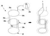
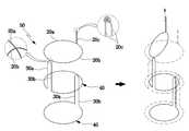
도 3 및 도 4에 도시된 바와 같이, 본 발명의 스텐트 제거용 당김줄 구조는 한 가닥 또는 그 이상의 가닥의 형상기억합금 와이어(11)를 서로 엮거나 지그 재그로 교차시켜서 공간부(12)를 형성하며 양 끝단에는 다수개의 절곡단(13)이 원주를 따라 형성된 원통형 몸체(14)로 이루어진 스텐트(10) 제거를 위한 당김줄에 관한 것으로, 상기 원통형 몸체(14)의 공간부(12)에 지그 재그로 원형 띠 형태가 되도록 엮어서 형성되는 끝단 당김줄(20)의 양단을 묶어 걸고리(21)를 형성한다.As shown in Figure 3 and 4, the stent removal pull string structure of the present invention weave the
그리고, 상기 원통형 몸체(14)의 길이방향으로 위치된 공간부(12)를 통과하여 원통형 몸체(14)의 내경을 지나 외부로 노출되게 이웃하는 공간부(12)를 통과하는 길이방향 당김줄(30)의 일단을 끝단 당김줄(20)에 일체로 연장 또는 묶어서 연결한다.In addition, the longitudinal pull line passing through the
이후, 상기 원통형 몸체(14)의 원주방향으로 위치된 공간부(12)에 지그재그 로 엮어지는 원형 띠 형상의 원주방향 당김줄(40)을 하나 이상으로 형성하여 길이방향 당김줄(30)의 타단에 일체로 연장 또는 묶어서 연결되는 당김줄(50)이 적용된 스텐트(10)가 구성된다.Subsequently, the other end of the
즉, 상기 스텐트(10)는 상기 걸고리(21)를 당길 경우 끝단 당김줄(20)과 길이방향 당김줄(30)과 원주방향 당김줄(40)이 순차적으로 당겨지되, 상기 끝단 당김줄(20)은 원통형 몸체(14)의 직경방향과 길이방향으로 당겨지고, 상기 길이방향 당김줄(30)은 원통형 몸체(14)의 길이방향으로 당겨지며, 상기 원주방향 당김줄(40)은 원통형 몸체(14)의 직경방향으로 당겨져 장기 내벽에서 쉽게 분리되어 제거가 용이하도록 형성되도록 구성되는 것이다.That is, when the
1. 도 4에 도시된 바와 같이, 일 실시 예로써 상기 당김줄(50)은 제1 끝단 당김줄(20a)과, 제1 길이방향 당김줄(30a)과, 원주방향 당김줄(40)과, 제2 길이방향 당김줄(30b)과 제2 끝단 당김줄(20b)은 일체가 되도록 구성된다.1. As shown in Figure 4, in one embodiment the
상기 제1 끝단 당김줄(20a)은 일단을 스텐트(10) 원통형 몸체(14)의 공간부(12)에 지그 재그로 엮어서 반원 띠 형상으로 형성된다.The first
상기 제1 길이방향 당김줄(30a)은 제1 끝단 당김줄(20a)을 형성한 일단이 원통형 몸체(14)의 길이방향으로 위치된 공간부(12)를 통과하여 원통형 몸체(14)의 내경을 지나 외부로 노출되게 이웃하는 공간부(12)를 통과하여 형성된다.The first
상기 원주방향 당김줄(40)은 제1 길이방향 당김줄(30a)을 형성한 일단이 원통형 몸체(14)의 원주방향으로 위치된 공간부(12)에 엮여져 반원 띠 또는 원형 띠 형상이 되게 하나 이상으로 형성한다.The
그리고, 상기 원주방향 당김줄(40)을 형성한 일단이 제1 길이방향 당김줄(30a)과 제1 끝단 당김줄(20a)에 이격되어 마주보는 형태의 제2 길이방향 당김줄(30b)과 제2 끝단 당김줄(20b)을 순차로 형성 후 양 단을 묶어 걸고리(20c)가 형성한다.Then, one end of the
즉, 상기 당김줄(50)은 제1 끝단 당김줄(20a)과, 제1 길이방향 당김줄(30a)과, 원주방향 당김줄(40)과, 제2 길이방향 당김줄(30b)과 제2 끝단 당김줄(20b)은 하나의 줄로 연장되게 구성된 것이다.That is, the
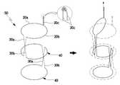
2. 도 5에 도시된 바와 같이, 일 실시 예로써 상기 당김줄(50)은 제1 끝단 당김줄(20a)과, 제1 길이방향 당김줄(30a)과, 원주방향 당김줄(40)과, 제2 길이방향 당김줄(30b)과 제2 끝단 당김줄(20b)은 일체가 되도록 구성된다.2. As shown in FIG. 5, in one embodiment, the
상기 제1 끝단 당김줄(20a)은 당김줄(50)은 일단을 스텐트(10) 원통형 몸체(14)의 공간부(12)에 지그 재그로 엮어서 반원 띠 형상으로 형성한다.The first end pull string (20a) is a
상기 제1 길이방향 당김줄(30a)는 제1 끝단 당김줄(20a)을 형성한 일단이 원통형 몸체(14)의 길이방향으로 위치된 공간부(12)를 통과하여 원통형 몸체(14)의 내경을 지나 외부로 노출되게 이웃하는 공간부(12)를 통과하도록 형성한다.The first
상기 원주방향 당김줄(40)은 제1 길이방향 당김줄(30a)을 형성한 일단이 원통형 몸체(14)의 원주방향으로 위치된 공간부(12)에 엮여져 원형 띠 형상이 되게 하나 이상으로 형성한다.The
그리고, 상기 원주방향 당김줄(40)을 형성한 일단이 제1 길이방향 당김줄(30a)과 교차되게 제2 길이방향 당김줄(30b)을 형성시키고 제1 끝단 당김줄(20a) 에 이격되어 마주보는 형태의 제2 끝단 당김줄(20b)을 순차로 형성 후 양 단을 묶어 걸고리(20c)가 형성되도록 구성한다.Then, one end of the
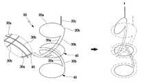
3. 도 6에 도시된 바와 같이, 또 다른 실시 예로써 상기 당김줄(50)은 제1 끝단 당김줄(20a)과, 제1 길이방향 당김줄(30a)과, 원주방향 당김줄(40)과, 제2 길이방향 당김줄(30b)과, 제2 끝단 당김줄(20b)로 구성된다.3. As shown in FIG. 6, as another embodiment, the
상기 제1 끝단 당김줄(20a)은 일단을 스텐트(10) 원통형 몸체(14)의 공간부(12)에 지그 재그로 엮어서 반원 띠 형상으로 형성한다.The first
상기 제1 길이방향 당김줄(30a)은 제1 끝단 당김줄(20a)을 형성한 일단이 원통형 몸체(14)의 대각선 길이방향으로 위치된 공간부(12)를 통과하여 원통형 몸체(14)의 내경을 지나 외부로 노출되게 이웃하는 공간부(12)를 통과하여 형성된다.The first
상기 원주방향 당김줄(40)은 제1 길이방향 당김줄(30a)을 형성한 일단이 원통형 몸체(14)의 원주방향으로 위치된 다수개의 공간부(12)에 엮여져 원형 띠 형상이며 하나 이상으로 형성된다.The
상기 제2 길이방향 당김줄(30b)은 원주방향 당김줄(40)을 형성한 일단이 제1 길이방향 당김줄(30a)과 교차되도록 공간부(12)에 지그 재그로 엮여져 형성된다.The second
상기 제2 끝단 당김줄(20b)는 제1 끝단 당김줄(20a)에 이격되어 마주보게 형성한 후 양단을 묶어 걸고리(20c)를 형성시켜 구성된다.The second
즉, 제1 끝단 당김줄(20a)과, 제1 길이방향 당김줄(30a)과, 원주방향 당김줄(40)과, 제2 길이방향 당김줄(30b)과, 제2 끝단 당김줄(20b)은 하나의 줄로 일체로 구성된 것이다.That is, the first
4. 도 7에 도시된 바와 같이, 또 다른 실시 예로써 상기 당김줄(50)은 스텐트(10) 원통형 몸체(14)의 공간부(12)에 지그 재그로 엮여져 형성되는 원형 띠 형상의 끝단 당김줄(20)의 양단을 묶어서 걸고리(21)를 형성한다.4. As shown in FIG. 7, in another embodiment, the pulling
그리고, 상기 원통형 몸체(14)의 길이방향으로 위치된 공간부(12)를 통과하여 원통형 몸체(14)의 내경을 지나 외부로 노출되게 이웃하는 공간부(12)를 통과하는 하나 이상의 길이방향 당김줄(30)을 형성한 후 일단을 끝단 당김줄(20)의 걸고리(21)에 묶어서 연결한다.And one or more longitudinal pulls passing through the spaced
더불어, 상기 원통형 몸체(14)의 원주방향으로 위치된 공간부(12)에 엮여져 형성되는 원형 띠 형상의 원주방향 당김줄(40)을 하나 이상으로 형성하여 각각 길이방향 당김줄(30)의 타단에 묶어서 연결 구성한다.In addition, by forming one or more circular band-shaped
5. 도 8에 도시된 바와 같이, 또 다른 실시 예로써 상기 당김줄(50)은 스텐트(10) 원통형 몸체(14)의 공간부(12)에 지그 재그로 엮여져 형성되는 원형 띠 형상의 끝단 당김줄(20)의 양단을 묶어서 걸고리(21)를 형성한다.5. As shown in FIG. 8, in another embodiment, the pulling
그리고, 상기 원통형 몸체(14)의 원주방향으로 위치된 공간부(12)에 엮여져 형성되는 원형 띠 형상의 원주방향 당김줄(40)을 하나 이상으로 형성한 후 양단을 묶어서 형성되는 원주당김줄걸고리(41)를 끝단 당김줄(20)의 걸고리(21)를 묶어서 연결 구성한다.In addition, a circumferential pull line is formed by tying both ends after forming at least one circular band-shaped
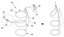
6. 도 9에 도시된 바와 같이, 또 다른 실시 예로써 상기 당김줄(50)은 일단을 스텐트(10) 원통형 몸체(14)의 공간부(12)에 지그 재그로 엮어서 반원 띠 형상의 제1 끝단 당김줄(20a)을 형성한다.6. As shown in FIG. 9, in another embodiment, the pulling
그리고, 상기 제1 끝단 당김줄(20a)을 형성한 일단이 원통형 몸체(14)의 길이방향으로 위치된 공간부(12)를 통과하여 원통형 몸체(14)의 내경을 지나 외부로 노출되게 이웃하는 공간부(12)를 통과하는 제1 길이방향 당김줄(30a)을 형성한다.Then, one end forming the first
더불어, 상기 제1길이방향 당김줄(30a)을 형성한 일단이 원통형 몸체(14)의 원주방향으로 위치된 다수개의 공간부(12)에 엮여져 원형 띠 형상의 원주방향 당김줄(40)을 하나 이상으로 형성한다.In addition, one end of the first longitudinal
아울러, 상기 원주방향 당김줄(40)을 형성한 일단이 제1 길이방향 당김줄(30a)과 원주상에서 교차되도록 공간부(12)에 지그 재그로 엮여져 제2 길이방향 당김줄(30b)을 형성하고, 상기 제1 끝단 당김줄(20a)에 이격되어 마주보는 제2 끝단 당김줄(20b)을 형성한 후 양단을 묶어 걸고리(20c)를 형성시켜 구성한다.In addition, one end of the
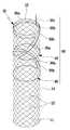
도 22에 도시된 바와 같이, 다른 형태에 따른 예로써 한 가닥 또는 그 이상의 가닥의 형상기억합금 와이어(11)를 서로 엮거나 지그 재그로 교차시켜서 공간부(12)를 형성하며 양 끝단에는 다수개의 절곡단(13)이 원주를 따라 형성된 원통형 몸체(14)의 내부로 의료용 피막(15)이 접착되어 이루어진 스텐트에 관한 것이다.As shown in FIG. 22, as an example according to another form, the shape
상기 원통형 몸체(14)의 공간부(12)와 피막(15)을 통과하면서 지그 재그로 원형 띠 형태가 되도록 엮어서 형성되는 끝단 당김줄(20)의 양단을 묶어 걸고리(21)를 형성한다.Passing through the
그리고, 상기 원통형 몸체(14)의 길이방향 공간부(12)와 피막(15)을 관통하면서 원통형 몸체(14)의 내경을 지나 외부로 노출되게 이웃하는 공간부(12)를 통과하는 길이방향 당김줄(30)의 일단이 끝단 당김줄(20)에 일체로 연장 또는 묶어서 연결한다.And, the longitudinal pull passing through the
이후, 상기 원통형 몸체(14)의 원주방향 공간부(12)와 피막(15)을 관통하면서 지그재그로 엮어지는 원형 띠 형상의 원주방향 당김줄(40)을 하나 이상으로 형성하여 길이방향 당김줄(30)의 타단에 일체로 연장 또는 묶어서 연결되는 당김줄(50)로 스텐트(10)가 구성된다.Subsequently, a
즉, 상기 스텐트(10)는 걸고리(21)를 당길 경우 끝단 당김줄(20)과 길이방향 당김줄(30)과 원주방향 당김줄(40)이 순차적으로 당겨지되, 상기 끝단 당김줄(20)은 원통형 몸체(14)의 직경방향과 길이방향으로 당겨지고, 상기 길이방향 당김줄(30)은 원통형 몸체(14)의 길이방향으로 당겨지며, 상기 원주방향 당김줄(40)은 원통형 몸체(14)의 직경방향으로 축소되도록 당겨져 장기 내벽에서 쉽게 분리되어 제거가 용이하도록 형성되도록 구성된 것이다.That is, when the
1. 도 4에 도시된 바와 같이, 일 실시 예로써 상기 당김줄(50)은 제1 끝단 당김줄(20a)과, 제1 길이방향 당김줄(30a)과, 원주방향 당김줄(40)과, 제2 길이방향 당김줄(30b)과 제2 끝단 당김줄(20b)은 일체가 되도록 구성된다.1. As shown in Figure 4, in one embodiment the
상기 제1 끝단 당김줄(20a)은 일단을 스텐트(10) 원통형 몸체(14)의 공간부(12)와 피막(15)을 통과하면서 지그 재그로 엮어서 반원 띠 형상으로 형성된다.The first
상기 제1 길이방향 당김줄(30a)은 제1 끝단 당김줄(20a)을 형성한 일단이 원통형 몸체(14)의 길이방향으로 위치된 공간부(12)와 피막(15)을 통과하여 원통형 몸체(14)의 내경을 지나 외부로 노출되게 이웃하는 공간부(12)와 피막(15)을 통과하면서 통과하여 형성된다.The first
상기 원주방향 당김줄(40)은 제1 길이방향 당김줄(30a)을 형성한 일단이 원통형 몸체(14)의 원주방향으로 위치된 공간부(12)와 피막(15)을 통과하면서 엮여져 반원 띠 또는 원형 띠 형상이 되게 하나 이상으로 형성한다.The
그리고, 상기 원주방향 당김줄(40)을 형성한 일단이 제1 길이방향 당김줄(30a)과 제1 끝단 당김줄(20a)에 이격되어 마주보는 형태의 제2 길이방향 당김줄(30b)과 제2 끝단 당김줄(20b)을 순차로 형성 후 양 단을 묶어 걸고리(20c)가 형성한다.Then, one end of the
즉, 상기 당김줄(50)은 제1 끝단 당김줄(20a)과, 제1 길이방향 당김줄(30a)과, 원주방향 당김줄(40)과, 제2 길이방향 당김줄(30b)과 제2 끝단 당김줄(20b)은 하나의 줄로 연장되게 구성된 것이다.That is, the
2. 도 5에 도시된 바와 같이, 일 실시 예로써 상기 당김줄(50)은 제1 끝단 당김줄(20a)과, 제1 길이방향 당김줄(30a)과, 원주방향 당김줄(40)과, 제2 길이방향 당김줄(30b)과 제2 끝단 당김줄(20b)은 일체가 되도록 구성된다.2. As shown in FIG. 5, in one embodiment, the pulling
상기 제1 끝단 당김줄(20a)은 당김줄(50)은 일단을 스텐트(10) 원통형 몸체(14)의 공간부(12)와 피막(15)을 통과하면서 지그 재그로 엮어서 반원 띠 형상으로 형성한다.The first end pull string (20a) is a
상기 제1 길이방향 당김줄(30a)는 제1 끝단 당김줄(20a)을 형성한 일단이 원통형 몸체(14)의 길이방향으로 위치된 공간부(12)와 피막(15)을 통과하면서 통과하여 원통형 몸체(14)의 내경을 지나 외부로 노출되게 이웃하는 공간부(12)와 피막(15)을 통과하도록 형성한다.The first
상기 원주방향 당김줄(40)은 제1 길이방향 당김줄(30a)을 형성한 일단이 원통형 몸체(14)의 원주방향으로 위치된 공간부(12)와 피막(15)을 통과하면서 엮여져 원형 띠 형상이 되게 하나 이상으로 형성한다.The
그리고, 상기 원주방향 당김줄(40)을 형성한 일단이 제1 길이방향 당김줄(30a)과 교차되게 제2 길이방향 당김줄(30b)을 형성시키고 제1 끝단 당김줄(20a)에 이격되어 마주보는 형태의 제2 끝단 당김줄(20b)을 순차로 형성 후 양 단을 묶어 걸고리(20c)가 형성되도록 구성한다.Then, one end of the
3. 도 6에 도시된 바와 같이, 또 다른 실시 예로써 상기 당김줄(50)은 제1 끝단 당김줄(20a)과, 제1 길이방향 당김줄(30a)과, 원주방향 당김줄(40)과, 제2 길이방향 당김줄(30b)과, 제2 끝단 당김줄(20b)로 구성된다.3. As shown in FIG. 6, as another embodiment, the pulling
상기 제1 끝단 당김줄(20a)은 일단을 스텐트(10) 원통형 몸체(14)의 공간부(12)와 피막(15)을 통과하면서 지그 재그로 엮어서 반원 띠 형상으로 형성한다.The first
상기 제1 길이방향 당김줄(30a)은 제1 끝단 당김줄(20a)을 형성한 일단이 원통형 몸체(14)의 대각선 길이방향으로 위치된 공간부(12)와 피막(15)을 통과하여 원통형 몸체(14)의 내경을 지나 외부로 노출되게 이웃하는 공간부(12)와 피막(15)을 통과하여 형성된다.The first
상기 원주방향 당김줄(40)은 제1 길이방향 당김줄(30a)을 형성한 일단이 원통형 몸체(14)의 원주방향으로 위치된 다수개의 공간부(12)와 피막(15)을 통과하면서 엮여져 원형 띠 형상이며 하나 이상으로 형성된다.The
상기 제2 길이방향 당김줄(30b)은 원주방향 당김줄(40)을 형성한 일단이 제1 길이방향 당김줄(30a)과 교차되도록 공간부(12)와 피막(15)을 통과하면서 지그 재그로 엮여져 형성된다.The second
상기 제2 끝단 당김줄(20b)는 제1 끝단 당김줄(20a)에 이격되어 마주보게 형성한 후 양단을 묶어 걸고리(20c)를 형성시켜 구성된다.The second
즉, 제1 끝단 당김줄(20a)과, 제1 길이방향 당김줄(30a)과, 원주방향 당김줄(40)과, 제2 길이방향 당김줄(30b)과, 제2 끝단 당김줄(20b)은 하나의 줄로 일체로 구성된 것이다.That is, the first
4. 도 7에 도시된 바와 같이, 또 다른 실시 예로써 상기 당김줄(50)은 스텐트(10) 원통형 몸체(14)의 공간부(12)와 피막(15)을 통과하면서 지그 재그로 엮여져 형성되는 원형 띠 형상의 끝단 당김줄(20)의 양단을 묶어서 걸고리(21)를 형성한다.4. As shown in FIG. 7, as another embodiment, the pulling
그리고, 상기 원통형 몸체(14)의 길이방향으로 위치된 공간부(12)를 통과하여 원통형 몸체(14)의 내경을 지나 외부로 노출되게 이웃하는 공간부(12)와 피막(15)을 통과하면서 통과하는 하나 이상의 길이방향 당김줄(30)을 형성한 후 일단을 끝단 당김줄(20)의 걸고리(21)에 묶어서 연결한다.Then, while passing through the
더불어, 상기 원통형 몸체(14)의 원주방향으로 위치된 공간부(12)와 피막(15)을 통과하면서 엮여져 형성되는 원형 띠 형상의 원주방향 당김줄(40)을 하나 이상으로 형성하여 각각 길이방향 당김줄(30)의 타단에 묶어서 연결 구성한다.In addition, at least one circular band-shaped
5. 도 8에 도시된 바와 같이, 또 다른 실시 예로써 상기 당김줄(50)은 스텐트(10) 원통형 몸체(14)의 공간부(12)와 피막(15)을 통과하면서 지그 재그로 엮여 져 형성되는 원형 띠 형상의 끝단 당김줄(20)의 양단을 묶어서 걸고리(21)를 형성한다.5. As shown in FIG. 8, as another embodiment, the pulling
상기 원통형 몸체(14)의 원주방향으로 위치된 공간부(12)와 피막(15)을 통과하면서 엮여져 형성되는 원형 띠 형상의 원주방향 당김줄(40)을 하나 이상으로 형성한 후 양단을 묶어서 형성되는 원주당김줄걸고리(41)를 끝단 당김줄(20)의 걸고리(21)를 묶어서 연결 구성한다.After forming at least one circular band-shaped
6. 도 9에 도시된 바와 같이, 또 다른 실시 예로써 상기 당김줄(50)은 일단을 스텐트(10) 원통형 몸체(14)의 공간부(12)와 피막(15)을 통과하면서 지그 재그로 엮어서 반원 띠 형상의 제1 끝단 당김줄(20a)을 형성한다.6. As shown in FIG. 9, in another embodiment, the pulling
그리고, 상기 제1 끝단 당김줄(20a)을 형성한 일단이 원통형 몸체(14)의 길이방향으로 위치된 공간부(12)와 피막(15)을 통과하면서 통과하여 원통형 몸체(14)의 내경을 지나 외부로 노출되게 이웃하는 공간부(12)를 통과하는 제1 길이방향 당김줄(30a)을 형성한다.One end of the first
더불어, 상기 제1 길이방향 당김줄(30a)을 형성한 일단이 원통형 몸체(14)의 원주방향으로 위치된 다수개의 공간부(12)와 피막(15)을 통과하면서 엮여져 원형 띠 형상의 원주방향 당김줄(40)을 하나 이상으로 형성한다.In addition, one end of the first
아울러, 상기 원주방향 당김줄(40)을 형성한 일단이 제1 길이방향 당김줄(30a)과 원주상에서 교차되도록 공간부(12)와 피막(15)을 통과하면서 지그 재그로 엮여져 제2 길이방향 당김줄(30b)을 형성하고, 상기 제1 끝단 당김줄(20a)에 이격되어 마주보는 제2 끝단 당김줄(20b)을 형성한 후 양단을 묶어 걸고리(20c)를 형 성시켜 구성한다.In addition, one end of the
공통적으로, 상기 하나 이상으로 형성되는 원주방향 당김줄(40)의 상호간격은 병변부위 면적이나 스텐트(10)의 총 길이에 따라 다르게 형성된다.In general, the mutual spacing of the
또한, 상기 길이방향 당김줄(30)의 길이는 병변부위 면적이나 스텐트(10)의 총 길이에 따라 다르게 형성된다.In addition, the length of the
그리고, 상기 제1,2길이방향 당김줄(30a)(30b)은 스텐트(10) 원통형 몸체(14)의 길이방향으로 위치되는 공간부(12)와 피막(15)을 통과하면서 지그 재그로 엮어서 구성한다.The first and second
더불어, 상기 길이방향 당김줄(30)은 원통형 몸체(14)의 길이방향으로 위치되는 공간부(12)에 지그 재그로 엮어서 구성될 수도 있다.In addition, the
아울러, 상기 당김줄(50)은 의료용 섬유재, 합성수지재, 비철금속재, 금속재 와이어 중 어느 하나로 구성된다.In addition, the
한편, 상기 당김줄(50)은 원통형태의 스텐트, 양단이 외측으로 확장된 스텐트, 양단이 내측으로 좁아지는 스텐트에 적용가능 할 것이다.On the other hand, the
상기와 같이 구성된 본 발명의 작동 및 작용을 설명하면 다음과 같다.Hereinafter, the operation and operation of the present invention will be described.
먼저 상기 스텐트(10)는 인체의 장기에 병변이 발생되어 장기의 직경이 병변의 확대로 인하여 협소해지는 병변부위를 확장시키기 위해 시술된다.First, the
간단히, 시술과정을 살펴보면 장기내의 병변부위를 확인한 후 인체의 내로 스텐트(10)를 스텐트 시술장치(도면상 미도시)를 이용하여 삽입하여 협착되어진 병변부위를 확장시키는 것이다.Briefly, the procedure is to check the lesions in the organs and then expand the constricted lesions by inserting the
이렇게, 시술된 스텐트(10)는 인체의 장기내에서 병변부위가 완치될 때까지 시술한 상태를 유지하게 되는데 기간은 대략 6개월 정도로 유지하게 되며 이때, 시술 기간은 병변부위의 특성이나 경과상태에 따라 다르게 적용된다.In this way, the treated
그러나, 오랜 기간에 걸쳐 스텐트(10)를 장기 내의 병변부위(300)에 시술 해 놓을 경우 병변부위(300)의 조직이 공간부(12)로 밀려들어와 침착되는 현상이 발생 될 때 당김줄(50)을 이용하여 스텐트(10)를 병변부위(300)나 인체조직에서 간단하게 분리할 수 있다.However, when the
그리고, 상기 병변부위(300)가 완치되어 제거 시술을 하거나 스텐트(10)의 재 시술을 위해 교체 시술을 스텐트 제거장치를 이용하여 시행한다.Then, the
여기서, 상기 스텐트(10)를 제거하기 위하여 6가지 실시 예에 따른 당김줄(50)을 살펴보는데 1번, 2번, 3번 실시 예는 각각 설명한다.Here, look at the pulling
첫째, 도 4, 도 10, 도 16에 도시된 바와 같이 1번 실시 예의 상기 당김줄(50)은 인출 방향으로 당기게 되면 당김력은 걸고리(20c) -> 제1,2 끝단 당김줄(20a)(20b) -> 제1,2 길이방향 당김줄(30a)(30b) -> 원주방향 당김줄(40)의 순서로 전달되면서 스텐트(10)는 전체적으로 직경이 작아지는 동시에 길이가 신장되는 상태가 된다.First, as shown in FIGS. 4, 10, and 16, when the pulling
이때, 상기 제1,2 끝단 당김줄(20a)(20b)은 당김력에 의해 당기는 쪽으로 당겨지면서 원통형 몸체(14)의 직경 중심방향으로 직경이 축소되어 원통형 몸체(14)를 가압하게 된다.At this time, the first and second end pull string (20a, 20b) is pulled toward the pull by the pulling force is reduced in diameter in the diameter center direction of the
그리고, 상기 제1,2 길이방향 당김줄(30a)(30b)은 제1,2 끝단 당김 줄(20a)(20b)에 의해 전달되는 당김력에 의해 스텐트(10)의 길이방향으로 당겨지게 된다.The first and second
또한, 상기 원주방향 당김줄(40)은 제1,2 끝단 당김줄(20a)(20b)과 제1,2 길이방향 당김줄(30a)(30b)을 통해 전달되는 당김력에 의해 스텐트(10)의 원통형 몸체(14)를 가압하여 직경이 축소되도록 한다.In addition, the
이로써, 상기 스텐트(10)가 인체조직에 침착되어진 상태에서도 제1,2 끝단 당김줄(20a)(20b)과 제1,2 길이방향 당김줄(30a)(30b)에 의해 스텐트(10)가 길이방향으로 신장되는 동시에 원주방향 당김줄(40)에 의해 원주방향 중심으로 직경이 축소되어 침착된 인체조직으로부터 쉽게 분리/이탈되어 제거되며 고통발생이나 2차적인 상처의 유발이 방지되는 것이다.Thus, even when the
둘째, 도 5, 도 11, 도 17에 도시된 바와 같이 2번 실시 예의 상기 당김줄(50)은 인출 방향으로 당기게 되면 당김력은 걸고리(20c) -> 제1,2 끝단 당김줄(20a)(20b) -> 제1,2 길이방향 당김줄(30a)(30b) -> 원주방향 당김줄(40)의 순서로 전달되면서 스텐트(10)는 전체적으로 직경이 작아지는 동시에 길이가 신장되는 상태가 된다.Second, as shown in Figures 5, 11, 17, the
이때, 상기 제1,2 끝단 당김줄(20a)(20b)은 당김력에 의해 당기는 쪽으로 당겨지면서 원통형 몸체(14)의 직경 중심방향으로 직경이 축소되어 원통형 몸체(14)를 가압하게 된다.At this time, the first and second end pull string (20a, 20b) is pulled toward the pull by the pulling force is reduced in diameter in the diameter center direction of the
그리고, 상기 제1,2 길이방향 당김줄(30a)(30b)은 제1,2 끝단 당김줄(20a)(20b)에 의해 전달되는 당김력에 의해 스텐트(10)의 교차되게 길이방향으로 당겨지게 된다.The first and second
또한, 상기 원주방향 당김줄(40)은 제1,2 끝단 당김줄(20a)(20b)과 제1,2 길이방향 당김줄(30a)(30b)을 통해 전달되는 당김력에 의해 스텐트(10)의 원통형 몸체(14)를 가압하여 직경이 축소되도록 한다.In addition, the
이로써, 상기 스텐트(10)가 인체조직에 침착되어진 상태에서도 제1,2 끝단 당김줄(20a)(20b)과 제1,2 길이방향 당김줄(30a)(30b)에 의해 스텐트(10)가 길이방향으로 신장되는 동시에 원주방향 당김줄(40)에 의해 원주방향 중심으로 직경이 축소되어 침착된 인체조직으로부터 쉽게 분리/이탈되어 제거되며 고통발생이나 2차적인 상처의 유발이 방지되는 것이다.Thus, even when the
셋째, 도 6, 도 12, 도 18에 도시된 바와 같이 3번 실시 예의 상기 당김줄(50)은 인출 방향으로 당기게 되면 당김력은 걸고리(20c) -> 제1,2 끝단 당김줄(20a)(20b) -> 제1,2 길이방향 당김줄(30a)(30b) -> 원주방향 당김줄(40)의 순서로 전달되면서 스텐트(10)는 전체적으로 직경이 작아지는 동시에 길이가 신장되는 상태가 된다.Third, as shown in FIGS. 6, 12, and 18, when the pulling
이때, 상기 제1,2 끝단 당김줄(20a)(20b)은 당김력에 의해 당기는 쪽으로 당겨지면서 원통형 몸체(14)의 직경 중심방향으로 직경이 축소되어 원통형 몸체(14)를 가압하게 된다.At this time, the first and second end pull string (20a, 20b) is pulled toward the pull by the pulling force is reduced in diameter in the diameter center direction of the
그리고, 상기 대각선 방향으로 위치되는 제1,2 길이방향 당김줄(30a)(30b)은 제1,2 끝단 당김줄(20a)(20b)에 의해 전달되는 당김력에 의해 스텐트(10)의 길이방향과 원주방향 중심쪽으로 동시에 당겨지게 된다.The first and second
또한, 상기 원주방향 당김줄(40)은 제1,2 끝단 당김줄(20a)(20b)과 제1,2 길이방향 당김줄(30a)(30b)을 통해 전달되는 당김력에 의해 스텐트(10)의 원통형 몸체(14)를 가압하여 직경이 축소되도록 한다.In addition, the
이로써, 상기 스텐트(10)가 인체조직에 침착되어진 상태에서도 제1,2 끝단 당김줄(20a)(20b)과 제1,2 길이방향 당김줄(30a)(30b)에 의해 스텐트(10)가 길이방향으로 신장되는 동시에 원주방향 당김줄(40)에 의해 원주방향 중심으로 직경이 축소되어 침착된 인체조직으로부터 쉽게 분리/이탈되어 제거되며 고통발생이나 2차적인 상처의 유발이 방지되는 것이다.Thus, even when the
넷째, 도 7, 도 13, 도 19에 도시된 바와 같이 4번 실시 예의 상기 당김줄(50)은 인출 방향으로 당기게 되면 당김력은 걸고리(21) -> 각각의 길이방향 당김줄(30) -> 각각의 원주방향 당김줄(40)의 순서로 전달되면서 스텐트(10)는 전체적으로 직경이 작아지는 동시에 길이가 신장되는 상태가 된다.Fourth, as shown in Figure 7, Figure 13, Figure 19, the
이때, 상기 끝단 당김줄(20)은 당김력에 의해 당기는 쪽으로 당겨지면서 원통형 몸체(14)의 직경 중심방향으로 직경이 축소되어 원통형 몸체(14)를 가압하게 된다.At this time, the
그리고, 상기 길이방향 당김줄(30)은 끝단 당김줄(20)에 의해 전달되는 당김력에 의해 스텐트(10)의 길이방향과 원주방향 중심쪽으로 동시에 당겨지게 된다.Then, the
또한, 상기 원주방향 당김줄(40)은 끝단 당김줄(20)과 길이방향 당김줄(30)을 통해 전달되는 당김력에 의해 스텐트(10)의 원통형 몸체(14)를 가압하여 직경이 축소되도록 한다.In addition, the
다섯째, 도 8, 도 14, 도 20에 도시된 바와 같이 5번 실시 예의 상기 당김줄(50)은 인출 방향으로 당기게 되면 당김력은 걸고리(21) -> 각각의 원주방향 당김줄(40) 원주당김줄걸고리(41) -> 각각의 원주방향 당김줄(40)의 순서로 전달되면서 스텐트(10)는 전체적으로 직경이 작아지는 동시에 길이가 신장되는 상태가 된다.Fifth, as shown in Figure 8, Figure 14, 20, the pulling
이때, 상기 끝단 당김줄(20)은 당김력에 의해 당기는 쪽으로 당겨지면서 원통형 몸체(14)의 직경 중심방향으로 직경이 축소되어 원통형 몸체(14)를 가압하게 된다.At this time, the
그리고, 상기 원주당김줄걸고리(41) 및 원주방향 당김줄(40)은 끝단 당김줄(20)에 의해 전달되는 당김력에 의해 스텐트(10)의 길이방향과 원주 중심 쪽으로 동시에 당겨지게 된다.Then, the circumferential
또한, 상기 원주방향 당김줄(40)은 끝단 당김줄(20)과 원주당김줄걸고리(41)을 통해 전달되는 당김력에 의해 스텐트(10)의 원통형 몸체(14)를 가압하여 직경이 축소되도록 한다.In addition, the
여섯째, 도 9, 도 15, 도 21에 도시된 바와 같이 6번 실시 예의 상기 당김줄(50)은 인출 방향으로 당기게 되면 당김력은 걸고리(20c) -> 제1,2 끝단 당김줄(20a)(20b) -> 제1,2 길이방향 당김줄(30a)(30b) -> 원주방향 당김줄(40)의 순서로 전달되면서 스텐트(10)는 전체적으로 직경이 작아지는 동시에 길이가 신장되는 상태가 된다.Sixth, as shown in Figure 9, Figure 15, 21, the pulling
이때, 상기 제1,2 끝단 당김줄(20a)(20b)은 당김력에 의해 당기는 쪽으로 당 겨지면서 원통형 몸체(14)의 직경 중심방향으로 직경이 축소되어 원통형 몸체(14)를 가압하게 된다.At this time, the first and second end pull string (20a) (20b) is pulled toward the pull by the pulling force while reducing the diameter in the diameter center direction of the
그리고, 상기 대각선 방향으로 위치되는 제1,2 길이방향 당김줄(30a)(30b)은 제1,2 끝단 당김줄(20a)(20b)에 의해 전달되는 당김력에 의해 스텐트(10)의 길이방향과 원주방향 중심쪽으로 동시에 당겨지게 된다.The first and second
또한, 상기 원주방향 당김줄(40)은 제1,2 끝단 당김줄(20a)(20b)과 제1,2 길이방향 당김줄(30a)(30b)을 통해 전달되는 당김력에 의해 스텐트(10)의 원통형 몸체(14)를 가압하여 직경이 축소되도록 한다.In addition, the
즉, 상기 제1 길이방향 당김줄(30a)과 제2 길이방향 당김줄(30b)을 원주상에서 마주보게 교차되어 당김력에 의해 길이방향의 당김력과 원주방향의 당김력이 동시에 발생되는 것이다.That is, the first
이로써, 인체의 장기 중 병변부위(300)가 발병된 장기내에 스텐트(10)를 시술할 경우 공간부(12)를 통해 병변부위(300)나 인체조직이 침착되더라도 스테트(100)의 제거 시술시 상처의 유발을 방지하고 환자에게 고통이 발생되지 않도록 하는 이점이 있다.Thus, when the
더불어, 상기 당김줄(50)을 당겼을 때 스텐트(10)가 길이방향으로 신장되면서 원주방향의 중심으로 직경이 축소되어 병변부위(300)나 인체조직에서 쉽게 이탈되어 제거가 용이해지는 장점이 있다.In addition, when the
아울러, 상기 원주방향 당김줄(40)의 상호간격이나 길이방향 당김줄(30)의 을 병변부위(300)가 넓을 경우 좁게 하여 이탈력을 집중시켜 분리가 더욱 용이하도 록 하는 이점이 있는 것이다.In addition, there is an advantage that the separation between the circumferential direction of the pulling
이상에서는 본 발명을 특정의 바람직한 실시예를 예를들어 도시하고 설명하였으나, 본 발명은 상기한 실시예에 한정되지 아니하며 본 발명의 정신을 벗어나지 않는 범위내에서 당해 발명이 속하는 기술분야에서 통상의 지식을 가진자에 의해 다양한 변경과 수정이 가능할 것이다.In the above, the present invention has been illustrated and described with reference to specific preferred embodiments, but the present invention is not limited to the above-described embodiments and is not limited to the spirit of the present invention. Various changes and modifications can be made by those who have
도 1은 종래의 스텐트가 병변부위에 시술도 및 공간부로 인체조직이 침착된 상태를 나타낸 확대 단면도,1 is an enlarged cross-sectional view showing a state in which a conventional stent is deposited on the lesion site of the human tissue as a surgical diagram and a space;
도 2는 종래의 스텐트를 제거 시술시 공간부에 침착된 인체조직이 걸려지는 상태를 나타낸 시술도 및 확대 단면도,Figure 2 is a surgical diagram and an enlarged cross-sectional view showing a state in which the human tissue deposited on the space is caught when the conventional stent removal procedure;
도 3은 본 발명에 따른 당김줄이 적용되는 스텐트의 사시도 및 적용된 상태의 사시도,3 is a perspective view of the stent to which the pulling string according to the present invention and applied state,
도 4는 도 3에 실시 예에 따른 당김줄의 형태를 나타낸 사시도 및 작동 상태도,Figure 4 is a perspective view and an operational state diagram showing the shape of the pull string according to the embodiment in Figure 3,
도 5는 일 실시 예에 따른 당김줄의 형태를 나타낸 사시도 및 작동 상태도,5 is a perspective view and an operational state diagram showing the shape of a pull string according to an embodiment;
도 6은 일 실시 예에 따른 당김줄의 형태를 나타낸 사시도 및 작동 상태도,6 is a perspective view and an operational state diagram showing the shape of a pull string according to one embodiment;
도 7은 일 실시 예에 따른 당김줄의 형태를 나타낸 사시도 및 작동 상태도,7 is a perspective view and an operational state diagram showing the shape of a pull string according to an embodiment;
도 8은 일 실시 예에 따른 당김줄의 형태를 나타낸 사시도 및 작동 상태도,8 is a perspective view and an operational state diagram showing the shape of a pull string according to one embodiment;
도 9는 일 실시 예에 따른 당김줄의 형태를 나타낸 사시도 및 작동 상태도,9 is a perspective view and an operational state diagram showing the shape of a pull string according to one embodiment;
도 10은 도 4의 당김줄이 원통형 스텐트에 적용된 사시도,10 is a perspective view of the pull string of FIG. 4 applied to a cylindrical stent;
도 11은 도 5의 당김줄이 원통형 스텐트에 적용된 사시도,Figure 11 is a perspective view of the pull string of Figure 5 applied to the cylindrical stent,
도 12는 도 6의 당김줄이 원통형 스텐트에 적용된 사시도,12 is a perspective view of the pull string of FIG. 6 applied to a cylindrical stent;
도 13은 도 7의 당김줄이 원통형 스텐트에 적용된 사시도,Figure 13 is a perspective view of the pull string of Figure 7 applied to the cylindrical stent,
도 14는 도 8의 당김줄이 원통형 스텐트에 적용된 사시도,Figure 14 is a perspective view of the pull string of Figure 8 applied to the cylindrical stent,
도 15는 도 9의 당김줄이 원통형 스텐트에 적용된 사시도,Figure 15 is a perspective view of the pull string of Figure 9 applied to the cylindrical stent,
도 16은 도 4의 당김줄이 양단이 확장된 스텐트에 적용된 사시도,Figure 16 is a perspective view of the pull string of Figure 4 is applied to the stent is extended both ends,
도 17은 도 5의 당김줄이 양단이 확장된 스텐트에 적용된 사시도,FIG. 17 is a perspective view of the pulling string of FIG. 5 applied to the stent having both ends extended; FIG.
도 18은 도 6의 당김줄이 양단이 확장된 스텐트에 적용된 사시도,18 is a perspective view of the pull string of FIG. 6 applied to the stent having both ends extended;
도 19는 도 7의 당김줄이 양단이 확장된 스텐트에 적용된 사시도,19 is a perspective view of the pull string of FIG. 7 applied to the both ends of the stent expanded;
도 20은 도 8의 당김줄이 양단이 확장된 스텐트에 적용된 사시도,20 is a perspective view of the pull string of FIG. 8 applied to a stent having both ends extended;
도 21은 도 9의 당김줄이 양단이 확장된 스텐트에 적용된 사시도,Figure 21 is a perspective view of the pull string of Figure 9 is applied to the stent is extended both ends,
도 22는 도 4의 당김줄이 내측에 피막이 부착된 원통형 스텐트에 적용된 사시도,FIG. 22 is a perspective view of the pulling line of FIG. 4 applied to a cylindrical stent having an inner coating film;
도 23은 도 4의 당김줄이 적용된 원통형 스텐트가 병변부위에 시술된 시술도 및 공간부로 인체조직이 침착된 상태를 나타낸 확대 단면도,FIG. 23 is an enlarged cross-sectional view illustrating a state where human tissue is deposited into a surgical diagram and a space portion in which a cylindrical stent to which the pull string of FIG. 4 is applied is applied to a lesion site; FIG.
도 24는 스텐트를 제거 시술을 위해 당김줄을 당길 때 공간부에 침착된 인체조직이 이탈되는 상태를 나타낸 시술도 및 확대 단면도이다.24 is a diagram illustrating an enlarged cross-sectional view showing a state in which the human tissue deposited on the space is separated when the pull string is pulled to remove the stent.
< 도면의 주요 부분에 대한 부호의 설명 ><Description of Symbols for Main Parts of Drawings>
10 : 스텐트 11 : 와이어10: stent 11: wire
12 : 공간부 13 : 절곡단12: space portion 13: bending section
14 : 원통형 몸체 15 : 피막14
20 : 끝단 당김줄21 : 걸고리20: end pull string 21: hook
20a : 제1 끝단 당김줄 20b : 제2 끝단 당김줄20a: first
20c : 걸고리30 : 길이방향 당김줄20c: hook 30: longitudinal pull
30a : 제1 길이방향 당김줄 30b : 제2 길이방향 당김줄30a: first
40 : 원주방향 당김줄 50 : 당김줄40: circumferential pull line 50: pull line
300 : 병변부위300: lesion area
Claims (26)
Translated fromKoreanPriority Applications (4)
| Application Number | Priority Date | Filing Date | Title |
|---|---|---|---|
| KR20090037988AKR101063429B1 (en) | 2009-04-30 | 2009-04-30 | Drawstring structure for stent removal |
| JP2010092285AJP5395727B2 (en) | 2009-04-30 | 2010-04-13 | Lead wire for stent removal |
| US12/770,491US8398699B2 (en) | 2009-04-30 | 2010-04-29 | Drawstring for removal of stent |
| CN2010101608711ACN101874753B (en) | 2009-04-30 | 2010-04-30 | Drawstring for removal of stent |
Applications Claiming Priority (1)
| Application Number | Priority Date | Filing Date | Title |
|---|---|---|---|
| KR20090037988AKR101063429B1 (en) | 2009-04-30 | 2009-04-30 | Drawstring structure for stent removal |
Publications (2)
| Publication Number | Publication Date |
|---|---|
| KR20100119067A KR20100119067A (en) | 2010-11-09 |
| KR101063429B1true KR101063429B1 (en) | 2011-09-08 |
Family
ID=43017504
Family Applications (1)
| Application Number | Title | Priority Date | Filing Date |
|---|---|---|---|
| KR20090037988AExpired - Fee RelatedKR101063429B1 (en) | 2009-04-30 | 2009-04-30 | Drawstring structure for stent removal |
Country Status (4)
| Country | Link |
|---|---|
| US (1) | US8398699B2 (en) |
| JP (1) | JP5395727B2 (en) |
| KR (1) | KR101063429B1 (en) |
| CN (1) | CN101874753B (en) |
Families Citing this family (40)
| Publication number | Priority date | Publication date | Assignee | Title |
|---|---|---|---|---|
| US8858610B2 (en) | 2009-01-19 | 2014-10-14 | W. L. Gore & Associates, Inc. | Forced deployment sequence |
| KR101238720B1 (en)* | 2010-11-22 | 2013-03-04 | 주식회사 엠아이텍 | Stent for removal |
| US9744033B2 (en) | 2011-04-01 | 2017-08-29 | W.L. Gore & Associates, Inc. | Elastomeric leaflet for prosthetic heart valves |
| US10117765B2 (en) | 2011-06-14 | 2018-11-06 | W.L. Gore Associates, Inc | Apposition fiber for use in endoluminal deployment of expandable implants |
| US9554806B2 (en) | 2011-09-16 | 2017-01-31 | W. L. Gore & Associates, Inc. | Occlusive devices |
| US9782282B2 (en) | 2011-11-14 | 2017-10-10 | W. L. Gore & Associates, Inc. | External steerable fiber for use in endoluminal deployment of expandable devices |
| US9877858B2 (en) | 2011-11-14 | 2018-01-30 | W. L. Gore & Associates, Inc. | External steerable fiber for use in endoluminal deployment of expandable devices |
| US9375308B2 (en) | 2012-03-13 | 2016-06-28 | W. L. Gore & Associates, Inc. | External steerable fiber for use in endoluminal deployment of expandable devices |
| US11911258B2 (en) | 2013-06-26 | 2024-02-27 | W. L. Gore & Associates, Inc. | Space filling devices |
| JP6356262B2 (en) | 2014-04-08 | 2018-07-11 | ボストン サイエンティフィック サイムド,インコーポレイテッドBoston Scientific Scimed,Inc. | Stent |
| JP6423541B2 (en) | 2015-01-16 | 2018-11-14 | ボストン サイエンティフィック サイムド,インコーポレイテッドBoston Scientific Scimed,Inc. | Implantable medical device with movement restraint |
| CA2986047C (en) | 2015-05-14 | 2020-11-10 | W. L. Gore & Associates, Inc. | Devices and methods for occlusion of an atrial appendage |
| US10426592B2 (en) | 2016-04-11 | 2019-10-01 | Boston Scientific Scimed, Inc. | Implantable medical device with reduced migration capabilities |
| CN106176001A (en)* | 2016-06-29 | 2016-12-07 | 赵欣怡 | A kind of anti-displacement esophageal stents appear |
| CA3055567C (en) | 2017-03-08 | 2021-11-23 | W. L. Gore & Associates, Inc. | Steering wire attach for angulation |
| US11173023B2 (en) | 2017-10-16 | 2021-11-16 | W. L. Gore & Associates, Inc. | Medical devices and anchors therefor |
| WO2019195860A2 (en) | 2018-04-04 | 2019-10-10 | Vdyne, Llc | Devices and methods for anchoring transcatheter heart valve |
| CN119424058A (en) | 2018-06-04 | 2025-02-14 | 波士顿科学国际有限公司 | Removable bracket |
| AU2018439076B2 (en) | 2018-08-31 | 2022-07-07 | W. L. Gore & Associates, Inc. | Apparatus, system, and method for steering an implantable medical device |
| US10321995B1 (en) | 2018-09-20 | 2019-06-18 | Vdyne, Llc | Orthogonally delivered transcatheter heart valve replacement |
| US11071627B2 (en) | 2018-10-18 | 2021-07-27 | Vdyne, Inc. | Orthogonally delivered transcatheter heart valve frame for valve in valve prosthesis |
| US11344413B2 (en) | 2018-09-20 | 2022-05-31 | Vdyne, Inc. | Transcatheter deliverable prosthetic heart valves and methods of delivery |
| US12310850B2 (en) | 2018-09-20 | 2025-05-27 | Vdyne, Inc. | Transcatheter deliverable prosthetic heart valves and methods of delivery |
| US12186187B2 (en) | 2018-09-20 | 2025-01-07 | Vdyne, Inc. | Transcatheter deliverable prosthetic heart valves and methods of delivery |
| US11278437B2 (en) | 2018-12-08 | 2022-03-22 | Vdyne, Inc. | Compression capable annular frames for side delivery of transcatheter heart valve replacement |
| CN113164271B (en) | 2018-09-24 | 2025-01-21 | 波士顿科学国际有限公司 | Repositionable and removable bracket |
| US11109969B2 (en)* | 2018-10-22 | 2021-09-07 | Vdyne, Inc. | Guidewire delivery of transcatheter heart valve |
| US11253359B2 (en) | 2018-12-20 | 2022-02-22 | Vdyne, Inc. | Proximal tab for side-delivered transcatheter heart valves and methods of delivery |
| WO2020146842A1 (en) | 2019-01-10 | 2020-07-16 | Vdyne, Llc | Anchor hook for side-delivery transcatheter heart valve prosthesis |
| US11273032B2 (en) | 2019-01-26 | 2022-03-15 | Vdyne, Inc. | Collapsible inner flow control component for side-deliverable transcatheter heart valve prosthesis |
| US11185409B2 (en) | 2019-01-26 | 2021-11-30 | Vdyne, Inc. | Collapsible inner flow control component for side-delivered transcatheter heart valve prosthesis |
| WO2020181154A2 (en) | 2019-03-05 | 2020-09-10 | Vdyne, Inc. | Tricuspid regurgitation control devices for orthogonal transcatheter heart valve prosthesis |
| US11076956B2 (en) | 2019-03-14 | 2021-08-03 | Vdyne, Inc. | Proximal, distal, and anterior anchoring tabs for side-delivered transcatheter mitral valve prosthesis |
| US11173027B2 (en) | 2019-03-14 | 2021-11-16 | Vdyne, Inc. | Side-deliverable transcatheter prosthetic valves and methods for delivering and anchoring the same |
| CA3138875A1 (en) | 2019-05-04 | 2020-11-12 | Vdyne, Inc. | Cinch device and method for deployment of a side-delivered prosthetic heart valve in a native annulus |
| KR102229857B1 (en)* | 2019-05-14 | 2021-03-18 | 울산대학교 산학협력단 | Stent transfer Device and manufacturing method |
| EP4480458A3 (en) | 2019-08-20 | 2025-04-09 | Vdyne, Inc. | Delivery devices for side-deliverable transcatheter prosthetic valves |
| CN120531525A (en) | 2019-08-26 | 2025-08-26 | 维迪内股份有限公司 | Laterally deliverable transcatheter prosthetic valve and method for its delivery and anchoring |
| US11234813B2 (en) | 2020-01-17 | 2022-02-01 | Vdyne, Inc. | Ventricular stability elements for side-deliverable prosthetic heart valves and methods of delivery |
| KR20250079475A (en)* | 2023-11-27 | 2025-06-04 | 주식회사 비씨엠 | A stent |
Citations (2)
| Publication number | Priority date | Publication date | Assignee | Title |
|---|---|---|---|---|
| KR200237311Y1 (en) | 1998-08-26 | 2001-10-25 | 송호영 | Lumen extension stent |
| EP1518518A2 (en) | 2003-09-25 | 2005-03-30 | Karel Volenec | Stent designed to stop esophageal variceal bleeding |
Family Cites Families (9)
| Publication number | Priority date | Publication date | Assignee | Title |
|---|---|---|---|---|
| US5405378A (en)* | 1992-05-20 | 1995-04-11 | Strecker; Ernst P. | Device with a prosthesis implantable in the body of a patient |
| US6015429A (en)* | 1994-09-08 | 2000-01-18 | Gore Enterprise Holdings, Inc. | Procedures for introducing stents and stent-grafts |
| US5980554A (en)* | 1997-05-05 | 1999-11-09 | Micro Therapeutics, Inc. | Wire frame partial flow obstruction for aneurysm treatment |
| FR2762989B1 (en)* | 1997-05-12 | 1999-09-03 | Braun Celsa Sa | SYSTEM FOR REPAIRING AN ANATOMIC DUCT BY A PROGRESSIVE OPENING IMPLANT |
| US6340367B1 (en)* | 1997-08-01 | 2002-01-22 | Boston Scientific Scimed, Inc. | Radiopaque markers and methods of using the same |
| DE10118944B4 (en)* | 2001-04-18 | 2013-01-31 | Merit Medical Systems, Inc. | Removable, essentially cylindrical implants |
| JP4043210B2 (en)* | 2001-10-09 | 2008-02-06 | オリンパス株式会社 | Stent |
| CN2706140Y (en)* | 2003-12-26 | 2005-06-29 | 吴雄 | Nickel titanium memory alloy net knitted holder and knitted holder recovery device |
| US9301862B2 (en)* | 2005-01-28 | 2016-04-05 | Boston Scientific Scimed, Inc. | Stent retrieval member and devices and methods for retrieving or repositioning a stent |
- 2009
- 2009-04-30KRKR20090037988Apatent/KR101063429B1/ennot_activeExpired - Fee Related
- 2010
- 2010-04-13JPJP2010092285Apatent/JP5395727B2/ennot_activeExpired - Fee Related
- 2010-04-29USUS12/770,491patent/US8398699B2/ennot_activeExpired - Fee Related
- 2010-04-30CNCN2010101608711Apatent/CN101874753B/ennot_activeExpired - Fee Related
Patent Citations (2)
| Publication number | Priority date | Publication date | Assignee | Title |
|---|---|---|---|---|
| KR200237311Y1 (en) | 1998-08-26 | 2001-10-25 | 송호영 | Lumen extension stent |
| EP1518518A2 (en) | 2003-09-25 | 2005-03-30 | Karel Volenec | Stent designed to stop esophageal variceal bleeding |
Also Published As
| Publication number | Publication date |
|---|---|
| JP5395727B2 (en) | 2014-01-22 |
| JP2010259784A (en) | 2010-11-18 |
| CN101874753A (en) | 2010-11-03 |
| US8398699B2 (en) | 2013-03-19 |
| KR20100119067A (en) | 2010-11-09 |
| CN101874753B (en) | 2013-03-13 |
| US20100280591A1 (en) | 2010-11-04 |
Similar Documents
| Publication | Publication Date | Title |
|---|---|---|
| KR101063429B1 (en) | Drawstring structure for stent removal | |
| ES2899577T3 (en) | Reversal Thrombectomy Apparatus | |
| CN111991047B (en) | Braided hemostatic shaft for improving torsional response | |
| JP5424063B2 (en) | Restraint structure and method for temporarily reducing stent graft diameter | |
| US10034786B2 (en) | Medical implant | |
| CN107205745A (en) | The system and method removed for intravascular obturator | |
| KR101109708B1 (en) | Prostate urethral dilatation stent | |
| JP5248545B2 (en) | Lead wire for stent removal | |
| US20230381000A1 (en) | Stents and related methods | |
| JP5091985B2 (en) | Medical implant | |
| US7101380B2 (en) | Surgical device for retrieval of foreign objects from a body | |
| CN1165264C (en) | Endoluminal prosthesis for branching and method for manufacturing same | |
| EP1518518A2 (en) | Stent designed to stop esophageal variceal bleeding | |
| US20080140181A1 (en) | Stent Removal and Repositioning Aid and Associated Method | |
| JP2015506805A (en) | Endoprosthesis with legs aligned to facilitate cannulation | |
| KR101657648B1 (en) | Manufacturing methods for anti-migration stent and the anti-migration stent thereof | |
| JP2011092435A (en) | Medical tube and catheter using the same | |
| US10335185B2 (en) | Snare instrument with a distal snare structure | |
| EP3595547B1 (en) | Wrapping cape system for retrieval of blocking items in tubular environments | |
| US7942921B2 (en) | Removable stent | |
| JP2024091647A (en) | Luminal device with wire braid configuration - Patents.com | |
| CA2861852C (en) | Endoprosthesis with varying compressibility and methods of use | |
| KR101065365B1 (en) | Biliary Stent | |
| KR20090038209A (en) | Stent | |
| KR101238720B1 (en) | Stent for removal |
Legal Events
| Date | Code | Title | Description |
|---|---|---|---|
| A201 | Request for examination | ||
| PA0109 | Patent application | St.27 status event code:A-0-1-A10-A12-nap-PA0109 | |
| PA0201 | Request for examination | St.27 status event code:A-1-2-D10-D11-exm-PA0201 | |
| R17-X000 | Change to representative recorded | St.27 status event code:A-3-3-R10-R17-oth-X000 | |
| R17-X000 | Change to representative recorded | St.27 status event code:A-3-3-R10-R17-oth-X000 | |
| D13-X000 | Search requested | St.27 status event code:A-1-2-D10-D13-srh-X000 | |
| D14-X000 | Search report completed | St.27 status event code:A-1-2-D10-D14-srh-X000 | |
| PG1501 | Laying open of application | St.27 status event code:A-1-1-Q10-Q12-nap-PG1501 | |
| E902 | Notification of reason for refusal | ||
| PE0902 | Notice of grounds for rejection | St.27 status event code:A-1-2-D10-D21-exm-PE0902 | |
| P11-X000 | Amendment of application requested | St.27 status event code:A-2-2-P10-P11-nap-X000 | |
| P13-X000 | Application amended | St.27 status event code:A-2-2-P10-P13-nap-X000 | |
| E701 | Decision to grant or registration of patent right | ||
| PE0701 | Decision of registration | St.27 status event code:A-1-2-D10-D22-exm-PE0701 | |
| GRNT | Written decision to grant | ||
| PR0701 | Registration of establishment | St.27 status event code:A-2-4-F10-F11-exm-PR0701 | |
| PR1002 | Payment of registration fee | St.27 status event code:A-2-2-U10-U11-oth-PR1002 Fee payment year number:1 | |
| PG1601 | Publication of registration | St.27 status event code:A-4-4-Q10-Q13-nap-PG1601 | |
| R18-X000 | Changes to party contact information recorded | St.27 status event code:A-5-5-R10-R18-oth-X000 | |
| P22-X000 | Classification modified | St.27 status event code:A-4-4-P10-P22-nap-X000 | |
| R18-X000 | Changes to party contact information recorded | St.27 status event code:A-5-5-R10-R18-oth-X000 | |
| PN2301 | Change of applicant | St.27 status event code:A-5-5-R10-R13-asn-PN2301 St.27 status event code:A-5-5-R10-R11-asn-PN2301 | |
| FPAY | Annual fee payment | Payment date:20140901 Year of fee payment:4 | |
| PR1001 | Payment of annual fee | St.27 status event code:A-4-4-U10-U11-oth-PR1001 Fee payment year number:4 | |
| FPAY | Annual fee payment | Payment date:20150825 Year of fee payment:5 | |
| PR1001 | Payment of annual fee | St.27 status event code:A-4-4-U10-U11-oth-PR1001 Fee payment year number:5 | |
| FPAY | Annual fee payment | Payment date:20160825 Year of fee payment:6 | |
| PR1001 | Payment of annual fee | St.27 status event code:A-4-4-U10-U11-oth-PR1001 Fee payment year number:6 | |
| LAPS | Lapse due to unpaid annual fee | ||
| PC1903 | Unpaid annual fee | St.27 status event code:A-4-4-U10-U13-oth-PC1903 Not in force date:20170902 Payment event data comment text:Termination Category : DEFAULT_OF_REGISTRATION_FEE | |
| PC1903 | Unpaid annual fee | St.27 status event code:N-4-6-H10-H13-oth-PC1903 Ip right cessation event data comment text:Termination Category : DEFAULT_OF_REGISTRATION_FEE Not in force date:20170902 |