KR101059427B1 - Optical Measurement of Structures Formed on Semiconductor Wafers Using Machine Learning Systems - Google Patents
Optical Measurement of Structures Formed on Semiconductor Wafers Using Machine Learning SystemsDownload PDFInfo
- Publication number
- KR101059427B1 KR101059427B1KR1020057024949AKR20057024949AKR101059427B1KR 101059427 B1KR101059427 B1KR 101059427B1KR 1020057024949 AKR1020057024949 AKR 1020057024949AKR 20057024949 AKR20057024949 AKR 20057024949AKR 101059427 B1KR101059427 B1KR 101059427B1
- Authority
- KR
- South Korea
- Prior art keywords
- diffraction signal
- machine learning
- learning system
- diffraction
- training
- Prior art date
- Legal status (The legal status is an assumption and is not a legal conclusion. Google has not performed a legal analysis and makes no representation as to the accuracy of the status listed.)
- Expired - Lifetime
Links
Images


Classifications
- G—PHYSICS
- G01—MEASURING; TESTING
- G01B—MEASURING LENGTH, THICKNESS OR SIMILAR LINEAR DIMENSIONS; MEASURING ANGLES; MEASURING AREAS; MEASURING IRREGULARITIES OF SURFACES OR CONTOURS
- G01B11/00—Measuring arrangements characterised by the use of optical techniques
- G01B11/24—Measuring arrangements characterised by the use of optical techniques for measuring contours or curvatures
- G—PHYSICS
- G06—COMPUTING OR CALCULATING; COUNTING
- G06N—COMPUTING ARRANGEMENTS BASED ON SPECIFIC COMPUTATIONAL MODELS
- G06N20/00—Machine learning
- H—ELECTRICITY
- H01—ELECTRIC ELEMENTS
- H01L—SEMICONDUCTOR DEVICES NOT COVERED BY CLASS H10
- H01L22/00—Testing or measuring during manufacture or treatment; Reliability measurements, i.e. testing of parts without further processing to modify the parts as such; Structural arrangements therefor
Landscapes
- Engineering & Computer Science (AREA)
- Software Systems (AREA)
- General Physics & Mathematics (AREA)
- Theoretical Computer Science (AREA)
- Physics & Mathematics (AREA)
- General Engineering & Computer Science (AREA)
- Artificial Intelligence (AREA)
- Medical Informatics (AREA)
- Data Mining & Analysis (AREA)
- Computing Systems (AREA)
- Computer Vision & Pattern Recognition (AREA)
- Mathematical Physics (AREA)
- Evolutionary Computation (AREA)
- Manufacturing & Machinery (AREA)
- Computer Hardware Design (AREA)
- Microelectronics & Electronic Packaging (AREA)
- Power Engineering (AREA)
- Length Measuring Devices By Optical Means (AREA)
- Testing Or Measuring Of Semiconductors Or The Like (AREA)
- Investigating Materials By The Use Of Optical Means Adapted For Particular Applications (AREA)
- Analysing Materials By The Use Of Radiation (AREA)
Abstract
Translated fromKoreanDescription
Translated fromKorean본 발명은 반도체 웨이퍼 상에 형성된 구조물의 계측에 관한 것이며, 특히 기계학습시스템을 이용하여 반도체 웨이퍼 상에 형성된 구조물의 계측에 관한 것이다.The present invention relates to the measurement of structures formed on semiconductor wafers, and more particularly to the measurement of structures formed on semiconductor wafers using machine learning systems.
광학 계측은 구조물에 입사빔을 지향시키는 단계, 이로 인해 회절된 빔을 측정하는 단계, 및 구조물의 피쳐(feature)를 결정하기 위해 회절된 빔을 분석하는 단계를 포함한다. 반도체 제조에 있어서, 광학 계측은 통상적으로 품질 확인을 위해 사용된다. 예컨대, 반도체 웨이퍼 상의 반도체 칩에 인접한 주기적인 격자를 제조한 후에, 광학 계측 시스템이 주기적인 격자의 프로파일을 결정하기 위해 사용된다. 주기적인 격자의 프로파일을 결정함으로써, 주기적인 격자를 형성하는데 사용된 제조 프로세스의 품질을 평가하고 더 나아가 주기적인 격자에 근사한 반도체 칩을 평가한다.Optical metrology includes directing an incident beam onto the structure, thereby measuring the diffracted beam, and analyzing the diffracted beam to determine a feature of the structure. In semiconductor manufacturing, optical metrology is typically used for quality assurance. For example, after fabricating a periodic grating adjacent to a semiconductor chip on a semiconductor wafer, an optical metrology system is used to determine the profile of the periodic grating. By determining the profile of the periodic gratings, the quality of the fabrication process used to form the periodic gratings is evaluated and further, the semiconductor chips approximating the periodic gratings.
종래 광학 계측 시스템은 회절된 빔을 분석하기 위해 엄밀한 결합파 분석(RCWA:rigorous coupled wave analysis)와 같은 회절 모델링 기술을 이용한다. 특 히, 회절 모델링 기술에 있어서, 모델 회절신호는 부분적으로 맥스웰 방정식의 해석에 기초하여 계산된다. 모델 회절신호를 계산하는 것은 대단히 많은 복잡한 계산의 수행을 포함하는데, 이는 시간이 소모되고 비용이 많이 든다.Conventional optical metrology systems use diffraction modeling techniques such as rigorous coupled wave analysis (RCWA) to analyze diffracted beams. In particular, in diffraction modeling techniques, the model diffraction signal is calculated based in part on the interpretation of the Maxwell's equation. Computing the model diffraction signal involves performing a lot of complex calculations, which is time consuming and expensive.
일 실시예에 있어서, 반도체 웨이퍼 상에 형성된 구조물은 계측장치를 이용하여 측정된 제 1 회절신호를 얻음으로써 시험된다. 제 2 회절신호는 기계학습시스템을 이용하여 생성되며, 기계학습시스템은 제 2 회절신호를 발생시키기 위한 구조물의 프로파일을 특정화(characterize)하는 하나 이상의 파라미터를 입력으로서 수신한다. 제 1 및 제 2 회절신호는 비교된다. 제 1 및 제 2 회절신호가 매칭기준 내에서 매칭할 때, 구조물의 피쳐(feature)는 하나 이상의 파라미터 또는 제 2 회절신호를 발생시키기 위해 기계학습시스템에 의해 사용된 프로파일에 기초하여 결정된다.In one embodiment, the structure formed on the semiconductor wafer is tested by obtaining a first diffraction signal measured using a metrology device. The second diffraction signal is generated using the machine learning system, which receives as input one or more parameters that characterize the profile of the structure for generating the second diffraction signal. The first and second diffraction signals are compared. When the first and second diffraction signals match within the matching criteria, the features of the structure are determined based on one or more parameters or profiles used by the machine learning system to generate the second diffraction signal.
본 발명은 첨부된 도면과 함께 하기 설명을 참조로 이해될 수 있다. 유사한 부분은 유사한 번호를 사용하였다.The invention can be understood with reference to the following description in conjunction with the accompanying drawings. Similar parts used similar numbers.
도 1은 예시적인 광학 계측 시스템을 도시한다;1 illustrates an exemplary optical metrology system;
도 2a-e는 예시적인 프로파일을 도시한다;2A-E show example profiles;
도 3은 예시적인 신경망을 도시한다;3 illustrates an exemplary neural network;
도 4는 기계학습시스템을 훈련시키는 예시적인 프로세스를 도시한다;4 illustrates an example process for training a machine learning system;
도 5는 기계학습시스템을 시험하는 예시적인 프로세스를 도시한다;5 shows an example process for testing a machine learning system;
도 6은 기계학습시스템을 이용하여 구조물의 피쳐(feature)를 결정하기 위한 예시적인 프로세스를 도시한다;6 shows an example process for determining features of a structure using a machine learning system;
도 7은 라이브러리-기반 프로세스에서 기계학습시스템을 이용하여 구조물의 피쳐를 결정하기 위한 예시적인 시스템을 도시한다;7 illustrates an example system for determining features of a structure using a machine learning system in a library-based process;
도 8은 라이브러리-기반 시스템에서 기계학습시스템을 이용하여 구조물의 피쳐를 결정하기 위한 예시적인 시스템을 도시한다;8 shows an example system for determining features of a structure using a machine learning system in a library-based system;
도 9는 회귀-기반 프로세스(regression-based process)에서 기계학습시스템을 이용하여 구조물의 피쳐를 결정하는 예시적인 프로세스를 도시한다;9 shows an example process for determining features of a structure using a machine learning system in a regression-based process;
도 10은 회귀-기반 시스템에서 기계학습시스템을 이용하여 구조물의 피쳐를 결정하기 위한 예시적인 시스템을 도시한다.10 illustrates an example system for determining features of a structure using a machine learning system in a regression-based system.
하기에서는 다양한 구성 및 파라미터 등을 설명할 것이다. 그러나, 이러한 설명은 본 발명의 범위를 제한하는 것이 아니며 예시적인 실시예에 대한 설명으로서 제공되는 것이다.Hereinafter, various configurations, parameters, and the like will be described. However, this description is not intended to limit the scope of the present invention but is provided as a description of exemplary embodiments.
1. 계측1. Instrumentation
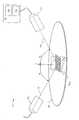
도 1을 참조하면, 계측 시스템(100)이 구조물의 검사 및 분석을 위해 사용된다. 예컨대, 계측 시스템(100)은 웨이퍼(104) 상에 형성된 주기적인 격자(102)의 피쳐를 결정하는데 사용될 수 있다. 이미 설명한 바와 같이, 주기적인 격자(102)는 웨이퍼(104) 상에 형성된 소자에 인접한 것처럼 웨이퍼(104) 상의 시험 영역 내에 형성될 수 있다. 선택적으로, 주기적인 격자(102)는 소자의 작동에 방해되지 않게 소자의 영역 내에 형성되거나 웨이퍼(104) 상의 스크라이브 라인(scribe line)을 따라 형성될 수 있다.Referring to FIG. 1,
도 1에 도시된 것처럼, 계측 시스템(100)은 소스(106) 및 검출기(112)가 구비된 계측장치를 포함할 수 있다. 주기적인 격자(102)는 소스(106)로부터 입사빔(108)에 의해 조명된다. 본 실시예에서, 입사빔(108)은 주기적인 격자(102)의 법선(

또한 계측 시스템(100)은 측정된 회절신호를 수신하고 측정된 회절신호를 분석하도록 구성된 프로세싱 모듈(114)을 포함한다. 하기에서 설명하는 바와 같이, 주기적인 격자(102)의 피쳐는 라이브러리-기반 프로세스 또는 회귀-기반 프로세스를 사용하여 결정될 수 있다. 또한, 다른 선형 또는 비선형 프로파일 추출 기술이 고려된다.
2. 라이브러리-기반 프로세스2. Library-based process
라이브러리-기반 프로세스에서, 측정된 회절신호는 회절신호의 라이브러리와 비교된다. 특히, 라이브러리의 각각의 회절신호는 구조물의 프로파일과 연관된다. 측정된 회절신호와 라이브러리의 회절신호 중 하나가 매칭할 때 또는 측정된 회절 신호와 라이브러리의 회절신호 중 하나의 차이가 미리설정된 또는 매칭기준 내에 있을 때, 라이브러리의 매칭 회절신호와 연관된 프로파일은 구조물의 실제 프로파일을 나타내는 것으로 추정한다. 이 때 구조물의 피쳐는 매칭 회절신호와 연관된 프로파일에 기초하여 결정될 수 있다.In a library-based process, the measured diffraction signal is compared with a library of diffraction signals. In particular, each diffraction signal of the library is associated with a profile of the structure. When the measured diffraction signal and one of the library's diffraction signals match, or when the difference between the measured diffraction signal and one of the library's diffraction signals is within a predetermined or matching criterion, the profile associated with the library's matching diffraction signal is determined. It is assumed to represent the actual profile. In this case, the feature of the structure may be determined based on a profile associated with the matching diffraction signal.
따라서, 다시 도 1을 참조하면, 일 실시예에서, 측정된 회절신호를 얻은 후, 프로세싱 모듈(114)은 측정된 회절신호를 라이브러리(116)에 저장된 회절신호와 비교한다. 라이브러리(116)의 각각의 회절신호는 프로파일과 연관된다. 측정되 회절신호와 라이브러리(116)의 회절신호 중 하나 사이에 매칭이 이루어질 때, 라이브러리(116)의 매칭 회절신호와 연관된 프로파일은 주기적인 격자(102)의 실제 프로파일을 나타내는 것으로 추정될 수 있다.Thus, referring again to FIG. 1, in one embodiment, after obtaining the measured diffraction signal, the
라이브러리(116)에 저장된 프로파일 세트는 파라미터 세트를 이용하여 프로파일을 특정화함으로써 생성될 수 있으며, 다음에 모양과 치수가 바뀐 프로파일을 생성하도록 파라미터 세트를 바꾼다. 파라미터 세트를 이용하여 프로파일을 특정화하는 프로세스는 파라미터화라 불릴 수 있다.The profile set stored in
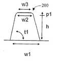
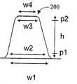
예컨대, 도 2a에 도시된 것처럼, 프로파일(200)이 높이와 폭을 각각 한정하는 파라미터(h1 및 w1)에 의해 특정화될 수 있는 것으로 가정한다. 도 2b 내지 2e에 도시된 것처럼, 프로파일(200)의 추가 모양 및 피쳐가 파라미터의 수를 증가시킴으로써 특정화될 수 있다. 예컨대, 도 2b에 도시된 것처럼, 프로파일(200)은 높이, 하부 폭 및 상부 폭을 각각 한정하는 파라미터(h1, w1 및 w2)에 의해 특정화될 수 있다. 프로파일(200)의 폭은 기준 치수(CD)로 불릴 수 있다. 예컨대, 도 2b에서 파라미터(w1 및 w2)는 프로파일(200)의 하부 기준 치수(CD)와 상부 기준 치수(CD)를 각각 한정하는 것으로 설명될 수 있다. 입사각(AOI), 피치, n&k, 하드웨어 파라미터(예컨대 분극 각도) 등을 포함하는 다양한 타입의 파라미터가 프로파일(200)을 특정화하는데 사용될 수 있다.For example, assume that
상기 설명한 바와 같이, 라이브러리(116) 내에 저장된 프로파일 세트(도 1)는 프로파일을 특정화하는 파라미터를 바꿈으로써 생성될 수 있다. 예컨대, 도 2b를 참조하면, 파라미터(h1,w1 및 w2)를 바꿈으로써, 바뀐 모양과 치수에 대한 프로파일이 생성될 수 있다. 하나, 두 개, 또는 세 개의 파라미터 모두에 대해 서로 바뀔 수 있다.As described above, the profile set (FIG. 1) stored in the
따라서, 매칭 회절신호와 연관된 프로파일의 파라미터는 검사되는 구조물의 피쳐를 결정하는데 사용될 수 있다. 예컨대, 하부 CD에 대응하는 프로파일의 파라미터는 검사되는 구조물의 하부 CD를 결정하는데 사용될 수 있다.Thus, the parameters of the profile associated with the matching diffraction signal can be used to determine the features of the structure being examined. For example, the parameters of the profile corresponding to the bottom CD can be used to determine the bottom CD of the structure being examined.
다시 도 1을 참조하면, 프로파일 세트의 프로파일 및 대응하는 회절신호 및 라이브러리(116)에 저장된 회절신호(즉, 라이브러리(116)의 해상도 및/또는 범위)는 파라미터 세트가 변하는 범위와 증분에 부분적으로 의존한다. 일 실시예에서, 라이브러리(116)에 저장된 프로파일과 회절신호는 실제 구조물로부터 측정된 회절신호를 얻기 전에 생성된다. 따라서, 라이브러리(116)를 생성하는데 사용된 범위와 증분(즉, 범위와 해상도)은 구조물에 대한 제조 프로세스와의 친숙성 및 분산(variance) 범위가 얼마나 존재할 수 있는가에 기초하여 선택될 수 있다. 또한, 라이브러리(116)의 범위 및/또는 해상도는 원자력 현미경(AFM), 주사 전자 현미경(SEM) 등을 이용한 측정과 같이 실험적 측정에 기초하여 선택될 수 있다.Referring back to FIG. 1, the profile of the profile set and the corresponding diffraction signal and the diffraction signal stored in the library 116 (ie, the resolution and / or range of the library 116) are partially dependent on the range and increment in which the parameter set changes. Depends. In one embodiment, the profile and diffraction signal stored in
라이브러리-기반 프로세스에 대한 보다 상세한 설명은 2001년 7월 16일에 출원된 주기적인 격자 회절신호의 라이브러리 생성이란 제목의 미국특허출원 09/907,488호를 참조하면 되며, 상기 특허출원은 그 전체가 본 명세서에 참조로 포함된다.A more detailed description of the library-based process can be found in US Patent Application 09 / 907,488 entitled Library Generation of Periodic Lattice Diffraction Signals, filed Jul. 16, 2001, which is incorporated by reference in its entirety. Incorporated herein by reference.
3. 회귀-기반 프로세스3. Regression-based process
회귀-기반 프로세스에서, 측정된 회절신호는 프로파일에 대한 파라미터 세트(즉, 시험 파라미터)를 이용한 비교 이전에 생성된 회절신호(즉, 시험 회절신호)와 비교된다. 만약 측정된 회절신호와 시험 회절신호가 매칭하지 않거나 측정된 회절신호와 시험 회절신호의 차이가 미리설정되거나 매칭기준 내에 있지 않을 때, 또 다른 시험 회절신호가 또 다른 프로파일에 대한 또 다른 파라미터 세트를 이용하여 생성되며, 그 후에 측정된 회절신호와 새롭게 생성된 시험 회절신호가 비교된다. 측정된 회절신호와 시험 회절신호가 일치하거나 측정된 회절신호와 시험 회절신호가 미리설정되거나 매칭기준 내에 있을 때, 매칭 시험 회절신호와 연관된 프로파일은 구조물의 실제 프로파일을 나타내는 것으로 추정된다. 이 때 매칭 시험 회절신호와 연관된 프로파일은 검사되는 구조물의 피쳐를 결정하는데 사용될 수 있다.In a regression-based process, the measured diffraction signal is compared with the diffraction signal (ie test diffraction signal) generated before comparison using the parameter set (ie test parameter) for the profile. If the measured diffraction signal and the test diffraction signal do not match, or the difference between the measured diffraction signal and the test diffraction signal is not preset or within the matching criteria, another test diffraction signal generates another parameter set for another profile. And a newly generated test diffraction signal is compared with the measured diffraction signal. When the measured diffraction signal and the test diffraction signal coincide or when the measured diffraction signal and the test diffraction signal are preset or within the matching criteria, the profile associated with the matching test diffraction signal is assumed to represent the actual profile of the structure. The profile associated with the matching test diffraction signal can then be used to determine the features of the structure being inspected.
따라서, 도 1을 다시 참조하면, 일 실시예에서, 프로세싱 모듈(114)은 프로파일에 대한 시험 회절신호를 생성할 수 있고, 측정된 회절신호를 시험 회절신호와 비교한다. 상기 설명한 바와 같이, 만약 측정된 회절신호와 시험 회절신호가 매칭하지 않거나 측정된 회절신호와 시험 회절신호와의 차이가 미리설정되거나 매칭기준 내에 있지 않으며, 프로세싱 모듈(114)은 또 다른 프로파일에 대한 또 다른 시험 회절신호를 반복하여 생성할 수 있다. 일 실시예에서, 연속적으로 생성된 시험 회절신호는 시뮬레이팅된 어닐링을 포함하는 전체 최적화 기술 및 최대 경사 알고리즘(steepest descent algorithm)을 포함한 국부적인 최적화 기술과 같은 최적화 알고리즘을 이용하여 생성될 수 있다.Thus, referring again to FIG. 1, in one embodiment, the
일 실시예에서, 시험 회절신호와 프로파일은 라이브러리(116)(즉, 다이내믹 라이브러리) 내에 저장될 수 있다. 라이브러리(116) 내에 저장된 시험 회절신호와 프로파일은 측정된 회절신호를 매칭시키는데 연속적으로 사용될 수 있다. 선택적으로, 라이브러리(116)는 계측 시스템(100)에서 생략될 수 있다.In one embodiment, the test diffraction signal and profile may be stored in library 116 (ie, a dynamic library). The test diffraction signal and profile stored in the
회귀-기반 프로세스에 대한 보다 상세한 설명은 2001년 8월 6일에 출원된 회귀-기반 라이브러리 생성 프로세스에 의한 다이내믹 학습 방법 및 시스템이란 제목의 미국특허출원 제09/923,578호를 참조하면 되며, 상기 특허출원 명세서 전체는 본 명세서에 참조로 포함된다.For a more detailed description of the regression-based process, see US patent application Ser. No. 09 / 923,578 entitled Dynamic Learning Methods and Systems by Regression-Based Library Generation Process, filed Aug. 6, 2001. The entire application specification is incorporated herein by reference.
4. 기계학습시스템4. Machine Learning System
도 1을 참조하면, 일 실시예에서, 라이브러리-기반 프로세스 및/또는 회귀-기반 프로세스에 사용된 회절신호는 역-전파(back-propagation), 방사기반 함수(radial basis function), 지지 벡터, 커널 회귀(kernel regression) 등을 이용한 기계학습시스템(118)을 사용하여 생성된다. 기계학습시스템과 알고리즘에 대한 보다 상세한 설명은 1999년에 발간된 Prentice Hall의 Simon Hykin 저 "신경망"을 참조하면 되며, 상기 내용은 그 전체가 본 명세서에서 참조로 포함된다.Referring to FIG. 1, in one embodiment, the diffraction signals used in the library-based and / or regression-based processes are back-propagation, radial basis function, support vector, kernel. Generated using
본 실시예에서, 기계학습시스템(118)은 입력으로서 프로파일을 수신하고 출력으로서 회절신호를 생성한다. 비록 도 1에서 기계학습시스템(118)이 프로세싱 모듈(114)의 부품으로서 도시되었지만, 기계학습시스템(118)은 독립된 모듈일 수 있다. 더구나, 기계학습시스템(118)이 라이브러리-기반 프로세스의 일부로서 사용될 때, 라이브러리(116)의 회절신호는 기계학습시스템(118)에 의해 미리 생성될 수 있다. 이와 같이, 기계학습시스템(118)은 프로세싱 모듈(114)에 연결되지 않는 독립된 모듈일 수 있다. 반대, 기계학습시스템(118)이 프로세싱 모듈(114)의 부품이라기 보다 독립된 모듈인 때에도 기계학습시스템(118)은 프로세싱 모듈(114)에 연결된다.In this embodiment,
도 3을 참조하면, 일 실시예에서, 기계학습시스템은 역-전파 알고리즘을 이용하는 신경망(300)이다. 신경망(300)은 입력층(302), 출력층(304) 및 입력층(302)과 출력층(304) 사이의 은닉층(hidden layer)(306)을 포함한다. 입력층(302)과 은닉층(306)은 링크(308)를 이용하여 연결된다. 은닉층(306)과 출력층(304)은 링크(310)를 이용하여 연결된다. 그러나, 신경망(300)은 다양한 구성으로 연결된 임의 수의 층들을 포함할 수 있다.Referring to FIG. 3, in one embodiment, the machine learning system is a
도 3에 도시된 바와 같이, 입력층(302)은 하나 이상의 입력 노드(312)를 포함한다. 본 실시예에서, 입력층(302)의 입력 노드(312)는 신경망(300)으로 입력될 프로파일의 파라미터에 대응한다. 따라서, 입력 노드(312)의 수는 프로파일을 특정화하는데 사용된 파라미터의 수에 대응한다. 예컨대, 만약 프로파일이 2 개의 파라미터(예컨대, 상부 및 하부 폭)을 이용하여 특정화된다면, 입력층(302)은 2 개 의 입력 노드(312)를 포함하며, 2 개의 입력 노드 중 제 1 입력노드(312)는 제 1 파라미터(예컨대, 상부 폭)에 대응하고 제 2 입력 노드(312)는 제 2 파라미터(예컨대, 하부 폭)에 대응한다.As shown in FIG. 3,
신경망(300)에서, 출력층(304)은 하나 이상의 출력 노드(314)를 포함한다. 본 실시예에서, 각각의 출력 노드(314)는 선형 함수이다. 그러나, 각각의 출력 노드(314)는 다양한 타입의 함수일 수 있다. 또한, 본 실시예에서, 출력층(304)의 출력 노드(314)는 신경망(300)으로부터 출력된 회절신호의 치수에 대응한다. 따라서, 출력 노드(314)의 수는 회절신호를 특정화하는데 사용된 치수의 수에 대응한다. 예컨대, 회절신호가 예컨대 5개의 상이한 파장에 대응하는 5개의 치수를 이용하여 특정화된다면, 출력층(304)은 5개의 출력 노드(314)를 포함하며, 5개의 출력 노드들 중 제 1 출력 노드(314)는 제 1 치수(예컨대 제 1 파장)에 대응하고, 제 2 출력 노드(314)는 제 2 치수(예컨대, 제 2 파장)에 대응한다.In
신경망(300)에서, 은닉층(306)은 하나 이상의 은닉 노드(316)를 포함한다. 본 실시예에서, 각각의 은닉 노드(316)는 S자 전달 함수 또는 방사기반 함수이다. 그러나, 각각의 은닉 노드(316)는 다양한 타입의 함수일 수 있다. 또한, 본 실시예에서, 은닉 노드(316)의 수는 출력 노드(314)의 수에 기초하여 결정된다. 특히, 은닉 노드(316)(m)의 수는 미리결정된 비율(r=m/n)만큼 출력 노드(314)(n)의 수와 관련한다. 예컨대, r=10인 경우, 각각의 출력 노드(314)에 대해 10개의 은닉 노드(316)가 존재한다. 그러나, 미리결정된 비율은 출력 노드(314)의 수 대 은닉 노드(316)의 수의 비율(즉, r=n/m)일 수 있다. 또한, 신경망(300)의 은닉 노드(316)의 수는 은닉 노드(316)의 최초 수가 미리결정된 비율에 기초하여 결정된 후에 조절될 수 있다. 게다가, 신경망(300)의 은닉 노드(316)의 수는 미리결정된 비율에 기초하기 보다는 실험 및/또는 경험에 기초하여 결정될 수 있다.In
회절신호를 생성하기 위해 기계학습시스템을 사용하기 이전에, 기계학습시스템이 훈련된다. 도 4를 참조하면, 기계학습시스템을 훈련시키기 위한 예시적인 프로세스(400)가 도시되어 있다. 예시적인 프로세스(400)에서, 기계학습시스템은 훈련 입력 데이터 세트 및 훈련 출력 데이터 세트를 이용하여 훈련되는데, 훈련 입력 데이터 세트의 입력 데이터는 입력 및 출력 데이터 쌍을 형성하기 위해 훈련 출력 데이터 세트의 대응 출력 데이터를 갖는다.Before using the machine learning system to generate a diffraction signal, the machine learning system is trained. 4, an
단계 402에서, 훈련 입력 데이터 세트가 얻어진다. 본 실시예에서, 훈련 입력 데이터는 프로파일 세트를 포함한다. 상기 설명한 바와 같이, 프로파일은 파라미터 세트를 이용하여 특정화된다. 프로파일의 범위는 단독으로 또는 조합되어 프로파일을 특정화시키는 하나 이상의 파라미터를 바꿈으로써 생성될 수 있다. 생성될 전체 프로파일 범위는 검사될 구조물의 실제 프로파일의 예측된 변화 범위에 기초하여 결정되며, 이는 실험적으로 또는 경험을 통해 결정된다. 예컨대, 검사될 구조물의 실제 프로파일은 x1과 x2 사이에서 변할 수 있는 하부 폭을 갖는 것으로 예측되면, 프로파일의 전체 범위는 x1과 x2 사이의 하부 폭에 대응하는 파라미터를 바꿈으로써 생성될 수 있다.In
일 실시예에서, 기계학습시스템을 훈련시키는데 사용된 프로파일 세트는 생성될 전체 프로파일 범위에서 선택된다. 특히, 훈련 데이터 세트는 전체 프로파일 범위의 임의적인 샘플링을 이용하여 선택된다. 시스템 샘플링, 랜덤 샘플링과 시스템 샘플링의 조합 등과 같은 다양한 샘플링 기술이 훈련 데이터 세트를 선택하는데 사용될 수 있다.In one embodiment, the profile set used to train the machine learning system is selected from the full range of profiles to be generated. In particular, the training data set is selected using an arbitrary sampling of the full profile range. Various sampling techniques can be used to select a training data set, such as system sampling, a combination of random sampling and system sampling.
본 실시예에서, 생성될 전체 프로파일 범위는 두 개 이상의 부분으로 분할 된다. 기계학습시스템은 각각의 부분에 대해 구성되고 훈련된다. 예컨대, 전체 범위는 제 1 부분 및 제 2 부분으로 분할되는 것으로 가정한다. 따라서, 본 예에서, 제 1 기계학습시스템은 제 1 부분에 대해 구성되고 훈련되며, 제 2 기계학습시스템은 제 2 부분에 대해 구성되고 훈련된다. 전체 범위를 부분화시키고 다수의 기계학습시스템을 이용하는 것은 병렬 프로세싱이 사용될 수 있다는(예를 들어, 두 개의 기계학습시스템이 병렬로 훈련되고 사용될 수 있다는) 장점을 갖는다. 또 다른 장점은 각각의 기계학습시스템이 전체 범위에 대해 하나의 기계학습시스템을 이용하는 것보다는 각각의 부분에 대하여 보다 정확할 수 있다는 것이다. 특히, 전체 범위에 대해 훈련된 하나의 기계학습시스템은 기계학습시스템의 정확성을 감소시킬 수 있는 국부적인 최소값에 민감할 수 있다.In this embodiment, the entire profile range to be created is divided into two or more parts. Machine learning systems are configured and trained for each part. For example, assume that the entire range is divided into a first portion and a second portion. Thus, in this example, the first machine learning system is configured and trained for the first portion, and the second machine learning system is configured and trained for the second portion. Segmenting the full range and using multiple machine learning systems has the advantage that parallel processing can be used (eg, two machine learning systems can be trained and used in parallel). Another advantage is that each machine learning system can be more accurate for each part than using one machine learning system for the entire range. In particular, one machine learning system trained over the entire range may be sensitive to local minimum values that may reduce the accuracy of the machine learning system.
전체 범위가 부분화되는 경우, 부분은 동일한 사이즈이거나 변하는 사이즈일 수 있다. 부분이 변하는 사이즈인 경우, 부분의 사이즈는 부분 내의 데이터의 밀도에 기초하여 결정될 수 있다. 예컨대, 적은 밀도의 부분은 높은 밀도의 부분 보다 클 수 있다. 부분의 수와 사이즈는 적용에 따라 바뀔 수 있다.If the whole range is subdivided, the portions may be the same size or of varying sizes. If the portion is of varying size, the size of the portion may be determined based on the density of data in the portion. For example, the less dense portion may be larger than the higher dense portion. The number and size of parts may vary depending on the application.
단계 404에서, 훈련 출력 데이터 세트가 얻어진다. 본 실시예에서, 훈련 출력 데이터는 회절신호 세트를 포함한다. 훈련 출력 데이터로서 사용된 회절신호 세트의 회절신호는 훈련 입력 데이터로서 사용된 프로파일 세트의 프로파일에 해당한다. 회절신호 세트의 각각의 회절신호는 엄밀한 결합파 분석(RCWA), 적분법, 프레넬 방법(Fresnel method), 유한 분석법, 구조 분석법(modal analysis) 등과 같은 모델링 기술을 이용한 프로파일 세트의 각각의 프로파일에 기초하여 생성될 수 있다. 선택적으로, 회절신호 세트의 각각의 회절신호는 타원계, 반사계, 원자력 현미경(AFM), 주사 전자 현미경(SEM) 등과 같은 계측장치를 이용하여 회절신호를 측정하는 것처럼 실험 기술을 이용하여 프로파일 세트의 각각의 프로파일에 기초하여 생성될 수 있다. 따라서, 프로파일 세트로부터의 프로파일과 회절신호 세트로부터의 대응하는 회절신호는 프로파일/회절신호 쌍을 형성한다. 비록 프로파일/회절신호 쌍의 프로파일 및 회절신호 간의 일대일 대응이 존재하지만, 프로파일/회절신호 쌍의 프로파일과 회절신호 사이에 분석적 또는 수치적 공지 관계일 필요는 없다.In
일 실시예에서, 기계학습시스템을 훈련시키기 위해 회절신호 세트를 사용하기 전에, 회절신호 세트는 주성분 분석법(PCA:principle component analysis)을 이용하여 변환된다. 특히, 회절신호는 다수의 상이한 파장과 같은 다수의 치수를 이용하여 특정화될 수 있다. 회절신호 세트를 변화시키기 위해 PCA를 이용함으로써, 회절신호는 비상관된 치수로 변환되고, 비상관된 치수의 공간은 원래 치수의 공간보다 작다. 기계학습시스템이 훈련된 후에, 회절신호는 다시 변환된다.In one embodiment, prior to using the diffraction signal set to train the machine learning system, the diffraction signal set is transformed using principal component analysis (PCA). In particular, the diffraction signal can be specified using a number of dimensions, such as a number of different wavelengths. By using the PCA to change the set of diffraction signals, the diffraction signal is converted into uncorrelated dimensions, and the space of the uncorrelated dimension is smaller than the space of the original dimension. After the machine learning system is trained, the diffraction signal is converted again.
본 실시예에서, 회절신호의 치수는 두 개 이상의 부분으로 분할될 수 있다. 기계학습시스템은 각각의 부분에 대해 구성되고 훈련된다. 예컨대, 치수는 제 1 부분 및 제 2 부분으로 분할된다고 가정한다. 따라서, 이러한 예에서, 제 1 기계학습시스템은 제 1 부분에 대해 구성되고 훈련되며, 제 2 기계학습시스템은 제 2 부분에 대해 구성되고 훈련된다. 즉, 치수를 부분화시키고 다수의 기계학습시스템을 이용하는 것은 병렬 프로세싱이 이용될 수 있다는(예컨대, 두 개의 기계학습시스템이 병렬로 훈련되고 사용될 수 있다는) 장점을 갖는다. 또 다른 장점은 각각의 기계학습시스템은 하나의 기계학습시스템을 이용하는 것보다 각각의 부분에 대해 보다 정확할 수 있다는 것이다.In this embodiment, the dimension of the diffraction signal can be divided into two or more portions. Machine learning systems are configured and trained for each part. For example, assume that the dimension is divided into a first portion and a second portion. Thus, in this example, the first machine learning system is configured and trained for the first portion, and the second machine learning system is configured and trained for the second portion. That is, segmenting dimensions and using multiple machine learning systems has the advantage that parallel processing can be used (eg, two machine learning systems can be trained and used in parallel). Another advantage is that each machine learning system can be more accurate for each part than using one machine learning system.
단계 406에서, 훈련 입력 데이터로서 사용된 프로파일 세트로부터의 프로파일에 있어서, 회절신호는 기계학습시스템을 이용하여 생성된다. 단계 408에서, 생성된 회절신호는 프로파일에 해당하는 회절신호 세트의 회절신호와 비교된다. 회절신호들 간의 차이가 원하는 또는 미리결정된 에러 마진 내에 있지 않는 경우, 단계 406 과 단계 408이 훈련 입력 데이터로서 사용된 프로파일 세트의 또 다른 프로파일을 이용하여 반복된다. 단계 410에서, 회절신호들 간의 차이가 원하는 또는 미리결정된 에러 마진 내에 있을 때, 훈련 프로세스가 종료된다.In
훈련 프로세스(400)는 기울기 하강, 선형 프로그래밍, 2차 프로그래밍, 시뮬레이팅 어닐링, 마콰트-레벤베레그 알고리즘(Marquardt-Levenberg algorithm) 등과 같은 최적화 기술의 사용을 포함할 수 있다. 또한, 훈련 프로세스 400은 배치(batch) 프로세스로서 수행될 수 있다. 배치 프로세스의 보다 상세한 설명은 상기에서 인용된 사이먼 호이킨의 "신경망"을 참조하면 된다.
또한, 도 4에 도시된 훈련 프로세스는 역-전파 알고리즘을 예시한다. 그러나, 방사기반 네트워크, 지지 벡터, 커널 회귀 등과 같은 다양한 훈련 알고리즘이 사용될 수 있다.In addition, the training process shown in FIG. 4 illustrates a back-propagation algorithm. However, various training algorithms can be used, such as radiation-based networks, support vectors, kernel regression, and the like.
도 5를 참조하면, 기계학습시스템을 시험하기 위한 예시적인 프로세스(500)가 도시되어 있다. 일 실시예에서, 기계학습시스템이 훈련된 뒤에, 기계학습시스템은 적절히 훈련되었는지를 확인하기 위해 시험될 수 있다. 그러나, 이러한 시험 프로세스는 일부 어플리케이션에서는 생략될 수 있다.Referring to FIG. 5, an
단계 502에서, 시험 입력 데이터 세트가 얻어진다. 단계 504에서, 시험 출력 데이터 세트가 얻어진다. 본 실시예에서, 시험 입력 데이터는 프로파일 세트를 포함하고, 시험 출력 데이터는 회절신호 세트를 포함한다. 시험 입력 데이터 세트와 시험 출력 데이터 세트는 상기 훈련 프로세스에서 설명한 것과 동일한 프로세스와 기술을 이용하여 얻어질 수 있다. 시험 입력 데이터 세트와 시험 출력 데이터 세트는 동일하거나 시험 입력 데이터와 시험 출력 데이터의 하위세트일 수 있다. 선택적으로, 시험 입력 데이터 세트와 시험 출력 데이터 세트는 시험 입력 데이터 및 시험 출력 데이터보다 상이할 수 있다.In
단계 506에서, 시험 입력 데이터로서 사용된 프로파일 세트의 프로파일에 대해, 회절신호는 기계학습시스템을 이용하여 생성된다. 단계 508에서, 생성된 회절신호는 프로파일에 대응하는 시험 출력 데이터에서 회절신호 세트의 회절신호와 비교된다. 단계 510에서, 회절신호들 간의 차이가 원하는 또는 미리결정된 에러 마진 내에 있지 않은 경우, 기계학습시스템은 다시 훈련된다. 기계학습시스템이 다시 훈련되는 경우, 훈련 프로세스는 조정될 수 있다. 예컨대, 훈련 입력 및 출력 변수의 선택과 수가 조정될 수 있다. 또한, 기계학습시스템이 조정될 수 있다. 예컨대, 기계학습시스템이 상기 설명한 것처럼 신경망인 경우, 은닉 노드의 수는 조정될 수 있다. 단계 512에서, 회절신호들 간의 차이가 원하는 또는 미리결정된 에러 마진 내에 있는 경우, 시험 프로세스는 종료된다.In
경험적 위험 최소화(ERM:Empirical Risk Minimization) 기술은 훈련된 기계학습시스템이 얼마나 우수하게 새로운 입력을 생성할 수 있는가를 한정하는데 사용될 수 있다. ERM에 대한 보다 상세한 설명은 1998년 9월에 Wiley-Interscience에서 출간한 블라디미르 엔. 배프니크(Vladimir N, Vapnik)의 "통계적 학습 이론"을 참조하면 되며, 상기 문헌은 그 전체가 본 명세서에 참조로 포함된다.Empirical Risk Minimization (ERM) techniques can be used to limit how well trained machine learning systems can generate new inputs. For more information on ERM, see Vladimir N., published in Wiley-Interscience in September 1998. See, for example, "Statistical Learning Theory" by Vladimir N, Vapnik, which is incorporated herein by reference in its entirety.
기계학습시스템이 훈련되고 시험된 후에, 기계학습시스템은 반도체 위이퍼 상에 형성된 구조물의 분석에 사용하기 위한 회절신호를 생성하는데 사용될 수 있다. 즉, 시험 프로세스는 일부 어플리케이션에서 생략될 수 있다.After the machine learning system has been trained and tested, the machine learning system can be used to generate diffraction signals for use in the analysis of structures formed on semiconductor wipers. That is, the test process may be omitted in some applications.
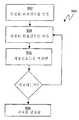
도 6을 참조하면, 반도체 웨이퍼 상에 형성된 구조물을 검사하기 위해 기계학습시스템을 이용하기 위한 예시적인 프로세스(600)가 도시되어 있다. 단계 602에서, 측정된 회절신호는 기계학습시스템을 이용하여 얻어진다. 단계 604에서, 생성된 회절신호는 기계학습시스템을 이용하여 얻어진다. 단계 606에서, 회절신호들은 비교된다. 단계 608에서, 구조물의 피쳐는 측정된 회절신호와 생성된 회절신호의 비교에 기초하여 결정된다.Referring to FIG. 6, an
특히, 상기 설명한 것처럼, 생성된 회절신호에 대응하는 프로파일은 생성된 회절신호를 생성하기 위한 기계학습시스템에 대한 입력으로서 사용된다. 프로파일은 하나 이상의 파라미터에 의해 특정화된다. 따라서, 생성된 회절신호가 매칭기준 내에서 측정된 회절신호와 매칭될 때, 프로파일 및 프로파일을 특정화하는 하나 이상의 파라미터는 구조물의 피쳐를 결정하는데 사용될 수 있다.In particular, as described above, the profile corresponding to the generated diffraction signal is used as an input to the machine learning system for generating the generated diffraction signal. Profiles are specified by one or more parameters. Thus, when the generated diffraction signal matches the diffraction signal measured within the matching criteria, the profile and one or more parameters specifying the profile can be used to determine the features of the structure.
도 7을 참조하면, 라이브러리-기반 프로세스에서 기계학습시스템을 이용하기 위한 예시적인 프로세스(700)가 도시되어 있다. 단계 702에서, 회절신호의 라이브러리는 기계학습시스템을 이용하여 생성된다. 특히, 회절신호의 라이브러리는 프로파일의 범위를 기계학습시스템에 입력시킴으로써 생성된다. 단계 704에서, 측정된 회절신호는 타원계, 반사계 등과 같은 계측장치를 이용하여 얻어진다. 단계 706에서, 측정된 회절신호는 기계학습시스템을 이용하여 생성된 회절신호의 라이브러리의 회절신호와 비교된다. 단계 708에서, 구조물의 피쳐는 회절신호의 라이브러리의 매칭 회절신호에 대응하는 프로파일을 이용하여 결정된다.Referring to FIG. 7, an
도 8을 참조하면, 라이브러리-기반 시스템의 기계학습시스템을 이용하기 위한 예시적인 시스템(800)이 도시되어 있다. 도 8에 도시된 것처럼, 라이브러리(116)는 기계학습시스템(118)을 이용하여 생성된다. 라이브러리(116)는 타원계, 반사계 등과 같은 계측장치(802)로부터 얻어진 측정된 회절신호와 라이브러리(116)의 회절신호를 비교하기 위한 프로세싱 모듈(114)에 사용된다. 비록 기계학습시스템(118)도 8의 독립 유닛으로 도시되었지만, 기계학습시스템(118)은 프로세싱 모듈(114)의 부품으로서 통합될 수 있다. 또한, 기계학습시스템(118)은 예컨대 네트워크 연결을 통해 라이브러리(116)를 프로세싱 모듈(114)로 전송하기 위해 프로세싱 모듈(114)에 연결될 수 있다. 또한, 라이브러리(116)는 휴대용 저장 매체에 저장되고 물리적으로 프로세싱 모듈(114)에 전송될 수 있다.Referring to FIG. 8, an
게다가, 도 8에 도시된 것처럼, 프로세싱 모듈(114)은 하나 이상의 제작 단계들을 수행하도록 구성된 반도체 제조 유닛(804)에 결합될 수 있다. 그러나, 계측 시스템은 반도체 제작 유닛(804)에 통합되는 것에 부가하여 독립된 시스템으로서 작동할 수 있다.In addition, as shown in FIG. 8, the
도 9를 참조하면, 회귀-기반 프로세스에서 기계학습시스템을 사용하기 위한 예시적인 프로세스(900)가 도시되어 있다. 단계 902에서, 측정된 회절신호는 타원계, 반사계, 원자력 현미경(AFM), 주사 전자 현미경(SEM) 등과 같은 계측장치를 이용하여 얻어진다. 단계 904에서, 생성된 회절신호는 기계학습시스템을 이용하여 얻어진다. 단계 906에서, 두 개의 회절신호가 비교된다. 두 개의 회절신호가 미리결정된 매칭기준 내에서 매칭하지 않는 경우, 단계 904와 단계 906은 단계 904에서 생성된 또 다른 회절신호를 이용하여 반복된다. 이러한 프로세스는 생성된 회절신호와 측정된 회절신호가 미리결정된 매칭기준 내에서 매칭하는 것을 나타내는 매칭이 발견될 때까지 반복된다. 단계 908에서, 만약 두 개의 회절신호가 미리결정된 매칭기준 내에서 매칭한다면, 매칭 회절신호에 대응하는 프로파일은 검사되는 구조물의 실제 프로파일에 대응하는 것으로 가정한다. 따라서, 프로파일과 프로파일을 특정화하는 파라미터는 구조물의 피쳐를 결정하는데 사용될 수 있다.Referring to FIG. 9, an
도 10을 참조하면, 회귀-기반 시스템에서 기계학습시스템을 이용하기 위한 예시적인 시스템(1000)이 도시되어 있다. 도 10에 도시된 것처럼, 최적화기(1002) 는 계측장치(802)로부터 입력으로서 측정된 회절신호를 수신한다. 최적화기(1002)는 기계학습시스템(118)으로부터 입력으로서 생성된 회절신호를 수신한다. 최적화기(1002)는 생성된 회절신호와 측정된 회절신호를 비교한다. 생성된 회절신호와 측정된 회절신호가 매칭할 때, 최적화기(1002)는 매칭하는 생성된 회절신호에 대응하는 프로파일을 출력한다. 생성된 회절신호와 측정된 회절신호가 미리결정된 매칭기준 내에서 매칭하지 않을 때, 최적화기(1002)는 또 다른 회절신호를 생성하기 위하여 신호를 기계학습시스템(118)으로 출력한다. 이러한 프로세스는 생성된 회절신호와 측정된 회절신호가 미리결정된 매칭기준 내에서 매칭하는 것을 의미하는 매칭이 발견될 때까지 반복된다.Referring to FIG. 10, an
일 실시예에서, 최적화 기술은 매칭에 도달하는데 필요한 반복 횟수를 감소시키는데 사용된다. 특히, 최적화 문제의 목적은 최적의 솔루션이 비용 함수와 관련시켜 한정되는 여러 가능한 솔루션 중에서 최적의 솔루션을 찾아내는 것이다. 즉, 주어진 측정 규준(metric)에서 주어진 문제에 대해, 최소의 비용을 갖는 솔루션을 찾아내는 작업이다. 따라서, 본 실시예에서, 주어진 측정 회절신호와 관련하여 (주어진 비용 측정 규준 하에서) 최소의 비용을 산출하는 대응하는 회절신호를 갖는 프로파일을 찾아내는 작업이다. 기울기 하강, 선형 프로그래밍, 2차 프로그래밍, 시뮬레이팅 프로그래밍, 마콰트-레벤베레그 알고리즘 등과 같이, 크게 두 개의 카테고리(즉, 전체적 및 국부적)로 분류되는 다양한 최적화 기술이 알려져 있고 사용된다. 전체적 및 국부적 최적화 기술에 대한 보다 상세한 설명은 캠브리지에서 제2판으로 출간한, 윌리엄 에이취. 프레스(William H. Press), 소울 에이. 토이 콜스키(Saul A. Teukolsky), 윌리암 티. 베터링(William T. Vetterling) 및 브라이언 피. 플래너리(Brian P. Flannery)의 "Numerical Recipes in C"를 참조하면 되며, 상기 문헌은 본 명세서에 참조로 포함된다.In one embodiment, optimization techniques are used to reduce the number of iterations needed to reach a match. In particular, the purpose of the optimization problem is to find the optimal solution among a number of possible solutions in which the optimal solution is limited in terms of the cost function. That is, finding a solution with the least cost for a given problem in a given metric. Thus, in this embodiment, the task is to find a profile with a corresponding diffraction signal that yields a minimum cost (under given cost measurement criteria) with respect to a given measurement diffraction signal. Various optimization techniques are known and used that fall into two broad categories (ie, global and local), such as gradient descent, linear programming, quadratic programming, simulating programming, the Maquat-Levenbereg algorithm. For a more detailed description of global and local optimization techniques, see William H., second edition of Cambridge. William H. Press, Soul A. Saul A. Teukolsky, William T. William T. Vetterling and Brian P. See " Numerical Recipes in C " by Brian P. Flannery, which is incorporated herein by reference.
상기 설명한 바와 같이, 회절신호의 라이브러리는 회귀-기반 프로세스의 일부로서 생성될 수 있다. 특히, 생성된 회절신호와 측정된 회절신호가 매칭기준 내에서 매칭하는 것을 의미하는 매칭이 이루어졌을 때, 회절신호의 라이브러리는 매칭 프로파일 주위에서 생성될 수 있다. 일반적으로, 회귀-기반 프로세스의 일부로서 생성된 회절신호의 라이브러리는 상기 설명한 라이브러리-기반 프로세스의 일부로서 생성된 라이브러리보다 작다.As described above, a library of diffraction signals can be generated as part of a regression-based process. In particular, when a match is made that means that the generated diffraction signal and the measured diffraction signal match within a matching criterion, a library of diffraction signals can be generated around the matching profile. In general, the library of diffraction signals generated as part of a regression-based process is smaller than the library generated as part of the library-based process described above.
또한, 회귀-기반 프로세스의 일부로서 생성된 회절신호의 라이브러리와 상기 설명한 라이브러리-기반 프로세스의 일부로서 생성된 라이브러리는 솔루션이 라이브러리의 두 개의 엔트리 사이에서 유도되는 보간(interpolation) 프로세스에 사용될 수 있다. 보간 프로세스에 대한 보다 상세한 설명은 2002년 2월 12일자로 출원된 "PROFILE REFINEMENT FOR INTEGRATED CIRTCUIT METROLOGY"란 제목의 미국특허출원 10/075,904호에 개시되어 있으며, 상기 미국특허출원은 그 전체가 본 명세서에 참조로 포함된다.In addition, the library of diffraction signals generated as part of the regression-based process and the library generated as part of the library-based process described above can be used in an interpolation process in which a solution is derived between two entries of the library. A more detailed description of the interpolation process is disclosed in US Patent Application No. 10 / 075,904 entitled “PROFILE REFINEMENT FOR INTEGRATED CIRTCUIT METROLOGY,” filed Feb. 12, 2002, which is incorporated herein in its entirety. Included by reference.
본 발명의 특정 실시예에 대한 상기 설명은 예시와 설명을 위한 것으로 제시되었다. 이러한 실시예는 본 발명을 한정하고자 하는 것이 아니며 본 발명의 다양한 수정과 변화가 상기 설명을 참조하여 이루어질 수 있다.The foregoing descriptions of specific embodiments of the present invention have been presented for purposes of illustration and description. These embodiments are not intended to limit the invention, and various modifications and changes of the present invention can be made with reference to the above description.
예컨대, 도 1을 참조하면, 상기 설명한 것처럼, 기계학습시스템(118)은 원자력 현미경(AFM), 주사 전자 현미경(SEM) 등과 같은 비광학적 계측장치, 또는 광학적 및 비광학적 계측장치의 조합을 이용하여 작동하도록 구성될 수 있다. 따라서, 기계학습시스템(118)은 사용된 계측장치의 타입에 대응하는 다양한 타입의 회절신호를 생성할 수 있다. 예컨대, 계측장치가 SEM일 때, 기계학습시스템(118)에 의해 생성된 회절신호는 2차원 이미지 또는 SEM 궤적(trace)와 같은 SEM 신호이다.For example, referring to FIG. 1, as described above, the
또한, 생성된 회절신호는 계측장치에 의해 사용된 신호의 특정 기능을 포함할 수 있다. 예컨대, 훈련 프로세스 동안, 회절신호의 다양한 차수의 도함수(예컨대, 1차, 2차, ...nth 도함수)가 훈련 프로세스를 최적화하기 위한 마콰트-레벤베레그 알고리즘의 일부로서 사용될 수 있다.In addition, the generated diffraction signal may include a particular function of the signal used by the metrology device. For example, during the training process, various orders of derivatives (e.g., first, second, ... nth derivatives) of the diffraction signal may be used as part of the Maquat-Levenbereg algorithm to optimize the training process.
Claims (29)
Translated fromKoreanApplications Claiming Priority (3)
| Application Number | Priority Date | Filing Date | Title |
|---|---|---|---|
| US10/608,300US20040267397A1 (en) | 2003-06-27 | 2003-06-27 | Optical metrology of structures formed on semiconductor wafer using machine learning systems |
| US10/608,300 | 2003-06-27 | ||
| PCT/US2004/020682WO2005003911A2 (en) | 2003-06-27 | 2004-06-25 | Optical metrology of structures formed on semiconductor wafers using machine learning systems |
Publications (2)
| Publication Number | Publication Date |
|---|---|
| KR20060033740A KR20060033740A (en) | 2006-04-19 |
| KR101059427B1true KR101059427B1 (en) | 2011-08-25 |
Family
ID=33540544
Family Applications (1)
| Application Number | Title | Priority Date | Filing Date |
|---|---|---|---|
| KR1020057024949AExpired - LifetimeKR101059427B1 (en) | 2003-06-27 | 2004-06-25 | Optical Measurement of Structures Formed on Semiconductor Wafers Using Machine Learning Systems |
Country Status (6)
| Country | Link |
|---|---|
| US (2) | US20040267397A1 (en) |
| JP (1) | JP4589315B2 (en) |
| KR (1) | KR101059427B1 (en) |
| CN (1) | CN100418083C (en) |
| DE (1) | DE112004001001T5 (en) |
| WO (1) | WO2005003911A2 (en) |
Cited By (3)
| Publication number | Priority date | Publication date | Assignee | Title |
|---|---|---|---|---|
| WO2021101069A1 (en)* | 2019-11-18 | 2021-05-27 | 고려대학교 산학협력단 | Apparatus and method for testing semiconductor device by using machine learning model |
| KR20220122111A (en)* | 2021-02-26 | 2022-09-02 | 김이경 | Method and device for designing structure for controlling wave distribution |
| KR20240099634A (en) | 2022-12-22 | 2024-07-01 | 한국화학연구원 | An artificial intelligence-based atomic structure optimization method for inorganic materials |
Families Citing this family (161)
| Publication number | Priority date | Publication date | Assignee | Title |
|---|---|---|---|---|
| US7330279B2 (en)* | 2002-07-25 | 2008-02-12 | Timbre Technologies, Inc. | Model and parameter selection for optical metrology |
| US7394554B2 (en)* | 2003-09-15 | 2008-07-01 | Timbre Technologies, Inc. | Selecting a hypothetical profile to use in optical metrology |
| US7224471B2 (en)* | 2003-10-28 | 2007-05-29 | Timbre Technologies, Inc. | Azimuthal scanning of a structure formed on a semiconductor wafer |
| US7523076B2 (en)* | 2004-03-01 | 2009-04-21 | Tokyo Electron Limited | Selecting a profile model for use in optical metrology using a machine learning system |
| US7388677B2 (en)* | 2004-03-22 | 2008-06-17 | Timbre Technologies, Inc. | Optical metrology optimization for repetitive structures |
| US20050275850A1 (en)* | 2004-05-28 | 2005-12-15 | Timbre Technologies, Inc. | Shape roughness measurement in optical metrology |
| US7065423B2 (en)* | 2004-07-08 | 2006-06-20 | Timbre Technologies, Inc. | Optical metrology model optimization for process control |
| US7566181B2 (en)* | 2004-09-01 | 2009-07-28 | Tokyo Electron Limited | Controlling critical dimensions of structures formed on a wafer in semiconductor processing |
| US7171284B2 (en) | 2004-09-21 | 2007-01-30 | Timbre Technologies, Inc. | Optical metrology model optimization based on goals |
| US7280229B2 (en)* | 2004-12-03 | 2007-10-09 | Timbre Technologies, Inc. | Examining a structure formed on a semiconductor wafer using machine learning systems |
| US7274465B2 (en)* | 2005-02-17 | 2007-09-25 | Timbre Technologies, Inc. | Optical metrology of a structure formed on a semiconductor wafer using optical pulses |
| US20060187466A1 (en)* | 2005-02-18 | 2006-08-24 | Timbre Technologies, Inc. | Selecting unit cell configuration for repeating structures in optical metrology |
| US7421414B2 (en)* | 2005-03-31 | 2008-09-02 | Timbre Technologies, Inc. | Split machine learning systems |
| US7355728B2 (en)* | 2005-06-16 | 2008-04-08 | Timbre Technologies, Inc. | Optical metrology model optimization for repetitive structures |
| US7515282B2 (en)* | 2005-07-01 | 2009-04-07 | Timbre Technologies, Inc. | Modeling and measuring structures with spatially varying properties in optical metrology |
| US7523021B2 (en)* | 2006-03-08 | 2009-04-21 | Tokyo Electron Limited | Weighting function to enhance measured diffraction signals in optical metrology |
| US7302367B2 (en)* | 2006-03-27 | 2007-11-27 | Timbre Technologies, Inc. | Library accuracy enhancement and evaluation |
| US7619731B2 (en)* | 2006-03-30 | 2009-11-17 | Tokyo Electron Limited | Measuring a damaged structure formed on a wafer using optical metrology |
| US7522293B2 (en)* | 2006-03-30 | 2009-04-21 | Tokyo Electron Limited | Optical metrology of multiple patterned layers |
| US7324193B2 (en)* | 2006-03-30 | 2008-01-29 | Tokyo Electron Limited | Measuring a damaged structure formed on a wafer using optical metrology |
| US7623978B2 (en)* | 2006-03-30 | 2009-11-24 | Tokyo Electron Limited | Damage assessment of a wafer using optical metrology |
| US7474420B2 (en)* | 2006-03-30 | 2009-01-06 | Timbre Technologies, Inc. | In-die optical metrology |
| US7576851B2 (en)* | 2006-03-30 | 2009-08-18 | Tokyo Electron Limited | Creating a library for measuring a damaged structure formed on a wafer using optical metrology |
| US7444196B2 (en)* | 2006-04-21 | 2008-10-28 | Timbre Technologies, Inc. | Optimized characterization of wafers structures for optical metrology |
| US20090306941A1 (en)* | 2006-05-15 | 2009-12-10 | Michael Kotelyanskii | Structure Model description and use for scatterometry-based semiconductor manufacturing process metrology |
| US7446887B2 (en)* | 2006-05-22 | 2008-11-04 | Tokyo Electron Limited | Matching optical metrology tools using hypothetical profiles |
| US7446888B2 (en)* | 2006-05-22 | 2008-11-04 | Tokyo Electron Limited | Matching optical metrology tools using diffraction signals |
| US7526354B2 (en)* | 2006-07-10 | 2009-04-28 | Tokyo Electron Limited | Managing and using metrology data for process and equipment control |
| US7525673B2 (en)* | 2006-07-10 | 2009-04-28 | Tokyo Electron Limited | Optimizing selected variables of an optical metrology system |
| US7495781B2 (en)* | 2006-07-10 | 2009-02-24 | Tokyo Electron Limited | Optimizing selected variables of an optical metrology model |
| US7518740B2 (en)* | 2006-07-10 | 2009-04-14 | Tokyo Electron Limited | Evaluating a profile model to characterize a structure to be examined using optical metrology |
| US7515283B2 (en)* | 2006-07-11 | 2009-04-07 | Tokyo Electron, Ltd. | Parallel profile determination in optical metrology |
| US7469192B2 (en)* | 2006-07-11 | 2008-12-23 | Tokyo Electron Ltd. | Parallel profile determination for an optical metrology system |
| US7523439B2 (en)* | 2006-07-11 | 2009-04-21 | Tokyo Electron Limited | Determining position accuracy of double exposure lithography using optical metrology |
| US20080013107A1 (en)* | 2006-07-11 | 2008-01-17 | Tokyo Electron Limited | Generating a profile model to characterize a structure to be examined using optical metrology |
| US7742888B2 (en)* | 2006-07-25 | 2010-06-22 | Tokyo Electron Limited | Allocating processing units to generate simulated diffraction signals used in optical metrology |
| US7765076B2 (en)* | 2006-09-22 | 2010-07-27 | Tokyo Electron Limited | Allocating processing units to processing clusters to generate simulated diffraction signals |
| US20080074677A1 (en)* | 2006-09-26 | 2008-03-27 | Tokyo Electron Limited | accuracy of optical metrology measurements |
| US20080074678A1 (en)* | 2006-09-26 | 2008-03-27 | Tokyo Electron Limited | Accuracy of optical metrology measurements |
| US7300730B1 (en) | 2006-09-26 | 2007-11-27 | Tokyo Electron Limited | Creating an optically tunable anti-reflective coating |
| US20080076046A1 (en)* | 2006-09-26 | 2008-03-27 | Tokyo Electron Limited | accuracy of optical metrology measurements |
| US7763404B2 (en)* | 2006-09-26 | 2010-07-27 | Tokyo Electron Limited | Methods and apparatus for changing the optical properties of resists |
| US7555395B2 (en)* | 2006-09-26 | 2009-06-30 | Tokyo Electron Limited | Methods and apparatus for using an optically tunable soft mask to create a profile library |
| US7765234B2 (en)* | 2006-10-12 | 2010-07-27 | Tokyo Electron Limited | Data flow management in generating different signal formats used in optical metrology |
| US7783669B2 (en)* | 2006-10-12 | 2010-08-24 | Tokyo Electron Limited | Data flow management in generating profile models used in optical metrology |
| US7417750B2 (en)* | 2006-11-07 | 2008-08-26 | Tokyo Electron Limited | Consecutive measurement of structures formed on a semiconductor wafer using an angle-resolved spectroscopic scatterometer |
| US7522295B2 (en)* | 2006-11-07 | 2009-04-21 | Tokyo Electron Limited | Consecutive measurement of structures formed on a semiconductor wafer using a polarized reflectometer |
| US7428044B2 (en)* | 2006-11-16 | 2008-09-23 | Tokyo Electron Limited | Drift compensation for an optical metrology tool |
| US7505148B2 (en) | 2006-11-16 | 2009-03-17 | Tokyo Electron Limited | Matching optical metrology tools using spectra enhancement |
| US7639375B2 (en)* | 2006-12-14 | 2009-12-29 | Tokyo Electron Limited | Determining transmittance of a photomask using optical metrology |
| US7327475B1 (en) | 2006-12-15 | 2008-02-05 | Tokyo Electron Limited | Measuring a process parameter of a semiconductor fabrication process using optical metrology |
| US8798966B1 (en)* | 2007-01-03 | 2014-08-05 | Kla-Tencor Corporation | Measuring critical dimensions of a semiconductor structure |
| US7667858B2 (en)* | 2007-01-12 | 2010-02-23 | Tokyo Electron Limited | Automated process control using optical metrology and a correlation between profile models and key profile shape variables |
| US7596422B2 (en)* | 2007-01-12 | 2009-09-29 | Tokyo Electron Limited | Determining one or more profile parameters of a structure using optical metrology and a correlation between profile models and key profile shape variables |
| US7639351B2 (en)* | 2007-03-20 | 2009-12-29 | Tokyo Electron Limited | Automated process control using optical metrology with a photonic nanojet |
| US7949618B2 (en)* | 2007-03-28 | 2011-05-24 | Tokyo Electron Limited | Training a machine learning system to determine photoresist parameters |
| US7567353B2 (en)* | 2007-03-28 | 2009-07-28 | Tokyo Electron Limited | Automated process control using optical metrology and photoresist parameters |
| US7728976B2 (en) | 2007-03-28 | 2010-06-01 | Tokyo Electron Limited | Determining photoresist parameters using optical metrology |
| US7511835B2 (en)* | 2007-04-12 | 2009-03-31 | Tokyo Electron Limited | Optical metrology using a support vector machine with simulated diffraction signal inputs |
| US7483809B2 (en)* | 2007-04-12 | 2009-01-27 | Tokyo Electron Limited | Optical metrology using support vector machine with profile parameter inputs |
| US7372583B1 (en) | 2007-04-12 | 2008-05-13 | Tokyo Electron Limited | Controlling a fabrication tool using support vector machine |
| US7634325B2 (en)* | 2007-05-03 | 2009-12-15 | Taiwan Semiconductor Manufacturing Company, Ltd. | Prediction of uniformity of a wafer |
| CN101359611B (en)* | 2007-07-30 | 2011-11-09 | 东京毅力科创株式会社 | Selected variable optimization for optical metering system |
| CN101359612B (en)* | 2007-07-30 | 2012-07-04 | 东京毅力科创株式会社 | Managing and using metering data for process and apparatus control |
| US7949490B2 (en)* | 2007-08-30 | 2011-05-24 | Tokyo Electron Limited | Determining profile parameters of a structure using approximation and fine diffraction models in optical metrology |
| US7627392B2 (en)* | 2007-08-30 | 2009-12-01 | Tokyo Electron Limited | Automated process control using parameters determined with approximation and fine diffraction models |
| US7912679B2 (en)* | 2007-09-20 | 2011-03-22 | Tokyo Electron Limited | Determining profile parameters of a structure formed on a semiconductor wafer using a dispersion function relating process parameter to dispersion |
| US7636649B2 (en)* | 2007-09-21 | 2009-12-22 | Tokyo Electron Limited | Automated process control of a fabrication tool using a dispersion function relating process parameter to dispersion |
| US7598099B2 (en)* | 2007-11-07 | 2009-10-06 | Tokyo Electron Limited | Method of controlling a fabrication process using an iso-dense bias |
| US7639370B2 (en)* | 2007-11-07 | 2009-12-29 | Tokyo Electron Limited | Apparatus for deriving an iso-dense bias |
| US20090116040A1 (en)* | 2007-11-07 | 2009-05-07 | Tokyo Electron Limited | Method of Deriving an Iso-Dense Bias Using a Hybrid Grating Layer |
| US8412700B2 (en) | 2008-01-11 | 2013-04-02 | International Business Machines Corporation | Database query optimization using index carryover to subset an index |
| US8015191B2 (en)* | 2008-03-27 | 2011-09-06 | International Business Machines Corporation | Implementing dynamic processor allocation based upon data density |
| US8140520B2 (en)* | 2008-05-15 | 2012-03-20 | International Business Machines Corporation | Embedding densities in a data structure |
| US8275761B2 (en) | 2008-05-15 | 2012-09-25 | International Business Machines Corporation | Determining a density of a key value referenced in a database query over a range of rows |
| US7742163B2 (en)* | 2008-07-08 | 2010-06-22 | Tokyo Electron Limited | Field replaceable units (FRUs) optimized for integrated metrology (IM) |
| US7990534B2 (en)* | 2008-07-08 | 2011-08-02 | Tokyo Electron Limited | System and method for azimuth angle calibration |
| US7940391B2 (en)* | 2008-07-08 | 2011-05-10 | Tokyo Electron Limited | Pre-aligned metrology system and modules |
| JP2010044101A (en)* | 2008-08-08 | 2010-02-25 | Toshiba Corp | Pattern predicting method, program, and apparatus |
| US9625937B2 (en)* | 2008-08-18 | 2017-04-18 | Kla-Tencor Corporation | Computation efficiency by diffraction order truncation |
| US7948630B2 (en)* | 2008-10-08 | 2011-05-24 | Tokyo Electron Limited | Auto focus of a workpiece using two or more focus parameters |
| US8560270B2 (en)* | 2008-12-09 | 2013-10-15 | Tokyo Electron Limited | Rational approximation and continued-fraction approximation approaches for computation efficiency of diffraction signals |
| US8107073B2 (en)* | 2009-02-12 | 2012-01-31 | Tokyo Electron Limited | Diffraction order sorting filter for optical metrology |
| US7924422B2 (en)* | 2009-02-12 | 2011-04-12 | Tokyo Electron Limited | Calibration method for optical metrology |
| US8024676B2 (en)* | 2009-02-13 | 2011-09-20 | Tokyo Electron Limited | Multi-pitch scatterometry targets |
| US8183062B2 (en)* | 2009-02-24 | 2012-05-22 | Tokyo Electron Limited | Creating metal gate structures using Lithography-Etch-Lithography-Etch (LELE) processing sequences |
| KR101467987B1 (en)* | 2009-03-02 | 2014-12-02 | 어플라이드 머티리얼즈 이스라엘 리미티드 | Cd metrology system and method of classifying similar structural elements |
| JP5764380B2 (en)* | 2010-04-29 | 2015-08-19 | エフ イー アイ カンパニFei Company | SEM imaging method |
| NL2006700A (en) | 2010-06-04 | 2011-12-06 | Asml Netherlands Bv | Method and apparatus for measuring a structure on a substrate, computer program products for implementing such methods & apparatus. |
| CN103119704A (en) | 2010-07-23 | 2013-05-22 | 第一太阳能有限公司 | In-line metrology system and method |
| US9239522B2 (en) | 2010-10-08 | 2016-01-19 | Kla-Tencor Corporation | Method of determining an asymmetric property of a structure |
| AU2011336701B2 (en) | 2010-11-30 | 2016-04-21 | Medivators, Inc. | Disposable suction valve for an endoscope |
| CN102207424B (en)* | 2010-12-29 | 2013-01-23 | 深圳超多维光电子有限公司 | Parameter measuring system and method of stereo display device |
| US8173450B1 (en) | 2011-02-14 | 2012-05-08 | Tokyo Electron Limited | Method of designing an etch stage measurement system |
| US8173451B1 (en) | 2011-02-16 | 2012-05-08 | Tokyo Electron Limited | Etch stage measurement system |
| US8193007B1 (en) | 2011-02-17 | 2012-06-05 | Tokyo Electron Limited | Etch process control using optical metrology and sensor devices |
| US8577820B2 (en) | 2011-03-04 | 2013-11-05 | Tokyo Electron Limited | Accurate and fast neural network training for library-based critical dimension (CD) metrology |
| US8468471B2 (en) | 2011-09-23 | 2013-06-18 | Kla-Tencor Corp. | Process aware metrology |
| US10088413B2 (en)* | 2011-11-21 | 2018-10-02 | Kla-Tencor Corporation | Spectral matching based calibration |
| US8812277B2 (en) | 2011-12-09 | 2014-08-19 | Tokyo Electron Limited | Method of enhancing an optical metrology system using ray tracing and flexible ray libraries |
| US8570531B2 (en) | 2011-12-11 | 2013-10-29 | Tokyo Electron Limited | Method of regenerating diffraction signals for optical metrology systems |
| US8838422B2 (en) | 2011-12-11 | 2014-09-16 | Tokyo Electron Limited | Process control using ray tracing-based libraries and machine learning systems |
| US20130158957A1 (en)* | 2011-12-16 | 2013-06-20 | Lie-Quan Lee | Library generation with derivatives in optical metrology |
| US8464194B1 (en)* | 2011-12-16 | 2013-06-11 | International Business Machines Corporation | Machine learning approach to correct lithographic hot-spots |
| US10255385B2 (en) | 2012-03-28 | 2019-04-09 | Kla-Tencor Corporation | Model optimization approach based on spectral sensitivity |
| US20130325395A1 (en)* | 2012-06-01 | 2013-12-05 | Globalfoundries Singapore Pte. Ltd. | Co-optimization of scatterometry mark design and process monitor mark design |
| US9291554B2 (en) | 2013-02-05 | 2016-03-22 | Kla-Tencor Corporation | Method of electromagnetic modeling of finite structures and finite illumination for metrology and inspection |
| US10101670B2 (en)* | 2013-03-27 | 2018-10-16 | Kla-Tencor Corporation | Statistical model-based metrology |
| US10386729B2 (en) | 2013-06-03 | 2019-08-20 | Kla-Tencor Corporation | Dynamic removal of correlation of highly correlated parameters for optical metrology |
| US11175589B2 (en) | 2013-06-03 | 2021-11-16 | Kla Corporation | Automatic wavelength or angle pruning for optical metrology |
| US10481088B2 (en) | 2013-06-04 | 2019-11-19 | Kla-Tencor Corporation | Automatic determination of fourier harmonic order for computation of spectral information for diffraction structures |
| US10895810B2 (en) | 2013-11-15 | 2021-01-19 | Kla Corporation | Automatic selection of sample values for optical metrology |
| US10152654B2 (en)* | 2014-02-20 | 2018-12-11 | Kla-Tencor Corporation | Signal response metrology for image based overlay measurements |
| US10352876B2 (en)* | 2014-05-09 | 2019-07-16 | KLA—Tencor Corporation | Signal response metrology for scatterometry based overlay measurements |
| CN104021770B (en)* | 2014-06-12 | 2016-05-11 | 重庆卓美华视光电有限公司 | The processing method of bore hole 3D LCDs module parameter |
| US10151986B2 (en)* | 2014-07-07 | 2018-12-11 | Kla-Tencor Corporation | Signal response metrology based on measurements of proxy structures |
| US9262819B1 (en) | 2014-09-26 | 2016-02-16 | GlobalFoundries, Inc. | System and method for estimating spatial characteristics of integrated circuits |
| US10152678B2 (en)* | 2014-11-19 | 2018-12-11 | Kla-Tencor Corporation | System, method and computer program product for combining raw data from multiple metrology tools |
| US10502549B2 (en)* | 2015-03-24 | 2019-12-10 | Kla-Tencor Corporation | Model-based single parameter measurement |
| US9995689B2 (en)* | 2015-05-22 | 2018-06-12 | Nanometrics Incorporated | Optical metrology using differential fitting |
| CN108475351B (en)* | 2015-12-31 | 2022-10-04 | 科磊股份有限公司 | Systems and computer-implemented methods for training machine learning-based models |
| US11580375B2 (en) | 2015-12-31 | 2023-02-14 | Kla-Tencor Corp. | Accelerated training of a machine learning based model for semiconductor applications |
| US10360477B2 (en)* | 2016-01-11 | 2019-07-23 | Kla-Tencor Corp. | Accelerating semiconductor-related computations using learning based models |
| US10043261B2 (en)* | 2016-01-11 | 2018-08-07 | Kla-Tencor Corp. | Generating simulated output for a specimen |
| JP6542738B2 (en) | 2016-10-12 | 2019-07-10 | ファナック株式会社 | Machine learning apparatus and machine learning method for learning correlation between shipping inspection information of target object and operation alarm information |
| US10921369B2 (en) | 2017-01-05 | 2021-02-16 | Xcalipr Corporation | High precision optical characterization of carrier transport properties in semiconductors |
| US10733744B2 (en)* | 2017-05-11 | 2020-08-04 | Kla-Tencor Corp. | Learning based approach for aligning images acquired with different modalities |
| WO2019035854A1 (en)* | 2017-08-16 | 2019-02-21 | Kla-Tencor Corporation | Machine learning in metrology measurements |
| WO2019177905A1 (en)* | 2018-03-13 | 2019-09-19 | Applied Materials, Inc. | Machine learning systems for monitoring of semiconductor processing |
| US12207789B2 (en) | 2018-03-21 | 2025-01-28 | Medivators Inc. | Disposable valve for an endoscope optionally having a lubricant and/or an antimicrobial agent |
| USD947376S1 (en) | 2018-03-21 | 2022-03-29 | Medivators Inc. | Endoscope suction valve |
| KR102708927B1 (en) | 2018-04-10 | 2024-09-23 | 램 리써치 코포레이션 | Optical metrology with machine learning to characterize features |
| KR102114033B1 (en)* | 2018-04-30 | 2020-05-25 | 서울대학교 산학협력단 | Estimation Method of Room Shape Using Radio Propagation Channel Analysis through Deep Learning |
| EP4218538B1 (en) | 2018-05-21 | 2024-08-28 | Medivators Inc. | Cleaning adapter and method of cleaning an endoscope |
| USD952142S1 (en) | 2018-05-21 | 2022-05-17 | Medivators Inc. | Cleaning adapter |
| KR102586405B1 (en) | 2018-06-14 | 2023-10-10 | 노바 엘티디. | Metrology and process control for semiconductor manufacturing |
| DE102018209562B3 (en) | 2018-06-14 | 2019-12-12 | Carl Zeiss Smt Gmbh | Apparatus and methods for inspecting and / or processing an element for photolithography |
| EP3629088A1 (en)* | 2018-09-28 | 2020-04-01 | ASML Netherlands B.V. | Providing a trained neural network and determining a characteristic of a physical system |
| US10930531B2 (en) | 2018-10-09 | 2021-02-23 | Applied Materials, Inc. | Adaptive control of wafer-to-wafer variability in device performance in advanced semiconductor processes |
| US10657214B2 (en) | 2018-10-09 | 2020-05-19 | Applied Materials, Inc. | Predictive spatial digital design of experiment for advanced semiconductor process optimization and control |
| US10705514B2 (en)* | 2018-10-09 | 2020-07-07 | Applied Materials, Inc. | Adaptive chamber matching in advanced semiconductor process control |
| KR102224466B1 (en) | 2018-11-07 | 2021-03-05 | 포항공과대학교 산학협력단 | An analyzing method for perovskite structure using machine learning |
| TWI829807B (en)* | 2018-11-30 | 2024-01-21 | 日商東京威力科創股份有限公司 | Hypothetical measurement equipment, hypothetical measurement methods and hypothetical measurement procedures for manufacturing processes |
| US11410290B2 (en) | 2019-01-02 | 2022-08-09 | Kla Corporation | Machine learning for metrology measurements |
| DE102019103503A1 (en)* | 2019-02-12 | 2020-08-13 | Carl Zeiss Smt Gmbh | Error reduction in images that were generated with charged particles using machine learning-based methods |
| JP7129356B2 (en) | 2019-02-13 | 2022-09-01 | キオクシア株式会社 | Measuring method |
| KR102711835B1 (en)* | 2019-04-04 | 2024-10-02 | 에이에스엠엘 네델란즈 비.브이. | Device and method for predicting substrate image |
| JP7316867B2 (en) | 2019-07-25 | 2023-07-28 | キオクシア株式会社 | Semiconductor image processing device |
| US11415898B2 (en)* | 2019-10-14 | 2022-08-16 | Kla Corporation | Signal-domain adaptation for metrology |
| CN111043988B (en)* | 2019-12-10 | 2021-04-23 | 东南大学 | Single stripe projection measurement method based on graphics and deep learning |
| US11092901B2 (en)* | 2019-12-21 | 2021-08-17 | Qoniac Gmbh | Wafer exposure method using wafer models and wafer fabrication assembly |
| JP6832463B1 (en)* | 2020-04-06 | 2021-02-24 | 東京応化工業株式会社 | Information processing system, information processing device, information processing method and program |
| CN111595812B (en)* | 2020-05-29 | 2021-06-22 | 复旦大学 | Measurement method and system of key parameters based on momentum space dispersion relation |
| US11289387B2 (en) | 2020-07-31 | 2022-03-29 | Applied Materials, Inc. | Methods and apparatus for backside via reveal processing |
| US11720088B2 (en)* | 2021-03-26 | 2023-08-08 | Lynceus Sas | Real-time AI-based quality assurance for semiconductor production machines |
| US11983865B2 (en)* | 2021-05-05 | 2024-05-14 | KLA Corp. | Deep generative model-based alignment for semiconductor applications |
| US20220388112A1 (en)* | 2021-06-03 | 2022-12-08 | Applied Materials, Inc. | Using light coupling properties for machine-learning-based film detection |
| US12236077B2 (en)* | 2022-04-25 | 2025-02-25 | Applied Materials, Inc. | Methods and mechanisms for generating virtual knobs for model performance tuning |
| US12293504B2 (en) | 2022-05-06 | 2025-05-06 | Viasat, Inc. | Semiconductor package inspection with predictive model for wirebond radio frequency performance |
| US20240062097A1 (en)* | 2022-08-22 | 2024-02-22 | Applied Materials, Inc. | Equipment parameter management at a manufacturing system using machine learning |
| US12372882B2 (en)* | 2023-06-30 | 2025-07-29 | Kla Corporation | Metrology in the presence of CMOS under array (CUA) structures utilizing an effective medium model with classification of CUA structures |
Citations (1)
| Publication number | Priority date | Publication date | Assignee | Title |
|---|---|---|---|---|
| US6650422B2 (en)* | 2001-03-26 | 2003-11-18 | Advanced Micro Devices, Inc. | Scatterometry techniques to ascertain asymmetry profile of features and generate a feedback or feedforward process control data associated therewith |
Family Cites Families (10)
| Publication number | Priority date | Publication date | Assignee | Title |
|---|---|---|---|---|
| US5479573A (en)* | 1992-11-24 | 1995-12-26 | Pavilion Technologies, Inc. | Predictive network with learned preprocessing parameters |
| US5638178A (en)* | 1995-09-01 | 1997-06-10 | Phase Metrics | Imaging polarimeter detector for measurement of small spacings |
| JP2000197050A (en)* | 1998-12-25 | 2000-07-14 | Canon Inc | Image processing apparatus and method |
| US6192103B1 (en)* | 1999-06-03 | 2001-02-20 | Bede Scientific, Inc. | Fitting of X-ray scattering data using evolutionary algorithms |
| IL130874A (en)* | 1999-07-09 | 2002-12-01 | Nova Measuring Instr Ltd | System and method for measuring patterned structures |
| JP2001185595A (en)* | 1999-12-27 | 2001-07-06 | Fujitsu Ltd | Control method of characteristic value |
| US6943900B2 (en)* | 2000-09-15 | 2005-09-13 | Timbre Technologies, Inc. | Generation of a library of periodic grating diffraction signals |
| US6558965B1 (en)* | 2001-07-11 | 2003-05-06 | Advanced Micro Devices, Inc. | Measuring BARC thickness using scatterometry |
| US6785638B2 (en)* | 2001-08-06 | 2004-08-31 | Timbre Technologies, Inc. | Method and system of dynamic learning through a regression-based library generation process |
| US7031894B2 (en)* | 2002-01-16 | 2006-04-18 | Timbre Technologies, Inc. | Generating a library of simulated-diffraction signals and hypothetical profiles of periodic gratings |
- 2003
- 2003-06-27USUS10/608,300patent/US20040267397A1/ennot_activeAbandoned
- 2004
- 2004-06-25WOPCT/US2004/020682patent/WO2005003911A2/enactiveApplication Filing
- 2004-06-25KRKR1020057024949Apatent/KR101059427B1/ennot_activeExpired - Lifetime
- 2004-06-25CNCNB2004800149754Apatent/CN100418083C/ennot_activeExpired - Fee Related
- 2004-06-25JPJP2006517724Apatent/JP4589315B2/ennot_activeExpired - Lifetime
- 2004-06-25DEDE112004001001Tpatent/DE112004001001T5/ennot_activeWithdrawn
- 2009
- 2009-03-05USUS12/399,011patent/US7831528B2/ennot_activeExpired - Fee Related
Patent Citations (1)
| Publication number | Priority date | Publication date | Assignee | Title |
|---|---|---|---|---|
| US6650422B2 (en)* | 2001-03-26 | 2003-11-18 | Advanced Micro Devices, Inc. | Scatterometry techniques to ascertain asymmetry profile of features and generate a feedback or feedforward process control data associated therewith |
Cited By (4)
| Publication number | Priority date | Publication date | Assignee | Title |
|---|---|---|---|---|
| WO2021101069A1 (en)* | 2019-11-18 | 2021-05-27 | 고려대학교 산학협력단 | Apparatus and method for testing semiconductor device by using machine learning model |
| KR20220122111A (en)* | 2021-02-26 | 2022-09-02 | 김이경 | Method and device for designing structure for controlling wave distribution |
| KR102468352B1 (en)* | 2021-02-26 | 2022-11-18 | 김이경 | Structure designing method for controlling wave distribution and apparatus therefor |
| KR20240099634A (en) | 2022-12-22 | 2024-07-01 | 한국화학연구원 | An artificial intelligence-based atomic structure optimization method for inorganic materials |
Also Published As
| Publication number | Publication date |
|---|---|
| US20040267397A1 (en) | 2004-12-30 |
| CN100418083C (en) | 2008-09-10 |
| KR20060033740A (en) | 2006-04-19 |
| CN1799045A (en) | 2006-07-05 |
| JP4589315B2 (en) | 2010-12-01 |
| DE112004001001T5 (en) | 2006-09-14 |
| US20090198635A1 (en) | 2009-08-06 |
| US7831528B2 (en) | 2010-11-09 |
| JP2007528985A (en) | 2007-10-18 |
| WO2005003911A3 (en) | 2005-06-30 |
| WO2005003911A2 (en) | 2005-01-13 |
Similar Documents
| Publication | Publication Date | Title |
|---|---|---|
| KR101059427B1 (en) | Optical Measurement of Structures Formed on Semiconductor Wafers Using Machine Learning Systems | |
| KR101144402B1 (en) | Method and system of selecting a hypothetical profile to use in optical metrology, and computer readable storage medium therefor | |
| US7453584B2 (en) | Examining a structure formed on a semiconductor wafer using machine learning systems | |
| US7523076B2 (en) | Selecting a profile model for use in optical metrology using a machine learning system | |
| US7372583B1 (en) | Controlling a fabrication tool using support vector machine | |
| JP5137587B2 (en) | Optimizing optical metrology for repetitive structures | |
| KR101387868B1 (en) | Method of obtaining and using a weighting function of enhance measured diffraction signals in optical metrology, and system to use the weighting function | |
| JP5162778B2 (en) | Determination of structural profile parameters using a dispersion function relating process parameters to dispersion. | |
| US7518740B2 (en) | Evaluating a profile model to characterize a structure to be examined using optical metrology | |
| US7483809B2 (en) | Optical metrology using support vector machine with profile parameter inputs | |
| US7511835B2 (en) | Optical metrology using a support vector machine with simulated diffraction signal inputs | |
| US20070225940A1 (en) | Library accuracy enhancement and evaluation | |
| US7522295B2 (en) | Consecutive measurement of structures formed on a semiconductor wafer using a polarized reflectometer | |
| US7446887B2 (en) | Matching optical metrology tools using hypothetical profiles | |
| US20070268498A1 (en) | Matching optical metrology tools using diffraction signals | |
| TW202244460A (en) | High resolution profile measurement based on a trained parameter conditioned measurement model | |
| TW202334642A (en) | Semiconductor profile measurement based on a scanning conditional model | |
| KR101179300B1 (en) | Examining a structure formed on a semiconductor wafer using machine learning systems |
Legal Events
| Date | Code | Title | Description |
|---|---|---|---|
| PA0105 | International application | Patent event date:20051226 Patent event code:PA01051R01D Comment text:International Patent Application | |
| PG1501 | Laying open of application | ||
| A201 | Request for examination | ||
| PA0201 | Request for examination | Patent event code:PA02012R01D Patent event date:20090625 Comment text:Request for Examination of Application | |
| E902 | Notification of reason for refusal | ||
| PE0902 | Notice of grounds for rejection | Comment text:Notification of reason for refusal Patent event date:20110114 Patent event code:PE09021S01D | |
| E701 | Decision to grant or registration of patent right | ||
| PE0701 | Decision of registration | Patent event code:PE07011S01D Comment text:Decision to Grant Registration Patent event date:20110730 | |
| GRNT | Written decision to grant | ||
| PR0701 | Registration of establishment | Comment text:Registration of Establishment Patent event date:20110819 Patent event code:PR07011E01D | |
| PR1002 | Payment of registration fee | Payment date:20110822 End annual number:3 Start annual number:1 | |
| PG1601 | Publication of registration | ||
| FPAY | Annual fee payment | Payment date:20140808 Year of fee payment:4 | |
| PR1001 | Payment of annual fee | Payment date:20140808 Start annual number:4 End annual number:4 | |
| FPAY | Annual fee payment | Payment date:20150716 Year of fee payment:5 | |
| PR1001 | Payment of annual fee | Payment date:20150716 Start annual number:5 End annual number:5 | |
| FPAY | Annual fee payment | Payment date:20160721 Year of fee payment:6 | |
| PR1001 | Payment of annual fee | Payment date:20160721 Start annual number:6 End annual number:6 | |
| FPAY | Annual fee payment | Payment date:20170720 Year of fee payment:7 | |
| PR1001 | Payment of annual fee | Payment date:20170720 Start annual number:7 End annual number:7 | |
| FPAY | Annual fee payment | Payment date:20180801 Year of fee payment:8 | |
| PR1001 | Payment of annual fee | Payment date:20180801 Start annual number:8 End annual number:8 | |
| FPAY | Annual fee payment | Payment date:20190730 Year of fee payment:9 | |
| PR1001 | Payment of annual fee | Payment date:20190730 Start annual number:9 End annual number:9 | |
| PR1001 | Payment of annual fee | Payment date:20200804 Start annual number:10 End annual number:10 | |
| PR1001 | Payment of annual fee | Payment date:20210729 Start annual number:11 End annual number:11 | |
| PR1001 | Payment of annual fee | Payment date:20230718 Start annual number:13 End annual number:13 | |
| PC1801 | Expiration of term | Termination date:20241225 Termination category:Expiration of duration |