KR101058728B1 - Blood test device and control method thereof - Google Patents
Blood test device and control method thereofDownload PDFInfo
- Publication number
- KR101058728B1 KR101058728B1KR1020087021076AKR20087021076AKR101058728B1KR 101058728 B1KR101058728 B1KR 101058728B1KR 1020087021076 AKR1020087021076 AKR 1020087021076AKR 20087021076 AKR20087021076 AKR 20087021076AKR 101058728 B1KR101058728 B1KR 101058728B1
- Authority
- KR
- South Korea
- Prior art keywords
- negative pressure
- blood
- skin
- laser
- blood sensor
- Prior art date
- Legal status (The legal status is an assumption and is not a legal conclusion. Google has not performed a legal analysis and makes no representation as to the accuracy of the status listed.)
- Expired - Fee Related
Links
Images


Classifications
- A—HUMAN NECESSITIES
- A61—MEDICAL OR VETERINARY SCIENCE; HYGIENE
- A61B—DIAGNOSIS; SURGERY; IDENTIFICATION
- A61B5/00—Measuring for diagnostic purposes; Identification of persons
- A61B5/15—Devices for taking samples of blood
- A61B5/151—Devices specially adapted for taking samples of capillary blood, e.g. by lancets, needles or blades
- A61B5/15134—Bladeless capillary blood sampling devices, i.e. devices for perforating the skin in order to obtain a blood sample but not using a blade, needle, canula, or lancet, e.g. by laser perforation, suction or pressurized fluids
- A61B5/15136—Bladeless capillary blood sampling devices, i.e. devices for perforating the skin in order to obtain a blood sample but not using a blade, needle, canula, or lancet, e.g. by laser perforation, suction or pressurized fluids by use of radiation, e.g. laser
- A61B5/15138—Bladeless capillary blood sampling devices, i.e. devices for perforating the skin in order to obtain a blood sample but not using a blade, needle, canula, or lancet, e.g. by laser perforation, suction or pressurized fluids by use of radiation, e.g. laser provided with means to ensure the protection of the user, e.g. to avoid laser light entering the eyes of a user
- A—HUMAN NECESSITIES
- A61—MEDICAL OR VETERINARY SCIENCE; HYGIENE
- A61B—DIAGNOSIS; SURGERY; IDENTIFICATION
- A61B5/00—Measuring for diagnostic purposes; Identification of persons
- A61B5/15—Devices for taking samples of blood
- A61B5/151—Devices specially adapted for taking samples of capillary blood, e.g. by lancets, needles or blades
- A—HUMAN NECESSITIES
- A61—MEDICAL OR VETERINARY SCIENCE; HYGIENE
- A61B—DIAGNOSIS; SURGERY; IDENTIFICATION
- A61B5/00—Measuring for diagnostic purposes; Identification of persons
- A61B5/14—Devices for taking samples of blood ; Measuring characteristics of blood in vivo, e.g. gas concentration within the blood, pH-value of blood
- A61B5/1405—Devices for taking blood samples
- A—HUMAN NECESSITIES
- A61—MEDICAL OR VETERINARY SCIENCE; HYGIENE
- A61B—DIAGNOSIS; SURGERY; IDENTIFICATION
- A61B5/00—Measuring for diagnostic purposes; Identification of persons
- A61B5/15—Devices for taking samples of blood
- A61B5/150007—Details
- A61B5/150015—Source of blood
- A61B5/150022—Source of blood for capillary blood or interstitial fluid
- A—HUMAN NECESSITIES
- A61—MEDICAL OR VETERINARY SCIENCE; HYGIENE
- A61B—DIAGNOSIS; SURGERY; IDENTIFICATION
- A61B5/00—Measuring for diagnostic purposes; Identification of persons
- A61B5/15—Devices for taking samples of blood
- A61B5/150007—Details
- A61B5/150053—Details for enhanced collection of blood or interstitial fluid at the sample site, e.g. by applying compression, heat, vibration, ultrasound, suction or vacuum to tissue; for reduction of pain or discomfort; Skin piercing elements, e.g. blades, needles, lancets or canulas, with adjustable piercing speed
- A61B5/150061—Means for enhancing collection
- A61B5/150076—Means for enhancing collection by heating
- A—HUMAN NECESSITIES
- A61—MEDICAL OR VETERINARY SCIENCE; HYGIENE
- A61B—DIAGNOSIS; SURGERY; IDENTIFICATION
- A61B5/00—Measuring for diagnostic purposes; Identification of persons
- A61B5/15—Devices for taking samples of blood
- A61B5/150007—Details
- A61B5/150053—Details for enhanced collection of blood or interstitial fluid at the sample site, e.g. by applying compression, heat, vibration, ultrasound, suction or vacuum to tissue; for reduction of pain or discomfort; Skin piercing elements, e.g. blades, needles, lancets or canulas, with adjustable piercing speed
- A61B5/150061—Means for enhancing collection
- A61B5/150099—Means for enhancing collection by negative pressure, other than vacuum extraction into a syringe by pulling on the piston rod or into pre-evacuated tubes
- A—HUMAN NECESSITIES
- A61—MEDICAL OR VETERINARY SCIENCE; HYGIENE
- A61B—DIAGNOSIS; SURGERY; IDENTIFICATION
- A61B5/00—Measuring for diagnostic purposes; Identification of persons
- A61B5/15—Devices for taking samples of blood
- A61B5/150007—Details
- A61B5/150053—Details for enhanced collection of blood or interstitial fluid at the sample site, e.g. by applying compression, heat, vibration, ultrasound, suction or vacuum to tissue; for reduction of pain or discomfort; Skin piercing elements, e.g. blades, needles, lancets or canulas, with adjustable piercing speed
- A61B5/150106—Means for reducing pain or discomfort applied before puncturing; desensitising the skin at the location where body is to be pierced
- A61B5/150145—Means for reducing pain or discomfort applied before puncturing; desensitising the skin at the location where body is to be pierced by negative pressure, e.g. suction, vacuum
- A—HUMAN NECESSITIES
- A61—MEDICAL OR VETERINARY SCIENCE; HYGIENE
- A61B—DIAGNOSIS; SURGERY; IDENTIFICATION
- A61B5/00—Measuring for diagnostic purposes; Identification of persons
- A61B5/15—Devices for taking samples of blood
- A61B5/150007—Details
- A61B5/150206—Construction or design features not otherwise provided for; manufacturing or production; packages; sterilisation of piercing element, piercing device or sampling device
- A61B5/150213—Venting means
- A—HUMAN NECESSITIES
- A61—MEDICAL OR VETERINARY SCIENCE; HYGIENE
- A61B—DIAGNOSIS; SURGERY; IDENTIFICATION
- A61B5/00—Measuring for diagnostic purposes; Identification of persons
- A61B5/15—Devices for taking samples of blood
- A61B5/150007—Details
- A61B5/150206—Construction or design features not otherwise provided for; manufacturing or production; packages; sterilisation of piercing element, piercing device or sampling device
- A61B5/150229—Pumps for assisting the blood sampling
- A—HUMAN NECESSITIES
- A61—MEDICAL OR VETERINARY SCIENCE; HYGIENE
- A61B—DIAGNOSIS; SURGERY; IDENTIFICATION
- A61B5/00—Measuring for diagnostic purposes; Identification of persons
- A61B5/15—Devices for taking samples of blood
- A61B5/150007—Details
- A61B5/150206—Construction or design features not otherwise provided for; manufacturing or production; packages; sterilisation of piercing element, piercing device or sampling device
- A61B5/150259—Improved gripping, e.g. with high friction pattern or projections on the housing surface or an ergonometric shape
- A—HUMAN NECESSITIES
- A61—MEDICAL OR VETERINARY SCIENCE; HYGIENE
- A61B—DIAGNOSIS; SURGERY; IDENTIFICATION
- A61B5/00—Measuring for diagnostic purposes; Identification of persons
- A61B5/15—Devices for taking samples of blood
- A61B5/150007—Details
- A61B5/150358—Strips for collecting blood, e.g. absorbent
- A—HUMAN NECESSITIES
- A61—MEDICAL OR VETERINARY SCIENCE; HYGIENE
- A61B—DIAGNOSIS; SURGERY; IDENTIFICATION
- A61B5/00—Measuring for diagnostic purposes; Identification of persons
- A61B5/15—Devices for taking samples of blood
- A61B5/150007—Details
- A61B5/150755—Blood sample preparation for further analysis, e.g. by separating blood components or by mixing
- A—HUMAN NECESSITIES
- A61—MEDICAL OR VETERINARY SCIENCE; HYGIENE
- A61B—DIAGNOSIS; SURGERY; IDENTIFICATION
- A61B5/00—Measuring for diagnostic purposes; Identification of persons
- A61B5/15—Devices for taking samples of blood
- A61B5/150007—Details
- A61B5/150954—Means for the detection of operative contact with patient, e.g. by temperature sensitive sensor
- A—HUMAN NECESSITIES
- A61—MEDICAL OR VETERINARY SCIENCE; HYGIENE
- A61B—DIAGNOSIS; SURGERY; IDENTIFICATION
- A61B5/00—Measuring for diagnostic purposes; Identification of persons
- A61B5/15—Devices for taking samples of blood
- A61B5/157—Devices characterised by integrated means for measuring characteristics of blood
- A—HUMAN NECESSITIES
- A61—MEDICAL OR VETERINARY SCIENCE; HYGIENE
- A61B—DIAGNOSIS; SURGERY; IDENTIFICATION
- A61B5/00—Measuring for diagnostic purposes; Identification of persons
- A61B5/68—Arrangements of detecting, measuring or recording means, e.g. sensors, in relation to patient
- A61B5/6801—Arrangements of detecting, measuring or recording means, e.g. sensors, in relation to patient specially adapted to be attached to or worn on the body surface
- A61B5/6843—Monitoring or controlling sensor contact pressure
- A—HUMAN NECESSITIES
- A61—MEDICAL OR VETERINARY SCIENCE; HYGIENE
- A61B—DIAGNOSIS; SURGERY; IDENTIFICATION
- A61B5/00—Measuring for diagnostic purposes; Identification of persons
- A61B5/145—Measuring characteristics of blood in vivo, e.g. gas concentration or pH-value ; Measuring characteristics of body fluids or tissues, e.g. interstitial fluid or cerebral tissue
- A61B5/14535—Measuring characteristics of blood in vivo, e.g. gas concentration or pH-value ; Measuring characteristics of body fluids or tissues, e.g. interstitial fluid or cerebral tissue for measuring haematocrit
- A—HUMAN NECESSITIES
- A61—MEDICAL OR VETERINARY SCIENCE; HYGIENE
- A61B—DIAGNOSIS; SURGERY; IDENTIFICATION
- A61B5/00—Measuring for diagnostic purposes; Identification of persons
- A61B5/145—Measuring characteristics of blood in vivo, e.g. gas concentration or pH-value ; Measuring characteristics of body fluids or tissues, e.g. interstitial fluid or cerebral tissue
- A61B5/1468—Measuring characteristics of blood in vivo, e.g. gas concentration or pH-value ; Measuring characteristics of body fluids or tissues, e.g. interstitial fluid or cerebral tissue using chemical or electrochemical methods, e.g. by polarographic means
- A61B5/1486—Measuring characteristics of blood in vivo, e.g. gas concentration or pH-value ; Measuring characteristics of body fluids or tissues, e.g. interstitial fluid or cerebral tissue using chemical or electrochemical methods, e.g. by polarographic means using enzyme electrodes, e.g. with immobilised oxidase
Landscapes
- Health & Medical Sciences (AREA)
- Life Sciences & Earth Sciences (AREA)
- Engineering & Computer Science (AREA)
- Physics & Mathematics (AREA)
- Surgery (AREA)
- Public Health (AREA)
- Biomedical Technology (AREA)
- Heart & Thoracic Surgery (AREA)
- Medical Informatics (AREA)
- Molecular Biology (AREA)
- Biophysics (AREA)
- Animal Behavior & Ethology (AREA)
- General Health & Medical Sciences (AREA)
- Pathology (AREA)
- Veterinary Medicine (AREA)
- Hematology (AREA)
- Dermatology (AREA)
- Pain & Pain Management (AREA)
- Manufacturing & Machinery (AREA)
- Optics & Photonics (AREA)
- Measurement Of The Respiration, Hearing Ability, Form, And Blood Characteristics Of Living Organisms (AREA)
Abstract
Translated fromKoreanDescription
Translated fromKorean본 발명은 혈액의 성분 등의 검사에 이용하는 혈액 검사 장치 및 그 제어 방법에 관한 것이다.TECHNICAL FIELD The present invention relates to a blood test apparatus used for testing components of blood and the like and a control method thereof.
당뇨병 환자는 정기적으로 혈당치를 측정하고, 그 혈당치에 기초하여 인슐린을 투여해 혈당치를 정상적으로 유지할 필요가 있다. 혈당치를 정상적으로 유지하기 위해 혈당치를 정기적으로 측정할 필요가 있으며, 이를 위해 환자는 혈액 검사 장치를 이용하여 손가락끝 등으로부터 소량의 혈액을 채취하고, 이 채취한 혈액으로부터 혈당치를 측정해야 한다.Diabetes patients need to regularly measure their blood sugar levels and administer insulin based on their blood sugar levels to maintain their blood sugar levels normally. In order to maintain the blood sugar level normally, blood glucose level needs to be measured regularly. For this purpose, a blood test device is used to collect a small amount of blood from a fingertip and the like, and the blood glucose level is measured from the collected blood.
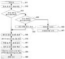
종래의 혈액 검사 장치는, 일반적으로 피부를 천자(穿刺)하는 수단으로서 바늘을 이용하였다(예를 들면, 특허 문헌 1 참조). 종래의 바늘을 천자 수단으로 하는 혈액 검사 장치(1)는, 도 1에 도시하는 바와 같이, 케이스를 형성하는 하우징(2)과, 하우징(2)의 일단이 개구된 통체(3)와, 통체(3) 내를 왕복하는 플런저(4)와, 플런저(4)에 일단이 연결된 핸들(5)과, 핸들(5)이 하우징(2)에 걸리는 계지부(6)와, 핸들(5)을 통체(3)의 개구부(3a) 측에 바이어스하는 스프링(7)과, 플런저(4)에 일단이 파지되면서 타단에는 채혈침(이하, 단순히 바늘이라고 한다)(8)이 장착되는 란셋(lancet)(9)과, 개구부(3a) 측에 혈액 센서(10)를 보관하는 보관부(11)와, 센서(10)의 출력이 접속된 전기 회로부(12)를 포함한다.The conventional blood test apparatus generally used a needle as a means of puncturing the skin (see
종래의 혈액 검사 장치(1)를 이용하여 혈액 검사를 하려면, 이하에 기술하는 준비 작업이 필요하다. 이미 검사한 혈액의 영향을 배제하기 위해, 혈액 센서(10)와 바늘(8)을 교환한다. 사용이 끝난 혈액 센서(10)를 제거하고 새로운 혈액 센서(10)를 장착하려면, 보관부(11)를 제외하고 사용이 끝난 센서(10)를 떼어낸다. 다음으로, 새로운 혈액 센서(10)를 보관부(11)에 장착한다. 그리고 다시 개구부(3a)에 장착한다. 이때 보관부(11)의 근방이 혈액 등으로 더러워져 있으면 청소한다.In order to perform a blood test using the conventional
이들 준비 작업은, 눈이 나쁜 당뇨병 환자에게 있어서는 번잡한 작업이다. 게다가, 이러한 작업을 하루 수차례 행하지 않으면 안 되어, 그 부담이 컸다.These preparations are cumbersome for diabetics with bad eyes. In addition, this work had to be performed several times a day, and the burden was large.
이와 같은 준비 작업의 뒤, 혈액 검사 장치(1)를 환자의 피부에 맞대어, 계지부(6)의 걸림을 해제한다. 그러면, 스프링(7)에 의해 바이어스된 핸들(5)이 화살표(14) 방향으로 발사된다. 핸들(5)의 걸림 해제에 의해, 이 핸들(5)에 플런저(4)와 란셋(9)을 통해 연결된 바늘(8)도 동시에 발사된다. 바늘(8)은, 센서(10)를 찢고 피부(13)를 천자한다.After such preparatory work, the
천자된 피부(13)로부터 소량의 혈액이 유출된다. 유출된 혈액은 혈액 센서(10)의 내부로 들어간다. 센서(10)로 들어간 혈액은 센서(10)의 내부에서 환자의 혈당치에 부합한 화학 변화를 일으킨다. 화학 변화에 의해 생긴 전류는 전기 회로부(12)로 유도되어 혈당치가 계산된다. 계산된 혈당치는 표시부(15)에 표시된다. 구해진 혈당치에 기초하여, 예를 들면, 환자에게 투여하는 인슐린량의 기초 데이터가 제공된다.A small amount of blood flows out of the
한편, 천자 수단으로서 레이저를 이용한 혈액 샘플을 채취하는 장치도 제안되어 있다(특허 문헌 2 및 3 참조). 레이저를 이용하면, 바늘의 교환이 불필요하게 되는 등의 이점이 있고, 또한 천자 시의 환자의 통증도 경감시킬 수 있다. 특히, 특허 문헌 2에는, 레이저를 천자 수단으로서 이용하여 혈액 샘플을 채취하는 장치로서, 천자하고자 하는 피부 영역을 흡인함으로써 그곳에서의 혈행을 활발하게 한 것이 기재되어 있다.On the other hand, the apparatus which collects the blood sample using a laser as a puncturing means is also proposed (refer
특허 문헌 1: 일본 특허공표 2003-524496호 공보Patent Document 1: Japanese Patent Publication No. 2003-524496
특허 문헌 2: 일본 특허공표 2004-533866호 공보Patent Document 2: Japanese Patent Publication No. 2004-533866
특허 문헌 3: 일본 특허공개 2004-195245호 공보Patent Document 3: Japanese Patent Application Laid-Open No. 2004-195245
〈발명이 해결하려고 하는 과제〉<Problem that invention is going to solve>
그러나, 천자하고자 하는 피부 영역을 단순히 흡인하는 것만으로는, 천자 영역에 있어서 혈액 흐름을 자극하는 효과가 한정되게 되어, 원하는 혈액량을 얻을 수 없을 우려가 있다.However, by simply sucking on the skin region to be punctured, the effect of stimulating blood flow in the puncture region is limited, and there is a fear that a desired blood volume cannot be obtained.
또한, 흡인에 관해서는, 실제의 적용 장면을 상정한 경우, 다음과 같은 문제점도 염려된다. 예를 들면, 펌프 등의 부압 수단에 의해 흡인을 행하는 것을 생각한 경우, 혈액의 채취를 검지하여 부압 수단의 동작을 정지시키면, 환자는 부압 수단의 동작음의 정지를 계기로 혈액 검사 장치나 손가락을 움직여 버려, 혈액 채취 후의 측정을 안정적으로 행할 수 없을 우려가 있다. 또한, 부압 수단을 동작시켜 혈액을 채취하는 경우는, 환자에 따라 피부의 경도(硬度) 등의 상황이 상이하므로, 부압 수단의 효과(일정한 흡인력)에 따라서는 혈액의 채취량에 과부족이 생길 우려가 있다. 흡인력을 크게 너무 크게 하면, 혈액을 과잉 채취하여 환자에게 부담을 주는 결과가 되고, 흡인력을 작게 너무 작게 하면, 측정에 필요 충분한 소량의 혈액 채취도 어려워진다.In addition, with regard to suction, the following problems are also concerned when the actual application scene is assumed. For example, when it is considered that suction is performed by a negative pressure means such as a pump, when blood collection is detected and the operation of the negative pressure means is stopped, the patient stops the operation of the negative pressure means and stops the blood test apparatus or the finger. It may move and may not be able to perform the measurement after blood collection stably. In the case where blood is collected by operating the negative pressure means, the hardness and the like of the skin vary depending on the patient. Therefore, there is a fear that excessive or insufficient blood collection may occur depending on the effect (constant suction force) of the negative pressure means. have. If the suction force is made too large, an excessive amount of blood will be collected to burden the patient. If the suction force is made too small, it will be difficult to collect a small amount of blood necessary for measurement.
요컨대, 실제의 적용 장면을 상정한 경우에는, 단순한 흡인의 온·오프만으로는, 환자에게 부담을 주지 않고 측정에 필요 충분한 소량의 혈액을 채취하여 안정된 측정을 행할 수 없을 우려가 있다. 이것을 달성하기 위해서는, 보다 세세한 제어가 필요하지만, 종래는 이와 같은 관점에서의 연구·개발은 이루어지지 않았다.In short, in the case of assuming the actual application scene, there is a possibility that by simply turning on and off the suction, a small amount of blood sufficient for measurement can be collected and a stable measurement cannot be performed without burdening the patient. In order to achieve this, finer control is required, but in the related art, research and development have not been made in view of such a situation.
본 발명은, 간단한 구성으로, 환자에게 부담을 주지 않고 소량으로 측정에 필요 충분한 혈액을 확실히 채취하여, 안정적으로 측정할 수 있는 혈액 검사 장치 및 그 제어 방법을 제공하는 것을 목적으로 한다.SUMMARY OF THE INVENTION An object of the present invention is to provide a blood test apparatus and a control method capable of reliably collecting and stably measuring blood sufficient for measurement in a small amount without burdening a patient with a simple configuration.
〈과제를 해결하기 위한 수단〉〈Means for solving the problem〉
본 발명의 혈액 검사 장치는, 레이저를 이용해 피부를 천자하여 혈액을 채취해 측정하는 혈액 검사 장치로서, 레이저광을 조사하여 피부를 천자하는 레이저 천자 수단과, 천자된 피부로부터 유출되는 혈액을 채취해 분석하는 혈액 센서와, 상기 혈액 센서를 지지하는 홀더와, 상기 혈액 센서의 근방 공간에 부압을 공급하는 부압 수단과, 상기 부압 수단의 동작을 제어하는 부압 제어 수단을 갖고, 상기 부압 제어 수단은, 피부가 상기 홀더에 맞닿고 나서 상기 측정이 완료될 때까지의 기간 중 적어도 일부의 기간에 있어서, 상기 혈액 센서의 근방 공간의 부압의 크기를 소정의 패턴으로 변화시키는 구성을 채용한다.The blood test apparatus of the present invention is a blood test apparatus for puncturing skin using a laser to collect and measure blood, comprising: laser puncturing means for puncturing the skin by irradiating laser light, and blood flowing out of the punctured skin The negative pressure control means has a blood sensor to be analyzed, a holder for supporting the blood sensor, negative pressure means for supplying negative pressure to a space near the blood sensor, and negative pressure control means for controlling the operation of the negative pressure means. In the period of at least a part of the period from the skin contacting the holder to the completion of the measurement, a configuration is adopted in which the magnitude of the negative pressure in the space near the blood sensor is changed in a predetermined pattern.
본 발명의 혈액 검사 장치는, 레이저를 이용해 피부를 천자하여 혈액을 채취해 측정하는 혈액 검사 장치로서, 레이저광을 조사하여 피부를 천자하는 레이저 천자 수단과, 천자된 피부로부터 유출되는 혈액을 채취해 분석하는 혈액 센서와, 상기 혈액 센서를 지지하는 홀더와, 상기 혈액 센서의 근방 공간에 부압을 공급하는 부압 수단을 갖고, 상기 부압 수단은, 수동 펌프를 구동하여 부압을 발생시키는 구성을 채용한다.The blood test apparatus of the present invention is a blood test apparatus for puncturing skin using a laser to collect and measure blood, comprising: laser puncturing means for puncturing the skin by irradiating laser light, and blood flowing out of the punctured skin It has a blood sensor to analyze, the holder which supports the said blood sensor, and the negative pressure means which supplies a negative pressure to the space near the said blood sensor, The negative pressure means adopts the structure which drives a manual pump and produces negative pressure.
본 발명의 혈액 검사 장치의 제어 방법은, 레이저광을 조사해 피부를 천자 하는 레이저 천자 수단과, 천자된 피부로부터 유출되는 혈액을 채취해 분석하는 혈액 센서와, 상기 혈액 센서를 지지하는 홀더와, 상기 혈액 센서의 근방 공간에 부압을 공급하는 부압 수단과, 상기 부압 수단의 동작을 제어하는 부압 제어 수단을 갖는 혈액 검사 장치의 제어 방법으로서, 피부가 상기 홀더에 맞닿고 나서 상기 측정이 완료될 때까지의 기간 중 적어도 일부의 기간에 있어서, 상기 혈액 센서의 근방 공간의 부압의 크기를 소정의 패턴으로 변화시키도록 하였다.The control method of the blood test apparatus of the present invention includes a laser puncturing means for irradiating laser light to puncture the skin, a blood sensor for collecting and analyzing blood flowing out of the punctured skin, a holder for supporting the blood sensor, and A control method of a blood test apparatus having a negative pressure means for supplying a negative pressure to a space near a blood sensor and a negative pressure control means for controlling the operation of the negative pressure means, wherein the skin is in contact with the holder until the measurement is completed. In at least part of the period of time, the magnitude of the negative pressure in the space near the blood sensor was changed in a predetermined pattern.
〈발명의 효과〉<Effects of the Invention>
본 발명에 따르면, 간단한 구성으로, 환자에게 부담을 주지 않고 소량으로 측정에 필요 충분한 혈액을 확실히 채취하여, 안정적으로 측정할 수 있다.According to the present invention, it is possible to reliably collect a sufficient amount of blood necessary for measurement in a small amount and stably measure, without burdening the patient with a simple configuration.
도 1은 종래의 혈액 검사 장치의 일례를 도시하는 단면도이다.1 is a cross-sectional view showing an example of a conventional blood test apparatus.
도 2는 본 발명의 혈액 검사 장치의 제1 예를 도시하는 분해 조립 사시도이다.2 is an exploded perspective view showing a first example of the blood test apparatus of the present invention.
도 3은 본 발명의 혈액 검사 장치의 제2 예를 도시하는 분해 조립 사시도이다.3 is an exploded perspective view showing a second example of the blood test apparatus of the present invention.
도 4는 도 3의 혈액 검사 장치의 측면도이다.4 is a side view of the blood test apparatus of FIG. 3.
도 5는 본 발명의 혈액 검사 장치에서의 레이저 발사 장치의 일례를 도시하는 외관 사시도이다.5 is an external perspective view showing an example of a laser firing apparatus in the blood test apparatus of the present invention.
도 6a는 도 5의 레이저 발사 장치의 일 구성예를 도시하는 단면도이다.FIG. 6A is a cross-sectional view showing an example of the configuration of the laser firing apparatus of FIG. 5.
도 6b는 도 5의 레이저 발사 장치의 다른 구성예를 도시하는 단면도이다.6B is a cross-sectional view showing another example of the configuration of the laser firing apparatus of FIG. 5.
도 7은 본 발명의 혈액 검사 장치에서의 레이저 발사 장치의 다른 예를 도시하는 부분 절개 사시도이다.Fig. 7 is a partially cutaway perspective view showing another example of the laser firing apparatus in the blood test apparatus of the present invention.
도 8은 본 발명의 혈액 검사 장치에서의 혈액 센서의 일례를 도시하는 단면도이다.It is sectional drawing which shows an example of the blood sensor in the blood test apparatus of this invention.
도 9는 본 발명의 혈액 검사 장치에서의 혈액 센서의 다른 예를 도시하는 단면도이다.It is sectional drawing which shows the other example of the blood sensor in the blood test apparatus of this invention.
도 10은 도 9의 혈액 센서의 천자 시의 단면도이다.10 is a cross-sectional view when puncturing the blood sensor of FIG. 9.
도 11은 본 발명의 혈액 검사 장치에서의 혈액 센서의 또 다른 예를 도시하는 단면도이다.It is sectional drawing which shows the other example of the blood sensor in the blood test apparatus of this invention.
도 12는 도 8의 혈액 센서의 투시 평면도이다.12 is a perspective plan view of the blood sensor of FIG. 8.
도 13은 본 발명의 혈액 검사 장치에서의 혈액 센서의 또 다른 예를 도시하는 투시 평면도이다.It is a perspective top view which shows the other example of the blood sensor in the blood test apparatus of this invention.
도 14는 본 발명의 혈액 검사 장치에서의 혈액 센서의 또 다른 예를 도시하는 투시 평면도이다.It is a perspective top view which shows the other example of the blood sensor in the blood test apparatus of this invention.
도 15는 도 8의 혈액 센서의 분해 평면도로서, (a)는 커버의 평면도, (b)는 스페이서의 평면도, (c)는 기판의 평면도이다.FIG. 15 is an exploded plan view of the blood sensor of FIG. 8, (a) is a plan view of the cover, (b) is a plan view of the spacer, and (c) is a plan view of the substrate.
도 16은 본 발명의 혈액 검사 장치에서의 혈액 센서 유닛과 그 근방을 도시하는 단면도이다.It is sectional drawing which shows the blood sensor unit and its vicinity in the blood test apparatus of this invention.
도 17은 본 발명의 혈액 검사 장치에서의 혈액 센서 유닛을 당해 혈액 검사 장치에 장착하기 위한 가이드부의 일례를 도시하는 주요부 전개 정면도이다.It is a principal part development front view which shows an example of the guide part for attaching the blood sensor unit in the blood test apparatus of this invention to the said blood test apparatus.
도 18은 본 발명의 혈액 검사 장치에서의 혈액 센서 유닛의 일례를 도시하는 사시도이다.It is a perspective view which shows an example of the blood sensor unit in the blood test apparatus of this invention.
도 19는 도 18의 혈액 센서 유닛에서의 홀더의 하단 근방의 일 구성예를 도시하는 주요부 단면도이다.19 is an essential part cross sectional view showing a configuration example near the lower end of the holder in the blood sensor unit of FIG. 18.
도 20은 본 발명의 혈액 검사 장치에서의 혈액 센서 유닛의 하단 근방의 다른 구성예를 도시하는 주요부 단면도이다.20 is a cross sectional view of an essential part showing another configuration example in the vicinity of a lower end of the blood sensor unit in the blood test apparatus of the present invention.
도 21은 본 발명의 혈액 검사 장치에서의 혈액 센서 유닛의 하단 근방의 또 다른 예를 도시하는 주요부 단면도이다.Fig. 21 is a sectional view of principal parts showing still another example of the vicinity of the lower end of the blood sensor unit in the blood test apparatus of the present invention.
도 22는 도 18의 혈액 센서 유닛의 단면도이다.22 is a cross-sectional view of the blood sensor unit of FIG. 18.
도 23은 본 발명의 혈액 검사 장치에서의 혈액 센서 유닛의 다른 예를 도시 하는 단면도이다.It is sectional drawing which shows the other example of the blood sensor unit in the blood test apparatus of this invention.
도 24는 본 발명의 혈액 검사 장치에서의 혈액 센서 유닛의 또 다른 예를 도시하는 단면도이다.It is sectional drawing which shows the other example of the blood sensor unit in the blood test apparatus of this invention.
도 25는 도 24의 혈액 센서 유닛의 평면도이다.25 is a plan view of the blood sensor unit of FIG. 24.
도 26은 본 발명의 혈액 검사 장치에서의 레이저 초점에서 천자 대상까지의 거리(X축)와 번 패턴(burn pattern) 직경(Y축)의 관계를 나타내는 그래프이다.It is a graph which shows the relationship of the distance (X-axis) and burn pattern diameter (Y-axis) from a laser focus to a puncture object in the blood test apparatus of this invention.
도 27은 본 발명의 혈액 검사 장치에서의 부압실 및 부압 경로의 일례를 도시하는 주요부 확대 단면도이다.It is an enlarged sectional view of the principal part which shows an example of the negative pressure chamber and the negative pressure path | route in the blood test apparatus of this invention.
도 28은 본 발명의 혈액 검사 장치에서의 부압실 및 부압 경로의 다른 예를 도시하는 주요부 확대 단면도이다.It is a principal part enlarged sectional view which shows the other example of the negative pressure chamber and the negative pressure path | pass in the blood test apparatus of this invention.
도 29는 도 27에 도시하는 부압실 용적의 설명도이다.It is explanatory drawing of the negative pressure chamber volume shown in FIG.
도 30은 도 28에 도시하는 부압실 용적의 설명도이다.It is explanatory drawing of the negative pressure chamber volume shown in FIG.
도 31은 본 발명의 혈액 검사 장치에서의 전기 회로부의 블록도이다.Fig. 31 is a block diagram of an electric circuit part in the blood test apparatus of the present invention.
도 32는 본 발명의 혈액 검사 장치를 이용한 검사 순서의 일례를 나타내는 플로우차트이다.It is a flowchart which shows an example of the test procedure using the blood test apparatus of this invention.
도 33a는 본 발명의 혈액 검사 장치를 이용한 검사 순서의 일례를 보다 구체적으로 도시하는 공정별 단면도이다.33A is a cross-sectional view for each step showing an example of a test procedure using the blood test apparatus of the present invention in more detail.
도 33b는 도 33a에 계속되는 공정별 단면도이다.33B is a cross-sectional view of the process following FIG. 33A.
도 33c는 도 33b에 계속되는 공정별 단면도이다.33C is a cross-sectional view of the process following FIG. 33B.
도 33d는 도 33c에 계속되는 공정별 단면도이다.33D is a cross-sectional view of the process following FIG. 33C.
도 34는 본 발명의 혈액 검사 장치를 이용한 검사 순서의 다른 예를 나타내는 플로우차트이다.It is a flowchart which shows the other example of the test procedure using the blood test apparatus of this invention.
도 35는 본 발명의 혈액 검사 장치에서의 부압 제어의 일례를 설명하기 위한 도면이다.It is a figure for demonstrating an example of negative pressure control in the blood test apparatus of this invention.
도 36은 도 35에서 설명되는 부압 제어에 의해 피부가 솟아오르는 모습을 모식적으로 도시하는 도면이다.FIG. 36 is a diagram schematically showing how the skin rises by the negative pressure control described in FIG. 35.
도 37은 본 발명의 혈액 검사 장치에서의 부압 제어의 다른 예를 설명하기 위한 도면이다.It is a figure for demonstrating the other example of the negative pressure control in the blood test apparatus of this invention.
도 38은 본 발명의 혈액 검사 장치에 포함되는 레이저 천공 장치의 일례를 도시하는 분해 조립 사시도이다.38 is an exploded perspective view illustrating an example of a laser drilling device included in the blood test apparatus of the present invention.
도 39는 본 발명의 혈액 검사 장치에서의 레이저 분기 제어의 일례를 도시하는 도면이다.It is a figure which shows an example of the laser branch control in the blood test apparatus of this invention.
도 40은 도 39의 레이저 분기 제어를 설명하기 위한 도면이다.40 is a diagram for explaining the laser branch control of FIG. 39.
도 41은 도 39의 레이저 분할 제어에 사용 가능한 큐브 형상 광학 소자의 사시도이다.FIG. 41 is a perspective view of a cube-shaped optical element that can be used for laser segmentation control in FIG. 39.
도 42는 도 39의 레이저 분할 제어에 사용 가능한 큐브의 일례를 도시하는 도면으로서, (a)는 레이저광의 분기를 삼차원의 이미지로 도시하는 도면이고, (b)는 그 분기를 실현하는 큐브의 일례를 도시하는 사시도이다.FIG. 42 is a diagram showing an example of a cube usable for the laser segmentation control in FIG. 39, (a) is a diagram showing a three-dimensional image of a branch of laser light, and (b) is an example of a cube for realizing the branch. It is a perspective view which shows.
도 43은 본 발명의 혈액 검사 장치에 있어서 레이저광을 경사 방향으로부터 조사하여 천자하는 모습을 도시하는 도면이다.Fig. 43 is a diagram showing how the laser beam is irradiated from the oblique direction and punctured in the blood test apparatus of the present invention.
도 44는 레이저광 조사형의 변화를 나타내는 도면이다.It is a figure which shows the change of a laser beam irradiation type.
도 45는 본 발명의 혈액 검사 장치에서의 레이저 출력 제어의 다른 예를 도시하는 개략도이다.45 is a schematic view showing another example of laser power control in the blood test apparatus of the present invention.
도 46은 본 발명의 혈액 검사 장치에서의 레이저 펄스 제어의 일례를 도시하는 도면이다.It is a figure which shows an example of the laser pulse control in the blood test apparatus of this invention.
도 47은 도 46의 레이저 펄스 제어에 의한 천자 상태를 도시하는 단면도이다.FIG. 47 is a cross-sectional view showing a puncture state by the laser pulse control of FIG. 46.
도 48은 본 발명의 혈액 검사 장치에서의 레이저 출력 제어의 또 다른 예를 나타내는 도면으로, (a)는 회로도, (b)는 플래시램프로의 입력 전류의 시간 변화를 나타내는 도면, (c)는 레이저 출력의 시간 변화를 나타내는 도면이다.FIG. 48 is a diagram showing another example of laser power control in the blood test apparatus of the present invention, (a) is a circuit diagram, (b) is a diagram showing a time change of an input current to a flash lamp, (c) is It is a figure which shows the time change of a laser output.
도 49는 본 발명의 혈액 검사 장치에서의 레이저 출력 제어의 또 다른 예를 나타내는 도면으로, (a)는 회로도, (b)는 플래시램프로의 입력 전류의 시간 변화를 나타내는 도면, (c)는 레이저 출력의 시간 변화를 나타내는 도면이다.Fig. 49 is a diagram showing another example of laser power control in the blood test apparatus of the present invention, (a) is a circuit diagram, (b) is a diagram showing a time change of an input current to a flash lamp, (c) is It is a figure which shows the time change of a laser output.
도 50은 본 발명의 혈액 검사 장치의 전원 제어부의 제1 예를 도시하는 블록도이다.It is a block diagram which shows the 1st example of the power supply control part of the blood test apparatus of this invention.
도 51은 도 50의 전원 제어부의 제어 순서의 제1 예를 나타내는 플로우차트이다.FIG. 51 is a flowchart illustrating a first example of a control procedure of the power control unit of FIG. 50.
도 52는 도 50의 전원 제어부의 제어 순서의 제2 예를 나타내는 플로우차트이다.FIG. 52 is a flowchart illustrating a second example of a control procedure of the power control unit of FIG. 50.
도 53은 도 50의 전원 제어부의 제어 순서의 제3 예를 나타내는 플로우차트 이다.53 is a flowchart illustrating a third example of the control procedure of the power control unit of FIG. 50.
도 54는 도 50의 전원 제어부의 제어 순서의 제4 예를 나타내는 플로우차트이다.54 is a flowchart illustrating a fourth example of the control procedure of the power control unit of FIG. 50.
도 55는 본 발명의 혈액 검사 장치의 전원 제어부의 제2 예를 도시하는 블록도이다.It is a block diagram which shows the 2nd example of the power supply control part of the blood test apparatus of this invention.
도 56은 도 55의 전원 제어부의 제어 순서의 제1 예를 나타내는 플로우차트이다.56 is a flowchart illustrating a first example of a control procedure of the power control unit of FIG. 55.
도 57은 도 55의 전원 제어부의 제어 순서의 제2 예를 나타내는 플로우차트이다.FIG. 57 is a flowchart illustrating a second example of a control procedure of the power control unit of FIG. 55.
도 58은 본 발명의 혈액 검사 장치의 전원 제어부의 제3 예를 도시하는 블록도이다.It is a block diagram which shows the 3rd example of the power supply control part of the blood test apparatus of this invention.
도 59는 도 58의 전원 제어부의 제어 순서의 제1 예를 나타내는 플로우차트이다.FIG. 59 is a flowchart illustrating a first example of a control procedure of the power control unit of FIG. 58.
도 60은 도 58의 전원 제어부의 제어 순서의 제2 예를 나타내는 플로우차트이다.60 is a flowchart illustrating a second example of a control procedure of the power control unit of FIG. 58.
도 61a는 전지의 잔량에 기초하여, 레이저 발사 장치의 충전을 위한 충전량을 단계적으로 설정하는 방법을 설명하는 그래프이다.FIG. 61A is a graph for explaining a method for setting a charging amount for charging a laser firing apparatus in stages based on the remaining amount of battery. FIG.
도 61b는 전지의 잔량에 기초하여, 레이저 발사 장치의 충전을 위한 충전량을 연속적으로 설정하는 방법을 설명하는 그래프이다.FIG. 61B is a graph for explaining a method for continuously setting the charge amount for charging the laser firing apparatus based on the remaining amount of the battery. FIG.
도 61c는 전지의 잔량에 기초하여, 레이저 발사 장치의 충전을 위한 충전량 을 가변 곡선에 맞추어 설정하는 방법을 설명하는 그래프이다.Fig. 61C is a graph for explaining a method for setting the charging amount for charging the laser firing apparatus according to the variable curve based on the remaining amount of the battery.
도 62는 충전량을 변화시켰을 때의, 전지의 전압(Y축)과 전지 잔량(X축)의 관계를 나타내는 그래프이다.Fig. 62 is a graph showing the relationship between the voltage (Y axis) of the battery and the remaining battery amount (X axis) when the charge amount is changed.
도 63은 본 발명의 레이저 천공 장치를 포함하는 혈액 검사 장치에서의 레이저 분기 제어의 다른 예를 도시하는 도면으로, (a)는 2분기의 경우를 도시하는 도면, (b)는 4분기의 경우를 도시하는 도면이다.Fig. 63 is a diagram showing another example of laser branch control in the blood test apparatus including the laser drilling device of the present invention, (a) is a diagram showing a case of two quarters, and (b) is of a fourth quarter. It is a figure which shows.
도 64는 도 63의 레이저 분기 제어에 이용되는 광섬유 방향성 결합기의 구성을 도시하는 개략도이다.64 is a schematic diagram showing a configuration of an optical fiber directional coupler used for laser branch control in FIG.
도 65는 본 발명의 레이저 천공 장치를 포함하는 혈액 검사 장치에서의 레이저 분기 제어의 또 다른 예를 도시하는 도면이다.Fig. 65 is a diagram showing another example of laser branch control in the blood test apparatus including the laser drilling device of the present invention.
이하, 도면에 기초하여, 본 발명의 혈액 검사 장치를 설명한다. 한편, 각 도면에 있어서, 공통되는 부재에는 동일한 부호를 부여하고, 적절하게 그 설명을 생략한다.EMBODIMENT OF THE INVENTION Hereinafter, the blood test apparatus of this invention is demonstrated based on drawing. In addition, in each figure, the same code | symbol is attached | subjected to the common member, and the description is abbreviate | omitted suitably.
장치 전체도 1Device Overall Diagram 1
도 2는 본 발명의 혈액 검사 장치의 전체 구성의 제1 예를 도시하는 분해 조립 사시도이다.2 is an exploded perspective view illustrating a first example of the entire configuration of the blood test apparatus of the present invention.
도 2에 도시하는 혈액 검사 장치(31)의 하부 케이스(32)의 내부에는, 레이저 발사 장치(33)와, 흡인 펌프(부압 펌프)(34a), 펌프 밸브 유닛(34b), 및 대기 개방 스위치(34c)로 구성된 부압(負壓) 수단(34)과, 전기 부품에 전력을 공급하는 전 지(35)와, 이들 부품 위에 장착된 전기 회로부(36)와, 전기 회로부(36) 위에 장착됨과 함께, 예를 들면 액정으로 구성된 표시부(37) 등의 부재가 내장된다.Inside the
각 부재가 내장된 하부 케이스(32)에 상부 케이스(38)가 덮혀져 장치 본체(39)가 구성된다. 상부 케이스(38)에는, 투명 표시창(38a)이 표시부(37)에 대응한 위치에 마련된다.The
장치 본체(39)는 혈액 센서 유닛(44)과 어댑터(40)를 통해 접속된다. 어댑터(40)의 한쪽은 원통상의 통체이며, 혈액 센서 유닛(44)이 탈착 가능하게 장착된다. 혈액 센서 유닛(44)은 홀더(41)와, 홀더(41)의 내부에 장착된 혈액 센서(42)로 구성된다. 혈액 센서 유닛(44)의 중앙에 마련된 창(43)은 레이저 발사 장치(33)의 레이저 발사구로부터의 레이저광을 통과시키는 부분이다. 창(43)은 관통공이라도 되고, 레이저광을 투과하는 재료로 형성된 부재라도 무방하다.The
장치 전체도 2Device Overall Diagram 2
도 3은 본 발명의 혈액 검사 장치의 전체 구성의 제2 예를 도시하는 분해 조립 사시도이다. 도 4는 그 측면도이다. 도 3 및 도 4에 도시하는 혈액 검사 장치(31a)는, 부압 수단(140)을 구성하는 부압 펌프로서 수동 흡인할 수 있는 수동 펌프를 갖는 점에서, 도 2에 도시하는 혈액 검사 장치(31)와 다르다. 이하, 이 차이점에 대해 설명한다.3 is an exploded perspective view showing a second example of the overall configuration of the blood test apparatus of the present invention. 4 is a side view thereof. The
혈액 검사 장치(31a)는 수동 펌프(부압 펌프)(141)와, 수동 펌프(141)를 수동으로 구동하는 수동 펌프 노브(142)를 포함하는 부압 수단(140)을 갖는다. 대기 개방 스위치(144)는 펌프 밸브 유닛(143)에서 발생하는 부압을 대기로 개방한다.The
수동 펌프 노브(142)는 활 형상을 하고 있으며, 일단은 받침축(142a)이 되고, 타단은 작용부(142b)가 된다(도 4 참조). 수동 펌프 노브(142)는 받침축(142a)을 중심으로 회동할 수 있다. 작용부(142b)가 수동 펌프(141)에 동력을 전달한다. 환자는 수동 펌프 노브(142)를 장치 본체(39)와 함께 쥐고 작용부(142b)를 상하 이동시킬 수 있다. 이 상하 이동에 의해 수동 펌프(141)가 동작해 부압이 발생한다.The
작용부(142b)의 상하 이동에 의해 피부가 솟아오르는 것을 확인하면서 적정한 부압을 인가하도록 하기 위해 부압실(60)(도 16 등 참조)의 내부를 볼 수 있도록 혈액 센서 유닛(44)의 외장을 투명 부재로 형성하는 것이 바람직하다. 혈액 센서 유닛(44)의 외장을 모두 투명 부재로 형성해도 되고, 혈액 센서 유닛(44)의 선단(41h)측(부압실(60)측)만을 투명 부재로 형성해도 된다. 수동 펌프 노브(142)의 피파지부(142c)에는 손가락 형태의 요철을 마련하여 미끄러짐을 방지해도 된다.In order to apply the appropriate negative pressure while confirming that the skin rises due to the vertical movement of the
부압 수단(140)을 수동 구동으로 함으로써 부압 수단(140)을 구동하는 전원이 불필요해 진다. 따라서, 전지(35)를 장수명화할 수 있어 휴대용 혈액 검사 장치에 적합하다.By manually driving the negative pressure means 140, the power source for driving the negative pressure means 140 becomes unnecessary. Therefore, the
레이저 발사 장치(렌즈 포함)의 제1 형태에 대해About the first form of the laser firing apparatus (including a lens)
본 발명의 혈액 검사 장치(31, 31a)는 피부를 천자(穿刺)하는 수단으로서 레이저를 이용한다. 레이저광을 피부에 조사하면, 피부의 수분의 OH기에 레이저광이 흡수되어 순간적으로 열이 상승하여 기화한다. 이때에 주위의 세포도 함께 기화하여 피부에 구멍이 뚫린다.The
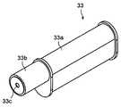
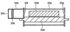
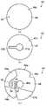
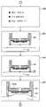
혈액 검사 장치(31, 31a)에는 레이저 발사 장치가 수납된다. 도 5는 혈액 검 사 장치(31, 31a)에 수납되는 레이저 발사 장치(33)의 외관 사시도이다. 또한, 도 6a 및 도 6b는 각각 레이저 발사 장치(33)의 단면도이다. 도 6a에서는 레이저 결정(33d)이 부분 투과경(33f)과 전반사경(33g)이 설치된 벽에 둘러싸인 내부에 배치되지만, 도 6b에서는 레이저 결정(33d)이 양 측면에 부분 투과경(33f)과 전반사경(33g)을 구비하고, 레이저 결정(33d)은 통체(33b)의 외벽과 내부벽(칸막이)에 장착된다. 즉, 도 6b에서는 레이저 결정(레이저 로드)(33d)이 길어져 내부벽(칸막이)보다 앞으로 신장되어 있다.The laser test apparatus is accommodated in the
레이저 발사 장치(33)는 발진 튜브(33a)와, 발진 튜브(33a)의 전방에 연결된 원통상의 통체(33b)로 구성된다. 통체(33b)의 전방 중앙에는 레이저 발사구(33c)가 마련된다.The
발진 튜브(33a)의 내부에는 에르븀을 도핑한 Er:YAG(이트륨·알루미늄·가넷) 또는 홀륨을 도핑한 Ho:YAG 레이저 결정(33d)과, 크세논 플래시램프를 이용한 여기 광원(33e)이 내장된다. 발진 튜브(33a)의 일단에는 부분 투과경(33f)이 장착된다(특히 도 6a). 부분 투과경(33f)의 투과율은 약 1% 내지 10%로 하면 된다. 발진 튜브(33a)의 타단에는 99% 내지 100%의 전반사경(33g)이 장착된다(도 6a, 도 6b). 또한, 부분 투과경(33f)이나 전반사경(33g)을 이용하지 않고, 레이저 결정(33d)의 단면에 스퍼터링 등으로 동일한 특성을 갖는 막을 형성한 것이라도 무방하다.Inside the
통체(33b)의 내부에는 볼록 렌즈(초점 렌즈)(33h)가 장착된다. 볼록 렌즈(33h)는 레이저를 혈액 센서(42)의 면의 근방에 집광시킨다(상세는 후술함). 전 반사경(33g)과 YAG 레이저 결정(33d)과 부분 투과경(33f)과 렌즈(33h)와 레이저 발사구(33c)는 이 순서로 배치된다.A convex lens (focal lens) 33h is mounted inside the
레이저 발사 장치(33)로부터 레이저광이 발사되는 프로세스를 설명한다. 여기 광원(33e)으로부터 발사된 여기광은 예를 들면 Er:YAG 레이저 결정(33d)의 내부로 들어가 Er(에르븀) 이온을 여기하여 에너지가 높은 상태를 만들어 반전 분포 상태가 되어, 전반사경(33g)과 YAG 레이저 결정(33d)과 부분 투과경(33f)의 사이를 반사하여 공진함과 함께 증폭된다. Ho(홀륨)의 경우도 마찬가지이다. 증폭된 레이저광의 일부는 유도 방출에 의해 부분 투과경(33f)을 통과한다. 부분 투과경(33f)을 통과한 레이저광은 렌즈(33h)를 통과하여 레이저 발사구(33c)로부터 방사된다. 후술하는 바와 같이, 레이저 발사구(33c)로부터 방사된 레이저광이 피부를 천자(조사)한다.The process by which laser light is emitted from the
레이저 발사 장치의 제2 형태에 대해About the second form of the laser firing apparatus
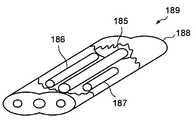
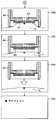
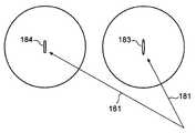
도 7에 레이저 발사 장치의 다른 예를 도시한다. 도 7에 도시하는 레이저 발사 장치(189)는 1개의 플래시램프(185)를 여기 광원으로 하여, 여기광을 2종의 레이저 결정에 조사한다. 이때, 각각의 결정으로부터 레이저광이 출력된다. 2종의 결정을 이용함으로써 레이저광의 강도나 파장이 상이한 레이저광을 출력할 수 있다.7 shows another example of the laser firing apparatus. The
레이저 발사 장치(189)는, 도 7에 도시하는 바와 같이, 단면이 타원형인 통체를 2개 겹친 형상의 케이스(188)와, 케이스(188)의 중앙부에 배치된 레이저를 여기하기 위한 플래시램프(185)와, 플래시램프(185)의 양측에 배치된 레이저 발진을 위한 제1 결정(186) 및 제2 결정(187)을 포함한다. 타원 형상의 케이스(188)에는 3 개의 초점이 존재한다. 케이스(188)는 2개의 타원이 겹친 형상인데, 각각의 타원에 2개의 초점을 갖고 그 중 1개의 초점을 공통된 초점이 되도록 배치하고 있기 때문에 3개의 초점이 존재한다. 3개의 초점 중 한쪽의 초점에 제1 결정(186)을 배치하고, 다른 쪽의 초점에 제2 결정(187)을 배치한다. 그리고, 2개의 초점을 공유하는 중앙부에 플래시램프(185)를 배치한다. 1개의 플래시램프(185)로 2개의 결정(186, 187)의 각각으로부터 레이저광을 얻을 수 있으므로 레이저 발사 장치의 소형화와 저가격화가 도모된다.As shown in FIG. 7, the
레이저의 출력 강도는 플래시램프(185)의 발광 강도에도 비례하지만, 결정(186) 및 결정(187)의 체적에도 비례한다. 따라서, 같은 지름이라도 길이가 상이한 2개의 결정을 배치하면, 1개의 플래시램프(185)로 강도가 상이한 2개의 레이저광을 얻을 수 있다.The output intensity of the laser is proportional to the light emission intensity of the
또한, 동일한 체적의 결정을 이용하면, 동일한 강도의 2개의 레이저광을 동시에 출력할 수 있다. 따라서, 레이저광을 분기하지 않아도(도 40, 도 41 참조) 동일한 강도의 2개의 레이저광으로 피부를 천자할 수 있다. 이 경우, 분기에 의한 스플리터나 미러에 의한 에너지 손실이 없어진다.In addition, using the same volume crystal, two laser beams of the same intensity can be output simultaneously. Therefore, the skin can be punctured by two laser beams of the same intensity without branching the laser beam (see FIGS. 40 and 41). In this case, energy loss by the splitter or the mirror due to branching is eliminated.
조성이 상이한 2개의 결정(예를 들면, 파장 2.94㎛의 Er:YAG 레이저의 결정, 및 파장 1.06㎛의 Nd:YAG의 결정)을 배치하면, 파장이 상이한 레이저광을 얻을 수 있다. 상이한 파장의 레이저광을 동일한 위치에 조사하면, 피부에 깊이가 상이한 상처를 낼 수 있다. 예를 들면, Er:YaG와 Nd:YAG에서는, OH기의 흡수 효율이 상이하다. 따라서, 흡수 효율이 높은 Er:YaG로 얕은 상처를 내고, Er:YAG보다 효율이 낮은 Nd:YAG로 깊은 상처를 낼 수 있다. 이 성질을 이용하여 동시에 2개의 레이저광을 조사하면, 보다 효율적으로 피부에 상처를 낼 수 있다. 2개의 레이저광을 조사하는 경우에는, 약간의 시간차를 두고 Er:YaG와 Nd:YAG의 순서로 조사하는 것이 바람직하다.By arranging two crystals having different compositions (for example, a crystal of Er: YAG laser having a wavelength of 2.94 µm and a crystal of Nd: YAG having a wavelength of 1.06 µm), laser light having a different wavelength can be obtained. When laser light of different wavelengths is irradiated at the same position, wounds of different depths can be made on the skin. For example, in Er: YaG and Nd: YAG, the absorption efficiency of OH group differs. Therefore, it is possible to make shallow wounds with Er: YaG having high absorption efficiency and deep wounds with Nd: YAG having lower efficiency than Er: YAG. By irradiating two laser beams simultaneously using this property, the skin can be wound more efficiently. When irradiating two laser beams, it is preferable to irradiate in order of Er: YaG and Nd: YAG with a slight time difference.
레이저 발사 장치(189)를 이용하면, 레이저광의 파장을 선택하여 사용할 수 있다. 또한, 광학계를 이용하여 2종류의 레이저광을 동일한 위치에 조사하도록 하면, 출력 강도를 향상시킬 수 있다.When the
본 발명의 혈액 검사 장치(31, 31a)는 환자의 피부를 천자하는 수단으로서 피부에 접촉하지 않고 천자할 수 있는 레이저 발사 장치(33, 189)를 이용하고 있으므로, 종래의 혈액 검사 장치에서 필요했던 천자침이 불필요해진다. 또한, 환자의 피부와 비접촉의 천자 수단을 이용하므로 위생적이다. 또한, 천자침은 검사할 때마다 교환할 필요가 있지만, 본 발명의 혈액 검사 장치(31, 31a)에 의한 검사에서는 그 교환 작업도 불필요해진다.The
또한, 바늘에 의한 천자에서 필요했던 바늘을 이동시키는 가동 부품이, 본 발명의 혈액 검사 장치(31, 31a)에서는 불필요하기 때문에 고장이 적어진다. 또한, 본 발명의 혈액 검사 장치(31, 31a)는 필요한 부품 점수가 적어지므로 부품 관리가 용이하다. 또한, 레이저 발사구(33c)의 전면에 투명한 방수벽을 마련해 두면 혈액 검사 장치(31, 31a) 전체를 통째로 씻는 것도 가능해진다.In addition, since the moving parts for moving the needles necessary for puncturing by the needles are unnecessary in the
혈액 센서에 대해About blood sensor
본 발명의 혈액 검사 장치(31, 31a)는 천자된 피부로부터 유출된 혈액을 받 아들여 그 혈액 성분 등을 검사하기 위한 혈액 센서를 갖는다.The
혈액 센서의 제1 예First example of blood sensor
도 8은 혈액 센서의 제1 예의 단면도이다. 도 8에 도시하는 혈액 센서(42)는 외형의 형상이 원형 또는 다각형이다. 혈액 센서(42)를 구성하는 기체(基體)(45)는 기판(46)과, 기판(46)의 상면에 접합된 스페이서(47)와, 스페이서(47)의 상면에 접합된 커버(48)로 구성된다.8 is a sectional view of a first example of a blood sensor. The
기체(45)의 대략 중앙에는 혈액의 저장부(49)가 마련된다. 저장부(49)는 기판(46)에 형성된 구멍(46a)과, 스페이서(47)에 형성된 구멍(47a)에 연통하여 형성된다. 저장부(49)는 피부로부터의 혈액을 채취하기 위해 하방을 향해 개구하고 있다. 저장부(49)의 용적은 특별히 한정되지 않지만 예를 들면 0.904μL로 하면 된다. 저장부(49)에는 공급로(50)의 일단이 연결된다. 공급로(50)의 용적은 특별히 한정되지 않지만 예를 들면 0.144μL로 하면 된다. 공급로(50)의 내부에는 검출부(51)가 배치된다.In the substantially center of the
저장부(49)에 고인 혈액은 모세관 현상으로 공급로(50)에 도입되어 검출부(51)로 유도된다. 공급로(50)의 타단은 공기 구멍(52)에 연결된다. 공기 구멍(52)의 직경은 50㎛ 내지 250㎛ 정도로 하면 된다. 공기 구멍(52)의 직경을 작게 하면 공기 구멍(52)으로부터의 혈액의 과잉 유출이 억제된다. 또한, 공기 구멍(52)은 저장부(49)에 피부가 밀착된 상태에서 저장부(49) 내에 부압을 인가하는 부압로로서도 작용한다.Blood accumulated in the
검출부(51) 상에 얹어진 시약(53)은 검사 대상에 따라 적절하게 조제하면 된 다. 예를 들면, 0.01 내지 2.0wt% CMC(카복실메틸셀룰로오스) 수용액에, 효소(PQQ-GDH)를 0.1 내지 5.0U/센서, 페리시안화칼륨(potassium ferricyanide)을 10 내지 200mM, 말티톨(maltitol)을 1 내지 50mM, 타우린을 20 내지 200mM이 되도록 각각 첨가하여 용해시켜 제조한 시약 용액을 기판(46)에 배치된 검출부(51) 상에 적하하고 건조시켜 시약(53)으로 한다.The
혈액 센서(42)의 저장부(49)는 면(49a)(이하, "천장면"이라고도 함)으로 봉쇄되어 있다.The
조사된 레이저광이 천장면(49a)을 투과하도록 하면, 레이저광에 의해 천자된 피부로부터 유출된 혈액이 천장면(49a)으로부터 유출되지 않아 바람직하다. 천장면(49a)을 레이저광이 투과하려면, 커버(48)를 레이저광이 투과할 수 있는 재질(예를 들면, 유리나 폴리이미드 등의 플라스틱 또는 수지계 재료가 포함된다)로 형성하면 된다.When the irradiated laser light is transmitted through the
또한, 조사된 레이저광이 천장면(49a)을 투과할 수 없는 경우는, 그 레이저광이 천장면(49a)을 천공할 수 있으면 된다. 레이저광이 천장면(49a)을 천공하는 경우는 기판(46), 스페이서(47) 및 커버(48)는 동일한 재질로 형성할 수 있다.In addition, when the irradiated laser beam cannot penetrate the
천장면(49a)에 형성된 구멍은 공기 구멍(52)과 함께 부압 수단이 저장부(49)를 부압으로 하기 위한 부압 경로가 될 수 있다.The hole formed in the
혈액 센서의 제2 예Second example of blood sensor
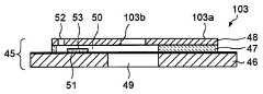
도 9는 혈액 센서의 제2 예의 단면도이다. 도 8에 도시하는 혈액 센서(42)의 저장부(49)의 천장면(49a)은 봉쇄되어 있는 한편, 도 9에 도시하는 혈액 센서(103) 의 저장부(49)의 천장면은 개방되어 있다.9 is a sectional view of a second example of a blood sensor. The
혈액 센서(103)의 커버(48)에는 구멍(103b)이 형성된다. 구멍(103b)의 직경(예를 들면, 1.0㎜)은 저장부(49)의 직경(예를 들면, 2.0㎜)보다 작은 직경이고, 공기 구멍(52)의 직경(50㎛ 내지 250㎛)보다 큰 것이 바람직하다. 구멍(103b)은 저장부(49)의 천장면 중앙에 위치하는 것이 바람직하다. 레이저는 구멍(103b)을 통과하여 피부를 천자한다. 구멍(103b)을 마련함으로써, 레이저의 감쇠를 억제할 수 있다. 따라서, 조사하는 레이저의 에너지를 작게 할 수 있다.The
구멍(103b)은 공기 구멍(52)과 함께 부압 수단(34, 140)이 저장부(49)를 부압으로 하기 위한 부압 경로가 될 수 있다.The
도 10에 도시하는 바와 같이, 구멍(103b)의 내측에 발생하는 혈액(16)의 표면장력은 피부 천자에 의해 채취한 혈액(16)이 커버 상면으로 유출되는 것을 억제한다. 혈액(16)은 저장부(49)의 내부에 널리 퍼진다. 따라서, 적정량의 혈액(16)을 채취할 수 있다. 저장부(49)를 채운 혈액(16)은 모세관 현상에 의해 공급로(50)로 유입된다.As shown in FIG. 10, the surface tension of the
구멍(103b)을 발수성으로 해 두면 혈액(16)은 구멍(103b)으로부터 흘러넘치기가 더욱 어려워진다. 따라서, 혈액 검사 장치(31, 31a)의 내부가 혈액으로 오염되지 않는다.When the
혈액 센서(103) 커버(48)의 재질은 폴리에틸렌 테레프탈레이트(PET) 등을 사용할 수도 있고, 기판(46)이나 스페이서(47)와 마찬가지의 재질을 사용할 수도 있다. 따라서, 재료 관리가 용이하다.The material of the
레이저광은 저장부(49)의 구멍(103b)을 통과하지만, 구멍(103b)의 중심을 통과해도 되고, 구멍(103b)의 중심에서 벗어난 위치를 통과해도 무방하다. 예를 들면, 레이저광을 구멍(103b)의 중심으로부터 공급로(50)에서 먼 위치를 통과시키면, 피부(13)로부터 유출된 혈액(16)이 확실하게 저장부(49)의 내부를 채운 다음 공급로(50)로 유입된다. 따라서, 정밀도가 높은 측정이 가능하다.Although the laser beam passes through the
혈액 센서(103)는 미리 저장부(49)의 천장면에 구멍(103b)이 형성되어 있다. 이와 같이 구멍(103b)이 미리 형성되어 있으므로 천공해야 할 부분에 레이저의 축을 맞출 필요가 없다. 따라서, 혈액 센서 유닛(44)에 혈액 센서(103)를 장착하는 것이 쉬워진다. 구멍(103b)은 0.05 내지 0.25㎜ 정도로 작게 하면 되고, 천자공으로부터의 혈액(16) 유출을 억제하는 것이 바람직하다.The
본 발명의 혈액 검사 장치(31, 31a)에서의 혈액 센서(42, 103)는, 도 8 및 도 9에 도시한 바와 같이, 저장부(49)와 공급로(50)를 갖는 것이 바람직하다. 공급로(50)의 내벽면은 친수성을 갖는 것이 바람직하다. 검출부(51)가 배치된 공급로(50)에 혈액을 순조롭게 보내기 위함이다. 또한, 공급로(50)의 내벽면의 친수성은 저장부(49)의 내벽면의 친수성보다 강한 것이 바람직하다. 저장부(49)에 저장된 혈액을 순조롭게 공급로(50)에 공급하기 위함이다.It is preferable that the
또한, 본 발명의 혈액 검사 장치(31, 31a)에서의 혈액 센서(42, 103)는, 도 8 및 도 9에 도시한 바와 같이 커버(48)를 갖고, 커버(48)는 저장부(49)의 천장면을 형성한다. 커버(48)의 상면(48a, 103a)(레이저가 조사되는 면)은 발수성을 갖는 것이 바람직하다. 또한, 커버(48)의 상면(48a, 103a)의 발수성은 저장부(49)의 내 벽면의 발수성보다 강한 것이 바람직하다. 저장부(49)에 저장된 혈액이 커버(48)에 형성된 구멍(레이저 천공에 의한 구멍 또는 구멍(103b))으로부터 유출되는 것을 방지하기 위함이다.In addition, the
혈액 센서의 제3 예Third example of blood sensor
환자 피부(13)의 습한 정도는 환경에 따라 다르다.The degree of humidity of the patient's
한편, 레이저에 의해 천자된 피부(13)는 적당한 수분을 갖고 있는 것이 바람직하다. 따라서, 레이저 천자하기 전에 피부(13)의 근방을 미리 적셔 둠으로써, 피부(13)에 적당한 수분을 주어 습한 정도를 일정하게 하는 것이 바람직하다. 안정된 조건으로 측정을 행하기 위함이다.On the other hand, the
도 11에는 혈액 센서(42)(상세는 도 8을 참조)가 피부(13)에 맞닿는 하면측에 물을 저장하는 물 저장부(195)를 마련한 혈액 센서(42a)가 도시된다. 도 11에 도시한 혈액 센서(42a)는 레이저광이 조사되었을 때 또는 레이저광이 조사되기 전에 부압 수단(34, 140)에 의해 피부가 솟아올랐을 때에 물 저장부(195)가 터져 피부(13)에 정량의 물을 끼얹어 피부를 적실 수 있다. 물 저장부(195)는, 예를 들면 물이 담긴 PET 등의 플라스틱재의 용기이거나, 더 부드러운 백이라도 가능하며, 물을 흡수시킨 스펀지 또는 면상(綿狀)의 부재라도 무방하다. 단, 레이저광이 통과하는 투과 부분(196)에는 물 저장부(195)를 배치하지 않는 것이 바람직하다. 물에 의해 레이저광의 강도가 감소하기 때문이다.11 shows a
혈액 센서의 투시 평면도 1Perspective top view of
도 12는 혈액 센서(42)의 투시 평면도이다. 혈액 센서(42)에는 검출 전극(54 내지 57)이 배치되며, 저장부(49)로부터 공기 구멍(52)을 향해 차례로 검출 전극(57)(Hct(헤마토크리트)극), 검출 전극(56)(대극), 검출 전극(54)(작용극), 검출 전극(56)(대극), 검출 전극(55)(검지극)이 된다. 검출부(51)에 검출 전극(54 내지 56)이 배치된다.12 is a perspective plan view of the
검출 전극(54 내지 57)의 각각은 접속 전극(54a 내지 57a)에 접속된다. 접속 전극(54a 내지 57a)은 기판(46)의 외주까지 연장된다. 접속 전극(54a 내지 57a)의 각각에는 접촉 부위(54b 내지 57b)가 형성된다. 또한, 접속 전극(56a)에는 접촉 부위(56b) 외에 접촉 부위(56c)도 형성되어 2개의 접촉 부위가 형성되어 있다. 기준 전극(56d)은 접속 전극(56a) 이외의 접속 전극(54a, 55a, 57a)에 마련해도 상관없다.Each of the
접촉 부위(54b 내지 57b) 및 접촉 부위(56c)는 센서(42)의 외주 근방에 대략 등간격으로 배치된다.The
각 접촉 부위(54b 내지 57b, 56c) 중 접촉 부위(56b)와 접촉 부위(56c)는 도통하고 있으며, 그 외의 접촉 부위끼리는 절연되어 있다.Of the
접촉 부위(56c)를 기준 접촉 부위, 즉 기준 전극(56d)으로서 이용하여 각 접속 전극을 특정할 수 있다. 즉, 인접하는 접촉 부위의 절연 저항을 전기 회로부(36)(도 2 참조)에서 측정하여 절연 저항이 영이 되는 접촉 부위를 기준 전극(56d)으로 특정한다. 기준 전극(56d)을 기준으로, 시계 방향으로 접속 전극(56a), 접속 전극(57a), 접속 전극(54a), 접속 전극(55a)을 특정한다.Each connection electrode can be specified using the
이와 같이 혈액 센서(42)는 기준 전극(56d)을 가지므로 각 접속 전극을 특정 할 수 있다. 따라서, 장치 본체(39)에 배치된 5개의 커넥터 각각에 접촉 부위(54b 내지 57b, 56c)가 임의로 접속되더라도 각 접속 전극이 특정되어 측정이 가능해진다. 따라서, 혈액 센서(42)(또는 혈액 센서(42)를 포함하는 혈액 센서 유닛(44))를 대칭형으로 하여 간단하게 장치 본체(39)에 장착할 수 있어 장착 작업이 매우 쉬워진다.Thus, since the
기판(46)의 외주 상에는 위치 맞춤 오목부(46c)를 마련해도 된다. 위치 맞춤 오목부(46c)에 대응하여, 스페이서(47)와 커버(48)의 각각 외주 상에는 위치 맞춤 오목부(47c, 48c)가 마련된다. 위치 맞춤 오목부(46c 내지 48c)에 의해 혈액 센서(42)를 혈액 센서 유닛(44)의 소정 위치에 맞추어 장착할 수 있다.On the outer periphery of the board |
혈액 센서의 투시 평면도 2Perspective top view of the
도 13은 원형 형상의 혈액 센서의 투시 평면도이다. 도 13에 도시한 혈액 센서(101)는 접속 전극(56a)으로부터 소정의 패턴을 통해 기준 전극(56d)을 형성한 점에서 혈액 센서(42)(도 12 참조)와 다르다. 이하에서, 이 차이점을 중심으로 설명한다.Fig. 13 is a perspective plan view of a circular blood sensor. The
기준 전극(56d)에는 기준 접촉 부위(56c)가 형성된다. 기준 접촉 부위(56c) 및 접촉 부위(54b 내지 57b)는 각각 외주 근방에 등간격으로 배치된다. 즉, 접촉 부위(54b, 55b, 56b, 56c, 57b)로 정오각형을 형성하고 있다.The
접속 전극(56a)과 기준 전극(56d)의 사이는 레이저로 가공된 패턴(56e)으로 접속된다. 패턴(56e)의 폭을 바꿈으로써 접촉 부위(56b)와 기준 접촉 부위(56c) 사이의 저항값을 변화시킬 수 있다. 기준 전극(56d)은 접속 전극(54a 내지 57a)의 위 치를 특정하는 기준이 된다.The
기준 전극(56d)은 혈액 센서(101)의 제품 사양의 식별에 이용될 수 있다. 예를 들면, 패턴(56e)의 저항값이 200 오옴 내지 1000 오옴이면 검량선 1을, 저항값이 1000 오옴 내지 2000 오옴이면 검량선 2를, 저항값이 2000 오옴 내지 3000 오옴이면 검량선 3을 각각 이용한다고 설정하고, 자동으로 그 센서의 검량선을 인식하여, 최적인 검량선을 이용하여 혈당치를 측정한다.The
기준 전극은 검량선의 자동 인식 외에도 여러 가지 제품 사양의 식별에 대해 이용될 수 있다. 예를 들면, A사 사양, B사 사양과 같이, 출하처의 사용자의 식별에 이용될 수도 있다.Reference electrodes can be used for identification of various product specifications in addition to automatic recognition of calibration curves. For example, like the company A specification and the company B specification, it may be used for identification of the user of the shipping destination.
패턴(56e)에서 여러 가지 값을 갖는 인덕터를 형성하고, 이 인덕터를 발진기를 구성하는 공진기에 접속하여, 인덕터의 값의 차이에 의해 발진 주파수를 변화시켜 여러 가지 정보를 갖게 할 수 있다.In the
기준 전극(56d)을 마련함으로써 혈액 센서 유닛(44)을 혈액 검사 장치(31, 31a)에 장착할 때, 장착 방향을 축으로 하는 축 둘레의 각도를 임의로 하여 장착해도 각 접속 전극(54a 내지 57a)을 특정할 수 있다. 따라서, 혈액 센서 유닛(44)의 장착에 있어서 장착 방향을 육안 등으로 맞출 필요가 없어 장착이 쉬워진다.When the
혈액 센서의 투시 평면도 3Perspective top view of the
도 14는 사각 형상을 한 혈액 센서의 투시 평면도이다. 도 14에 도시한 혈액 센서(102)의 외형 형상은 사각형이지만, 육각형이나 팔각형 등의 다각형이라도 무방하다. 사각형이나 육각형으로 하면 재료 선택의 수율이 향상한다. 또한, 도 14에 도시한 바와 같이, 사변 중 한 변에 혈액 센서 유닛(44)과의 위치 맞춤 오목부(102a)를 마련하여 비대칭형으로 해도 된다. 오목부(102a)는 혈액 센서(102)를 혈액 센서 유닛(44)에 장착할 때의 기준이 된다. 또한, 오목부(102a)에 계합하는 혈액 센서 유닛(44) 측의 볼록부(130f)(도 25 참조)를 기준으로 하여 어댑터(40)와의 위치를 맞추면, 기준 전극(56d)을 마련하지 않아도 접속 전극(54a 내지 57a)의 위치를 특정할 수 있다.14 is a perspective plan view of a blood sensor having a rectangular shape. Although the external shape of the
접촉 부위(54b 내지 57b)는 사각형의 기판(102b)의 각 모퉁이에 형성되어 있다. 기판(102b)에는 스페이서(102c) 및 커버(102d)가 접합된다. 기판(102b)은 기판(46)에 대응하고, 스페이서(102c)는 스페이서(47)에 대응하고, 커버(102d)는 커버(48)에 대응한다(도 8 참조).Contact
혈액 센서의 분해 평면도Exploded top view of blood sensor
본 발명의 혈액 검사 장치(31, 31a)에 구비되는 혈액 센서(42)(도 8 참조)의 조립 및 재료에 대해 설명한다.The assembly and material of the blood sensor 42 (refer FIG. 8) with which the
도 15는 혈액 센서(42)의 분해 평면도이다. 도 15의 (a)는 커버(48)의 평면도, (b)는 스페이서(47)의 평면도, (c)는 기판(46)의 평면도이다.15 is an exploded plan view of the
도 15의 (c)는 혈액 센서(42)를 구성하는 원형 기판(46)의 평면도이다. 기판(46)의 직경은 약 8.0㎜로 하면 된다. 기판(46)의 재질은 폴리에틸렌 테레프탈레이트(PET) 등의 수지이며, 두께는 약 0.075 내지 0.250㎜(예를 들면, 0.188㎜)이다.15C is a plan view of the
기판(46)의 상면에는 검출 전극(54 내지 57) 및 검출 전극(54 내지 57)의 각 각으로부터 도출된 접속 전극(54a 내지 57a)이 일체적으로 형성된다. 검출 전극 및 접속 전극은 금이나 백금, 팔라듐 등을 재료로 하여, 스퍼터링법 또는 증착법에 의해 도전층을 형성하고 레이저 가공하여 형성하면 된다.On the upper surface of the
기판(46)의 대략 중앙에 형성된 구멍(46a)의 직경은 약 2.0㎜로 하면 된다. 구멍(46a)의 벽면은 공급로(50)보다 약한 친수성을 갖거나 커버(48)의 상면(48a)보다 약한 발수성을 갖는 것이 바람직하다.What is necessary is just to make the diameter of the
구멍(46a)은 검출 전극(54 내지 57) 측에서 볼록 금형을 이용하여 펀칭하여 형성하는 것이 바람직하다. 검출 전극(54 내지 57) 측에서 펀칭하면, 검출 전극(54 내지 57)에 상처가 나지 않기 때문이다. 또한, 펀칭에 의해 구멍(46a)에 버(burr)가 생겼다고 해도 그 버는 하방(피부측)을 향한다. 따라서, 저장부(49)로부터의 혈액(16)의 유출이 방지된다. 기판(46)의 외주 상에 마련된 위치 맞춤용의 오목부(46c)는 혈액 센서 유닛(44)의 통체(41e)에 형성된 위치 맞춤용 볼록부(41j)(모두 도 16 참조)와 맞물린다. 따라서, 혈액 센서(42)의 혈액 센서 유닛(44)에의 장착 위치가 결정된다.It is preferable to form the
도 15의 (b)는 스페이서(47)의 평면도이다. 스페이서(47)의 직경은 약 5.2㎜로 하면 된다. 스페이서(47)의 재질은 폴리에틸렌 테레프탈레이트 등의 수지이면 되고, 그 두께는 0.025 내지 0.25㎜(예를 들면, 0.1㎜)이면 된다.15B is a plan view of the
스페이서(47)의 대략 중앙에 형성된 구멍(47a)은 직경 2.0㎜이며, 기판(46)에 형성된 구멍(46a)에 대응하는 위치에 형성된다. 구멍(47a)의 벽면은 공급로(50)보다 약한 친수성을 갖거나 커버(48)의 상면(48a)보다 약한 발수성을 갖는 것이 바 람직하다. 저장부(49)는 구멍(46a)과 구멍(47a)으로 형성된다.The
구멍(47a)으로부터 외주 방향을 향해 슬릿(47b)이 형성된다. 슬릿(47b)은 혈액의 공급로(50)가 된다. 슬릿(47b)의 벽면과 그에 대응하는 기판(46)의 상면도 친수화 처리되어 있다. 또한, 슬릿(47b)의 폭은 약 0.6㎜로 하면 되고, 길이는 약 2.4㎜로 하면 된다. 그 결과, 공급로(50)의 용량은 약 0.144μL가 된다.The
따라서, 공급로(50)의 용량을 작게 하면 소량의 혈액으로 혈액 검사를 할 수 있으므로 환자의 부담도 적고 또한 환자에게 미치는 공포심도 없다.Therefore, if the dose of the
스페이서(47)의 외주 상에 마련된 위치 맞춤용의 오목부(47c)는 기판(46)에 형성된 위치 맞춤용의 오목부(46c)에 대응한 위치에 형성된다.The
도 15의 (a)는 커버(48)의 평면도이다. 커버(48)의 직경은 약 5.2㎜로 하면 된다. 커버(48)의 두께는 약 0.050 내지 0.125㎜(예를 들면, 0.075㎜)로 하면 된다.15A is a plan view of the
커버(48)의 재질은 레이저광을 흡수하지 않는 재질로 할 수 있다. 커버(48) 재질의 예는 유리나 폴리이미드 등의 플라스틱이 포함된다. 레이저광이 커버(48)에서 흡수되지 않으면 저장부(49)의 천장면(49a)을 통과하여 피부를 천자할 수 있다. 레이저광에 의해 천장면(49a)이 천공되지 않기 때문에 혈액이 구멍으로부터 유출되지 않아 장치 본체(39)의 내부에 혈액(16)이 유입되지 않는다.The material of the
커버(48)의 재질은 레이저광을 흡수하는 재질이라도 무방하다. 그 경우에는, 조사된 레이저광에 의해 커버(48)가 천공되거나 레이저광을 조사하기 전에 커버(48)에 레이저광이 관통하기 위한 구멍을 형성해 두면 된다.The material of the
공기 구멍(52)은 공급로(50)의 선단부에 대응하여 형성된다. 공기 구멍(52)의 직경은 50㎛이다.The
기체(45)의 상면을 형성하는 커버(48)의 상면(48a)(도 8 참조)은 발수화 처리되어 있는 것이 바람직하다. 공급로(50)의 천장면은 친수화 처리되어 있는 것이 바람직하다. 또한, 저장부(49)의 천장면(49a)은, 공급로(50)보다 약하게 친수화 처리되어 있거나 커버(48)의 상면(48a)보다 약하게 발수화 처리되어 있는 것이 바람직하다.It is preferable that the
친수성을 약하게 하려면, 예를 들면, 소수성 재료에 실시된 친수화재를 제거하여 소수성을 강하게 하면 된다. 친수화재의 제거는 예를 들면 UV(자외선) 조사에 의해 친수화재를 분해하여 행한다. 저장부(49)의 천장면(49a)은 소수성의 소재를 그대로 이용할 수 있다.To weaken the hydrophilicity, for example, the hydrophilic material applied to the hydrophobic material may be removed to strengthen the hydrophobicity. The hydrophilic fire is removed by, for example, decomposing the hydrophilic fire by UV (ultraviolet) irradiation. The
재료의 발수화는 그 재료에 발수화재를 혼입하면 된다. 또한, 친수성 재료의 표면에 적당량의 발수화재를 도포하여도 된다. 한편, 발수성의 정도를 조정하려면, 혼입하는 발수화재의 양을 조정하면 된다.The water repellent of the material may be mixed with the water repellent material. In addition, an appropriate amount of water repellent material may be applied to the surface of the hydrophilic material. On the other hand, in order to adjust the degree of water repellency, what is necessary is just to adjust the quantity of the water repellent material mixed.
혈액 센서(42)의 각 부재의 친수성 또는 소수성은 이하와 같이 하여 조정할 수 있다.The hydrophilicity or hydrophobicity of each member of the
커버(48)의 상면(48a)에 미리 발수화 처리를 행한다. 한편, 커버(48)의 하면에는 친수화 처리를 전면에 실시한다. 커버(48)의 하면에는 공급로(50)의 천장면이 포함된다. 다음으로, 기판(46)과 스페이서(47)와 커버(48)를 접합한다. 이들을 접합한 다음 저장부(49)의 개구로부터 단파장의 UV를 조사하여 천장면(49a)의 친수성 재료를 분해 제거한다.The water repellent treatment is performed on the
이상과 같이 제조된 혈액 센서(42)는 커버(48)의 상면(48a)을 발수성으로 하고, 공급로(50)의 내면을 친수성으로 할 수 있다. 또한, 저장부(49)의 내면은 공급로(50)보다 약한 친수성 또는 상면(48a)보다 약한 발수성을 가질 수 있다.The
기판(46)의 두께(0.188㎜)와 스페이서(47)의 두께(0.100㎜)와 커버(48)의 두께(0.075㎜)의 비는 대략 2.5:1.3:1로 되어 있다. 이에 따라, 혈액 센서(42)를 박형화하면서 게다가 충분한 혈액을 모으는 저장부(49)를 형성할 수 있다. 또한, 스페이서(47)의 두께(0.100㎜)에 의해 공급로(50)의 모세관 현상의 효과도 충분히 얻을 수 있다.The ratio of the thickness of the substrate 46 (0.188 mm) to the thickness of the spacer 47 (0.100 mm) and the cover 48 (0.075 mm) is approximately 2.5: 1.3: 1. As a result, it is possible to form the
혈액 센서(42)의 저장부(49)의 용적(0.904μL)과 공급로(50)의 용적(0.144μL)의 비는 대략 6:1로 하면 되지만, 특별히 한정되지는 않는다. 그에 따라, 혈액(16) 부족에 의해 검사가 부정확하게 되는 일은 없다. 또한, 저장부(49)의 용적은 필요로 하는 공급로(50)의 용적에 대해 너무 크지는 않아, 혈액(16)이 대량으로 공급로(50)로 흘러 시약(53)(도 8 참조)을 밀어 흘러가게 하지도 않는다. 따라서, 혈액(16)의 흐름이 율속(律速) 상태가 되어 시약(53)의 용융성에 격차가 생기지 않아 정확한 혈액(16) 검사를 할 수 있다.The ratio of the volume (0.904 μL) of the
또한, 채취하는 혈액(16)의 양은 혈액(16)의 검사에 필요 충분한 미소 용량으로 설정된 것으로서 공급로(50) 용적의 약 6배의 혈액(16)을 채취할 뿐이다. 따라서, 환자에게 미치는 부담을 극히 줄일 수 있다. 정확한 측정을 위한 혈액(16)의 채취량과 환자의 부담을 줄이기 위한 혈액(16)의 채취량을 감안하여 저장부(49)의 용적은 공급로(50) 용적의 5배 이상이고 7배 이하인 것이 바람직하다.In addition, the amount of
혈액 센서 유닛에 대해About blood sensor unit
본 발명의 혈액 검사 장치(31, 31a)에서의 혈액 센서(42)는 혈액 센서 유닛(44)에 포함되어 있어도 무방하다. 혈액 센서 유닛(44)은 장치 본체(39)에 탈착 가능하고 교환 가능한 부재이다.The
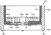
도 16은 혈액 센서 유닛(44)과 그 근방의 단면도이다. 혈액 센서 유닛(44)은 상하 방향이 모두 개구된 원통 형상의 홀더(41)와 홀더(41) 내를 막듯이 형성된 장착부(41b)에 의해 단면이 "H"자 형상으로 구성된다.16 is a cross-sectional view of the
홀더(41)의 재질은 사출 성형할 수 있는 수지가 바람직하고, 예를 들면 ABS 수지나 AS 수지, 폴리에틸렌, 폴리프로필렌, 폴리염화비닐, 폴리에틸렌 테레프탈레이트 등의 열가소성 수지, 또는 페놀 수지나 에폭시 수지, 실리콘 수지 등의 열경화성 수지 등이 예시된다.The material of the
장착부(41b)에는 혈액 센서(42)가 장착된다. 혈액 센서(42)는 탈착 가능해도 된다. 도 16에서는 혈액 센서(42)가 장착부(41b)의 상측(레이저 발사 장치(33)측)에 장착되어 있지만, 장착부(41b)의 하측(천자되는 피부(13)측)에 장착되어도 무방하다.The
장착부(41b)의 중앙에는 저장부(49)에 대응하여 창(43)을 마련하는 것이 바람직하다. 창(43)의 개구부 면적은 저장부(49)의 개구부 면적보다 큰 것이 바람직하다. 또한, 장착부(41b)의 상측과 하측을 관통하는 부압로(41c)가 마련된다. 부압로(41c)는 예를 들면 혈액 센서(42)의 외주와 홀더(41)의 내주측 사이에 마련되면 된다.It is preferable to provide a
장착부(41b)보다 하측의 통체(41d)는 피부(13)와의 사이에 부압실(60)을 형성한다. 또한, 혈액 센서 유닛(44)의 장착부(41b)보다 상측의 통체(41e) 내벽은 어댑터(40)의 외측에 걸린다.The
어댑터(40)의 내측에는 커넥터(61)가 마련된다. 커넥터(61)는 각각 독립적인 복수 개(예를 들면, 5개)의 커넥터(61a 내지 61f)로 이루어진다. 혈액 센서 유닛(44)을 어댑터(40)에 장착하면, 커넥터(61a 내지 61f)가 혈액 센서(42)의 접촉 부위(54b 내지 57b, 56c)의 각각에 접촉한다. 커넥터(61a 내지 61f)의 신호는 전기 회로부(36)로 유도된다.The
통체(41d)의 선단(41h)에 마련된 제1 피부 접촉 센서(62)는 혈액 센서 유닛(44)이 피부(13)에 맞닿은 것을 검지한다. 제1 피부 접촉 센서(62)도 홀더(41) 내에 배치된 도체(62a)를 통해 어댑터(40)에 마련된 접속부(62c)에 접속하고, 또한 어댑터(40) 측의 도체(62b)에 접속한다. 도체(62b)는 전기 회로부(36)로 유도된다.The first
통체(41d) 선단(41h)의 서로 다른 부위(도 16에서는 통체(41d)의 중심을 지나는 직선상)에 복수 개(예를 들면, 2개)의 도체로 이루어지는 제1 피부 접촉 센서(62)를 마련하는 것이 바람직하다. 제1 피부 접촉 센서(62)의 2개의 도체 사이의 저항값을 측정함으로써 피부(13)에 맞닿은 것을 검지한다. 이 때문에, 피부(13)가 틈새 없이 확실하게 혈액 센서 유닛(44)의 선단에 맞닿은 것을 검지할 수 있다. 제1 피부 접촉 센서(62)가 피부의 접촉을 검지하지 않는 한 레이저광을 발사할 수 없게 하는 것이 바람직하다. 제1 피부 접촉 센서(62)는 기구식의 마이크로 스위치나 반사형의 광학 스위치 등이라도 된다.First
레이저 발사 장치(33)로부터 레이저광이 발사되면 레이저광에 의해 피부(13) 내의 모세혈관이 손상되어 혈액(16)이 유출된다. 유출된 혈액(16)은 저장부(49)에 고인다.When the laser light is emitted from the
혈액 센서 유닛(44)의 통체(41d)와 어댑터(40)에는 혈액 센서 유닛(44)의 장착을 용이하게 하기 위한 가이드부가 마련되어도 된다. 도 17은 혈액 센서 유닛(44)의 어댑터(40)에의 삽입을 안내하는 가이드부(63)의 주요부 전개 정면도이다. 통체(41d) 내측에 볼록부(41f)가 형성되고, 어댑터(40)의 외측에 볼록부(40f)가 형성된다. 볼록부(41f) 및 볼록부(40f)의 일단의 선단부(41g) 및 선단부(40g)는 각각 예각으로 되어 있다. 선단부(41g) 및 선단부(40g)는 서로 대향한다. 볼록부(40f)와 그 선단부(4Og), 및 볼록부(41f)와 그 선단부(41g)로, 가이드부(63)를 형성한다.The
혈액 센서 유닛(44)을 어댑터(40)에 삽입할 때 서로의 위치가 다소 어긋나더라도, 혈액 센서 유닛(44)은 가이드부(63)를 따라 진로를 수정하면서 삽입된다(화살표 64 참조). 그 결과, 어댑터(40)에 마련된 커넥터(61a 내지 61f)와 센서(42)에 형성된 접촉 부위(54b 내지 57b, 56c)의 어느 하나가 확실히 접촉한다. 따라서, 혈액 센서 유닛(44)을 삽입 방향을 축으로 하는 회전 각도를 고려하지 않고 삽입할 수 있으므로 혈액 센서 유닛(44)의 장착이 용이해진다.Even when the positions of the
도 18은 혈액 센서 유닛의 사시도이다. 도 18에 도시한 혈액 센서 유닛(110)은 특별한 설명이 없는 한 혈액 센서 유닛(44)과 동일한 구조로 하면 된다. 혈액 센서 유닛(110)은 그 단면이 "H"자 형상인 원통형이다. 혈액 센서 유닛(110)의 홀더(110a)의 내측에는 혈액 센서(혈액 센서(42, 101, 102, 103)의 어느 것이라도 무방함)의 접촉 부위의 신호를 전기 회로부(36)로 전달하는 5개의 커넥터(111)가 마련되어 있어도 된다(단, 혈액 센서(102)의 경우에는 4개의 커넥터라도 무방하다). 커넥터(111)는 홀더(110a)의 상단에서 어댑터(40)에 접속하고 이 어댑터(40)를 통해 전기 회로부(36)로 유도된다.18 is a perspective view of a blood sensor unit. The
커넥터(111)를 어댑터에 마련하여 커넥터(111)를 혈액 센서 유닛(110)의 혈액 센서의 접촉 부위에 접촉시켜도 무방하다.The
홀더(110a)의 개구를 막듯이 마련된 장착부(110b)의 뒤측(하단(110h)측, 즉 천자되는 피부가 배치되는 측)에 혈액 센서(42)가 장착된다. 장착부(110b)의 대략 중앙에 마련된 창(110c)은 혈액 센서(42)의 저장부(49)의 위치에 대응하여 형성된다. 레이저는 창(110c)과 저장부(49)를 통과하여 피부(13)를 천자한다.The
장착부(110b)에 마련된 공기 구멍(110d)은 혈액 센서(42)의 공기 구멍(52)에 대응하는 위치에 형성된다. 공기 구멍(110d)은 혈액 센서(42)의 공급로(50)에 혈액(16)을 유입시키거나 저장부(49)에 부압을 인가하기 위해 형성된다.The
어댑터(40)와 계합하는 계합부(110e)의 탄성으로 어댑터(40)에 혈액 센서 유닛(110)이 계합한다. 홀더(110a)에는 서로 대향하는 2개의 계합부(110e)가 마련된다. 계합부(110e)는 그 양 옆에 슬릿이 형성되어 탄성이 부여되고, 홀더(110a)와 일체적으로 마련된다. 따라서, 계합부(110e)를 낮은 가격으로 제조할 수 있다.The
장착부(110b)의 상면에는 소취(消臭) 부재 비치부(110f)가 동심원 형상으로 마련된다. 소취 부재 비치부(110f)에는 소취 부재가 놓여진다. 레이저 천자를 한 경우, 피부(13)가 탄화하여 냄새가 발생하는 경우가 있으므로 이 냄새를 소취 부재(탈취제 등)로 소취할 수 있다. 또한, 장착부(110b)의 상면에는, 혈액 고임부(110g)가 동심원 형상으로 마련된다. 따라서, 혈액 센서(103)(도 10 참조)의 구멍(103b)으로부터 혈액(16)이 넘쳐 나오더라도, 혈액(16)이 혈액 고임부(110g)에 고이므로 혈액(16)이 혈액 검사 장치(31, 31a)의 본체부를 더럽히는 것을 방지할 수 있다.On the upper surface of the mounting
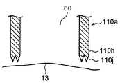
도 19는 홀더(110a)의 하단(110h) 근방의 일 구성예를 도시하는 주요부 단면도이다. 하단(110h)의 단부는 환자의 피부(13)에 맞닿아 부압실(60)을 형성한다. 하단(110h)은 피부(13)와의 밀착성이 요구된다. 따라서, 하단(110h)은 예각으로 뾰족한 2개의 동심원 상의 선(110j)으로 형성되어도 된다. 선(110j)은 피부(13)와 선접촉에 의해 확실히 맞닿으므로 부압실(60)의 밀실성은 유지된다. 선(110j)은 2개일 필요는 없고 하나라도 2개 이상의 복수 개라도 무방하다.FIG. 19 is a sectional view of principal parts showing a configuration example near the
또한, 2개의 동심원 상의 선(110j)의 사이에 형성되는 홈에 모세관 기능을 부여하면 측정 후의 여분의 혈액(16)은 상기 홈에 흡인된다. 따라서, 닦아내기 위한 종이 등을 준비할 필요가 없다.In addition, when the capillary function is applied to the groove formed between two concentric circles 110j, the
도 20은 홀더(110a)의 하단(110h) 근방의 다른 구성예를 도시하는 주요부 단면도이다. 하단(110h)에는 고무나 실리콘, 우레탄, 스펀지 등의 탄성체로 형성된 동심원 형상의 접촉부(110k)가 형성된다. 따라서, 접촉부(110k)는 그 탄성에 의해 피부(13)와 밀착하여 부압실(60)의 밀실성이 유지된다. 접촉부(110k)의 접촉면은 피부(13)와 맞닿는 면적을 크게 하기 위해 평면인 것이 바람직하다.20 is a sectional view of principal parts showing another example of the configuration near the
접촉부(110k)를 스펀지 등의 흡수성을 갖는 흡수 부재로 형성하면 천자에 의해 유출된 여분의 혈액(16)을 측정 후에 닦아낼 수 있다. 이 때문에, 닦아내기 위한 종이 등을 준비할 필요가 없어진다. 또한, 흡수 부재에 소독약을 가하면 위생적이다.If the
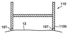
피부(13)의 습한 정도는 계절 등의 외부 환경에 따라 변화한다. 따라서, 천자할 피부(13) 근방의 습한 정도는 일정하게 하는 것이 바람직하다. 따라서, 천자하기 전에 미리 피부(13)에 적당한 수분을 주어 피부를 적셔 둠으로써 안정된 조건에서 측정하도록 해도 된다.The wetness of the
따라서, 도 21에 도시한 바와 같이, 혈액 센서 유닛(110)의 홀더(110a) 하단(110h)의 전체 둘레에 걸쳐 물을 함유시킨 물 저장부(197)를 마련하여 미리 천자부 부근의 피부(13)를 물에 적시고 나서 레이저로 천자하도록 해도 된다. 물 저장부(197)는, 스펀지 등의 탄성을 갖는 다공질 재료이면 된다.Therefore, as shown in FIG. 21, the
도 22는 혈액 센서 유닛(110)의 단면도이다. 도 22에 도시하는 바와 같이, 혈액 센서 유닛(110)의 장착부(110b) 하면에 혈액 센서(42)가 배치되어 장착부(110b)에 의해 보관된다. 피부(13)는 부압 수단(34, 140)(도 2, 도 3 등 참조)에 의해 솟아올라 혈액 센서(42)에 밀착된다. 혈액 센서(42)는 장착부(110b)에 의해 보관되므로 밀착하는 피부(13)에 의해 뒤틀리기 어렵다. 커넥터(111)는 혈액 센서(42)의 접촉 부위(54b 내지 57b, 56c)에 접촉한다. 홀더(110a)에는 어댑터(40)에 대응하는 가이드부(63)(도 17 참조)가 마련되는 것이 바람직하다.22 is a cross-sectional view of the
본 발명의 혈액 검사 장치(31, 31a)는 부압 수단(34, 140)을 갖고, 부압 수단(34, 140)은 혈액 센서 유닛(110)의 내부를 부압으로 한다. 그 부압 경로로서, 혈액 센서 유닛(110)의 장착부(110b)에 홈(110f)을 형성해도 된다. 홈(110f)은 홀더(110a)의 장착부(110b)의 외주측으로부터 장착부(110b)의 대략 중앙에 형성된 창(110e)으로 연장된다. 부압을 인가하면, 홈(110f)도 부압이 되어 혈액 센서(42)가 장착부(110b)에 밀착하고, 부압을 대기 개방하면, 혈액 센서(42)는 장착부(110b)에서 떨어진다.The
커넥터(111)는 혈액 센서(42)와 접촉면(111a)에서 접촉한다. 커넥터(111)는 홀더(110a)에 내장되어 장착부(110b)의 일부에 끼워지듯이 형성된다. 이에 따라, 혈액 센서(42)의 상면에 형성된 접속 전극의 접촉 부위와 커넥터(111)에 마련된 콘택트부(모두 미도시)가 접속된다.The
혈액 센서(42)의 하면에 제2 피부 접촉 센서(110m)를 마련해도 된다. 이에 따라, 부압실(60)의 부압에 의해 피부(13)가 제2 피부 접촉 센서(110m)에 맞닿은 것을 검지한다. 제2 피부 접촉 센서(110m)는, 예를 들면, 대전극으로 구성하면 된다. 제2 피부 접촉 센서(110m)가 피부와의 접촉을 검지하지 않는 한 레이저를 발사할 수 없도록 하는 것이 바람직하다.The second
상기 접촉을 검지한 시점에서 부압 수단(34)에 의한 부압실(60)의 부압을 정지해도 된다. 이와 같이 부압 수단(34)을 제어함으로써 부압 전력을 낭비하지 않고 최적으로 제어할 수 있다.When the contact is detected, the negative pressure in the
또한, 홀더(110a)의 하단(110h)에 제1 피부 접촉 센서(62)를 마련해도 된다.Moreover, you may provide the 1st
도 23은 다른 혈액 센서 유닛의 단면도이다. 도 23에 도시한 혈액 센서 유닛(120)은 특별히 설명이 없는 한 혈액 센서 유닛(110)과 동일한 구조로 하면 된다. 혈액 센서 유닛(120)은 홀더(120a)의 개구를 막듯이 형성된 장착부(120b)의 상측에 혈액 센서(42)가 얹어지는 점에서 혈액 센서 유닛(110)과 다르다. 전기 회로부(36)에 접속되어 있는 커넥터(61)는 혈액 센서(42)의 접촉 부위(54b 내지 57b, 56c)와 도통한다.23 is a sectional view of another blood sensor unit. The
단면 "H"자 형상으로 형성된 혈액 센서 유닛(120)의 장착부(120b)의 상방 공간과 하방 공간은 부압로(120c)로 연통된다. 하방 공간은 부압실(60)을 형성한다. 제1 피부 접촉 센서(62)가 홀더(120a)의 하단(120h)에 마련된다. 또한, 도시하지 않았지만 장착부(120b)의 하면에 제2 피부 접촉 센서(120m)가 마련되어도 된다.The upper space and the lower space of the mounting
혈액 센서(42)를 장착부(120b)의 상면에 장착하면, 커넥터(61)와 혈액 센서(42)의 접촉 부위(54b 내지 57b, 56c)의 접촉압을 크게 할 수 있다. 또한, 혈액 센서(42)의 장착부(120b)에의 장착이 쉬워진다.When the
혈액 센서(42) 및 장착부(120b)로 구분된 장치 본체(39) 측의 공간(도 23 중 상부 공간)과 피부(13) 측의 공간(도 23 중 하방 공간)은 부압로(120c)를 통해 연통된다. 피부(13)에 부압을 인가할 때에는 이 부압로(120c)를 통해 피부(13) 측의 공간을 부압으로 할 수 있다. 또한, 부압을 대기 개방하면, 부압로(120c)를 통해 장치 본체(39) 측의 공간에 공기가 재빠르게 유입된다. 따라서, 혈액 센서(42)에 유입된 혈액이 장치 본체(39) 측으로 비산하는 것을 방지할 수도 있다.The space (upper space in FIG. 23) and the space (downward space in FIG. 23) of the apparatus
부압로로서, 장착부(120b)의 상측에 홈(120f)을 형성해도 된다. 홈(120f)은 홀더(120a)의 장착부(120b)의 외주측으로부터 장착부(120b)의 대략 중앙에 형성된 창(120e)으로 연장된다. 홈(120f)이 있으면 장착부(120b)를 관통하는 구멍을 마련할 필요가 없어진다.As the negative pressure furnace, the
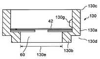
도 24는 또 다른 혈액 센서 유닛의 단면도이다. 도 24에 도시한 혈액 센서 유닛(130)은 특별히 설명이 없는 한 혈액 센서 유닛(44)과 마찬가지의 구조로 하면 된다. 여기에서는, 혈액 센서 유닛(130)의 장착부(130b)의 상면에 센서(42)가 장착된다. 홀더(130a) 하단(130d)의 내경은 상단(130c)의 내경보다 작다.24 is a sectional view of another blood sensor unit. The
장착부(130b)의 하방에 형성되는 부압실(60)의 개구부(130e)의 직경은 2 내지 20㎜가 바람직하고, 3 내지 1O㎜가 보다 바람직하고, 5 내지 7㎜가 더욱 바람직하다. 천자하는 피부에의 부압 효율을 높이기 위함이다. 또한, 상단(130c)의 외형보다 하단(130d)의 외형을 작게 하면 복수의 혈액 센서 유닛(130)을 세로로 적층하여 효율적으로 수납할 수 있다. 일반적으로, 혈액 센서(42)는 어느 정도의 크기를 필요로 하므로 상단(130c)의 외형은 작게 하기 힘든 경우가 있다.2-20 mm is preferable, as for the diameter of the
또한, 홀더(130a)의 내측에 혈액 센서(42) 방향으로 돌출하여 형성된 계지 볼록부(130g)는 혈액 센서(42)를 계지하여 홀더(130a)에서 빠지는 것을 방지한다.In addition, the locking
도 25는 혈액 센서 유닛(130)의 평면도이다. 혈액 센서 유닛(130)의 홀더(130a)에는 혈액 센서(42)의 위치 맞춤용 오목부(46c, 47c)(도 15 참조)에 감합하는 볼록부(130f)가 2개 형성되어 있다(대략 120도의 각도). 홀더(130a)의 볼록부(130f)와 혈액 센서(42)의 위치 맞춤용 오목부(46c)로 혈액 센서 유닛(130) 내에서의 혈액 센서(42)의 배치 위치가 결정된다. 혈액 센서(42)가 적절히 배치된 혈액 센서 유닛(130)은 어댑터(40)에 대해 가이드부(63)(도 17 참조)에 의해 소정 위치에 장착된다. 이와 같이 하여, 혈액 센서(42)의 검출 전극(54 내지 57)의 신호가 전기 회로부(36)에 전달된다.25 is a plan view of the
볼록부(130f)는 하나라도 되지만, 그 경우에는 장착부(130b)를 혈액 센서(42)를 감합할 수 있게 하는 구조로 하는 것이 바람직하다.Although one
레이저의 초점에 대해About the focus of the laser
본 발명의 혈액 검사 장치(31, 31a)는 천자 수단으로서 레이저를 이용하고 있어, 장치 본체(39)에는 레이저 발사 장치(33)가 수납된다(도 2 등 참조). 발사된 레이저광은 초점 렌즈에서 집광되어 피부(13)에 조사된다. 본 발명의 혈액 검사 장치(31, 31a)에 있어서, 레이저광은 예를 들면, 혈액 센서(42)의 면의 근방에 집광되는 것이 바람직하다. 전술한 바와 같이, 천자되는 피부(13)는 부압 수단(34, 140)에 의해 흡인되어 혈액 센서(42)에 밀착되므로 혈액 센서(42)의 면의 근방에 집광된 레이저광은 피부(13)를 효과적으로 천자할 수 있다.The
레이저광의 초점은 혈액 센서(42)의 면 위에 있어도 되고, 혈액 센서(42)의 면보다 피부(13) 측에 있어도 되며, 또는 혈액 센서(42)의 면보다 레이저 발사 장치(33) 측에 있어도 된다. 레이저 얼라이먼트 페이퍼(laser alignment paper)(ZAP-IT사 제품: Z-48)를 이용하여, "번 패턴 직경(㎜)"(Y축)과 "레이저 초점에서 천자하고자 하는 대상(천자 대상: 여기에서는 레이저 얼라이먼트 페이퍼)까지의 거리(㎜)"(X축)의 관계를 조사한 결과를 도 26에 나타냈다. "번 패턴(burn pattern) 직경"이란, 레이저광을 조사했을 때에 뚫리는 구멍의 직경이다.The focus of the laser light may be on the surface of the
도 26은, 본 발명의 혈액 검사 장치에 있어서, 레이저광의 초점 위치에서 천자 대상까지의 거리(X축)와 번 패턴 직경(Y축)의 관계를 나타내는 그래프이다.Fig. 26 is a graph showing the relationship between the distance (X axis) and the burn pattern diameter (Y axis) from the focus position of the laser beam to the puncture object in the blood test apparatus of the present invention.
도 26에 나타낸 그래프의 X축에 있어서, 레이저광의 초점 위치가 "0"이다. 마이너스("-") 영역은 레이저광의 초점 위치보다 레이저 발사 장치(33) 측에 천자 대상 위치를 설정하고 있는 경우를 나타내고, 플러스("+") 영역은 레이저광의 초점 위치보다 레이저 발사 장치(33)로부터 먼 측에 천자 대상 위치를 설정하고 있는 경우를 나타낸다.In the X axis of the graph shown in FIG. 26, the focal position of the laser light is "0". The negative ("-") region indicates the case where the puncturing target position is set on the side of the
레이저의 출력 강도는, 60mJ, 80mJ, 100mJ, 120mJ의 4 종류로 하였다. 출력 강도가 클수록 번 패턴 직경이 커지지만, 어떠한 출력 강도에 있어서도, 초점에서 천자 대상까지의 거리(X)와 번 패턴 직경(Y)의 관계는 유사하다.The output intensity of the laser was made into four types of 60 mJ, 80 mJ, 100 mJ, and 120 mJ. The larger the output intensity is, the larger the burn pattern diameter is, but in any output intensity, the relationship between the burner pattern diameter Y and the distance X from the focus to the puncture target is similar.
A존(천자 대상의 근방에 초점을 맞추었을 때)에서는, 천자 대상 위치의 다소의 차이가 있어도 번 패턴 직경은 그다지 변화하지 않는다. 따라서, 확실히 천자할 수 있다. 한편, B존 또는 C존에서는, 천자 대상 위치의 차이에 의해 밴 패턴 직경이 크게 변화한다. 이는 천자 대상 위치와 상대 관계에 있는 레이저광의 초점 위치에 있어서도 말할 수 있다.In zone A (when focusing on the vicinity of the puncture target), the pattern diameter does not change so much even if there are some differences in the puncture target position. Therefore, it can be surely punctured. On the other hand, in the zone B or zone C, the van pattern diameter greatly changes due to the difference in the puncturing target position. This can also be said in the focal position of the laser beam relative to the puncture target position.
즉, 천자 대상 위치가 고정되어 있는 경우 등은, A존(천자 대상의 근방에 초점을 맞추었을 때)에서는, 레이저광의 초점 위치의 다소의 차이가 있어도 번 패턴 직경은 그다지 변화하지 않는다. 따라서, 확실히 천자할 수 있다. 한편, B존 또는 C존은, 레이저광의 초점 위치의 차이에 의해 번 패턴 직경이 크게 변화한다.That is, in the case where the puncturing target position is fixed or the like, in the zone A (when focusing on the vicinity of the puncturing target), even if there is a slight difference in the focal position of the laser beam, the burn pattern diameter does not change very much. Therefore, it can be surely punctured. On the other hand, in the B zone or the C zone, the burn pattern diameter is greatly changed by the difference in the focal position of the laser beam.
번 패턴 직경이 커지도록 레이저광의 초점 위치가 어긋나면, 천자가 이루어 지지 않기 때문에 안전성이 높아진다. 예를 들면, B존에 레이저광의 초점 위치를 맞추어 두면, 천자 대상 위치가 소정 위치에까지 레이저 발사 위치에 근접하지 않는 한 천자되지 않는다. 즉, 부압에 의해 피부가 충분히 흡인되어 솟아오르지 않는 한 천자가 이루어지지 않는다.If the focal position of the laser beam is shifted so that the burn pattern diameter becomes larger, the puncture is not made, so the safety is increased. For example, if the focal position of the laser beam is set in the zone B, the puncture target position will not be punctured unless the puncture target position is close to the laser firing position. That is, puncture is not made unless the skin is sufficiently sucked and raised by the negative pressure.
또한, C존에 레이저광의 초점 위치를 맞추어 두면, 천자 대상 위치가 소정 위치보다 레이저 발사 위치에 가까워지면 천자가 이루어지지 않는다. 즉, 부압에 의해 피부가 필요 이상으로 흡인되어 솟아올라도 천자되지 않는다.In addition, when the focal position of the laser beam is set in the C zone, puncture is not made when the puncture target position is closer to the laser firing position than the predetermined position. That is, even if the skin is sucked out more than necessary by the negative pressure and rises, it does not puncture.
또한, 혈액 센서(42)에 용융되기 쉬운 필름 등을 배치한 경우는 혈액 센서(42)에 초점을 맞추지 않는 것이 좋은 경우가 있다. 필름이 용해되어 레이저의 에너지가 소비되기 때문이다. 따라서, B존 또는 C존에 초점을 맞추는 것이 바람직한 경우도 있다.In addition, when the film etc. which are easy to melt | fuse are arrange | positioned to the
부압실에In the negative pressure chamber 대해 about
본 발명의 혈액 검사 장치(31,31a)는 부압 수단(34, 140)을 갖고, 장치 본체(39)에는 부압 수단(34, 140)의 구성 요소로서 기계식 흡인 펌프(34a)(도 2) 또는 수동식 흡인 펌프(141)(도 3) 등이 수용된다. 부압 수단(34, 140)은 부압실(60)을 부압하여 피천자 부위인 피부(13)를 흡인해 솟아오르게 함으로써 혈액 센서(42)에 밀착시킨다.The
전술한 바와 같이, 부압 수단(34)은 흡인 펌프(34a), 펌프 밸브 유닛(34b) 및 대기 개방 스위치(34c)로 구성된다(도 2 참조). 부압 수단(140)은, 펌프 밸브 유닛(143) 및 대기 개방 스위치(144) 외에 수동 펌프(141) 및 수동 펌프 노브(142) 로 구성된다(도 3 참조). "부압 수단"이라는 용어는, 광의로는, 펌프(흡인 펌프 또는 부압 펌프)나 밸브(부압 밸브 또는 개방 밸브) 등의 외에 부압 경로 등도 포함한다. 또한, 여기에서 "부압 수단을 구동한다"란, 펌프 및 밸브를 구동하는 것을 말하고, "부압을 개방한다"란, 밸브를 열어 외기압(예를 들면, 대기압)을 도입하는 것을 말한다.As described above, the negative pressure means 34 is composed of a
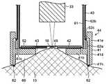
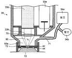
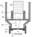
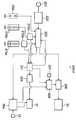
도 27 및 도 28에 부압실(흡인실)과 부압 경로를 도시한다. 도 27은 부압실이 최대인 경우의 부압 경로를 도시하고, 도 28은 부압실이 최소인 경우의 부압 경로를 도시한다. 도 2의 혈액 검사 장치(31)를 예로 들어 설명하면, 도 27에 도시하는 흡인실(60a) 및 도 28에 도시하는 흡인실(60b)은 모두 장치 본체(39)의 내부 공간으로서, 레이저 발사 장치(33)의 레이저 발사구(33c)보다 혈액 센서(42) 측의 공간에 마련된다. 부압실(60)은 측정시에 피부(13)가 혈액 센서 유닛(44)에 맞닿아 부압 상태가 되는 공간을 널리 의미하고, 장치 본체(39) 내의 흡인실(60a, 60b) 외에 혈액 센서 유닛(44)의 내부 공간도 포함된다. 부압실(60)(특히 흡인실(60a, 60b))은, 도 27 및 도 28에 도시하는 바와 같이, 예를 들면, 펌프(34a)에 의해 흡인되고(즉, 부압이 되고), 밸브(34b)에 의해 부압이 해제된다.27 and 28 show a negative pressure chamber (suction chamber) and a negative pressure path. FIG. 27 shows the negative pressure path when the negative pressure chamber is the maximum, and FIG. 28 shows the negative pressure path when the negative pressure chamber is the minimum. Referring to the
부압실(60)을 작게 하면, 부압의 발생에 필요한 에너지가 적어지고, 또한 검사에 필요한 시간도 짧아진다. 따라서, 본 발명의 혈액 검사 장치(31, 31a)의 내부의 부압실(60)(특히 흡인실(60a, 60b))은 레이저 발사 장치(33)의 레이저 발사구(33c)보다 혈액 센서(42) 측에 형성된 벽에 의해 구분되는 것이 바람직하다.When the
구체적으로는, 흡인실(60a, 60b)을 구분하는 벽(부압용 칸막이 또는 격 벽)(70)은 레이저 발사구(33c)와 동일한 위치에 배치되어도 되고, 또는 초점 렌즈(33h)와 동일한 위치에 배치되거나(즉, 벽과 초점 렌즈(33h)가 일체가 되어 있다) 초점 렌즈(33h) 자체가 벽이 되어도 무방하다. 도 27 및 도 28에 각각 도시하는 예는 후자의 경우이다. 또한, 부압실(60)의 용량을 줄이기 위해 흡인실의 형상을 추 형상으로 해도 된다(도 28의 흡인실(60b) 참조). 장치 본체(39)에는 흡인실(60a, 60b)에 연통하는 부압로(71)가 형성되고, 이 부압로(71)는 펌프(34a)의 흡인구에 연결되어 있다. 혈액 센서(42) 내에는, 전술한 바와 같이, 부압 경로(72)로서도 기능하는 저장부(49), 공급로(50) 및 공기 구멍(52)이 마련된다. 흡인실(60a, 60b)은 혈액 센서(42) 내의 이 부압 경로(72)와도 연통하고 있다. 특히, 도 28의 구성예에서는, 흡인실(60b)과 공기 구멍(52)을 연결하는 미세한 부압 경로(73)가 장치 본체(39)에 더 형성된다. 부압 경로(72, 73)(단, 저장부(49)의 부분은 제외함)는 용적이 거의 영에 가까운 미세 유로이다.Specifically, the wall (negative pressure divider or partition wall) 70 which distinguishes the
혈액 검사 장치(31, 31a)에 있어서, 레이저광(80)의 경로 상에 위치하는 내부 공간으로서, 도 29 및 도 30에 도시하는 바와 같이, 크게 나누어 3개의 내부 공간(V1, V2, V3)을 생각할 수 있다. 내부 공간(V1)은 레이저 결정(레이저 로드)(33d)의 전면과 초점 렌즈(33h) 사이의 공간이다. 내부 공간(V2)은 초점 렌즈(33h)와 혈액 센서 유닛(44) 내의 혈액 센서(42)(또는 홀더(41)) 사이의 공간으로서, 도 27 및 도 28의 구성예에서는 장치 본체(39) 내의 흡인실(60a, 60b)에 대응한다. 내부 공간(V3)은 혈액 센서 유닛(44) 내의 혈액 센서(42)(또는 홀더(41))와 피부 접촉 면(74) 사이의 공간으로서, 주로, 혈액 센서 유닛(44)의 내부 공간에 대응한다.Blood test apparatus (31, 31a) according as the inner space positioned on the path of the
예를 들면, 초점 렌즈(33h)의 지름은 φ5 내지 15㎜이다. 초점 렌즈(33h)에서 혈액 센서(42)까지의 거리는 10 내지 30㎜이다. 또한, 혈액 센서(42)에서 홀더(41)의 하면(=피부 접촉면)까지의 거리는 1.5 내지 2㎜이고, 혈액 센서(42) 및 홀더(41)의 지름은 φ6 내지 10㎜이다. 도 27에 도시하는 부압실(60)은 V2와 V3으로 구성되고, 흡인실(60a)의 용적을 최대로 한 경우, 실제로는 장치 본체(39)의 내부 형상은 경사 부분이 거의 없어지기 때문에 V2 부분은 간단하게 원통형에 근사할 수 있고, V3 부분도 마찬가지로 원통형이기 때문에 약 5.5cc의 용량으로 할 수 있다(도 29의 파선으로 둘러싼 영역을 참조). 또한, 도 28에 도시한 부압실(60)도 V2와 V3으로 구성되지만, 흡인실(60b)의 용적을 최소로 한 경우, V2 부분은 원추형이 되어 부압 경로 부분은 무시할 수 있고, V3 부분은 전술한 바와 마찬가지이므로 약 0.45cc의 용량으로 할 수 있다(도 30의 파선으로 둘러싼 영역을 참조).For example, the diameter of the
전기 회로에 대해About electric circuit
도 31은 전기 회로부(36)의 블록도이다. 도 28에 있어서, 참조 부호 54b 내지 57b 및 56c는 혈액 센서(42)에 형성된 접촉 부위이다. 접촉 부위(54b 내지 57b, 56c)는 커넥터(61a 내지 61f)를 통해 전환 회로(71)에 접속된다. 전환 회로(71)의 출력은 전류/전압 변환기(72)의 입력에 접속된다. 전류/전압 변환기(72)의 출력은 아날로그/디지털 변환기(이하, "A/D 변환기"라고 함)(73)를 통해 연산부(74)의 입 력에 접속된다. 연산부(74)의 출력은 액정으로 형성된 표시부(37)에 접속된다. 또한, 전환 회로(71)에는 기준 전압원(78)이 접속된다. 기준 전압원(78)은 그라운드 전위라도 된다.31 is a block diagram of the
제어부(76)의 입출력은 전환 회로(71)의 제어 단자, 연산부(74), 천자 버튼(75), 송신부(77), 타이머(79), 레이저 발사 장치(33), 부압 수단(34)(특히 흡인 펌프(34a)) 및 제1 피부 접촉 센서(62)에 접속되고, 도시하지 않은 경보 수단이나 제2 피부 접촉 센서(110m)(도 22 참조)에도 접속된다. 연산부(74)의 출력은 송신부(77)의 입력에도 접속된다. 부압 수단(34)(특히 펌프 밸브 유닛(34b))의 흡인구는 부압로(71)를 통해 부압실(60)과 혈액 센서 유닛(44)의 내부로 유도된다.The input / output of the
여기에서, 전기 회로부(36)의 동작을 설명한다.Here, the operation of the
혈액 검사 전에 혈액 센서(42)의 접촉 부위(54b 내지 57b, 56c)의 각각이 커넥터(61a 내지 61f) 중 어느 것에 접속되어 있는지를 특정한다. 우선, 제어부(76)의 지령에 의해 커넥터(61a 내지 61f) 중 서로 이웃하는 단자 사이의 전기 저항이 영인 접촉 부위(56c)를 특정한다. 특정된 접촉 부위(56c)에 접속된 접속 전극을 기준 전극(56d)으로 결정한다. 접촉 부위(56c)에 접속된 커넥터(61)를 기준으로 하고 차례로 접속 전극(56a, 57a, 54a, 55a)에 접속하는 커넥터(61)로 특정한다. 이와 같이 하여, 접속 전극(54a 내지 57a)의 각각에 접속된 커넥터(61)를 특정한다.Before the blood test, it is specified which of the
그 후에 혈액 검사를 행한다. 우선, 전환 회로(71)를 전환하여 혈액 성분량을 측정하기 위한 작용극이 되는 검출 전극(54)을 상기 결정된 커넥터(61)를 통해 전류/전압 변환기(72)에 접속한다. 또한, 혈액(16)의 유입을 검지하기 위한 검지극 이 되는 검출 전극(54)을 상기 결정된 커넥터(61)를 통해 기준 전압원(78)에 접속한다.After that, a blood test is performed. First, the switching
그리고, 검출 전극(54)과 검출 전극(55)의 사이에 일정한 전압을 인가한다. 이 상태에서, 혈액(16)이 검출부(51)에 유입되면 검출 전극(54)과 검출 전극(55)의 사이에 전류가 흐른다. 이 전류는 전류/전압 변환기(72)에 의해 전압으로 변환되고 그 전압치는 A/D 변환기(73)에 의해 디지털치로 변환된다. 이 디지털치는 연산부(74)를 향해 출력된다. 연산부(74)는 이 디지털치에 기초하여 혈액(16)이 충분히 유입된 것을 검출한다.Then, a constant voltage is applied between the
미리 정해진 시간이 경과해도, 검출부(51)에서 혈액(16)이 검출되지 않는 경우나 혈액(16)의 양이 적절하지 않은 경우는 경보 수단을 기동시켜 경보함과 함께 처치의 내용을 표시부(37)에 표시해도 된다.Even when a predetermined time elapses, when the
다음으로, 혈액 성분인 글루코오스를 측정한다. 글루코오스 성분량의 측정은 우선 제어부(76)의 지령에 의해 전환 회로(71)를 전환하여, 글루코오스 성분량의 측정을 위한 작용극이 되는 검출 전극(54)을 커넥터(61)를 통해 전류/전압 변환기(72)에 접속한다. 또한, 글루코오스 성분량의 측정을 위한 대극이 되는 검출 전극(56)을 커넥터(61)를 통해 기준 전압원(78)에 접속한다.Next, glucose which is a blood component is measured. To measure the amount of glucose component, first, the switching
예를 들면, 혈액 중의 글루코오스와 그 산화 환원 효소를 일정 시간 반응시키는 동안은 전류/전압 변환기(72) 및 기준 전압원(78)을 오프로 해 둔다. 그리고, 일정 시간(1 내지 10초) 경과 후에 제어부(76)의 지령에 의해 검출 전극(54)과 검출 전극(56)의 사이에 일정한 전압(0.2 내지 0.5V)을 인가한다. 그리고, 검출 전 극(54)과 검출 전극(56)의 사이에 흐른 전류를 전류/전압 변환기(72)에 의해 전압으로 변환한다. 이 전압치는 A/D 변환기(73)에 의해 디지털치로 변환된다. 이 디지털치는 연산부(74)로 출력된다. 연산부(74)는 이 디지털치에 기초하여 글루코오스 성분량을 구한다.For example, the current /
글루코오스 성분량의 측정 후에, Hct(헤마토크리트)치를 측정한다.After the measurement of the amount of glucose component, the Hct (hematocrit) value is measured.
우선, 제어부(76)로부터의 지령에 의해 전환 회로(71)를 전환한다. Hct치의 측정을 위한 작용극이 되는 검출 전극(57)을 커넥터(61)를 통해 전류/전압 변환기(72)에 접속한다. 또한, Hct치의 측정을 위한 대극이 되는 검출 전극(54)을 커넥터(61)를 통해 기준 전압원(78)에 접속한다.First, the switching
다음으로, 제어부(76)의 지령에 의해 검출 전극(57)과 검출 전극(54)의 사이에 일정한 전압(2V 내지 3V)을 인가한다. 검출 전극(57)과 검출 전극(54) 사이에 흐르는 전류는 전류/전압 변환기(72)에 의해 전압으로 변환된다. 이 전압치는 A/D 변환기(73)에 의해 디지털치로 변환된다. 이 디지털치는 연산부(74)로 출력된다. 연산부(74)는 이 디지털치에 기초하여 Hct치를 구한다.Next, constant voltages (2V to 3V) are applied between the
얻어진 Hct치와 글루코오스 성분량을 이용하여 미리 구해 둔 검량선 또는 검량선 테이블을 참조해 글루코오스 성분량을 Hct치로 보정한다. 보정된 결과는 표시부(37)에 표시된다.Using the obtained Hct value and the glucose component amount, the glucose component amount is corrected to the Hct value with reference to the calibration curve or the calibration curve table previously obtained. The corrected result is displayed on the
또한, 보정된 결과는 송신부(77)로부터 인슐린(치료약의 일례로서 이용하였다)을 주사하는 주사 장치를 향해 송신되어도 된다. 전파를 이용하여 송신해도 무방하지만 의료 기구에의 방해가 없는 광통신으로 송신하는 것이 바람직하다. 주사 장치에 송신된 측정 데이터에 기초하여 인슐린의 투여량을 주사 장치가 자동적으로 설정할 수 있도록 하면, 투여하는 인슐린의 양을 환자 자신이 주사 장치로 설정할 필요가 없어져 번거로움이 경감된다. 또한, 인위 수단을 통하지 않고 인슐린량을 주사 장치로 설정할 수 있으므로 설정 미스가 방지된다.In addition, the corrected result may be transmitted from the transmitting
이상, 본 발명의 혈액 검사 장치(31, 31a)를 이용하여 글루코오스를 측정하는 예를 설명하였지만, 글루코오스 이외의 혈액 성분(락트산치나 콜레스테롤 등)의 측정에도 본 발명의 혈액 검사 장치(31, 31a)는 유용하다.As mentioned above, although the example which measured glucose using the
측정 단계의Of measurement stage플로우Flow 1 One
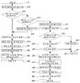
도 2에 도시한 혈액 검사 장치(31)를 이용한 혈액 검사의 플로우를 도 32를 참조해 설명한다.The flow of the blood test using the
우선, 혈액 센서 유닛(44)을 혈액 검사 장치(31)에 장착한다(단계 81). 이 단계 81에서는, 혈액 센서 유닛(44)을 어댑터(40)에 삽입한다. 삽입에 의해 어댑터(40)의 선단이 혈액 센서 유닛(44)의 장착부(41b)에 맞닿는다. 혈액 센서 유닛(44)은 홀더(41)의 탄성으로 어댑터(40)에 걸린다.First, the
다음으로, 혈액 센서(42)의 접속 전극(54a 내지 57a)의 특정을 행한다(단계 82). 여기에서는, 전기 회로부(36)에서 서로 이웃하는 커넥터(61a 내지 61f) 사이의 저항값으로부터 기준 전극(56d)을 특정한다. 그리고, 특정된 기준 전극(56d)으로부터 시계 방향으로 접속 전극(56a), 접속 전극(57a), 접속 전극(54a), 접속 전극(55a)으로 결정한다. 이와 같이, 임의의 각도로 삽입된 혈액 센서 유닛(44)의 혈액 센서(42)의 접속 전극(54a 내지 57a)이 단계 82에서 특정되고, 그 결과, 검출 전극(54 내지 57)이 특정된다.Next, the
다음으로, 혈액 센서 유닛(44)의 선단(41h)을 환자의 피부(13)에 눌러 밀착시킨다(단계 83). 피부(13)의 선단(41h)에의 접촉을, 제1 피부 접촉 센서(62)가 검지하면, 부압 수단(34)의 흡인 펌프(34a)가 동작하여 부압의 발생을 개시한다. 이때, 흡인 펌프(34a)에 인가되는 부하 전류를 제어부(76)에서 검출하여 천자 가능한 부압인지의 여부를 표시부(37)에 표시해도 된다. 부하 전류를 검출하는 대신에, 부압이 발생하고 나서 미리 정해진 시간을 타이머(79)로 계측하여 표시부(37)에 천자가 가능한지의 여부를 표시해도 된다.Next, the
또한, 제2 피부 접촉 센서(150m)가 장착되어 있으면, 부압의 흡인에 의한 피부(13)의 솟아오름을 검지할 수 있다. 그 검지를 표시부(37)에 표시해도 된다.If the second skin contact sensor 150m is attached, the rising of the
이와 같이, 레이저 천자할 경우에 피부(13)에 부압을 인가하면, 이완하고 있던 피부(13)가 긴장 상태가 되므로 천자에 의한 상처가 작아도 혈액(16)을 효율적으로 채취할 수 있다. 따라서, 환자에게 주는 고통이 경감된다. 또한, 부압에 의해 피부(13)를 소정 위치까지 솟아오르게 하여 위치를 규정(규제)하면, 조사하는 레이저광을 정확하게 집광할 수 있다.In this way, when a negative pressure is applied to the
다음으로, 천자 버튼(75)을 압하한다(단계 84). 천자 버튼(75)의 신호는 전기 회로부(36)에서 인식된다. 전기 회로부(36)가 레이저 발사 장치(33)를 구동하면, 레이저가 피부(13)를 향해 발사된다. 레이저로의 천자 전압을 약 300V로 하면, 환자에게 주는 고통은 적어진다.Next, the
다음으로, 채혈을 행한다(단계 85). 레이저에 의한 천자에 의해 환자의 피 부(13)로부터 유출된 혈액(16)을 혈액 센서(42)의 저장부(49)에 저장한다(도 8 등 참조). 저장부(49)에 저장된 혈액(16)은 모세관 현상에 의해 공급로(50)로 유입되어 검출부(51)로 유도된다. 검출부(51)로 유도된 혈액(16)이 검지극으로서의 검출 전극(55)에 도달하면, 측정에 필요한 양의 혈액(16)이 얻어졌다고 판단된다. 이때 부압 수단(34)을 정지해도 되고, 혹은, 피부 접촉 센서(62)가 피부의 비접촉을 검지하고 나서 부압 수단(34)을 정지해도 된다.Next, blood collection is performed (step 85).
한편, 미리 정해진 시간이 경과해도 검출부(51)에서 혈액(16)이 검출되지 않는 경우나 혈액(16)의 양이 적절하지 않은 경우(검출 전극(54)과 검출 전극(55) 사이의 저항으로 검출한다)에는 경보 수단을 작동시켜 경고함과 함께 적절한 처치 내용을 표시부(37)에 표시해도 된다.On the other hand, when the
다음으로, 글루코오스의 측정을 행한다(단계 86). 혈액 중의 글루코오스와 글루코오스 산화 환원 효소를 일정 시간 반응시킨 후, 검출 전극(54)을 작용극으로 하고 검출 전극(56)을 대극으로 하여 두 검출 전극(54, 56)의 사이에 전압을 인가하여 글루코오스 측정을 행하면 된다.Next, glucose is measured (step 86). After reacting glucose in the blood with glucose redox enzyme for a certain time, a voltage is applied between the two
또한, Hct치의 측정을 행한다(단계 87). 검출 전극(57)을 작용극으로 하고 검출 전극(54)을 대극으로 하여 두 검출 전극(54, 57)의 사이에 전압을 인가하면, Hct치에 의존하는 전류가 검출된다. 이 전류에 기초하여 Hct치를 측정할 수 있다.In addition, the Hct value is measured (step 87). When voltage is applied between the two
마지막으로, 혈액 성분의 보정을 행한다(단계 88). 즉, 단계 87에서 검출한 Hct치를 이용하여, 단계 86에서 얻어진 글루코오스량을 보정한다. 보정 후, 그 결과를 표시부(37)에 표시한다. 이상의 단계에 의해 혈당치 측정이 종료되면 사용이 끝난 혈액 센서 유닛(44)은 폐기한다.Finally, the blood component is corrected (step 88). That is, the glucose amount obtained in
측정 단계의Of
도 33은 측정 단계의 플로우차트를 보다 상세하게 모식적으로 설명하는 도면이다.33 is a diagram schematically illustrating the flowchart of the measuring step in more detail.
도 33에 있어서, 단계 151은 혈액 검사 장치(31)의 어댑터(40)에 혈액 센서 유닛(44)을 장착하기 전의 상태를 나타낸다. 단계 152는 가이드부(63)(도 7 참조)를 따라 혈액 센서 유닛(44)을 어댑터(40)에 삽입한 상태를 나타낸다. 단계 153은 커넥터(61)를 압하하여 커넥터(61)가 센서(42)의 접촉 부위(54b 내지 57b, 56c)에 맞닿은 상태를 나타낸다.In FIG. 33,
다음으로, 단계 154로 이행하여, 혈액 검사 장치(31)의 메인 스위치를 기동한다. 그려면, 자동적으로 전기 회로부(36)가 기준 전극(56d)을 검출하여 검출 전극(54 내지 57)을 특정한다. 그 후, 표시부(37)가 측정 준비가 완료된 것을 표시한다.Next, the flow advances to step 154 to start the main switch of the
단계 155에서는, 혈액 검사 장치(31)를 천자하는 피부(13)에 혈액 센서 유닛(44)의 단부를 맞댄다. 도 33에 있어서, 단계 155의 이후에 대해서는 혈액 검사 장치(31)의 장치 본체(39)를 생략하고 혈액 센서 유닛(44)만을 나타낸다. 단계 156에서는 혈액 검사 장치(31)를 환자의 피부(13)에 맞댄다. 피부(13)에 맞닿은 것은 제1 피부 접촉 센서(62)가 검출한다.In
제1 피부 접촉 센서(62)가 피부(13)를 검지하면 단계 157로 이동한다. 그리고, 부압 수단(34)이 동작을 개시하여, 화살표(157a)로 나타내는 바와 같이 부압 실(60)을 흡인한다. 흡인의 결과, 피부(13)가 솟아오른다. 수동식의 부압 수단(140)의 경우는(도 3 참조), 표시부(37)에 수동 개시의 취지의 표시가 이루어져 환자가 수동 펌프 노브(142)의 조작을 개시한다.When the first
부압이 인가되면, 단계 158에 도시하는 바와 같이 피부(13)는 더욱 솟아올라 제2 피부 접촉 센서(피부 접촉 전극)(110m)에 맞닿는다.When a negative pressure is applied, as shown in
제2 피부 접촉 센서(110m)는, 혈액 센서 유닛(44)의 하면에 장착된 혈액 센서(42)의 이면에 형성되거나(도 22 참조), 혈액 센서 유닛(44)의 상면에 혈액 센서(42)가 장착되는 경우에는 장착부(120b)의 하면에 형성된다(도 23 참조).The second
제2 피부 접촉 센서(110m)는 혈액 센서(42)에의 피부(13)의 접촉을 검지할 수 있으면 되기 때문에 전극 대신에 광센서나 기구 스위치, 또는 전기 저항 검출 소자 등을 이용해도 된다.Since the second
단계 159에서는 부압실(60)에서의 피부(13)의 흡인을 정지한다. 한편, 제2 피부 접촉 센서(110m)가 없는 경우는 부압 수단(34)의 동작 개시로부터 미리 정해진 시간의 경과 후에 흡인을 정지하면 된다. 경과 시간은 전기 회로부(36)의 타이머(79)로 계측하면 된다.In
다음으로, 단계 160으로 이동하여, 피부(13)에 레이저광을 조사해 천자한다. 천자에 의해 피부(13)로부터는 혈액(16)이 유출된다. 제2 피부 접촉 센서(110m)가 피부(13)를 검지하면 자동적으로 천자가 행해져도 된다. 또한, 피부(13)의 맞닿음을 표시부(37)에 표시함으로써 환자가 천자 버튼(75)(도 29 참조)을 누르도록 해도 된다. 환자 자신이 천자 버튼(75)을 누르는 경우에는, 환자는 마음의 준비를 할 수 있다.Next, the process proceeds to step 160 where the laser light is irradiated to the
유출된 혈액(16)은, 단계 161에 도시하는 바와 같이, 저장부(49)를 채우고 공급로(50)로 유입된다. 혈액(16)의 유입은 공급로(50)에 의한 모세관 현상과 부압 수단(34)에 의한 공기 구멍(52)으로부터의 흡인에 의해 행해진다.The
단계 162에 도시하는 바와 같이, 혈액(16)은 혈액 센서(42)의 검출부(51)로 유도된다. 혈액(16)의 검출부(51)로의 유입이 검지되면 부압 수단(34)의 동작을 정지한다(단계 163). 혈액(16)이 센서(42)의 검출 전극(55)(도 6 참조)에 도달하면 혈액(16)의 유입이 검지된다. 그리고, 대기 개방 스위치(34c)를 조작해 부압실(60) 내를 외기압으로 한다.As shown in
다음으로, 단계 164에 도시하는 바와 같이, 혈액 검사 장치(31)를 피부(13)에서 뗀다. 측정이 종료하면, 그 취지를 표시부(37)에 표시한다. 그리고, 단계 165로 이동하여 채취한 혈액(16)의 측정 결과를 표시부(37)에 표시한다.Next, as shown in
측정 단계의Of measurement stage플로우Flow 3(인증 단계 있음) 3 (with authentication level)
본 발명의 혈액 검사 장치를 이용하여 혈액 검사를 하는 플로우에는 환자인 사용자를 인증하는 단계가 포함되어도 된다. 레이저 기기이기 때문에 안전성을 고려해 허가된 사람 이외의 사용을 금지하기 위함이다.The blood test using the blood test apparatus of the present invention may include a step of authenticating a user who is a patient. Because it is a laser device, it is forbidden to use other than authorized person in consideration of safety.
도 34에는 인증 단계 261을 포함하는 검사 플로우가 나타난다. 인증은 지문이나 성문, 홍채, 정맥 패턴 등을 이용하여, 환자가 소정의 허가된 사람인지의 여부를 식별해 행하면 된다.34 shows an inspection flow that includes an
사용이 허가된 사람의 경우는 단계 262로 진행한다. 환자는 다이얼을 조작하 여 천자 깊이(레이저 파워)를 설정한다. 그리고, 단계 263으로 이동하여, 혈액 검사 장치(31)의 어댑터(40)에 혈액 센서(42)를 갖는 혈액 센서 유닛(44)을 장착한다. 혈액 센서 유닛(44)의 장착으로 장치 본체(39)의 전원이 자동적으로 기동하여 측정 대기 상태가 된다. 혈액 센서 유닛(44)을 장착하는 단계 263은 단계 261의 앞에 행하여도 무방하다. 혈액 센서 유닛(44)이 장착되어 있지 않으면 측정 동작은 행할 수 없지만 측정 결과의 표시 등은 가능하다.If the person is authorized to use, proceed to step 262. The patient operates the dial to set the puncture depth (laser power). In
다음으로, 단계 264로 진행한다. 단계 264에서는, 혈액 센서 유닛(44)이 피부(13)에 맞닿아 있는지의 여부를 제1 피부 접촉 센서(62)(도 16 등 참조)에서 검지한다. 제1 피부 접촉 센서(62) 대신에, 혈관 유무의 검지, 체온의 검지, 피부의 전기 저항의 검지, 맥동의 검지라도 된다. 어떤 경우라도 안전을 위해 피부(13)에 맞닿은 것을 검지하고 있는 상태에서 단계 265 이후의 동작을 행한다. 피부(13)에 맞닿은 것의 검지가 가능할 때까지 단계 264에서 대기한다.Next, go to
제1 피부 접촉 센서(62)가 피부를 검지하면, 단계 265에서 부압 수단(34)의 동작을 개시한다. 또한, 동시에 레이저 발사 장치(33)의 구동 전압 차지를 개시한다. 그리고, 단계 266으로 진행하여, 부압 수단(34)에 흐르는 전류치를 1 내지 5초간 모니터한다. 전류치에 이상이 있는 경우는, 그 취지를 표시부(37)에 표시하고 단계 264의 앞으로 돌아간다.When the first
전류치가 정상인 경우는 단계 267로 진행하여 부압이 적정한지의 여부를 판정한다. 부압의 적부의 판정은 부압 수단(34)에 흐르는 전류를 미리 정해진 문턱값과 비교함으로써 행한다. 일정한 부압력이 되면 단계 268로 진행하여 레이저광의 발사를 허가한다. 부압이 문턱값을 넘지 않는 경우는 공기 누설(혈액 센서 유닛(44)과 피부(13)의 맞닿음 불량)로서, 부압 수단(34)에 의한 흡인을 정지하고 재시도를 지시함과 함께 단계 264의 앞으로 돌아간다.If the current value is normal, the flow advances to step 267 to determine whether or not the negative pressure is appropriate. The determination of appropriateness of the negative pressure is performed by comparing the current flowing through the negative pressure means 34 with a predetermined threshold value. If the constant negative pressure is reached, the flow proceeds to step 268 to permit firing of the laser light. If the negative pressure does not exceed the threshold, as air leakage (poor contact between the
또한, 제2 피부 접촉 센서(110m)(도 22 참조)를 배치하면, 부압에 의해 흡인된 피부(13)의 솟아오름을 검지할 수 있다. 적절히 피부(13)가 솟아올라 혈액 센서(42)에 밀착하면 레이저광의 발사를 허가한다.Moreover, when the 2nd
단계 268에서는, 레이저광을 발사하여 피부(13)를 천자한다. 그리고, 단계 269로 진행하여 천자에 의해 피부(13)로부터 유출된 혈액(16)을 혈액 센서(42)로 받아들인다. 이때, 부압 수단(34)은 구동을 속행한다.In
다음으로, 단계 270으로 진행하여 혈액(16)이 혈액 센서(42)의 검출부(51)(도 8 참조)에 유입되었는지의 여부를 체크한다. 천자 후의 일정한 경과 시간 내(2 내지 10초의 경우도 있다)에 검출 전극(55)에 혈액(16)이 도달했는지의 여부를 검지한다. 일정한 경과 시간 내에 혈액(16)이 검지되지 않을 때에는 단계 264의 앞으로 돌아가 다시 천자한다. 따라서, 일단 장착된 혈액 센서(42)를 미사용인 채로 낭비하지 않는다. 게다가, 신속히 재천자할 수 있다.Next, the flow proceeds to step 270 to check whether the
혈액(16)이 검지된 경우는 단계 271로 진행하여 혈당치의 측정을 개시한다. 또한, 단계 271에서, 펌프 밸브 유닛(34b)(도 2 참조)을 제어하여 부압의 외기 개방을 개시한다. 이 시점에서는 아직 부압 수단(34)은 동작하고 있다. 부압 수단(34)이 구동하고 있을 때의 소리나 진동에 의해 환자에 대해 측정중이라는 것을 인식시켜, 환자가 혈액 검사 장치(31)를 피부(13)로부터 떼어내지 않도록 하기 위 함이다. 이와 같은 배려에 의해 혈액 성분의 측정 도중에 혈액 검사 장치(31)에 진동이나 충격이 가해지는 것을 방지해 안정적인 측정을 행할 수 있다. 또한, 부압을 개방한 직후에 환자가 피부(13)로부터 장치를 떼어내 혈액(16)을 비산시켜 오염되는 것을 방지한다.If the
단계 271에서 측정이 완료하면, 단계 272로 이동하여 측정한 결과를 표시부(37)에 표시한다. 그리고, 단계 273으로 이동하여 부압 수단(34)(특히 흡인 펌프(34a) 및 펌프 밸브 유닛(34b))(도 2 참조)의 구동을 정지한다. 이후, 환자는 혈액 검사 장치(31)를 피부(13)로부터 떼어 놓는다.When the measurement is completed in
다음으로, 단계 274로 이동하여, 환자가 혈액 센서 유닛(44)을 혈액 검사 장치(31)의 장치 본체(39)로부터 제거하여 폐기한다. 그리고, 단계 275로 이동하여, 혈액 센서 유닛(44)의 제거를 검지하여 장치 본체(39)의 전원을 자동 정지한다.Next, moving to step 274, the patient removes the
이상 설명한 바와 같이, 혈액 검사 장치(31)를 이용한 혈당치의 측정에 있어서, 혈액 검사 장치(31)가 피부(13)에 맞닿아 있는 것을 조건(논리적 조건)으로 레이저 발사 장치(33)를 구동하고 있으므로 피부(13)에의 천자 이외에 레이저광이 방사되는 일이 없어 안전하다.As described above, in the measurement of the blood glucose level using the
또한, 혈액 검사 장치(31)의 사용에 앞서, 단계 261에서 사용자 인증을 행하고 있으므로 허가된 사람만이 조작할 수 있고 무허가의 사람은 조작할 수 없기 때문에 안전하다.In addition, prior to the use of the
혈액 검사 장치(31)의 전원은 자동적으로 기동 및 정지되므로 조작이 쉬워지고, 전지(35) 소비가 억제된다.Since the power supply of the
레이저 조사에서의Laser irradiation부압의Negative pressure 제어 Control
본 발명의 혈액 검사 장치(31)는 천자 후에, 부압을 복수 회 단속하여 인가하여도 무방하다. 도 35 및 도 36을 참조하여, 부압을 인가하는 타이밍과 그 작용을 설명한다.The
제1 피부 접촉 센서(62)가 피부(13)를 검지하면, 시간 166a에서 부압 수단(34)이 구동을 개시한다(도 33의 단계 156에 대응). 부압실(60) 내에 부압이 인가되어 피부(13)는 상태 167a과 같이 긴장하여 솟아오른다(도 33의 단계 157에 대응). 피부(13)가 솟아올라 시간 166b에서 제2 피부 접촉 센서(110m)에 맞닿는다(도 33의 단계 158에 대응). 시간 166b에서 피부(13)는 도 33에 도시하는 상태 167b가 된다. 여기에서, 부압실(60)에 공급하는 부압을 정지한다(도 33의 단계 159에 대응). 그리고, 시간 166c에서 피부(13)를 천자한다(도 33의 단계 160에 대응). 여기에서, 피부(13)는 상태 167c가 되어 혈액(16)이 배어나온다.When the first
그리고, 일단 부압의 공급을 정지한 후, 시간 166d의 시점에서 다시 부압을 인가한다. 부압에 의해, 상태 167d와 같이 피부(13)의 개구부가 넓어져 혈액(16)이 유출되기 쉬워진다(도 33의 단계 161에 대응).After the supply of the negative pressure is stopped once, the negative pressure is applied again at the
이와 같이, 부압을 단속적으로 인가하는 이유의 하나는 피부(13)의 천자공을 넓혀 혈액(16)의 채취를 용이하게 하기 위함이다. 다른 이유는 강한 부압으로 단번에 흡인하면 혈액(16)이 너무 세게 유출되어 과잉 채혈되는 경우가 있으므로 이를 방지하기 위함이기도 하다. 그 때문에, 여분의 혈액(16)이 넘쳐 나오지 않을 정도로 부압 수단(34)을 단속적으로 동작시키고 있다. 이와 같이 하여, 흡인력을 약하 게 해 전력 절약을 도모함과 함께 적당량의 혈액(16)을 채취한다. 적당량의 혈액(16)을 얻어 정밀한 측정이 종료한 단계에서, 혈액 검사 장치(31)를 피부(13)로부터 제거한다(도 33의 단계 164에 대응). 측정이 종료한 시간 166e에 있어서, 피부(13)는, 상태 169e에 도시하는 바와 같이, 부압으로 넓어진 상처(168)를 원래 대로 막는다. 따라서, 상처의 회복이 빨라진다.As described above, one reason for applying the negative pressure intermittently is to widen the puncture hole of the
환자에 따라서는, 레이저 천자하여도 피부(13)로부터 혈액(16)이 유출하기 어려운 경우도 있다. 그러한 경우는, 천자 전의 부압력에 비해 천자 후의 부압력을 크게 하여 혈액(16)이 유출되기 쉽게 해도 된다. 부압력의 제어는 최고 도달압(부압)이 일정하므로 밸브(34b)의 폐쇄 시간을 제어함으로써 행한다. 또한, 단속적인 부압의 구동을 행하지 않아도 계속하여 부압을 인가하도록 구성해도 된다.Depending on the patient,
또한, 본 발명의 혈액 검사 장치(31)는, 천자의 전후에, 이른바 "안마 동작"을 행해도 된다. 도 37을 참조하여, 안마 동작을 설명한다.In addition, the
안마 동작은, 예를 들면, 펌프(예를 들면, 전동식 흡인 펌프)(34a)를 정전압 구동하면서, 밸브(예를 들면, 전자 밸브)(34b)를 소정의 타이밍으로 개폐함으로써 행한다. 도 37에 나타내는 동작예에서는, 제1 피부 접촉 센서(62)가 피부(13)를 검지해 부압 수단(34)이 구동을 개시하고 나서(흡인 개시) 레이저에 의한 천자가 행해질 때까지(기간 92)는 천자 전의 준비로서 주물러 부드럽게 하고(천자 전 준비(주물러 풀기)), 레이저에 의한 천자가 행해진 다음에는, 혈액(16)이 혈액 센서(42)의 검출부(51)로 유입된 것을 검지하여(점착 검지), 전자 밸브(34b)를 폐쇄할 때까지 사이에 적어도 1회의 안마를 행한다. 도 37에 있어서, 공기압의 레벨 90 은 체감으로 흡인을 거의 느끼지 않는 부압 레벨이고(예를 들면, -10kPa), 레벨 91은 펌프(34a)를 정전압 구동했을 경우의 최고 도달압(부압)(예를 들면, -70kPa)이다. 안마 동작을 일으키는 밸브(전자 밸브)(34b)의 개폐 동작은 부압실(60) 내의 공기압이 레벨 90과 레벨 91의 사이에서 변화하고, 또한, 그 변화의 주기가 피부(13)가 부압의 변화에 반응하는 최소 시간보다 긴 시간(예를 들면, 0.1초 이상)이 되도록 하는 타이밍으로 행한다. 이와 같은 밸브(전자 밸브)(34b)의 개폐 동작은 흡인 개시부터 점착 검지·전자 밸브 폐쇄까지의 기간(전자 밸브 폐쇄 동작 기간 94) 동안에 행해진다. 점착 검지 후에 전자 밸브를 폐쇄하는 것은, 전술한 바와 같이, 피부(13)의 천자공을 넓혀 혈액(16)의 채취를 용이하게 하기 위함이다. 혈액(16)의 채취가 이루어져 측정이 종료하면, 부압 수단(34)의 구동을 정지한다(펌프 흡인 정지 및 밸브 개방).The massage operation is performed by opening and closing the valve (for example, the solenoid valve) 34b at a predetermined timing while driving the pump (for example, the electric suction pump) 34a by constant voltage. In the operation example shown in FIG. 37, the first
이와 같은 안마 동작을 행함으로써, 혈관의 혈행이 좋아져 혈액(16)이 유출되기 쉽다. 즉, 피부(13)를 주무름으로써 피천자부가 가열되어(혈행이 좋아짐), 주무르지 않는 경우에 비해 채혈량을 많게 할 수 있다. 또한, 안마 동작은 천자 시의 통증의 경감에도 연결된다.By performing such a massage operation, blood circulation of a blood vessel improves and
레이저 천공 장치에 대해About laser drilling device
본 발명의 혈액 검사 장치(31, 31a)는 도 38에 도시하는 레이저 천공 장치를 포함한다. 이 레이저 천공 장치는 혈액 검사 장치(31, 31a)로부터 혈액 센서 유닛(44), 및 이 혈액 센서 유닛(44)에 관계하는 부재(예를 들면, 혈액 센서(42)와 접속하는 커넥터 등)를 제거한 구조를 갖는다. 이 레이저 천공 장치는 1회의 천자 동작에서 동일한 천자 위치를 "분할 천자"하도록 레이저 발사 장치(33)의 레이저 출력을 제어하는 기능을 갖는다. 여기에서, "분할 천자"란 1회의 천자 동작을 공간적 또는 시간적으로 분할하여 행하는 것을 말한다. 구체적으로는, 전자는 레이저광을 복수의 광로로 분할하여 천자 동작을 행하는 경우(레이저 출력의 분기 제어)이며, 후자는 레이저광을 복수 회로 분할하여 천자 동작을 행하는 경우(레이저 출력의 펄스 제어)이다.The
레이저 조사에서의 레이저광의 분기Branch of laser light in laser irradiation
본 발명의 혈액 검사 장치(31, 31a)는 레이저 발사 장치(33)로부터 발사된 하나의 레이저광을 복수 개로 분기시켜 피부(13)를 천자해도 무방하다. 도 39에 있어서, 참조 부호 "33"은 레이저 발사 장치, "13"은 환자의 피부이다. 또한, 참조 부호 "170a", "170b", "170c"는 각각 입사광에 대해 절반의 빛을 통과시킴과 동시에 나머지 반의 빛을 반사시켜 입사광을 균등하게 분배하는 스플리터이다. 이 스플리터(170a, 170b, 170c)는 하프 미러로 형성된다.The
참조 부호 "171a", "171b", "171c"는 각각 입사한 빛을 전반사시키는 전반사 미러이다. 이 전반사 미러(이하 단순히 "미러"라고 함)(171a, 171b, 171c)는 스플리터(170a, 170b, 170c)와 각각 세트를 이루고 있다. 도 39에서, 이들 스플리터(170a, 170b, 170c) 및 미러(171a, 171b, 171c)는 동일한 조사 위치(177)를 천자하도록 입사광에 대해 소정의 각도로 설정된다.
레이저 발사 장치(33)로부터 출사된 레이저광(172)은 스플리터(170a)에서 레이저광(173a)과 레이저광(173b)으로 분기된다. 분기된 레이저광(173b)은 미 러(171a)에 입사하고, 이 미러(171a)에서 전반사하여 레이저광(174)이 된다. 이 레이저광(174)은 스플리터(170b)에서 레이저광(175a)과 레이저광(175b)으로 분기된다. 분기된 레이저광(175a)은 직접 피부(13)의 조사 위치(177)를 천자한다. 또한, 스플리터(170b)에서 분기된 레이저광(175b)은 미러(171b)에서 전반사하여 레이저광(175c)이 되어 피부(13)의 조사 위치(177)를 천자한다.The
한편, 스플리터(170a)를 통과한 레이저광(173a)은 스플리터(170c)에서 레이저광(176a)과 레이저광(176b)으로 분기된다. 분기된 레이저광(176a)은 직접 피부(13)의 조사 위치(177)를 천자한다. 또한, 스플리터(170c)에서 분기된 레이저광(176b)은 미러(171c)에서 전반사하여 레이저광(176c)이 되어 피부(13)의 조사 위치(177)를 천자한다.On the other hand, the
이와 같이 하나의 레이저광(172)을 복수의 광로로 분기하여 피부(13)의 조사 위치(177)를 천자하므로 출력이 작은 레이저광으로 천자하게 되어 통증을 경감시킬 수 있다. 따라서, 피부(13) 내부의 모세혈관에 레이저광을 집약하여 천자하는 것이 가능해진다.As described above, since one
또한, 도 40에 도시하는 바와 같이, 미러(171c)를 도 39에 도시하는 위치보다 멀리 배치한 경우에는, 스플리터(170c)에서 분기된 레이저광(176b)이 미러(171c)에서 전반사하여 레이저광(176c)이 되어 피부(13)의 조사 위치(177)에 도달할 때까지의 시간이 길어진다. 이와 같이 미러를 적정한 위치에 배치함으로써 분기된 복수의 레이저광을 동일한 조사 위치에 차례로 조사할 수 있도록 레이저 출력을 제어할 수 있다.As shown in FIG. 40, when the
스플리터(170a, 170b, 170c)나 미러(171a, 171b, 171c)는, 도 41에 도시하는 바와 같이, 직육면체를 대각선(178a)으로 2 분할한 큐브 형상의 광학 소자(178)를 이용하는 것이 바람직하다. 큐브 형상의 스플리터(170a, 170b, 170c)는 이음면에 굴절률이 상이한 미러를 접합한 것이며, 큐프 형상의 미러(171a, 171b, 171c)는 전반사하는 면과 전투과하는 면을 접합한 것이다. 이와 같이, 큐브 형상으로 형성된 광학 소자(178)는 투과 광로의 차이나 고스트(ghost)의 발생이 없기 때문에 광로의 분할이나 굴절 등의 변경에 대해 정밀도를 높게 유지할 수 있다. 한편, 스플리터(170a, 170b, 170c)나 미러(171a, 171b, 171c)를 모두 또는 일부씩 하나의 큐브 형상 광학 소자로 구성하는 것도 가능하다.As the
예를 들면, 도 39나 도 40에 도시하는 레이저 분기를 큐브 형상의 광학 소자로 구성하는 경우를 설명한다. 도 39 및 도 40에서는, 레이저광(172)의 분기를 이차원의 이미지로 표현했지만, 이것을 삼차원의 이미지로 표현하면, 도 42의 (a)에 도시하는 바와 같다. 도 42의 (a)에 도시하는 바와 같이, 레이저 발사 장치(33)로부터 출사된 레이저광(172)은 일단 복수의 광로로 분기되어 마지막에는 한 부분의 조사 위치(177)에 집광된다. 도 42의 (b)는 이 분기를 실현하는 큐브의 일례를 도시하고 있다. 도 42의 (b)에 도시하는 큐브(179) 내에는 스플리터(170a, 170b, 170c) 및 미러(171a, 171b, 171c)가 소정의 위치에 각각 고정 배치되어 있다. 이와 같이, 레이저 분기에 사용하는 스플리터(170a, 170b, 170c) 및 미러(171a, 171b, 171c)를 큐브(179) 내에 수납함으로써 세세한 위치 결정이 불필요하게 되어 레이저의 광축 상에 큐브(179)를 배치하는 것만으로 분기 제어된 레이저광을 원하는 위치 에 조사하는 것이 가능하게 된다.For example, the case where the laser branch shown in FIG. 39 or FIG. 40 is comprised from the optical element of cube shape is demonstrated. In FIG. 39 and FIG. 40, although the branch of the
레이저광의 분기 방법은 광섬유를 이용하여 레이저광을 분기해도 된다. 도 63의 (a) 및 도 63의 (b)에 광섬유에 의한 레이저광의 분기 방법을 도시한다. 도 63의 (a)는 레이저 발사 장치(33)로부터 레이저광을 분기 섬유 케이블(421)에 의해 2 분기한 경우이다. 이 경우, 2 분기 섬유 케이블(421)로부터 피부(13)의 동일한 조사 위치(177)를 향해 2 분기된 레이저광(422)이 조사된다. 2 분기 섬유 케이블(421)은 1개의 광섬유 방향성 결합기(423)를 포함한다. 또한, 도 63의 (b)는 레이저 발사 장치(33)로부터 레이저광을 분기 섬유 케이블(424)에 의해 4 분기한 경우이다. 이 경우, 4 분기 섬유 케이블(424)로부터 피부(13)의 동일한 조사 위치(177)를 향해 4 분기된 레이저광(425)이 조사된다. 4 분기 섬유 케이블(424)은 3개의 광섬유 방향성 결합기(423)를 포함한다. 이와 같이, 광섬유를 이용하여도, 도 39에 도시하는 경우와 마찬가지로, 레이저 발사 장치(33)로부터 발사된 하나의 레이저광을 복수 개로 분기시켜 피부(13)를 천자할 수 있다. 특히 섬유 케이블을 사용하는 경우는, 외부에 레이저광이 새지 않기 때문에 스플리터를 사용하는 경우보다 취급이 매우 용이하다.The branching method of a laser beam may branch a laser beam using an optical fiber. 63A and 63B show a branching method of the laser beam by the optical fiber. FIG. 63A illustrates a case where the laser beam is bifurcated by the
도 64는 광섬유 방향성 결합기(423)의 구성을 도시하는 개략도이다. 일반적으로 방향성 결합기는 빛을 분기하는 광학 소자이다. 광섬유 방향성 결합기(423)는 2개의 광섬유(426)의 결합부(427)의 클래드(428)를 제거하여 코어(429)끼리를 근접시킴으로써 구성된다. 광섬유 방향성 결합기(423)에서는, 한쪽의 광섬유(426)로부터 빛이 입사하면, 2개의 코어(429)의 근접 부분에서 빛의 간섭 효과에 의해 다른 쪽의 코어(429)에도 빛이 전파되어 빛을 분기할 수 있다.64 is a schematic diagram showing the configuration of the optical fiber
도 65는 광섬유에 의한 레이저광의 분기 방법으로서, 분기 조인트부(430) 및 섬유 케이블(431)을 사용하는 경우이다. 여기에서는, 레이저 발사 장치(33)로부터 출사된 레이저광(432)은 분기 조인트부(T형 분기)(430)를 경유하여 2 분기된다. 분기 조인트부(430)는, 예를 들면, 삼각형의 전반사 미러(433)를 내장하고 있어 역T자로 레이저광(432)을 분기한다. 분기된 레이저광은 각각 섬유 케이블(431)을 경유하여 피부(13)의 동일한 조사 위치(177)를 천자한다.Fig. 65 shows a case where a branch
일반적으로, 레이저광이 피부(13)에 조사되면, 조사부는 광 흡수에 의해 급격한 온도 상승을 일으킨다. 이 온도 상승에 의해 혈액(16)이 증발하여 피부(13)를 밀어 올려 벌룬 형상이 된다. 그리고, 더욱 피부(13)를 밀어 올려 피부(13)가 파괴되어 혈액(16)이 유출된다. 혈액(16)이 유출된 후 레이저로 천자된 바닥면은 탄화하여 탄화 냄새가 발생한다. 탄화 냄새는 탈취제로 탈취하면 된다.In general, when laser light is irradiated to the
레이저 발사 장치(33)에 있어서, 레이저는 환자의 피부(13)를 약 0.5㎜ 천자하도록 설계된다.In the
이 경우, 레이저 발사 장치(33)의 레이저의 종류는 Er:YaG 또는 CO2 가스로 하면 되고, 파장 영역은 2.7 내지 3.5㎛ 또는 6.5 내지 10.5㎛로 하면 되고, 펄스폭은 50 내지 400㎲, 바람직하게는 200㎲로 하면 되고, 출력은 300mJ 내지 3000mJ로 하면 된다. 또한, 쇼트 직경은 0.1㎜ 내지 0.5㎜로 하고, 쇼트 깊이는 0.3 내지 0.7㎜로 하면 된다. 또한, 차지 전압은 200 내지 700V의 범위, 바람직하게는 500V 로 한다. 이 고전압은 전지를 이용하여 전하를 콘덴서에 차지(충전)한 후 이 차지된 전하를 단번에 방전함으로써 얻어진다.In this case, the type of laser of the
레이저 조사에서의 조사 각도Irradiation angle at laser irradiation
하나의 레이저광을 피부(13)에 대해 기울기 방향에서 조사하여 피부(13)를 천자해도 된다. 도 43에 있어서, 혈액 센서 유닛(44)의 부압실(60)의 내부는 부압 수단(34)에 의해 부압되어 피부(13)가 솟아올라 있다. 솟아오른 피부(13)의 정점(180)의 접선 방향에 대해 90도 미만의 각도로 레이저광(181)을 조사한다. 이와 같이 접선 방향에 대해 90도 미만의 각도로 레이저광을 조사하면, 수직 방향에서 레이저광을 조사하는 경우에 비해 모세혈관이 망라되어 있는 면에 대해 경사 방향에서 레이저광(181)이 조사된다. 그 때문에, 레이저광(181)의 단위 면적당 조사 강도는 약해지지만, 모세혈관을 손상시킬 확률은 증가한다. 따라서, 혈액 채취 효율이 높아진다. 따라서, 천자 깊이가 얕아도 충분한 혈액(16)을 채취할 수 있게 되어 환자에게 주는 통증이 경감된다.One laser beam may be irradiated to the
또한, 레이저광(181)의 조사형은 원형이 아니라, 도 44에 도시하는 바와 같이 타원형(183) 또는 긴 사각형(184)으로 해도 된다. 조사형을 타원형(183) 또는 긴 사각형(184)으로 하면, 레이저광(181)이 망라하고 있는 모세혈관을 손상시킬 확률이 증가하여 혈액 채취 효율이 높아진다. 따라서, 천자 깊이가 얕아도 충분한 혈액(16)을 채취할 수 있으므로 환자에게 고통을 주는 일이 적다.Note that the irradiation type of the
본 발명의 혈액 검사 장치(31, 31a)에 있어서, 하나의 레이저 발사 장치(33)라도 레이저의 출력 강도를 가변할 수 있다.In the
도 45에 도시하는 바와 같이, 레이저 발사 장치(33)와 피부(13)의 사이에 레이저의 투과광량이 상이한 복수 종의 필터, 예를 들면, 감광(ND: Neutral Density) 필터(191a 내지 191d)가 접착된 플레이트(193)를 마련해도 된다. 플레이트(193)를 레이저광(194)의 조사로에 설치한다. 플레이트(193)를 회전시킴으로써 피부(13)에 조사하는 레이저광(194)의 광량을 제어한다. 레이저의 광량을 제어함으로써 천자 깊이를 제어할 수 있다.As shown in FIG. 45, a plurality of types of filters having different amounts of transmitted light of the laser between the
이에 따라, 종래 레이저 강도를 제어하기 위해 행하였던, 플래시램프의 경우는 인가 전압을 제어하고, 반도체 레이저의 경우는 전류를 제어하는 방법 외에 ND 필터에 의한 레이저 천자의 출력 조정도 가능하다. 따라서, 레이저 출력의 보다 세세한 제어가 가능해진다.Accordingly, in addition to the method of controlling the applied voltage in the case of a flash lamp and the control of the current in the case of a semiconductor laser, which has been conventionally performed to control the laser intensity, the output of the laser puncture by the ND filter can be adjusted. Thus, more precise control of the laser output is possible.
또 다른 용도로는, 레이저의 출력 강도를 플래시램프에의 인가 전압으로 결정하는 경우 전압을 가변으로 하면, 전압치의 안정성이 열화하여 레이저 출력이 변동하는 요인이 된다. 이것을 해결하기 위해 전압을 고정으로 하고 레이저광(194)의 출력이 저하(변화)한 경우에도, 투과광량이 상이한 ND 필터(191a 내지 191d)를 이용함으로써 레이저의 출력을 일정하게 유지할 수 있다. 따라서, 안정된 레이저 출력을 얻을 수 있게 된다.In another application, when the output intensity of the laser is determined as the voltage applied to the flash lamp, if the voltage is made variable, the stability of the voltage value is deteriorated, which causes the laser output to vary. In order to solve this problem, even when the voltage is fixed and the output of the
레이저 조사에서의 펄스 제어(시분할)Pulse control (time division) in laser irradiation
천자 시의 통증을 경감시키기 위해 일정한 깊이까지의 천자를 복수 회로 나누어 행하면 된다. 차지 전압으로서 320V 정도의 큰 펄스를 이용하여 1회에 천자하는 방법에 비해, 도 46에 나타내는 바와 같이, 레이저광을 3회의 펄스 198a, 198b, 198c로 분할하고 각각 210V 정도의 작은 펄스를 이용하여 200㎲ 내지 1msec의 간격(휴지 구간)으로 복수 회 천자한다. 이에 따라, 도 47에 도시하는 바와 같이, 각 펄스 198a, 198b, 198c에 대응하여, 피부(13)를 레벨 199a, 199b, 199c의 3 단계로 나누어 천자할 수 있다. 이 경우, 200㎲ 내지 1msec의 휴지 구간에서 콘덴서를 차지하여 고전압을 얻고 있다.In order to alleviate the pain at the time of puncture, a puncture up to a certain depth may be divided into a plurality of times. As shown in Fig. 46, the laser beam is divided into three
이 천자 방법의 제어에 의하면, 1 펄스로 피부(13)를 천자하는 깊이가 얕기 때문에 통증을 경감하면서 소정의 깊이까지 천자할 수 있다. 한편, 이 경우는 펄스 198a, 198b, 198c의 간격을 200㎲ 내지 1msec로 짧게 하는 것이 중요하며, 혈액(16)이 스며 나오기 전에 다음 천자를 행하는 것이 바람직하다.According to the control of the puncturing method, since the depth of puncturing the
또한, 천자 시의 통증을 경감시키기 위해 일정한 깊이까지의 천자를 복수 회로 나누어 행하는 다른 방법으로서, 레이저광을 연속 가변/분할 조사하는 경우에 대해 설명한다. 본 발명에서 천자하는 대상물이란, 예를 들면, 손가락 바닥의 피부이다. 피부는 표면에서부터 차례로, 각질층을 외부에 갖는 표피와, 통점이나 모세관이 존재하는 진피로 형성된다. 따라서, 최초 또는 수차례의 조사로 표피만을 제거하는 에너지를 가한 다음 작은 에너지로 진피를 천자하면 통증이 경감된다.In addition, as another method of dividing a plurality of punctures up to a constant depth in order to alleviate the pain during puncture, a case of continuously varying / dividing irradiation of a laser beam will be described. The object to be punctured in the present invention is, for example, the skin of the finger bottom. The skin is formed, in turn, from the surface, into the epidermis having the stratum corneum on the outside, and the dermis, where the pain points or capillaries are present. Therefore, pain is alleviated by applying energy to remove only the epidermis with the first or several irradiations and then puncturing the dermis with small energy.
예를 들면, 에르븀을 도핑한 Er:YaG를 재료로 하여, φ2.5㎜, 길이 52㎜의 레이저 로드(레이저 결정)(33d)를 이용하는 경우, 1회로 천자할 때의 플래시램프(여기 광원)(33e)에의 차지 전압은 450V 정도의 큰 펄스를 이용한다. 이때의 동작을 일으키기 위한 회로를 도 48의 (a)에 나타내고, 플래시램프(33e)에의 입력 전류를 도 48의 (b)에 나타내고, 레이저의 출력을 도 48의 (c)에 나타내었다.For example, in the case of using a laser rod (laser crystal) 33d having a diameter of 2.5 mm and a length of 52 mm using Er: YaG doped with erbium, the flash lamp (excited light source) when punctured once The charge voltage to 33e uses a large pulse of about 450V. A circuit for causing the operation at this time is shown in Fig. 48A, the input current to the
도 48의 (a)의 회로도에 있어서, 사이리스터(SCR1)(401)가 온 상태가 되면, 트리거 코일(402)로부터 수 kV의 승압된 전압이 출력되고, 플래시램프(33e)에 충전된 크세논 가스가 이온화되어 전해 콘덴서(403)의 주방전이 시작되어 플래시램프(33e)가 발광한다. 이 플래시램프(33e)의 발광에 의해 레이저 로드(33d)가 여기되어 레이저광이 출사된다. 한편, 참조 부호 "404"는 저항(R1)이다.In the circuit diagram of FIG. 48A, when the
상기의 경우는 1회에 천자하는 경우이다.The above case is a case of puncturing once.
다음으로, 전해 콘덴서 1회분의 충전으로 수차례에 나누어 레이저광을 출사하는 경우에 대해 설명한다. 이때의 회로도, 플래시램프(33e)에의 입력 전류, 및 레이저 출력은 도 49의 (a), 도 49의 (b), 및 도 49의 (c)에 각각 나타내었다.Next, the case where the laser beam is emitted several times by charging for one electrolytic capacitor is described. The circuit diagram at this time, the input current to the
수차례로 나누어 플래시램프(33e)를 발광시키는 경우에는, 도 49의 (a)의 회로도에서, 대전류이고 스위칭 속도가 빠른 트랜지스터(IGBT)(411)에 하이 신호가 입력되면, 트랜지스터(IGBT)(411)가 온이 됨과 동시에 플래시램프(33e)의 음극이 그라운드에 접속되어, 플래시램프(33e)에 전해 콘덴서(412)로부터의 전압이 인가되고, 또한 동시에 트리거 코일(413)로부터 수 kV의 승압된 전압이 출력된다. 이에 따라, 플래시램프(33e)에 충전된 크세논 가스가 이온화하고 전해 콘덴서(412)의 주방전이 시작되어 플래시램프(33e)가 발광한다. 다음으로, 트랜지스터(IGBT)(411)에 로우 신호가 입력되면, 트랜지스터(IGBT)(411)가 오프 상태가 되어 플래시램프(33e)에의 전압 인가는 정지한다. 이에 따라, 플래시램프(33e)의 발광도 정지하여 레이저의 출력도 정지한다. 이 동작을 반복함으로써 레이저의 출력을 수차례로 나누어 행할 수 있다. 여기에서는, 2회로 나눈 경우를 나타내고 있다. 한편, 참조 부호 "414"는 저항(R1)이다.In the case where the
도 49의 (c)로부터도 분명한 바와 같이, 처음은 큰 출력으로 조사하고, 다음에 작은 출력으로 조사할 수 있다. 본 예에서 나타낸 Er:YAG의 레이저 로드(33d)를 사용하는 경우는, 레이저광을 출사하기 위한 플래시램프(33e)의 최저 전압은 370V이므로 2회째의 전압은 370V보다 크게 설정하고, 플래시램프(33e)의 발광 시간을 짧게 하여 전체의 에너지를 작게 할 필요가 있다. 이에 따라, 피부(13)를 레벨 199a, 199b의 2 단계로 나누어 천자할 수 있다(도 47 참조).As is also apparent from (c) of Fig. 49, the first can be irradiated with a large output, and the next can be irradiated with a small output. In the case of using the Er:
이 천자 방법의 제어에 의하면, 우선 피부(13)의 표피를 제거하고 나서 진피를 작은 에너지로 천자하기 때문에 진피의 깊은 곳까지 레이저광이 도달하지 않는다. 따라서, 통증을 경감하면서 소정 깊이까지 천자할 수 있다. 한편, 혈액(16)이 스며나오지 않게 표피를 천자하도록 하고 있다.According to the control of the puncturing method, first, the epidermis of the
전원 제어에 대해About power control
본 발명의 혈액 검사 장치는 전기 소모가 큰 레이저 발사 장치를 탑재하고 있으므로 전원의 관리가 중요하다. 전원으로 전지를 이용하는 휴대 기기인 경우에는 용량에 제한이 있으므로 전원의 관리가 특히 중요하다.Since the blood test apparatus of the present invention is equipped with a laser launching device that consumes a lot of electricity, it is important to manage power. In the case of a portable device using a battery as a power source, the capacity is limited, so the management of the power source is particularly important.
또한, 혈당치의 측정이라는 생명의 안전에 관계되는 장치인 경우에는 전원 중단에 의한 측정 불능을 회피하는 것이 요구되어 최악이라도 혈액 검사(예를 들면 혈당치의 측정)만은 실시할 수 있는 것이 중요하다.In addition, in the case of devices related to the safety of life such as the measurement of blood glucose levels, it is required to avoid the inability to measure by interruption of the power supply, and it is important that only the blood test (for example, the measurement of blood glucose levels) can be performed at worst.
본 발명의 혈액 검사 장치는 장치에 포함되는 레이저 발사 장치를 구동하는 전원과 전기 회로부를 구동하는 전원의 전원 공급을 제어하는 전원 제어 회로를 갖 는 것이 바람직하다. 또한 전원 제어 회로는 레이저 발사 장치를 구동하는 전원과 전기 회로부를 구동하는 전원을 독립적으로 제어하는 것이 바람직하다.Blood test apparatus of the present invention preferably has a power supply control circuit for controlling the power supply of the power source for driving the laser firing apparatus included in the device and the power source for driving the electrical circuit portion. In addition, it is preferable that the power supply control circuit independently control the power supply for driving the laser firing apparatus and the power supply for driving the electric circuit unit.
"독립적으로 제어한다"란, 전원(특히 전지)의 잔량이나 전압에 따라 레이저 발사 장치를 구동하는 전력과 전기 회로부를 구동하는 전력을 공급할지의 여부를 결정하는 것, 및 어느 전원으로부터 공급할지를 결정하는 것 등을 의미한다."Independently controlling" means determining whether to supply the power for driving the laser firing device and the power for driving the electric circuit part according to the remaining amount or voltage of the power supply (particularly the battery), and which power supply to supply. It means to do.
본 발명의 혈액 검사 장치의 전원은 전지 전원을 포함하는 것이 바람직하다. 휴대 기기로서 이용할 수 있기 때문이다. 전지 전원은 하나라도 되고 두 개 이상이라도 된다.It is preferable that the power supply of the blood test apparatus of this invention contains a battery power supply. This is because it can be used as a portable device. The battery power supply may be one or two or more.
전지는, 이차 전지 혹은 일차 전지, 또는 그 양자의 조합이라도 된다. 이차 전지의 예로는, 리튬이온 전지, 리튬폴리머 전지, 니켈수소 전지, 니켈카드뮴 전지 등이 포함된다. 일차 전지의 예에는, 리튬 전지, 망간 전지, 알칼리 전지, 옥시라이드 전지 등이 포함된다.The battery may be a secondary battery, a primary battery, or a combination of both. Examples of secondary batteries include lithium ion batteries, lithium polymer batteries, nickel hydrogen batteries, nickel cadmium batteries and the like. Examples of primary batteries include lithium batteries, manganese batteries, alkali batteries, oxylide batteries and the like.
본 발명의 혈액 검사 장치의 전원은 전지 전원 외에 긴급용 전원의 접속 단자를 갖고 있어도 된다. 전지 전원의 전지가 소비되었을 경우에 다른 전원에 접속하여 혈액 검사 장치를 이용하기 위함이다. 긴급 시의 전원의 예로는, 입수가 용이한 건전지, PC 등에서 이용하는 USB 단자, 연료 전지, 수동 발전기(다이나모) 등이 포함된다. 이들 전원을 용이하게 접속할 수 있다.The power supply of the blood test apparatus of the present invention may have a connection terminal for an emergency power supply in addition to the battery power supply. This is to use a blood test apparatus by connecting to another power supply when the battery of the battery power supply is consumed. Examples of emergency power sources include readily available batteries, USB terminals used in PCs, fuel cells, passive generators (dynamo), and the like. These power sources can be easily connected.
또한 본 발명의 혈액 검사 장치의 전원은 전지 전원 외에 외부 전원을 갖고 있어도 된다. 외부 전원과 접속하고 있는 경우에는 외부 전원이 우선적으로 사용되고, 전지로부터의 전기 출력이 정지되거나 또는 전지에 충전이 행해지는 것이 바람 직하다.In addition, the power supply of the blood test apparatus of the present invention may have an external power source in addition to the battery power supply. When connected to an external power source, the external power source is preferentially used, and it is preferable that the electric output from the battery is stopped or the battery is charged.
혈액 검사 장치는, 전지 전원의 전지의 잔량을 측정하는 전지 잔량 측정 회로를 갖고 있어도 된다. 또한 혈액 검사 장치는, 전지 잔량 측정 회로가 측정한 전지 잔량과 미리 정해진 값(전력량)을 비교하는 비교부를 갖는 것이 바람직하다. 전지의 잔량을 파악하여 레이저 천자 또는 검사가 가능한지의 여부를 판단하기 위함이다.The blood test apparatus may have a battery remaining amount measuring circuit for measuring the remaining amount of a battery of a battery power source. Moreover, it is preferable that a blood test apparatus has a comparison part which compares the battery residual quantity measured by the battery residual quantity measurement circuit with a predetermined value (electric power amount). This is to determine whether the laser puncture or inspection is possible by determining the remaining battery capacity.
전술한 바와 같이, 비교부에는 미리 정해진 전력량이 기억된다. 미리 정해진 제1 전력량은 소정 횟수 분의 검사(레이저 천자와 측정을 포함한다)에 필요한 전력량이다. 이 값을 제1 잔량 문턱값이라고 한다. 전지 잔량이 제1 잔량 문턱값을 밑도는 경우는 사용자에게 전지의 교환을 촉구하는 경고(전지 잔량 경고)를 하는 것이 바람직하다. 제1 잔량 문턱값은 설계된 회로에 의해 적절하게 설정되면 되고, 기본적으로는 고정치로 하면 된다.As described above, the predetermined amount of power is stored in the comparator. The first predetermined amount of power is the amount of power required for a predetermined number of inspections (including laser puncture and measurement). This value is called a first residual amount threshold. When the remaining battery level is lower than the first remaining battery threshold value, it is preferable to give a warning (battery remaining warning) to prompt the user to replace the battery. What is necessary is just to set a 1st residual amount threshold value suitably by the designed circuit, and just to set it as a fixed value basically.
미리 정해진 제2 전력량은 1회의 검사(천자 및 측정 등을 포함한다)에 필요한 전력량이다. 이 값을 제2 잔량 문턱값이라고 한다. 전지 잔량이 제2 잔량 문턱값 이상이면, 적어도 1회의 검사가 가능하다고 판단되어 검사가 실시된다. 단, 전술한 바와 같이, 전지 잔량이 제1 잔량 문턱값을 밑돌고 있는 경우에는 전지 잔량 경고를 행하는 것이 바람직하다.The second predetermined amount of power is the amount of power required for one inspection (including puncture and measurement). This value is called the second residual amount threshold. If the remaining battery level is equal to or greater than the second remaining battery threshold value, it is determined that at least one inspection is possible and the inspection is performed. However, as described above, when the remaining battery level is lower than the first remaining amount threshold value, it is preferable to perform a battery remaining warning.
한편, 측정한 전지 잔량이 제2 잔량 문턱값 미만이면, 통상의 검사를 행할 수 없기 때문에 레이저에 의한 천자를 금지하고 검사가 불가능하다는 것을 사용자에게 알리는 것이 바람직하다(사용 불가 표시). 그러나, 레이저에 의한 천자는 불 가능하더라도 전력 소비가 작은 측정 프로세스의 실시는 가능한 경우가 있다. 따라서, 레이저 이외의 수단으로 천자한 다음, 측정을 실시할 수 있다.On the other hand, if the measured battery remaining amount is less than the second remaining amount threshold value, since normal inspection cannot be performed, it is preferable to prohibit puncture by a laser and to inform the user that the inspection is impossible (unusable display). However, even if the puncturing by the laser is impossible, it may be possible to implement a measurement process with low power consumption. Therefore, the measurement can be performed after puncturing by means other than laser.
제2 잔량 문턱값은 전회의 검사에서 소비된 전지의 소비량을 기준으로 설정되는 것이 바람직하다. 구체적으로, 제2 잔량 문턱값은 당해 소비량과 측정을 위한 전기 회로를 구동하기 위한 전력량의 합인 것이 바람직하다. 레이저 발사 장치의 레이저 출력 설정 변경 등에 의해 전지의 소비량이 변화하기 때문에 검사에서 소비되는 전지의 소비량은 최신의 데이터를 기억해 두도록 하고 있다. 이와 같이, 제2 잔량 문턱값은 가변이다.It is preferable that a 2nd residual amount threshold value is set based on the consumption amount of the battery consumed by the last test. Specifically, the second residual amount threshold is preferably the sum of the consumption amount and the amount of power for driving the electric circuit for the measurement. Since the battery consumption varies due to the laser output setting change of the laser launching device, the latest data is stored in the battery consumption consumed in the inspection. As such, the second remaining amount threshold is variable.
미리 정해진 제3 전력량은 레이저 발사 장치에의 1회의 충전에 필요한 전력량과 측정을 위한 전기 회로를 구동하기 위한 전력량의 합이다. 이 값을 제3 잔량 문턱값이라고 한다. 레이저 발사 장치에 충전하기 위한 전원과 전기 회로를 구동하기 위한 전원이 별도인 경우에, 긴급 시에 전기 회로를 구동하기 위한 전원을 이용하여 레이저 발사 장치에 충전할지의 여부를 판단하는 기준으로서 제3 잔량 문턱값을 이용한다. 레이저 발사 장치에의 1회의 충전에 필요한 전력량은 레이저 여기용으로 차지하는 콘덴서의 용량이나 차지 전압이나 차지 전류 및 전지의 내부 저항에 의해 결정된다.The predetermined third amount of power is the sum of the amount of power required for one charge to the laser firing device and the amount of power for driving the electric circuit for the measurement. This value is called a third residual threshold. When the power source for charging the laser launch device and the power source for driving the electric circuit are separate from each other, as a criterion for determining whether to charge the laser launch device by using the power source for driving the electric circuit in an emergency. Use the remaining threshold. The amount of power required for one charge to the laser firing apparatus is determined by the capacity of the capacitor occupied for laser excitation, the charge voltage or the charge current, and the internal resistance of the battery.
전지 잔량에 따른 충전Charge based on battery level전류치의Current 설정 Set
또한, 전지 잔량 측정 회로에서 측정된 전지 잔량에 기초하여 레이저 발사 장치에의 충전을 위한 충전량을 설정해도 된다. 도 61a 내지 도 61c에는 전지 잔량에 부합하여 충전량을 설정하는 예를 나타낸다.In addition, you may set the charge amount for charging to a laser firing apparatus based on the battery residual quantity measured by the battery residual amount measurement circuit. 61A to 61C show examples of setting the charge amount in accordance with the battery remaining amount.
도 61a는, 전지 잔량(Y축)의 비율에 따라 단계적으로 충전 전류를 변경하는 방법이다. 예를 들면, 전지 잔량이 75 내지 100%(제1존)이면 충전 전류치를 최대치(100%)로 하고, 전지 잔량이 50 내지 75%(제2존)이면 충전 전류치를 최대치의 50%로 하고, 전지 잔량이 25 내지 50%(제3존)이면 충전 전류를 25%로 한다.61A is a method of changing the charging current step by step in accordance with the ratio of the remaining battery capacity (Y-axis). For example, if the remaining battery amount is 75 to 100% (first zone), the charging current value is the maximum value (100%), and if the remaining battery amount is 50 to 75% (the second zone), the charging current value is 50% of the maximum value. When the remaining battery amount is 25 to 50% (third zone), the charging current is set to 25%.
도 61b는 전지 잔량(Y축)의 비율에 비례하여 연속적으로 충전 전류(X축)를 변경하는 방법이다.61B is a method of continuously changing the charging current (X-axis) in proportion to the ratio of the battery remaining amount (Y-axis).
도 61c는 전지 잔량(Y축) 비율의 변화 곡선을 기준으로 하여 그 곡선과 반대가 되는 가변 커브가 되도록 연속적으로 충전 전류(X축)를 변경하는 방법이다. 도 61c에서는 "Y=X+a(a: 오프셋분)"의 비례 직선과 대조가 되는 커브에 맞추어 제어한다.61C is a method of continuously changing the charging current (X-axis) so as to be a variable curve opposite to the curve on the basis of the change curve of the remaining battery capacity (Y-axis) ratio. In Fig. 61C, the control is performed in accordance with the curve contrasted with the proportional straight line of "Y = X + a (a: offset amount)".
본 발명의 혈액 검사 장치는 전지 전원의 전지의 전압을 측정하는 전지 전압 측정 회로를 갖는 것이 바람직하다. 또한 혈액 검사 장치는 전지 전압 측정 회로가 측정한 전지 전압과 미리 정해진 전압치를 비교하는 비교부를 갖는 것이 바람직하다.It is preferable that the blood test apparatus of this invention has a battery voltage measuring circuit which measures the voltage of the battery of a battery power supply. Moreover, it is preferable that a blood test apparatus has a comparison part which compares the battery voltage measured by the battery voltage measuring circuit with a predetermined voltage value.
검사(천자와 측정)를 위해 필요한 전력량이 전지에 남아 있는 경우라도, 레이저 천자를 위해 레이저 발사 장치에 충전을 행하면, 측정을 위한 전기 회로부를 구동하기 위한 전압보다 전지 전압이 저하되는 경우가 있다. 따라서, 측정에 필요한 전지 잔량이 있음에도 불구하고 측정을 실시할 수 없는 경우가 발생할 수 있다. 따라서, 전지 전압 측정 회로에서 전지가 충분한 전압을 출력하고 있는지의 여부를 확인한다.Even when the amount of power required for inspection (puncture and measurement) remains in the battery, when the laser firing apparatus is charged for laser puncture, the battery voltage may be lower than the voltage for driving the electric circuit section for measurement. Therefore, a case may occur in which the measurement cannot be performed despite the remaining battery power required for the measurement. Therefore, the battery voltage measuring circuit checks whether or not the battery is outputting sufficient voltage.
전술한 바와 같이, 비교부에는 미리 정해진 전압치가 기억되어 있다. 미리 정해진 제1 전압치는 측정을 위한 전기 회로부를 구동하기 위한 필요 최저 전압보다 어느 정도 높은 전압치인 것이 바람직하다. 이 전압치를 제1 전압 문턱값이라고 한다. 레이저 발사 장치에의 충전에 의해 전지의 전압이 낮아져도 전지의 전압이 필요 최저 전압을 밑돌지 않도록 제1 전압 문턱값을 설정한다. 충전에 의해 전지의 전압이 어느 정도 낮아지는지는 전지의 성질에 따라 상이하므로 전지의 성질에 따라 적절하게 제1 전압 문턱값을 설정한다.As described above, the predetermined voltage value is stored in the comparator. The first predetermined voltage value is preferably a voltage value that is somewhat higher than the minimum voltage required for driving the electrical circuit portion for the measurement. This voltage value is called a first voltage threshold. The first voltage threshold is set so that the voltage of the battery does not fall below the required minimum voltage even when the voltage of the battery is lowered by the charging to the laser firing apparatus. The degree to which the voltage of the battery is lowered by charging is different depending on the characteristics of the battery, so that the first voltage threshold is appropriately set according to the characteristics of the battery.
레이저 발사 장치에 충전을 행하기 전에 전지 전압 측정 회로가 측정한 전지 전압이 제1 전압 문턱값보다 낮다고 비교부에서 판단된 경우에는, 통상적인 전류보다 낮은 전류로 레이저 발사 장치에 충전하는 것이 바람직하다. 저전류로 충전하면 전지 전압이 저하하기 어려워지기 때문이다.If the comparator determines that the battery voltage measured by the battery voltage measuring circuit is lower than the first voltage threshold before charging the laser firing device, it is preferable to charge the laser firing device with a current lower than a normal current. . This is because when the battery is charged at low current, the battery voltage is less likely to decrease.
도 62는 충전량을 변화시켰을 때의 전지의 전압(Y축)과 전지 잔량(X축)의 관계를 나타내었다. 곡선 410은 충전 전류가 0(부하 없음)일 때, 곡선 420은 충전 전류가 I일 때, 곡선 430은 충전 전류가 I'(>I)일 때의 전지의 전압(Y축)과 전지 잔량(X축)의 관계를 각각 나타낸다. 곡선 410에 대해, 유선 420 및 곡선 430 모두 전지 전압이 낮아진 것을 알 수 있다. 이는 전지 내부의 저항(421 및 431)에 의한다.Fig. 62 shows the relationship between the battery voltage (Y axis) and the battery remaining amount (X axis) when the charge amount was changed.
측정을 위한 전기 회로를 구동하기 위해 필요한 전압 레벨을 440으로 하면, 충전 전류가 I인 경우(곡선 420)는 전지의 잔량이 X2가 될 때까지, 전지는 전기 회로를 구동할 수 있다. 한편, 충전 전류가 I'(>I)인 경우(곡선 430)는 전지의 잔량이 X1이 될 때까지만 전지는 전기 회로를 구동할 수 있다. 이와 같이, 충전 전류를 낮추면 전지 전압의 저하가 억제된다. 전지 전압의 저하가 크면, 450으로 나타내는 바와 같이, 사용할 수 없는 전지 에너지가 증가하기 때문에 바람직하지 않다.If the voltage level required to drive the electrical circuit for measurement is 440, the battery can drive the electrical circuit until the remaining charge of the battery becomes X2 when the charging current is I (curve 420). On the other hand, when the charging current is I '(> I) (curve 430), the battery can drive the electric circuit only until the battery has a residual amount of X1. In this manner, when the charging current is lowered, the drop in battery voltage is suppressed. If the decrease in battery voltage is large, as indicated by 450, unusable battery energy increases, which is not preferable.
비교부에 미리 정해진 제2 전압치는, 제1 전압 문턱값 이상으로 본래는 충분히 여유가 있는 전압치이다. 이 전압치를 제2 전압 문턱값이라고 한다. 예를 들면, 제1 전압 문턱값+0.5 내지 1V 정도이다.The second voltage value predetermined in the comparison section is a voltage value that is sufficiently sufficiently inherently above the first voltage threshold value. This voltage value is called a second voltage threshold. For example, the first voltage threshold is about 0.5 to 1V.
비교부가 레이저 발사 장치에 충전을 행하기 전에 전지 전압 측정 회로가 측정한 전지 전압이 제2 전압 문턱값을 웃돈다고 판단한 경우에는, 레이저 발사 장치에 의해 높은 충전 전류로 충전을 행하는 것이 바람직하다.When the comparator determines that the battery voltage measured by the battery voltage measuring circuit exceeds the second voltage threshold before charging to the laser firing apparatus, it is preferable to charge with a high charging current by the laser firing apparatus.
본 발명의 혈액 검사 장치는 혈액 검사의 검사 결과가 표시되는 표시부(도 1 참조)를 갖는다. 전술한 전지 잔량 경고의 표시나 사용 불가 표시는 표시부에 표시되는 것이 바람직하다.The blood test apparatus of this invention has the display part (refer FIG. 1) in which the test result of a blood test is displayed. It is preferable that the above-mentioned display of the remaining battery warning or the unavailability indication be displayed on the display unit.
전원 제어부의 제1 예First example of the power control unit
도 50은 혈액 검사 장치의 제1 예의 전원 제어부(200-1)를 도시한다.50 shows the power control unit 200-1 of the first example of the blood test apparatus.
도 50에 있어서, 가정용 AC 전원(외부 전원의 예로서 이용하였다)에 접속되는 콘센트(201)는 AC 어댑터(202)에 접속된다. AC 어댑터(202)의 출력은 전원 제어 회로(203)의 일단의 입력에 커넥터를 이용하여 탈착 가능하게 접속할 수 있다.In FIG. 50, an
전지(210)는 전지 잔량 및 전지 전압 측정 회로(212)에 접속된다. 회로(212)의 제1 출력은 전원 제어 회로(203)에 접속되고, 회로(212)의 제2 출력은 비교부(211)에 접속된다.The
긴급용 전원의 접속 단자(204)는 전원 제어 회로(203)에 접속된다.The
전원 제어 회로(203)는 AC 어댑터(202)와 접속되어 있을 때에는 AC 어댑터(202) 전원을 우선적으로 사용하고, 전지(210)를 사용하지 않도록 제어한다. AC 어댑터(202)로부터 출력되는 전압을 검지하여 이 전압이 출력되고 있을 때에는, 전지(35)로부터의 공급을 강제적으로 정지하거나 전지(210)에 충전한다.When the power
전원 제어 회로(203)의 제1 출력은 전기 회로부(36a)에 접속된다. 전원 제어 회로(203)의 제2 출력은 승압 회로(205)의 입력에 접속되고, 승압 회로(205)의 출력은 레이저 발사 장치(33)에 접속된다.The first output of the power
비교부(211)의 제1 출력은 전원 제어 회로(203)에 접속된다. 비교부(211)의 제2 출력은 승압 제어부(208)에 접속되고, 승압 제어부(208)의 출력은 승압 회로(205)에 접속된다. 비교부(211)의 제3 출력은 표시 제어부(209)에 접속되고, 표시 제어부(209)의 출력은 표시부(37)에 접속된다.The first output of the comparing
전기 회로부(36a)의 입력에는 천자 버튼(75)이 접속되고, 천자 버튼(75)의 압하 신호는 전기 회로부(36a)를 통해 승압 제어부(208)의 입력에 접속된다. 승압 제어부(208)의 타단 입력에는 긴급 버튼(207)이 접속된다. 전기 회로부(36a)의 출력은 표시부(37)에 접속된다.The
도 50에 도시한 전원 제어부(200-1)의 동작의 제1 예를 도 51을 참조해 설명한다. 단계 311에서 전원을 기동한다. 단계 312로 이행하여 전지 잔량을 측정한다. 단계 313에서 측정된 전지 잔량을 제1 잔량 문턱값과 비교하고, 단계 314에서 제2 잔량 문턱값과 비교한다. 제1 잔량 문턱값이란 소정의 횟수 분의 검사(레이저 천자와 측정을 포함한다)에 필요한 전력량이고, 제2 잔량 문턱값이란 1회의 검사(천자 및 측정 등을 포함한다)에 필요한 전력량이다.A first example of the operation of the power control unit 200-1 shown in FIG. 50 will be described with reference to FIG. 51. In
단계 313에서 전지 잔량이 제1 잔량 문턱값 이상이라고 판단된 경우에는 단계 318로 이행하여 레이저 발사 장치에 충전을 행한다.If it is determined in
단계 313에서 전지 잔량이 제1 잔량 문턱값 미만이라고 판단된 경우로서, 단계 314에서 제2 잔량 문턱값 이상이라고 판단된 경우에는 단계 315에서 사용자에게 전지의 교환을 촉구하기 위한 전지 잔량 경고 표시를 표시하고 단계 318로 이행하여 레이저 발사 장치에 충전을 행한다.If it is determined in
단계 313에서 전지 잔량이 제1 잔량 문턱값 미만이라고 판단된 경우로서, 단계 314에서 제2 잔량 문턱값 미만이라고 판단된 경우에는, 단계 316에서 사용자에게 통상적인 검사를 행할 수 없다는 것을 알리기 위한 사용 불가 표시를 표시부에 표시하고 단계 317에서 레이저 발사 장치에의 전력의 공급을 금지한다.If it is determined in
단계 318에서 레이저 발사 장치에 소정량의 충전이 이루어지면, 단계 319에서 레이저를 발사하여 피부를 천자한다. 단계 321에서 천자된 피부로부터 유출된 혈액의 성분을 측정하고, 얻어진 측정 결과를 표시하고, 혈액 검사를 완료시킨다.If a predetermined amount of charge is made in the laser firing device in
검사 후, 단계 322에서 전지의 잔량을 측정한다. 단계 323에서, 단계 312에서 측정한 전지 잔량과 단계 322에서 측정한 전지 잔량의 차를 구하여, 금회(今回) 전지 소비량을 구한다. 또한 단계 323에서, 금회 전지 소비량과 측정을 위한 전기 회로부를 구동하기 위한 최저 필요 전력량의 합을 구하여, 제2 잔량 문턱값을 재설정한다. 단계 324에서 전원을 정지한다.After the inspection, the remaining battery level is measured in
도 50에 도시한 전원 제어부(200-1)의 동작의 제2 예를, 도 52를 참조하여 설명한다. 단계 311에서 전원을 기동한다. 단계 331에서 전지의 전압을 측정하고, 단계 332에서 전지의 잔량을 측정한다.A second example of the operation of the power control unit 200-1 shown in FIG. 50 will be described with reference to FIG. 52. In
단계 333에서, 단계 331에서 측정된 전압과 전회의 검사 단계 347(후술함)에서 산출된 전압 강하치의 차이를 구한다. 또한 단계 333에서, 이 차이와 측정을 위한 전기 회로부를 구동하기 위한 필요 최저 전압을 비교한다.In
단계 313에서, 단계 332에서 측정된 전지 잔량과 제1 잔량 문턱값을 비교하고, 단계 314에서, 단계 332에서 측정된 전지 잔량과 제2 잔량 문턱값을 비교한다. 전술한 바와 같이, 제1 잔량 문턱값이란 소정 횟수 분의 검사(레이저 천자와 측정을 포함한다)에 필요한 전력량이고, 제2 잔량 문턱값이란 1회의 검사(천자 및 측정 등을 포함한다)에 필요한 전력량이다.In
단계 333에서 상기 차이가 필요 최저 전압 이상이라고 판단된 경우로서, 단계 313에서 전지 잔량이 제1 잔량 문턱값 이상이라고 판단된 경우에는, 단계 341로 이행하여 통상 전류에 의해 레이저 발사 장치에 충전한다.If it is determined in
단계 333에서 상기 차이가 필요 최저 전압 이상이라고 판단된 경우로서, 단계 313에서 전지 잔량이 제1 잔량 문턱값 미만이라고 판단되고, 단계 314에서 전지 잔량이 제2 잔량 문턱값 이상이라고 판단된 경우에는, 단계 315에서 사용자에게 전지의 교환을 촉구하기 위한 전지 잔량 경고 표시를 표시하고 단계 341로 이행하여 통상 전류에 의해 레이저 발사 장치에 충전한다.If it is determined in
단계 333에서 상기 차이가 필요 최저 전압 이상이라고 판단된 경우로서, 단계 313에서 전지 잔량이 제1 잔량 문턱값 미만이라고 판단되고 단계 314에서 전지 잔량이 제2 잔량 문턱값 미만이라고 판단된 경우에는, 단계 316에서 사용자에게 통상적인 검사를 할 수 없다는 것을 알리기 위한 사용 불능 표시를 표시하고, 또한 단계 317에서 레이저 발사 장치에의 전력의 공급을 금지한다.If it is determined in
한편, 단계 333에서 상기 차이가 필요 최저 전압 미만이라고 판단된 경우에는, 단계 335로 이행하여 레이저 발사 장치에 통상적인 충전을 할 수 없는 것(예를 들면, 충전 시간이 길어지는 것)을 사용자에게 알리기 위한 통상 충전 불능 표시를 표시하고, 단계 336에서 사용자에게 검사를 실시할 경우에는 긴급 버튼을 누르도록 요구한다.On the other hand, if it is determined in
단계 336에서 긴급 버튼이 눌리지 않은 경우에는 단계 317로 이행하여 레이저 발사 장치에의 전력의 공급을 금지한다.If the emergency button is not pressed in
단계 336에서 긴급 버튼이 눌린 경우에는 단계 337에서 평소보다 저전류에 의해 레이저 발사 장치에 충전한다. 충전을 위한 전류치의 제어는 승압 제어부(208)가 행한다. 단계 338에서 레이저 발사 장치가 레이저를 발사하여 피부를 천자하고, 단계 339에서 천자된 피부로부터 유출된 혈액의 성분을 측정하여, 측정 결과를 표시한다. 검사 후에 단계 348에서 전원을 정지한다.If the emergency button is pressed in
한편, 단계 341에서 통상 전류에 의해 레이저 발사 장치에 충전한 경우에는 단계 342에서 충전중의 전지의 전압을 측정한다. 단계 343에서, 충전된 레이저 발사 장치로부터 레이저를 발사하여 피부를 천자한다. 단계 344에서, 천자된 피부로부터 유출된 혈액의 성분을 측정하고 측정 결과를 표시한다. 단계 345에서, 측정 후의 전지 잔량을 측정한다.On the other hand, when the laser firing apparatus is charged with the normal current in
단계 346에서, 단계 332에서 측정한 전지 잔량과 단계 345에서 측정한 전지 잔량의 차이를 구하여 금회 전지 소비량으로 한다. 또한 단계 346에서, 금회 전지 소비량과 측정을 위한 전기 회로부를 구동하기 위한 필요 최저 전력량의 합을 구하여 제2 잔량 문턱값을 재설정한다.In
또한 단계 347에서, 단계 331에서 측정한 전압과 단계 342에서 측정한 전압의 차이를 산출하여 전압 강하치로 한다. 전압 강하치는 다음 검사에서의 단계 333(전술함)에서 이용된다. 그 후, 단계 348에서 전원이 정지한다.In
도 50에 도시한 전원 제어부(200-1)의 동작의 제3 예를 도 53을 참조해 설명한다. 단계 311에서 전원을 기동한다. 단계 312로 이행하여 전지 잔량을 측정한다. 단계 313에서 측정된 전지 잔량과 제1 잔량 문턱값을 비교하고, 단계 314에서 측정된 전지 잔량과 제2 잔량 문턱값을 비교한다.A third example of the operation of the power control unit 200-1 shown in FIG. 50 will be described with reference to FIG. 53. In
전술한 바와 같이, 제1 잔량 문턱값이란 소정 횟수 분의 검사(레이저 천자와 측정을 포함한다)에 필요한 전력량이고, 제2 잔량 문턱값이란 1회의 검사(천자 및 측정 등을 포함한다)에 필요한 전력량이다.As described above, the first residual amount threshold is an amount of power required for a predetermined number of inspections (including laser puncture and measurement), and the second residual amount threshold is required for one inspection (including puncture and measurement, etc.). The amount of power.
단계 313에서 전지 잔량이 제1 잔량 문턱값 이상이라고 판단된 경우에는, 단계 351로 이행하여 전회의 검사에서 레이저 발사 장치에 충전하기 위한 충전 전류치(후술하는 단계 358을 참조)를 금회 검사에서의 충전 전류치로서 설정한다.If it is determined in
단계 313에서 전지 잔량이 제1 잔량 문턱값 미만이라고 판단된 경우로서, 단계 314에서 전지 잔량이 제2 잔량 문턱값 이상이라고 판단된 경우에는, 단계 315에서 사용자에게 전지의 교환을 촉구하기 위한 전지 잔량 경고 표시를 표시하고 단계 351로 이행하여 전회의 검사에서 레이저 발사 장치에 충전하기 위한 충전 전류치(후술하는 단계 358을 참조)를 금회 검사에서의 충전 전류치로서 설정한다.If it is determined in
단계 313에서, 전지 잔량이 제1 잔량 문턱값 미만이라고 판단된 경우로서, 단계 314에서 제2 잔량 문턱값 미만이라고 판단된 경우에는, 단계 316에서 사용자에게 검사를 행할 수 없다는 것을 알리기 위한 사용 불가 표시를 표시하고 단계 317에서 레이저 발사 장치에의 전력의 공급을 금지한다.In
단계 352에서는, 단계 351에서 설정한 충전 전류치에 의해 레이저 발사 장치에의 충전을 행한다. 전지의 교환이나 전원 종류가 바뀐 경우에는 소정의 충전 전류치에 의해 충전을 행한다. 단계 353에서 충전중의 전지의 전압을 측정한다. 단계 354에서 충전중의 전지의 전압과 제1 전압 문턱값을 비교한다. 단계 356에서 충전중의 전지의 전압과 제2 전압 문턱값을 비교한다.In
전술한 바와 같이, 제1 전압 문턱값은 측정을 위한 전기 회로부를 구동하기 위한 필요 최저 전압보다 어느 정도 높은 전압치이며, 제2 전압 문턱값은 제1 전압 문턱값 이상으로 본래는 충분히 여유가 있는 전압치이다. 이 전압치를 제2 전압 문턱값이라고 한다. 예를 들면, 제1 전압 문턱값+0.5 내지 1V 정도이다.As mentioned above, the first voltage threshold is a voltage value that is somewhat higher than the minimum voltage required to drive the electrical circuit part for measurement, and the second voltage threshold is inherently sufficient above the first voltage threshold. Voltage value. This voltage value is called a second voltage threshold. For example, the first voltage threshold is about 0.5 to 1V.
단계 354에서 충전중의 전지의 전압이 제1 전압 문턱값 이상이라고 판단되고 단계 356에서 제2 전압 문턱값 이하라고 판단된 경우에는, 단계 358에서 그 때의 충전 전류치를 다음 검사를 위한 충전 전류치로서 기억한다(다음 검사에서의 단계 351에서 이용한다).If it is determined in
단계 354에서 충전중의 전지의 전압이 제1 전압 문턱값 미만이라고 판단된 경우에는 단계 355에서 충전 전류치를 저하시킨다. 한편 단계 356에서, 충전중의 전지의 전압이 제2 전압 문턱값을 넘고 있다고 판단된 경우에는 단계 357에서 충전 전류를 높인다.If it is determined in
단계 359에서 레이저 발사 장치로부터 레이저를 발사하여 피부를 천자한다. 단계 361에서 천자된 피부로부터 유출된 혈액의 성분을 측정하고 측정 결과를 표시한다. 단계 362에서 검사 종료 후의 전지 잔량을 측정한다. 단계 363에서, 단계 312에서 측정한 잔량과 단계 362에서 측정한 잔량의 차이를 구하여 금회 전지 소비량으로 한다. 또한 단계 363에서, 금회 전지 소비량과 측정을 위한 전기 회로부를 구동하기 위한 필요 최저 전력량의 합을 제2 잔량 문턱값으로서 재설정한다. 단계 364에서 전원을 정지한다.In step 359, the laser is fired from the laser firing device to puncture the skin. In
도 50에 도시한 전원 제어부(200-1)의 동작의 제4 예를 도 54를 참조해 설명한다. 도 54에 나타낸 플로우는 도 53에 나타낸 플로우와 유사하지만, 레이저 발사 장치에의 충전을 위한 충전 전류치의 설정 방법이 상이하다. 즉, 도 54에 나타낸 플로우에서는 단계 350에서 전지의 잔량에 기초하여 충전 전류치를 설정한다. 구체적인 설정 방법은 전술한 대로이지만, 기본적으로, 전지 잔량의 비율이 높을수록 높은 전류치로 충전한다.A fourth example of the operation of the power control unit 200-1 shown in FIG. 50 will be described with reference to FIG. 54. The flow shown in FIG. 54 is similar to the flow shown in FIG. 53, but the method of setting the charge current value for charging to the laser firing apparatus is different. That is, in the flow shown in FIG. 54, the charging current value is set in
그 외의 단계는 도 53에 나타낸 플로우와 마찬가지이다.Other steps are the same as those shown in FIG.
전원 제어부의 제2 예를 설명한다.A second example of the power control unit will be described.
도 55는 혈액 검사 장치의 제2 예의 전원 제어부(200-2)를 도시한다.55 shows the power supply control unit 200-2 of the second example of the blood test apparatus.
도 55에 있어서, 가정용 AC 전원(외부 전원의 예로서 이용하였다)에 접속되 는 콘센트(201)는 AC 어댑터(202)에 접속된다. AC 어댑터(202)의 출력은 전원 제어 회로(203)의 일단의 입력에 커넥터를 이용하여 탈착 가능하게 접속할 수 있다.In FIG. 55, an
전지(210a)는 전지 잔량 및 전지 전압 측정 회로(212)에 접속된다. 회로(212)의 제1 출력은 전원 제어 회로(203)에 접속되고, 회로(212)의 제2 출력은 비교부(211)에 접속된다. 전지(210b)는 전기 회로부(36a)에 접속된다. 긴급용 전원의 접속 단자(204)는 전원 제어 회로(203)에 접속된다.The
전원 제어 회로(203)는 AC 어댑터(202)와 접속되고 있을 때에는 AC 어댑터(202) 전원을 우선적으로 사용하고, 전지(210a)를 사용하지 않도록 제어한다. AC 어댑터(202)로부터 출력되는 전압을 검지하여 이 전압이 출력되고 있을 때에는, 전지(35)로부터의 공급을 강제적으로 정지하거나 전지(210a)에 충전한다.When the power
전원 제어 회로(203)의 출력은 승압 회로(205)에 접속되고, 승압 회로(205)의 출력은 레이저 발사 장치(33)에 접속된다.The output of the power
비교부(211)의 제1 동력은 전원 제어 회로(203)에 접속된다. 비교부(211)의 제2 출력은 승압 제어부(208)에 접속되고, 승압 제어부(208)의 출력은 승압 회로(205)에 접속된다. 비교부(211)의 제3 출력은 표시 제어부(209)에 접속되고, 표시 제어부(209)의 출력은 표시부(37)에 접속된다.The first power of the
전기 회로부(36a)의 입력에는 천자 버튼(75)이 접속되고, 천자 버튼(75)의 압하 신호는 전기 회로부(36a)를 통해 승압 제어부(208)의 입력에 접속된다. 승압 제어부(208)의 타단의 입력에는 긴급 버튼(207)이 접속된다. 전기 회로부(36a)의 타단의 출력은 표시부(37)에 접속된다.The
도 55에 도시한 전원 제어부(200-2)의 동작의 제1 예를 도 56을 참조해 설명한다. 도 56에 나타낸 플로우는 도 51에 나타낸 플로우와 유사하다. 단, 전원 제어부(200-2)는 2개의 전지(210a 및 210b)를 갖고, 전지(210a)(레이저용 전지)만이 레이저 발사 장치의 충전에 이용된다. 따라서, 단계 312'에서 레이저용 전지의 전지 잔량을 측정하고, 단계 313'에서 단계 312'에서 측정된 잔량과 제1 잔량 문턱값을 비교하고, 단계 314'에서 단계 312'에서 측정된 잔량과 제2 잔량 문턱값을 비교한다.A first example of the operation of the power control unit 200-2 shown in FIG. 55 will be described with reference to FIG. 56. The flow shown in FIG. 56 is similar to the flow shown in FIG. 51. However, the power supply control unit 200-2 has two
그 외의 단계는 도 51에 나타낸 플로우의 단계와 마찬가지이다.Other steps are the same as those in the flow shown in FIG.
도 55에 도시한 전원 제어부(200-2)의 동작의 제2 예를 도 57을 참조해 설명한다. 도 57에 나타낸 플로우는 도 56에 나타낸 플로우와 유사하지만, 레이저 발사 장치에의 충전을 위한 충전 전류치의 설정 방법이 상이하다. 즉, 도 57에 나타낸 플로우에서는 단계 350에서 충전 전류치의 설정을 전지의 잔량에 기초하여 행한다. 구체적인 설정 방법은 전술한 대로이지만, 기본적으로는, 전지 잔량의 비율이 높을수록 높은 전류치로 충전한다.A second example of the operation of the power control unit 200-2 shown in FIG. 55 will be described with reference to FIG. 57. The flow shown in FIG. 57 is similar to the flow shown in FIG. 56, but the method of setting the charge current value for charging to the laser firing apparatus is different. That is, in the flow shown in FIG. 57, the charging current value is set in
그 외의 단계는 도 56에 나타낸 플로우와 마찬가지이다.Other steps are the same as those shown in FIG.
전원 제어부의 제3 예를 설명한다.A third example of the power control unit will be described.
도 58은 혈액 검사 장치의 제3 예의 전원 제어부(200-3)를 도시한다.58 shows the power control unit 200-3 of the third example of the blood test apparatus.
도 58에 있어서, 가정용 AC 전원(외부 전원의 예로서 이용하였다)에 접속되는 콘센트(201)는 AC 어댑터(202)에 접속된다. AC 어댑터(202)의 출력은, 전원 제어 회로(203)의 일단의 입력에 커넥터를 이용하여 탈착 가능하게 접속할 수 있다.In FIG. 58, an
전지(210a)는 전지 잔량 및 전지 전압 측정 회로(212a)에 접속된다. 회로(212a)의 제1 출력은 전원 제어 회로(203)에 접속되고, 회로(212a)의 제2 출력은 비교부(211)에 접속된다. 전지(210b)는 전지 잔량 및 전지 전압 측정 회로(212b)에 접속된다. 회로(212b)의 제1 출력은 전원 제어 회로(203)에 접속되고, 회로(212b)의 제2 출력은 비교부(211)에 접속된다. 긴급용 전원의 접속 단자(204)는 전원 제어 회로(203)에 접속된다.The
전지(212a)와 전지(212b)는 모두 전원 제어부(203)에 접속되어 있으므로 레이저 발사 장치(33)의 충전 및 전기 회로부(36a)의 구동에 이용된다. 통상적으로, 전지(212a)는 레이저 발사 장치를 충전하고, 전지(212b)는 전기 회로부(36a)를 구동한다. 단, 전지(212a)의 잔량이 부족하여 레이저 발사 장치를 충전할 수 없는 경우로서, 전지(212b)에 충분한 잔량이 있는 경우에는, 긴급 수단으로 전지(212b)가 레이저 발사 장치를 충전한다.Since the
전원 제어 회로(203)는 AC 어댑터(202)와 접속되고 있을 때에는 AC 어댑터(202) 전원을 우선적으로 사용하고, 전지(210a) 및 전지(210b)를 사용하지 않도록 제어한다. AC 어댑터(202)로부터 출력되는 전압을 검지하여 이 전압이 출력되고 있을 때에는 전지(210a) 및 전지(210b)로부터의 공급을 강제적으로 정지하거나 전지(210a) 및 전지(210b)에 충전한다.The power
전원 제어 회로(203)의 제1 출력은 전기 회로부(36a)에 접속된다. 전원 제어 회로(203)의 제2 출력은 승압 회로(205)의 입력에 접속되고, 승압 회로(205)의 출력은 레이저 발사 장치(33)에 접속된다.The first output of the power
비교부(211)의 제1 출력은 전원 제어 회로(203)에 접속된다. 비교부(211)의 제2 출력은 승압 제어부(208)에 접속되고, 승압 제어부(208)의 출력은 승압 회로(205)에 접속된다. 비교부(211)의 제3 출력은 표시 제어부(209)에 접속되고, 표시 제어부(209)의 출력은 표시부(37)에 접속된다.The first output of the comparing
전기 회로부(36a)의 입력에는 천자 버튼(75)이 접속되어 천자 버튼(75)의 압하 신호는 전기 회로부(36a)를 통해 승압 제어부(208)의 입력에 접속된다. 승압 제어부(208)의 타단의 입력에는 긴급 버튼(207)이 접속된다. 전기 회로부(36a)의 출력은 표시부(37)에 접속된다.The
도 58에 도시한 전원 제어부(200-3)의 동작의 제1 예를 도 59를 참조해 설명한다.A first example of the operation of the power control unit 200-3 shown in FIG. 58 will be described with reference to FIG. 59.
도 59에 나타낸 플로우는 도 56에 나타낸 플로우와 유사하다. 단, 전원 제어부(200-3)는 2개의 전지(210a 및 210b)를 갖고, 모든 전지가 전원 제어 회로(203)에 접속되어 있다. 기본적으로, 전지(210a)(레이저용 전지)는 레이저 발사 장치의 충전에 이용되고, 전지(210b)(시스템용 전지)는 전기 회로부(36a)를 구동하기 위해 이용된다. 그러나, 전지(210a)의 잔량이 부족한 경우 등의 긴급 시에는 전지(210b)를 레이저 발사 장치의 충전에 이용하는 경우가 있다.The flow shown in FIG. 59 is similar to the flow shown in FIG. However, the power supply control unit 200-3 has two
도 56에 나타낸 플로우와 마찬가지로, 단계 314'에서 레이저용 전지의 잔량과 제2 잔량 문턱값이 비교되는데, 레이저용 전지의 잔량이 제2 잔량 문턱값 미만이라고 판단되는 경우에는, 단계 371에서, 사용자에게 레이저용 전지를 사용할 수 없다는 것을 알리기 위한 표시를 행한다.In the same manner as the flow shown in FIG. 56, in
단계 372에서 시스템용 전지의 잔량을 측정한다. 단계 373에서, 단계 372에서 측정된 잔량과 제3 잔량 문턱값을 비교한다. 제3 잔량 문턱값이란, 레이저를 발사하기 위해 필요하게 되는 레이저 발사 장치에 충전해야 할 전력량과 시스템 최저 전력량의 합으로 하면 된다.In
단계 373에서 시스템용 전지의 잔량이 제3 잔량 문턱값 미만이라고 판단된 경우에는, 단계 316에서 사용자에게 검사를 행할 수 없다는 것을 알리기 위한 사용 불능 표시를 표시한다. 또한, 단계 317에서 레이저 발사 장치에의 전력의 공급을 금지한다.If it is determined in
한편, 단계 373에서, 시스템용 전지의 잔량이 제3 잔량 문턱값 이상이라고 판단된 경우에는, 단계 374에서 사용자에게 레이저 발사 장치에 통상적인 충전을 할 수 없다는(예를 들면, 평소보다 긴 충전 시간을 필요로 한다) 것을 알리기 위한 통상 충전 불능 표시를 표시하고, 그래도 검사를 실시하고자 하는 경우에는, 긴급 버튼을 누르도록 요구한다.On the other hand, if it is determined in
단계 375에서 긴급 버튼이 눌리지 않은 경우에는, 단계 317로 이행하여 레이저 발사 장치에의 전력의 공급을 금지한다.If the emergency button is not pressed in
한편, 단계 375에서 긴급 버튼이 눌린 경우에는, 단계 376에서 시스템용 전지에 의한 레이저 발사 장치에의 충전을 허가하고, 단계 377에서 레이저 발사 장치의 충전을 행한다. 단계 377에서의 충전은 시스템용 전지의 전압 강하를 피하기 위해 평소보다 저전류로 행하는 것이 바람직하다. 충전을 위한 전류치의 제어는 승압 제어부(208)가 행한다.On the other hand, when the emergency button is pressed in
단계 378에서, 레이저 발사 장치로부터 레이저를 발사하여 피부를 천자한다. 단계 379에서, 천자된 피부에서 유출된 혈액의 성분을 측정하고 측정 결과를 표시한다. 단계 381에서, 사용자에게 시스템용 전지를 교환할 것을 재촉하기 위한 시스템용 전지 교환 경고 표시를 표시한다. 단계 382에서 전원을 정지한다.In
도 58에 도시한 전원 제어부(200-3)의 동작의 제2 예를 도 60을 참조해 설명한다. 도 60에 나타낸 플로우는 도 59에 나타낸 플로우와 유사하지만, 레이저 발사 장치에의 충전을 위한 충전 전류치의 설정 방법이 상이하다. 즉, 도 60에 나타낸 플로우에서, 단계 350에서 전지의 잔량에 기초하여 충전 전류치를 설정한다. 구체적인 설정 방법은 전술한 대로이지만, 기본적으로, 전지 잔량의 비율이 높을수록 높은 전류치로 충전한다.A second example of the operation of the power control unit 200-3 shown in FIG. 58 will be described with reference to FIG. 60. The flow shown in FIG. 60 is similar to the flow shown in FIG. 59, but the method of setting the charge current value for charging to the laser firing apparatus is different. That is, in the flow shown in FIG. 60, the charging current value is set in
그 외의 단계는 도 59에 나타낸 플로우와 마찬가지이다.Other steps are the same as those shown in FIG.
2006년 3월 22일에 출원된 일본 특허출원 2006-078418, 마찬가지로 2006년 3월 22일에 출원된 일본 특허출원 2006-078419, 마찬가지로 2006년 3월 22일에 출원된 일본 특허출원 2006-078420, 마찬가지로 2006년 3월 22일에 출원된 일본 특허출원 2006-078427의 각 일본 출원에 포함되는 명세서, 도면 및 요약서의 개시 내용은 모두 본원에 원용된다.Japanese Patent Application 2006-078418, filed March 22, 2006, Japanese Patent Application 2006-078419, similarly filed March 22, 2006, Japanese Patent Application 2006-078420, filed March 22, 2006, Likewise, the disclosures of the specification, the drawings, and the summary contained in each Japanese application of Japanese Patent Application 2006-078427, filed March 22, 2006 are all incorporated herein.
본 발명의 혈액 검사 장치 및 그 제어 방법은, 간단한 구성으로, 환자에게 부담을 주지 않고 소량으로 측정에 필요 충분한 혈액을 확실히 채취하여, 안정적으로 측정할 수 있는 혈액 검사 장치 및 그 제어 방법으로서 유용하다. 이 때문에, 의료 분야에서의 혈액 검사 장치에 적용할 수 있는 것은 물론, 특히 당뇨병 환자 등이 사용하는 가정용 의료 기구 등에도 널리 적용할 수 있다.The blood test apparatus and control method thereof according to the present invention are useful as a blood test apparatus and control method capable of reliably collecting and stably measuring sufficient blood necessary for measurement in a small amount without burdening the patient with a simple configuration. . For this reason, it is applicable not only to the blood test apparatus in a medical field, but also to the home medical apparatus etc. which are used especially by a diabetic person.
Claims (23)
Translated fromKoreanApplications Claiming Priority (9)
| Application Number | Priority Date | Filing Date | Title |
|---|---|---|---|
| JP2006078427 | 2006-03-22 | ||
| JPJP-P-2006-00078420 | 2006-03-22 | ||
| JP2006078420 | 2006-03-22 | ||
| JP2006078419 | 2006-03-22 | ||
| JPJP-P-2006-00078419 | 2006-03-22 | ||
| JPJP-P-2006-00078418 | 2006-03-22 | ||
| JP2006078418 | 2006-03-22 | ||
| JPJP-P-2006-00078427 | 2006-03-22 | ||
| PCT/JP2007/055919WO2007108518A1 (en) | 2006-03-22 | 2007-03-22 | Blood test apparatus and method of controlling the same |
Publications (2)
| Publication Number | Publication Date |
|---|---|
| KR20080095267A KR20080095267A (en) | 2008-10-28 |
| KR101058728B1true KR101058728B1 (en) | 2011-08-22 |
Family
ID=38522544
Family Applications (1)
| Application Number | Title | Priority Date | Filing Date |
|---|---|---|---|
| KR1020087021076AExpired - Fee RelatedKR101058728B1 (en) | 2006-03-22 | 2007-03-22 | Blood test device and control method thereof |
Country Status (7)
| Country | Link |
|---|---|
| US (2) | US7976478B2 (en) |
| EP (1) | EP1997435A4 (en) |
| JP (1) | JPWO2007108518A1 (en) |
| KR (1) | KR101058728B1 (en) |
| CN (1) | CN101404936B (en) |
| CA (1) | CA2646723A1 (en) |
| WO (1) | WO2007108518A1 (en) |
Families Citing this family (30)
| Publication number | Priority date | Publication date | Assignee | Title |
|---|---|---|---|---|
| US20100210970A1 (en)* | 2007-07-18 | 2010-08-19 | Panasonic Corporation | Piercing device, blood inspection device, and piercing method |
| JP5254233B2 (en)* | 2007-08-07 | 2013-08-07 | パナソニック株式会社 | Puncture device and blood test device |
| JP5205389B2 (en)* | 2007-10-11 | 2013-06-05 | パナソニック株式会社 | High voltage generation circuit, puncture device and blood test device |
| PL2218399T3 (en) | 2009-02-17 | 2014-03-31 | Hoffmann La Roche | Reuse protection for lancet system |
| EP2724739B1 (en) | 2009-07-30 | 2015-07-01 | Tandem Diabetes Care, Inc. | Portable infusion pump system |
| US9357957B2 (en) | 2010-01-21 | 2016-06-07 | Arkray, Inc. | Measuring apparatus, measuring system, electric power supply apparatus, and electric power supply method |
| JP5577506B2 (en) | 2010-09-14 | 2014-08-27 | ソーラテック コーポレイション | Centrifugal pump device |
| KR101185482B1 (en)* | 2011-03-11 | 2012-10-02 | (주)지티씨 | Laser apparatus and laser production method |
| EP2693609B1 (en) | 2011-03-28 | 2017-05-03 | Thoratec Corporation | Rotation and drive device and centrifugal pump device using same |
| US9180242B2 (en) | 2012-05-17 | 2015-11-10 | Tandem Diabetes Care, Inc. | Methods and devices for multiple fluid transfer |
| US9371826B2 (en) | 2013-01-24 | 2016-06-21 | Thoratec Corporation | Impeller position compensation using field oriented control |
| US9173998B2 (en) | 2013-03-14 | 2015-11-03 | Tandem Diabetes Care, Inc. | System and method for detecting occlusions in an infusion pump |
| US10052420B2 (en) | 2013-04-30 | 2018-08-21 | Tc1 Llc | Heart beat identification and pump speed synchronization |
| USD746976S1 (en)* | 2013-09-08 | 2016-01-05 | Theranos, Inc. | Blood collection device |
| USD745662S1 (en)* | 2013-09-08 | 2015-12-15 | Theranos, Inc. | Blood collection device |
| EP3082574B1 (en)* | 2013-12-16 | 2023-07-12 | Dexcom, Inc. | Systems and methods for monitoring and managing life of a battery in an analyte sensor system worn by a user |
| WO2015100109A1 (en)* | 2013-12-27 | 2015-07-02 | Abbott Diabetes Care Inc. | Systems, devices, and methods for authentication in an analyte monitoring environment |
| US20160058930A1 (en)* | 2014-08-26 | 2016-03-03 | Thoratec Corporation | Blood pump and method of suction detection |
| EP3256183B1 (en) | 2015-02-11 | 2025-08-13 | Tc1 Llc | Heart beat identification and pump speed synchronization |
| EP3256185B1 (en) | 2015-02-12 | 2019-10-30 | Tc1 Llc | System and method for controlling the position of a levitated rotor |
| US10371152B2 (en) | 2015-02-12 | 2019-08-06 | Tc1 Llc | Alternating pump gaps |
| EP3256184B1 (en) | 2015-02-13 | 2020-04-08 | Tc1 Llc | Impeller suspension mechanism for heart pump |
| US10117983B2 (en) | 2015-11-16 | 2018-11-06 | Tc1 Llc | Pressure/flow characteristic modification of a centrifugal pump in a ventricular assist device |
| KR20170082269A (en)* | 2016-01-06 | 2017-07-14 | 삼성전자주식회사 | Test Apparatus and Control Method thereof |
| US10541987B2 (en) | 2016-02-26 | 2020-01-21 | Tandem Diabetes Care, Inc. | Web browser-based device communication workflow |
| US10136848B2 (en)* | 2016-05-20 | 2018-11-27 | Winnoz Technology, Inc. | Device and system of blood collection, and method thereof |
| CN106963396A (en)* | 2017-03-31 | 2017-07-21 | 陆书华 | A kind of clinical laboratory's clinic emergency treatment device |
| KR102144930B1 (en) | 2018-03-09 | 2020-08-14 | (주)라메디텍 | Laser lancing device |
| KR102222922B1 (en)* | 2018-11-02 | 2021-03-04 | (주)라메디텍 | Cap for collecting blood and laser lancing device having the same |
| CN110547812B (en)* | 2019-09-23 | 2022-05-27 | 江苏科华医疗器械科技有限公司 | Surrounding floating type blood sampling device |
Citations (1)
| Publication number | Priority date | Publication date | Assignee | Title |
|---|---|---|---|---|
| JPH11347018A (en)* | 1998-04-09 | 1999-12-21 | Matsushita Electric Ind Co Ltd | Body fluid testing device |
Family Cites Families (16)
| Publication number | Priority date | Publication date | Assignee | Title |
|---|---|---|---|---|
| US5643252A (en) | 1992-10-28 | 1997-07-01 | Venisect, Inc. | Laser perforator |
| US20020169394A1 (en)* | 1993-11-15 | 2002-11-14 | Eppstein Jonathan A. | Integrated tissue poration, fluid harvesting and analysis device, and method therefor |
| US6063039A (en) | 1996-12-06 | 2000-05-16 | Abbott Laboratories | Method and apparatus for obtaining blood for diagnostic tests |
| US6027459A (en) | 1996-12-06 | 2000-02-22 | Abbott Laboratories | Method and apparatus for obtaining blood for diagnostic tests |
| US6706159B2 (en) | 2000-03-02 | 2004-03-16 | Diabetes Diagnostics | Combined lancet and electrochemical analyte-testing apparatus |
| ATE406840T1 (en) | 2000-07-26 | 2008-09-15 | Terumo Corp | COMBINATION OF A DEVICE AND A CHIP FOR MEASURING BODY FLUID COMPONENTS |
| JP4493181B2 (en)* | 2000-08-18 | 2010-06-30 | テルモ株式会社 | Component measuring device |
| US6733493B2 (en) | 2000-11-16 | 2004-05-11 | Innotech Usa, Inc. | Laser skin perforator |
| US6503209B2 (en)* | 2001-05-18 | 2003-01-07 | Said I. Hakky | Non-invasive focused energy blood withdrawal and analysis system |
| WO2003007819A1 (en) | 2001-07-19 | 2003-01-30 | Arkray, Inc. | Piercing device |
| JP2003265444A (en)* | 2002-03-15 | 2003-09-24 | Shimadzu Corp | Biological measurement device |
| EP1570783A4 (en)* | 2002-12-13 | 2009-09-09 | Arkray Inc | Needle-insertion device |
| CN100473339C (en) | 2002-12-13 | 2009-04-01 | 爱科来株式会社 | Needle-insertion device |
| JP2005278739A (en)* | 2004-03-29 | 2005-10-13 | Citizen Watch Co Ltd | Blood collecting device |
| EP1737345A1 (en)* | 2004-04-15 | 2007-01-03 | Roche Diagnostics GmbH | Integrated spot monitoring device with fluid sensor |
| US8204568B2 (en)* | 2006-03-22 | 2012-06-19 | Panasonic Corporation | Blood inspection device |
- 2007
- 2007-03-22KRKR1020087021076Apatent/KR101058728B1/ennot_activeExpired - Fee Related
- 2007-03-22USUS12/293,670patent/US7976478B2/ennot_activeExpired - Fee Related
- 2007-03-22JPJP2008506341Apatent/JPWO2007108518A1/enactivePending
- 2007-03-22CNCN2007800102145Apatent/CN101404936B/ennot_activeExpired - Fee Related
- 2007-03-22WOPCT/JP2007/055919patent/WO2007108518A1/ennot_activeCeased
- 2007-03-22EPEP07739362Apatent/EP1997435A4/ennot_activeWithdrawn
- 2007-03-22CACA002646723Apatent/CA2646723A1/ennot_activeAbandoned
- 2011
- 2011-06-03USUS13/152,435patent/US8500655B2/ennot_activeExpired - Fee Related
Patent Citations (1)
| Publication number | Priority date | Publication date | Assignee | Title |
|---|---|---|---|---|
| JPH11347018A (en)* | 1998-04-09 | 1999-12-21 | Matsushita Electric Ind Co Ltd | Body fluid testing device |
Also Published As
| Publication number | Publication date |
|---|---|
| US7976478B2 (en) | 2011-07-12 |
| JPWO2007108518A1 (en) | 2009-08-06 |
| EP1997435A4 (en) | 2012-03-21 |
| US20110237978A1 (en) | 2011-09-29 |
| CN101404936B (en) | 2011-08-24 |
| CN101404936A (en) | 2009-04-08 |
| CA2646723A1 (en) | 2007-09-27 |
| US20100262039A1 (en) | 2010-10-14 |
| EP1997435A1 (en) | 2008-12-03 |
| KR20080095267A (en) | 2008-10-28 |
| US8500655B2 (en) | 2013-08-06 |
| WO2007108518A1 (en) | 2007-09-27 |
Similar Documents
| Publication | Publication Date | Title |
|---|---|---|
| KR101058728B1 (en) | Blood test device and control method thereof | |
| KR101012232B1 (en) | Blood test device | |
| KR101058681B1 (en) | Laser drilling device and laser drilling method | |
| JP4996596B2 (en) | Blood test equipment | |
| JP4909987B2 (en) | Blood test equipment |
Legal Events
| Date | Code | Title | Description |
|---|---|---|---|
| PA0105 | International application | St.27 status event code:A-0-1-A10-A15-nap-PA0105 | |
| A201 | Request for examination | ||
| PA0201 | Request for examination | St.27 status event code:A-1-2-D10-D11-exm-PA0201 | |
| R18-X000 | Changes to party contact information recorded | St.27 status event code:A-3-3-R10-R18-oth-X000 | |
| PG1501 | Laying open of application | St.27 status event code:A-1-1-Q10-Q12-nap-PG1501 | |
| E902 | Notification of reason for refusal | ||
| PE0902 | Notice of grounds for rejection | St.27 status event code:A-1-2-D10-D21-exm-PE0902 | |
| E13-X000 | Pre-grant limitation requested | St.27 status event code:A-2-3-E10-E13-lim-X000 | |
| P11-X000 | Amendment of application requested | St.27 status event code:A-2-2-P10-P11-nap-X000 | |
| P13-X000 | Application amended | St.27 status event code:A-2-2-P10-P13-nap-X000 | |
| E701 | Decision to grant or registration of patent right | ||
| PE0701 | Decision of registration | St.27 status event code:A-1-2-D10-D22-exm-PE0701 | |
| GRNT | Written decision to grant | ||
| PR0701 | Registration of establishment | St.27 status event code:A-2-4-F10-F11-exm-PR0701 | |
| PR1002 | Payment of registration fee | St.27 status event code:A-2-2-U10-U12-oth-PR1002 Fee payment year number:1 | |
| PG1601 | Publication of registration | St.27 status event code:A-4-4-Q10-Q13-nap-PG1601 | |
| PN2301 | Change of applicant | St.27 status event code:A-5-5-R10-R11-asn-PN2301 | |
| PN2301 | Change of applicant | St.27 status event code:A-5-5-R10-R14-asn-PN2301 | |
| FPAY | Annual fee payment | Payment date:20140722 Year of fee payment:4 | |
| PR1001 | Payment of annual fee | St.27 status event code:A-4-4-U10-U11-oth-PR1001 Fee payment year number:4 | |
| PN2301 | Change of applicant | St.27 status event code:A-5-5-R10-R11-asn-PN2301 | |
| PN2301 | Change of applicant | St.27 status event code:A-5-5-R10-R14-asn-PN2301 | |
| R18-X000 | Changes to party contact information recorded | St.27 status event code:A-5-5-R10-R18-oth-X000 | |
| LAPS | Lapse due to unpaid annual fee | ||
| PC1903 | Unpaid annual fee | St.27 status event code:A-4-4-U10-U13-oth-PC1903 Not in force date:20150817 Payment event data comment text:Termination Category : DEFAULT_OF_REGISTRATION_FEE | |
| PC1903 | Unpaid annual fee | St.27 status event code:N-4-6-H10-H13-oth-PC1903 Ip right cessation event data comment text:Termination Category : DEFAULT_OF_REGISTRATION_FEE Not in force date:20150817 | |
| PN2301 | Change of applicant | St.27 status event code:A-5-5-R10-R13-asn-PN2301 St.27 status event code:A-5-5-R10-R11-asn-PN2301 |