KR101057845B1 - Disposable cassette - Google Patents
Disposable cassetteDownload PDFInfo
- Publication number
- KR101057845B1 KR101057845B1KR1020057002974AKR20057002974AKR101057845B1KR 101057845 B1KR101057845 B1KR 101057845B1KR 1020057002974 AKR1020057002974 AKR 1020057002974AKR 20057002974 AKR20057002974 AKR 20057002974AKR 101057845 B1KR101057845 B1KR 101057845B1
- Authority
- KR
- South Korea
- Prior art keywords
- disposable cassette
- zone
- rigid
- actuator
- channel structure
- Prior art date
- Legal status (The legal status is an assumption and is not a legal conclusion. Google has not performed a legal analysis and makes no representation as to the accuracy of the status listed.)
- Expired - Fee Related
Links
Images


Classifications
- B—PERFORMING OPERATIONS; TRANSPORTING
- B01—PHYSICAL OR CHEMICAL PROCESSES OR APPARATUS IN GENERAL
- B01L—CHEMICAL OR PHYSICAL LABORATORY APPARATUS FOR GENERAL USE
- B01L3/00—Containers or dishes for laboratory use, e.g. laboratory glassware; Droppers
- B01L3/50—Containers for the purpose of retaining a material to be analysed, e.g. test tubes
- B01L3/502—Containers for the purpose of retaining a material to be analysed, e.g. test tubes with fluid transport, e.g. in multi-compartment structures
- B01L3/5027—Containers for the purpose of retaining a material to be analysed, e.g. test tubes with fluid transport, e.g. in multi-compartment structures by integrated microfluidic structures, i.e. dimensions of channels and chambers are such that surface tension forces are important, e.g. lab-on-a-chip
- B01L3/502738—Containers for the purpose of retaining a material to be analysed, e.g. test tubes with fluid transport, e.g. in multi-compartment structures by integrated microfluidic structures, i.e. dimensions of channels and chambers are such that surface tension forces are important, e.g. lab-on-a-chip characterised by integrated valves
- A—HUMAN NECESSITIES
- A61—MEDICAL OR VETERINARY SCIENCE; HYGIENE
- A61M—DEVICES FOR INTRODUCING MEDIA INTO, OR ONTO, THE BODY; DEVICES FOR TRANSDUCING BODY MEDIA OR FOR TAKING MEDIA FROM THE BODY; DEVICES FOR PRODUCING OR ENDING SLEEP OR STUPOR
- A61M39/00—Tubes, tube connectors, tube couplings, valves, access sites or the like, specially adapted for medical use
- A—HUMAN NECESSITIES
- A61—MEDICAL OR VETERINARY SCIENCE; HYGIENE
- A61M—DEVICES FOR INTRODUCING MEDIA INTO, OR ONTO, THE BODY; DEVICES FOR TRANSDUCING BODY MEDIA OR FOR TAKING MEDIA FROM THE BODY; DEVICES FOR PRODUCING OR ENDING SLEEP OR STUPOR
- A61M1/00—Suction or pumping devices for medical purposes; Devices for carrying-off, for treatment of, or for carrying-over, body-liquids; Drainage systems
- B—PERFORMING OPERATIONS; TRANSPORTING
- B01—PHYSICAL OR CHEMICAL PROCESSES OR APPARATUS IN GENERAL
- B01L—CHEMICAL OR PHYSICAL LABORATORY APPARATUS FOR GENERAL USE
- B01L3/00—Containers or dishes for laboratory use, e.g. laboratory glassware; Droppers
- B01L3/50—Containers for the purpose of retaining a material to be analysed, e.g. test tubes
- B01L3/502—Containers for the purpose of retaining a material to be analysed, e.g. test tubes with fluid transport, e.g. in multi-compartment structures
- B01L3/5027—Containers for the purpose of retaining a material to be analysed, e.g. test tubes with fluid transport, e.g. in multi-compartment structures by integrated microfluidic structures, i.e. dimensions of channels and chambers are such that surface tension forces are important, e.g. lab-on-a-chip
- B01L3/502707—Containers for the purpose of retaining a material to be analysed, e.g. test tubes with fluid transport, e.g. in multi-compartment structures by integrated microfluidic structures, i.e. dimensions of channels and chambers are such that surface tension forces are important, e.g. lab-on-a-chip characterised by the manufacture of the container or its components
- B—PERFORMING OPERATIONS; TRANSPORTING
- B01—PHYSICAL OR CHEMICAL PROCESSES OR APPARATUS IN GENERAL
- B01L—CHEMICAL OR PHYSICAL LABORATORY APPARATUS FOR GENERAL USE
- B01L3/00—Containers or dishes for laboratory use, e.g. laboratory glassware; Droppers
- B01L3/50—Containers for the purpose of retaining a material to be analysed, e.g. test tubes
- B01L3/502—Containers for the purpose of retaining a material to be analysed, e.g. test tubes with fluid transport, e.g. in multi-compartment structures
- B01L3/5027—Containers for the purpose of retaining a material to be analysed, e.g. test tubes with fluid transport, e.g. in multi-compartment structures by integrated microfluidic structures, i.e. dimensions of channels and chambers are such that surface tension forces are important, e.g. lab-on-a-chip
- B01L3/50273—Containers for the purpose of retaining a material to be analysed, e.g. test tubes with fluid transport, e.g. in multi-compartment structures by integrated microfluidic structures, i.e. dimensions of channels and chambers are such that surface tension forces are important, e.g. lab-on-a-chip characterised by the means or forces applied to move the fluids
- B—PERFORMING OPERATIONS; TRANSPORTING
- B29—WORKING OF PLASTICS; WORKING OF SUBSTANCES IN A PLASTIC STATE IN GENERAL
- B29C—SHAPING OR JOINING OF PLASTICS; SHAPING OF MATERIAL IN A PLASTIC STATE, NOT OTHERWISE PROVIDED FOR; AFTER-TREATMENT OF THE SHAPED PRODUCTS, e.g. REPAIRING
- B29C45/00—Injection moulding, i.e. forcing the required volume of moulding material through a nozzle into a closed mould; Apparatus therefor
- B29C45/16—Making multilayered or multicoloured articles
- B29C45/1676—Making multilayered or multicoloured articles using a soft material and a rigid material, e.g. making articles with a sealing part
- F—MECHANICAL ENGINEERING; LIGHTING; HEATING; WEAPONS; BLASTING
- F04—POSITIVE - DISPLACEMENT MACHINES FOR LIQUIDS; PUMPS FOR LIQUIDS OR ELASTIC FLUIDS
- F04B—POSITIVE-DISPLACEMENT MACHINES FOR LIQUIDS; PUMPS
- F04B43/00—Machines, pumps, or pumping installations having flexible working members
- F04B43/0009—Special features
- F04B43/0054—Special features particularities of the flexible members
- F—MECHANICAL ENGINEERING; LIGHTING; HEATING; WEAPONS; BLASTING
- F04—POSITIVE - DISPLACEMENT MACHINES FOR LIQUIDS; PUMPS FOR LIQUIDS OR ELASTIC FLUIDS
- F04B—POSITIVE-DISPLACEMENT MACHINES FOR LIQUIDS; PUMPS
- F04B43/00—Machines, pumps, or pumping installations having flexible working members
- F04B43/02—Machines, pumps, or pumping installations having flexible working members having plate-like flexible members, e.g. diaphragms
- B—PERFORMING OPERATIONS; TRANSPORTING
- B01—PHYSICAL OR CHEMICAL PROCESSES OR APPARATUS IN GENERAL
- B01L—CHEMICAL OR PHYSICAL LABORATORY APPARATUS FOR GENERAL USE
- B01L2200/00—Solutions for specific problems relating to chemical or physical laboratory apparatus
- B01L2200/12—Specific details about manufacturing devices
- B—PERFORMING OPERATIONS; TRANSPORTING
- B01—PHYSICAL OR CHEMICAL PROCESSES OR APPARATUS IN GENERAL
- B01L—CHEMICAL OR PHYSICAL LABORATORY APPARATUS FOR GENERAL USE
- B01L2300/00—Additional constructional details
- B01L2300/08—Geometry, shape and general structure
- B01L2300/0809—Geometry, shape and general structure rectangular shaped
- B01L2300/0816—Cards, e.g. flat sample carriers usually with flow in two horizontal directions
- B—PERFORMING OPERATIONS; TRANSPORTING
- B01—PHYSICAL OR CHEMICAL PROCESSES OR APPARATUS IN GENERAL
- B01L—CHEMICAL OR PHYSICAL LABORATORY APPARATUS FOR GENERAL USE
- B01L2400/00—Moving or stopping fluids
- B01L2400/04—Moving fluids with specific forces or mechanical means
- B01L2400/0475—Moving fluids with specific forces or mechanical means specific mechanical means and fluid pressure
- B01L2400/0481—Moving fluids with specific forces or mechanical means specific mechanical means and fluid pressure squeezing of channels or chambers
- B—PERFORMING OPERATIONS; TRANSPORTING
- B01—PHYSICAL OR CHEMICAL PROCESSES OR APPARATUS IN GENERAL
- B01L—CHEMICAL OR PHYSICAL LABORATORY APPARATUS FOR GENERAL USE
- B01L2400/00—Moving or stopping fluids
- B01L2400/06—Valves, specific forms thereof
- B01L2400/0633—Valves, specific forms thereof with moving parts
- B01L2400/0655—Valves, specific forms thereof with moving parts pinch valves
- B—PERFORMING OPERATIONS; TRANSPORTING
- B29—WORKING OF PLASTICS; WORKING OF SUBSTANCES IN A PLASTIC STATE IN GENERAL
- B29L—INDEXING SCHEME ASSOCIATED WITH SUBCLASS B29C, RELATING TO PARTICULAR ARTICLES
- B29L2031/00—Other particular articles
- B29L2031/748—Machines or parts thereof not otherwise provided for
- B29L2031/7496—Pumps
- B—PERFORMING OPERATIONS; TRANSPORTING
- B29—WORKING OF PLASTICS; WORKING OF SUBSTANCES IN A PLASTIC STATE IN GENERAL
- B29L—INDEXING SCHEME ASSOCIATED WITH SUBCLASS B29C, RELATING TO PARTICULAR ARTICLES
- B29L2031/00—Other particular articles
- B29L2031/748—Machines or parts thereof not otherwise provided for
- B29L2031/7506—Valves
- B—PERFORMING OPERATIONS; TRANSPORTING
- B29—WORKING OF PLASTICS; WORKING OF SUBSTANCES IN A PLASTIC STATE IN GENERAL
- B29L—INDEXING SCHEME ASSOCIATED WITH SUBCLASS B29C, RELATING TO PARTICULAR ARTICLES
- B29L2031/00—Other particular articles
- B29L2031/755—Membranes, diaphragms
- G—PHYSICS
- G01—MEASURING; TESTING
- G01N—INVESTIGATING OR ANALYSING MATERIALS BY DETERMINING THEIR CHEMICAL OR PHYSICAL PROPERTIES
- G01N35/00—Automatic analysis not limited to methods or materials provided for in any single one of groups G01N1/00 - G01N33/00; Handling materials therefor
- G01N35/00029—Automatic analysis not limited to methods or materials provided for in any single one of groups G01N1/00 - G01N33/00; Handling materials therefor provided with flat sample substrates, e.g. slides
- G01N2035/00099—Characterised by type of test elements
- G01N2035/00148—Test cards, e.g. Biomerieux or McDonnel multiwell test cards
Landscapes
- Chemical & Material Sciences (AREA)
- Health & Medical Sciences (AREA)
- Engineering & Computer Science (AREA)
- General Health & Medical Sciences (AREA)
- Hematology (AREA)
- Dispersion Chemistry (AREA)
- Analytical Chemistry (AREA)
- Clinical Laboratory Science (AREA)
- Chemical Kinetics & Catalysis (AREA)
- Mechanical Engineering (AREA)
- Heart & Thoracic Surgery (AREA)
- General Engineering & Computer Science (AREA)
- Animal Behavior & Ethology (AREA)
- Anesthesiology (AREA)
- Biomedical Technology (AREA)
- Life Sciences & Earth Sciences (AREA)
- Manufacturing & Machinery (AREA)
- Public Health (AREA)
- Veterinary Medicine (AREA)
- Vascular Medicine (AREA)
- Pulmonology (AREA)
- Infusion, Injection, And Reservoir Apparatuses (AREA)
- Reciprocating Pumps (AREA)
- Liquid Crystal (AREA)
- Feeding, Discharge, Calcimining, Fusing, And Gas-Generation Devices (AREA)
Abstract
Translated fromKoreanDescription
Translated fromKorean본 발명은 청구범위 제 1항의 전제부에 따른 일회용 카세트에 관한 것이다.The present invention relates to a disposable cassette according to the preamble of claim 1.
유체 운송 채널을 갖는 일회용 플라스틱 물품이 의료장비에 종종 사용된다. 이러한 카세트 시스템(cassette system)은 종래 호스 시스템(hose system)의 대안으로서 그 가치가 증명되고 있다. 이러한 카세트 시스템에는 그에 상응하는 유체 통로가 형성되어 있다. 유체 통로를 통해 흐르는 유체는 상응하는 액츄에이터에 의해 작동된다. 예를 들어, 유체 통로는 밸브에 의해 개방 상태 또는 폐쇄 상태로 스위칭된다. 한편, 유체 운반용 펌프는 이러한 카세트 시스템에 통합되어 있다. 의료 적용 분야에서, 일회용 카세트는 채널과 챔버가 형성된 것에 강성부(rigid part)가 제공되는 것으로 이미 알려져 있다. 이 강성부는 연속적으로 신축할 수 있는 막으로 덮여 있다.Disposable plastic articles with fluid transport channels are often used in medical equipment. Such a cassette system has proved its worth as an alternative to the conventional hose system. Such a cassette system is provided with a corresponding fluid passageway. The fluid flowing through the fluid passages is actuated by corresponding actuators. For example, the fluid passage is switched to the open or closed state by a valve. On the other hand, a fluid delivery pump is integrated into this cassette system. In medical applications, disposable cassettes are already known to be provided with a rigid part in which channels and chambers are formed. This rigid part is covered with a continuously stretchable membrane.
분석 기술 분야에서, 공지의 카세트 시스템은 종종 매우 복잡한 형상을 가진다. 한편으로는, 공지의 카세트 시스템이 강성 경계부(rigid boundary)를 가지며, 다른 한편으로는, 액츄에이터 부품을 설치하기 위한 구역을 가진다. 분석 기술에서 사용되는 시스템은, 2개의 강성층(rigid layer) 이외에, 유체 유동이 노출구역에서 조정될 수 있는 신축성 막(flexible film)도 제공된다는 점에서, 일반적으로, 3개 층으로 만들어진다.In the field of analytical art, known cassette systems often have very complex shapes. On the one hand, known cassette systems have rigid boundaries, and on the other hand, there are zones for installing actuator components. The system used in the analytical technique is generally made of three layers in that in addition to the two rigid layers, a flexible film is also provided in which the fluid flow can be adjusted in the exposure zone.
분석 기술 분야에서 사용하기 위한 일반적인 일회용 카세트는 WO 02/24320A1에 의해 공지되어 있는데, 이것은 표면에 채널 구조가 절개되어 있는 제1부분으로 구성되어 있다. 이 제1부분은 제2부분에 의해 밀봉되게 덮여 있다. 두 부분 중 하나는 신축부로서 되어 있다. 이 일회용 카세트의 미리 결정된 지점에, 액츄에이터 부품용의 맞물림 구역(engagement region)이 제공되어 있다. 그러나 이미 공지된 일회용 카세트의 두 부분 중 하나를 신축부로서 형성하는 것은, 전체 일회용 카세트의 개별적인 밀봉 기능의 안정성과 기능성이 항상 보장되는 것은 아니기 때문에 불리하다.A general disposable cassette for use in the analytical art is known from WO 02 / 24320A1, which consists of a first part with a cut out channel structure on its surface. This first part is covered and sealed by the second part. One of the two parts is a stretch part. At a predetermined point of this disposable cassette, an engagement region for the actuator part is provided. However, forming one of the two parts of a known disposable cassette as a stretch part is disadvantageous because the stability and functionality of the individual sealing function of the entire disposable cassette is not always guaranteed.
따라서 본 발명의 목적은, 일반적인 일회용 카세트를 더욱 발전시켜, 한편으로는 단순한 형상을 갖고, 다른 한편으로는, 그 자체로 안정된 형상을 갖도록 하는데에 있다.Therefore, an object of the present invention is to further develop a general disposable cassette, to have a simple shape on the one hand and to have a stable shape on the other hand.
이 목적은 청구항 1의 특징을 갖는 일회용 카세트에 의해 본 발명에 따라 해결된다. 따라서 제1부분과 제2부분 중 적어도 하나는, 대부분이 강성 구조이다. 그러나 각각 신축 가능하게 형성된 구역은, 강성 구역과 신축 구역 각각이 2-부품 사출 성형 기술(two-component injection molding technology)에 의해 일체로 제조되어 제공될 수 있다. 그에 의해 강성부는 일체화된 신축 구역을 가진 하나의 부품으로서 제조될 수 있고, 이리하여 하나의 생산과정에서 유리한 비용으로 제조될 수 있다. 한편, 종래기술에 비해, 전체 구성부품의 높은 안정성이 얻어진다. 또한, 분석 기술 분야에서 더욱 복잡한 형상의 다른 일회용 카세트에 비해, 더 적은 층을 필요로 하기 때문에, 더욱 콤팩트(compact)한 형상이 얻어진다.This object is solved according to the invention by a disposable cassette having the features of claim 1. Therefore, at least one of the first portion and the second portion is mostly a rigid structure. However, each of the stretchable zones may be provided in which each of the rigid zones and the stretch zones is integrally manufactured by two-component injection molding technology. Thereby the rigid part can be manufactured as one part with an integrated stretch zone, and thus can be manufactured at an advantageous cost in one production process. On the other hand, compared with the prior art, high stability of all the components is obtained. In addition, a more compact shape is obtained because it requires fewer layers than other disposable cassettes of more complex shape in the analytical art.
본 발명의 바람직한 형태는 종속항에 기재되어 있다.Preferred forms of the invention are described in the dependent claims.
따라서 신축 구역은 액츄에이터 부품을 위한 맞물림 구역에 형성될 수 있다.The stretching zone can thus be formed in the engagement zone for the actuator part.
다른 한편으로, 채널들 중 적어도 일부는 신축성 재료로 구성될 수 있다.On the other hand, at least some of the channels may be composed of a stretchable material.
밸브, 막 펌프(membrane pump), 리스트릭터(restrictor) 또는 계측 밸브가 액츄에이터로서 사용될 수 있다.Valves, membrane pumps, restrictors or metering valves may be used as actuators.
액츄에이터가 연결되는 채널 구역은, 더 얕고 또 더 넓은 채널 단면을 가지도록 제작되는 것이 유리하다. 이러한 형태에 의해, 신축 구역을 변형하는데 필요한 액츄에이터 힘이 감소할 수 있다.The channel region to which the actuator is connected is advantageously made to have a shallower and wider channel cross section. By this form, the actuator force required to deform the stretch zone can be reduced.
액체와 기체 둘 다, 채널을 통해 흐르는 유체가 될 수 있다.Both liquids and gases can be fluids flowing through channels.
바람직하게는, 의료 공학에서, 본 발명에 따른 카세트가 유체의 운반과 계측 중 적어도 하나에 사용된다. 특히, 본 발명에 따른 카세트는 분석 기술 분야에서의 운반과 계측 중 적어도 하나에 적당하다.Preferably, in medical engineering, the cassette according to the invention is used for at least one of the conveyance and the measurement of a fluid. In particular, the cassette according to the invention is suitable for at least one of conveyance and metrology in the field of analysis technology.
본 발명의 더 상세한 설명 및 이점은 도면에 도시된 실시예를 참조하여 더욱 상세히 설명될 것이다.Further details and advantages of the present invention will be described in more detail with reference to the embodiments shown in the drawings.
도 1은, 본 발명의 변형예에 따른 부분 절개된 일회용 카세트의 개략적인 사시도.1 is a schematic perspective view of a partially cut disposable cassette according to a variant of the invention;
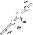
도 2는, 도 1에 따른, 일회용 카세트에 있어서 채널을 따라 다른 액츄에이터가 배열된 것을 개략적으로 표시한 도면.FIG. 2 schematically shows the arrangement of different actuators along a channel in the disposable cassette according to FIG. 1.
도 3은, 본 발명에 따른, 일회용 카세트의 다른 실시예를 상세히 절개하여 사시도로 나타낸 도면.Figure 3 is a perspective view showing in detail a different embodiment of the disposable cassette, according to the present invention.
도 1에 부분적으로 도시된 일회용 카세트(10)에서는, 유체를 안내할 목적에서, 제1부분(12)에 채널 구조(14)가 형성되고, 또, 강성 커버 플레이트 형태인 제2부분(16)에 의해 유체가 새지 않게 밀봉되어 있다. 제1부분(12)의 일부 구역은, 제1부분(12)의 일체화된 부품으로서 신축성 엘라스토머 재료로 만들어져 있지만, 그 밖의 구역은 강성 플라스틱 재료로 구성된다. 일체로 만들어진 이 엘라스토머 구역은 펌프 칼로테(pump calotte)로서 작용한다. 펌프 칼로테는, 도 1에 더 상세하게 나타내지 않지만, 상응하는 액츄에이터에 의해 작동됨으로써 앞뒤로 이동되고, 그 결과, 펌프 칼로테(18)에 의해 밀봉되게 둘러싸인 공간(20)은 부피가 줄거나 커진다. 채널 구조(14)와 연통되는 이 공간(20)은 운반될 유체로 채워져 있어, 엘라스토머 부품, 즉, 펌프 칼로테(18)의 상응하는 변형에 따라 유체가 운반될 수 있다. 이 운반 원리는 막 펌프의 원리와 정확히 일치하고, 분석 기술 분야와 일반적으로 의료 공학 분야 둘 다에서, 이미 원리로서 알려져 있다. 펌프 칼로테로서 작용하는 신축 구역에 인접한 채널 구조(14) 내의 입구 측과 출구 측 각각에 밸브(22, 24)가 제공되는 것이 도 2에 도시되어 있고, 상기 밸브는 펌프에 따라 교대로 개폐되는 역류 방지 밸브로서 부착되어 있다. 이들 구역도, 일회용 카세트(10)의 일부 강성의 제1부분(12)에 대응되게 신축성 있는 일부 구역으로서 만들어질 수 있다. 제1부분(12)은 2-부품 사출 성형 기술을 사용하여 일체로 생산될 수 있다.In the
일회용 카세트(10')의 다른 다양한 실시예는 도 3에 도시되어 있다. 강성 커버 플레이트로 만들어진 제2부분(16)에 의해 아래쪽으로 유체가 새지 않게 폐쇄된 채널 구조(14)는, 유체를 안내할 목적에서 일회용 카세트(10')의 제1부분(12)에 형성되어 있다. 채널 구조(14)는 신축성 엘라스토머 재료로 만들어지고 또 2-부품 사출 성형 기술에 의해 제1부분(12)과 일체로 제조되는 채널 섹션(30)에 의해 흐름 방향으로 개폐될 수 있다. 채널 섹션(30)은 이 일체 형성에 의해 일부 강성의 제1부분(12)의 일체화된 부품으로 되어 있다. 그에 의해 채널 섹션(30)은, 한편으로는 견고하게, 다른 한편으로는 유체가 새지 않는 방식으로 연결된다.Other various embodiments of the disposable cassette 10 'are shown in FIG. The
양쪽 화살표 방향으로, 채널 섹션(30)의 뒤편으로 플런저(plunger, 35)의 힘을 안내하는 것은 그러한 밸브를 밀폐하는데 충분하다. 채널 구조(14)는 이 힘의 방출에 의해 밀폐된다. 밸브의 개방은 밀폐하는 힘을 제거함으로써, 즉, 양쪽 화살표 방향에서의 플런저(35)의 후퇴에 의해 행해지며, 그 결과, 채널 섹션(30)이 탄성 물질의 특성에 의해 본래의 채널 형상으로 다시 복구된다.In both arrow directions, directing the force of the
여기에 도시된 본 실시예에서, 채널 구조(14)는 신축성 엘라스토머부로 연속적으로 만들어진다. 그러나 이와 다르게, 채널 구조는 밸브 자체의 구역에서만 신축성 엘라스토머부로 만들어지고, 다른 채널 구역은 제1부분(12)의 강성 재료에 의해 형성될 수 있다. 신축성 엘라스토머 구역을 향한 힘의 방출은 다양한 방식으로 행해질 수 있다. 한편으로는, 도 3에서 도시된 바와 같이, 플런저(35)를 통한 촉각 방식으로 행해질 수 있다. 그러나 또 다른 한편으로는, 공기역학적으로 압축 공기에 의해 직접 행해진다. 이 경우에, 밀봉 가장자리는 제1부분(12)의 뒤편 밸브 주위에 제공될 것이다. 끝으로, 상기 힘은 기계기구 측에 제공되어야 하는 소형 압력 완충물을 통해 공기역학적으로 또는 수력학적으로, 간접적으로 적용될 수도 있다. 여기서, 매우 작은 밸브 밀폐력에 의해 밀봉 기능이 달성될 수 있다는 것이 특히 이로운 점이다.In this embodiment shown here, the
Claims (7)
Translated fromKoreanApplications Claiming Priority (3)
| Application Number | Priority Date | Filing Date | Title |
|---|---|---|---|
| DE10239597.7 | 2002-08-28 | ||
| DE10239597ADE10239597B4 (en) | 2002-08-28 | 2002-08-28 | disposable cartridge |
| PCT/EP2003/009128WO2004024326A1 (en) | 2002-08-28 | 2003-08-18 | Disposable cassette |
Publications (2)
| Publication Number | Publication Date |
|---|---|
| KR20050046737A KR20050046737A (en) | 2005-05-18 |
| KR101057845B1true KR101057845B1 (en) | 2011-08-19 |
Family
ID=31724146
Family Applications (1)
| Application Number | Title | Priority Date | Filing Date |
|---|---|---|---|
| KR1020057002974AExpired - Fee RelatedKR101057845B1 (en) | 2002-08-28 | 2003-08-18 | Disposable cassette |
Country Status (10)
| Country | Link |
|---|---|
| US (2) | US20050245889A1 (en) |
| EP (1) | EP1534431B1 (en) |
| JP (1) | JP2006503204A (en) |
| KR (1) | KR101057845B1 (en) |
| CN (2) | CN1678396A (en) |
| AT (1) | ATE423621T1 (en) |
| AU (1) | AU2003282002A1 (en) |
| DE (2) | DE10239597B4 (en) |
| ES (1) | ES2319641T3 (en) |
| WO (1) | WO2004024326A1 (en) |
Families Citing this family (21)
| Publication number | Priority date | Publication date | Assignee | Title |
|---|---|---|---|---|
| DE10330804A1 (en) | 2003-07-08 | 2005-04-28 | Fresenius Medical Care De Gmbh | disposable cartridge |
| DE10330803B4 (en)* | 2003-07-08 | 2005-11-17 | Fresenius Medical Care Deutschland Gmbh | Disposable cassette and its use |
| EP1707267A1 (en)* | 2005-03-30 | 2006-10-04 | F. Hoffman-la Roche AG | Device having a self sealing fluid port |
| EP1905514A1 (en)* | 2006-09-30 | 2008-04-02 | Roche Diagnostics GmbH | Device having a reversibly closable fluid valve |
| CA2695486A1 (en)* | 2007-08-21 | 2009-02-26 | Belimo Holding Ag | Flow sensor and production method thereof |
| US20110049054A1 (en)* | 2007-09-20 | 2011-03-03 | Verenium Corporation | Wastewater treatment system |
| DE102009037845A1 (en) | 2009-08-18 | 2011-04-14 | Fresenius Medical Care Deutschland Gmbh | Disposable element, system for pumping and method for pumping a liquid |
| IT1397820B1 (en)* | 2009-12-17 | 2013-02-04 | Silicon Biosystems Spa | MICROFLUID SYSTEM |
| CH702418A1 (en)* | 2009-12-23 | 2011-06-30 | Jean-Denis Rochat | Tape disposable infusion pump for medical and manufacturing method thereof. |
| DE102010020838A1 (en) | 2010-05-18 | 2011-11-24 | Fresenius Medical Care Deutschland Gmbh | Valve assembly for use in extracorporeal blood circulation and method |
| EP2653285B1 (en)* | 2012-04-16 | 2018-10-10 | SABIC Global Technologies B.V. | Providing micro-channels in a plastic substrate |
| US9592507B2 (en)* | 2012-06-22 | 2017-03-14 | Abbott Point Of Care Inc. | Integrated cartridge housings for sample analysis |
| WO2016035817A1 (en) | 2014-09-02 | 2016-03-10 | 株式会社 東芝 | Nucleic acid detection cassette |
| JP6855154B2 (en)* | 2014-09-02 | 2021-04-07 | キヤノンメディカルシステムズ株式会社 | Nucleic acid detection cassette |
| DE202015102187U1 (en) | 2015-04-30 | 2016-08-04 | Ulrich Gmbh & Co. Kg | Device for transferring a fluid |
| WO2018012429A1 (en)* | 2016-07-13 | 2018-01-18 | 株式会社ニコン | Fluid device, method of manufacturing fluid device, and valve for fluid device |
| CN109012768B (en)* | 2017-06-09 | 2021-11-19 | 国家纳米科学中心 | Microfluidic liquid unidirectional flow control structure, chip and method |
| AT520605B1 (en)* | 2017-11-10 | 2020-03-15 | Erba Tech Austria Gmbh | Sensor cassette |
| JP7167434B2 (en)* | 2017-12-13 | 2022-11-09 | 株式会社ニコン | Fluidic device, reservoir supply system and channel supply system |
| CN110131141A (en)* | 2019-03-03 | 2019-08-16 | 浙江师范大学 | An easily maintained self-regulating piezoelectric drug delivery pump |
| CN109763966A (en)* | 2019-03-03 | 2019-05-17 | 浙江师范大学 | An indirect drug delivery pump driven by series cavity piezoelectricity |
Citations (3)
| Publication number | Priority date | Publication date | Assignee | Title |
|---|---|---|---|---|
| US4585623A (en) | 1984-02-27 | 1986-04-29 | Allelix Inc. | Device for performing quantitative chemical and immunochemical assays |
| US5580523A (en) | 1994-04-01 | 1996-12-03 | Bard; Allen J. | Integrated chemical synthesizers |
| WO2002024320A1 (en) | 2000-09-22 | 2002-03-28 | Kawamura Institute Of Chemical Research | Very small chemical device and flow rate adjusting method therefor |
Family Cites Families (12)
| Publication number | Priority date | Publication date | Assignee | Title |
|---|---|---|---|---|
| US4978502A (en)* | 1987-01-05 | 1990-12-18 | Dole Associates, Inc. | Immunoassay or diagnostic device and method of manufacture |
| US5098262A (en)* | 1990-12-28 | 1992-03-24 | Abbott Laboratories | Solution pumping system with compressible pump cassette |
| DE69431994T2 (en)* | 1993-10-04 | 2003-10-30 | Res Int Inc | MICRO-MACHINED FLUID TREATMENT DEVICE WITH FILTER AND CONTROL VALVE |
| EP0862708A4 (en)* | 1995-12-18 | 1998-11-25 | Armand P Neukermans | Microfluidic valve and integrated microfluidic system |
| US6554789B1 (en)* | 1997-02-14 | 2003-04-29 | Nxstage Medical, Inc. | Layered fluid circuit assemblies and methods for making them |
| DE19719862A1 (en)* | 1997-05-12 | 1998-11-19 | Fraunhofer Ges Forschung | Micro diaphragm pump |
| DE29907933U1 (en)* | 1999-05-04 | 1999-08-12 | Georg Menshen GmbH & Co KG, 57413 Finnentrop | Slit closing valve for container openings |
| DE10016017C2 (en)* | 2000-03-31 | 2002-10-17 | Inst Mikrotechnik Mainz Gmbh | Method and assembly device for assembling magazine-mounted micro components |
| DE10046651A1 (en)* | 2000-09-20 | 2002-04-04 | Fresenius Medical Care De Gmbh | Valve |
| JP2002219697A (en) | 2000-09-22 | 2002-08-06 | Kawamura Inst Of Chem Res | Micro fluid device having valve mechanism, and flow control method therefor |
| DE10053441B4 (en)* | 2000-10-27 | 2004-04-15 | Fresenius Medical Care Deutschland Gmbh | Disposable cassette with sealing membrane and valve actuator therefor |
| US6644944B2 (en)* | 2000-11-06 | 2003-11-11 | Nanostream, Inc. | Uni-directional flow microfluidic components |
- 2002
- 2002-08-28DEDE10239597Apatent/DE10239597B4/ennot_activeExpired - Fee Related
- 2003
- 2003-08-18WOPCT/EP2003/009128patent/WO2004024326A1/enactiveApplication Filing
- 2003-08-18AUAU2003282002Apatent/AU2003282002A1/ennot_activeAbandoned
- 2003-08-18DEDE50311225Tpatent/DE50311225D1/ennot_activeExpired - Lifetime
- 2003-08-18KRKR1020057002974Apatent/KR101057845B1/ennot_activeExpired - Fee Related
- 2003-08-18CNCNA038203693Apatent/CN1678396A/enactivePending
- 2003-08-18USUS10/525,668patent/US20050245889A1/ennot_activeAbandoned
- 2003-08-18ESES03773609Tpatent/ES2319641T3/ennot_activeExpired - Lifetime
- 2003-08-18ATAT03773609Tpatent/ATE423621T1/ennot_activeIP Right Cessation
- 2003-08-18JPJP2004535103Apatent/JP2006503204A/enactivePending
- 2003-08-18CNCN201310407456.5Apatent/CN103480311B/ennot_activeExpired - Lifetime
- 2003-08-18EPEP03773609Apatent/EP1534431B1/ennot_activeExpired - Lifetime
- 2010
- 2010-07-13USUS12/805,124patent/US8202489B2/ennot_activeExpired - Fee Related
Patent Citations (3)
| Publication number | Priority date | Publication date | Assignee | Title |
|---|---|---|---|---|
| US4585623A (en) | 1984-02-27 | 1986-04-29 | Allelix Inc. | Device for performing quantitative chemical and immunochemical assays |
| US5580523A (en) | 1994-04-01 | 1996-12-03 | Bard; Allen J. | Integrated chemical synthesizers |
| WO2002024320A1 (en) | 2000-09-22 | 2002-03-28 | Kawamura Institute Of Chemical Research | Very small chemical device and flow rate adjusting method therefor |
Also Published As
| Publication number | Publication date |
|---|---|
| EP1534431A1 (en) | 2005-06-01 |
| KR20050046737A (en) | 2005-05-18 |
| ATE423621T1 (en) | 2009-03-15 |
| WO2004024326A1 (en) | 2004-03-25 |
| JP2006503204A (en) | 2006-01-26 |
| ES2319641T3 (en) | 2009-05-11 |
| CN1678396A (en) | 2005-10-05 |
| EP1534431B1 (en) | 2009-02-25 |
| CN103480311A (en) | 2014-01-01 |
| US20050245889A1 (en) | 2005-11-03 |
| CN103480311B (en) | 2015-08-05 |
| DE50311225D1 (en) | 2009-04-09 |
| US20110070132A1 (en) | 2011-03-24 |
| DE10239597A1 (en) | 2004-03-18 |
| DE10239597B4 (en) | 2005-03-17 |
| AU2003282002A1 (en) | 2004-04-30 |
| US8202489B2 (en) | 2012-06-19 |
Similar Documents
| Publication | Publication Date | Title |
|---|---|---|
| KR101057845B1 (en) | Disposable cassette | |
| US6644944B2 (en) | Uni-directional flow microfluidic components | |
| US20020155010A1 (en) | Microfluidic valve with partially restrained element | |
| US6619311B2 (en) | Microfluidic regulating device | |
| WO2011062557A1 (en) | Improved microfluidic device and method | |
| Lai et al. | Design and dynamic characterization of “single-stroke” peristaltic PDMS micropumps | |
| DE60120230D1 (en) | MICROFABRICATION MANUFACTURED FLUIDIC SWITCHING COMPONENTS AND APPLICATIONS | |
| Napp et al. | Simple passive valves for addressable pneumatic actuation | |
| IL115325A (en) | Valve | |
| JP4344738B2 (en) | Valve device | |
| US10888861B2 (en) | Microfluidic flow control and device | |
| CN1133080A (en) | Micromachined valve apparatus | |
| DE50300749D1 (en) | Pneumatic slide valve with a two-part valve body made of plastic | |
| AU2017208193A1 (en) | Fluidic manifold | |
| Meffan et al. | Transistor off-valve based feedback, metering and logic operations in capillary microfluidics | |
| KR102207911B1 (en) | Flexible valve | |
| KR200444007Y1 (en) | Valve assembly | |
| US11786897B2 (en) | Inert apparatus for microfluidic motion using magnetic shape memory material | |
| US20240125315A1 (en) | Microfluidic pump | |
| US20250314331A1 (en) | Microvalve and Microvalve Array | |
| JP5331547B2 (en) | Liquid discharge pump unit | |
| Henning | Micro-pneumatic logic | |
| JP6224296B2 (en) | Check valve and diaphragm pump | |
| Mosadegh et al. | A monolithic passive check-valve for systematic control of temporal actuation in microfluidic devices |
Legal Events
| Date | Code | Title | Description |
|---|---|---|---|
| PA0105 | International application | St.27 status event code:A-0-1-A10-A15-nap-PA0105 | |
| PG1501 | Laying open of application | St.27 status event code:A-1-1-Q10-Q12-nap-PG1501 | |
| A201 | Request for examination | ||
| PA0201 | Request for examination | St.27 status event code:A-1-2-D10-D11-exm-PA0201 | |
| E902 | Notification of reason for refusal | ||
| PE0902 | Notice of grounds for rejection | St.27 status event code:A-1-2-D10-D21-exm-PE0902 | |
| P11-X000 | Amendment of application requested | St.27 status event code:A-2-2-P10-P11-nap-X000 | |
| P13-X000 | Application amended | St.27 status event code:A-2-2-P10-P13-nap-X000 | |
| E701 | Decision to grant or registration of patent right | ||
| PE0701 | Decision of registration | St.27 status event code:A-1-2-D10-D22-exm-PE0701 | |
| GRNT | Written decision to grant | ||
| PR0701 | Registration of establishment | St.27 status event code:A-2-4-F10-F11-exm-PR0701 | |
| PR1002 | Payment of registration fee | St.27 status event code:A-2-2-U10-U12-oth-PR1002 Fee payment year number:1 | |
| PG1601 | Publication of registration | St.27 status event code:A-4-4-Q10-Q13-nap-PG1601 | |
| R18-X000 | Changes to party contact information recorded | St.27 status event code:A-5-5-R10-R18-oth-X000 | |
| PR1001 | Payment of annual fee | St.27 status event code:A-4-4-U10-U11-oth-PR1001 Fee payment year number:4 | |
| PR1001 | Payment of annual fee | St.27 status event code:A-4-4-U10-U11-oth-PR1001 Fee payment year number:5 | |
| FPAY | Annual fee payment | Payment date:20160801 Year of fee payment:6 | |
| PR1001 | Payment of annual fee | St.27 status event code:A-4-4-U10-U11-oth-PR1001 Fee payment year number:6 | |
| PR1001 | Payment of annual fee | St.27 status event code:A-4-4-U10-U11-oth-PR1001 Fee payment year number:7 | |
| LAPS | Lapse due to unpaid annual fee | ||
| PC1903 | Unpaid annual fee | St.27 status event code:A-4-4-U10-U13-oth-PC1903 Not in force date:20180812 Payment event data comment text:Termination Category : DEFAULT_OF_REGISTRATION_FEE | |
| PC1903 | Unpaid annual fee | St.27 status event code:N-4-6-H10-H13-oth-PC1903 Ip right cessation event data comment text:Termination Category : DEFAULT_OF_REGISTRATION_FEE Not in force date:20180812 |