KR101057670B1 - Sound network transmission system - Google Patents
Sound network transmission systemDownload PDFInfo
- Publication number
- KR101057670B1 KR101057670B1KR1020100036534AKR20100036534AKR101057670B1KR 101057670 B1KR101057670 B1KR 101057670B1KR 1020100036534 AKR1020100036534 AKR 1020100036534AKR 20100036534 AKR20100036534 AKR 20100036534AKR 101057670 B1KR101057670 B1KR 101057670B1
- Authority
- KR
- South Korea
- Prior art keywords
- signal
- sound
- network transmission
- sound source
- analog
- Prior art date
- Legal status (The legal status is an assumption and is not a legal conclusion. Google has not performed a legal analysis and makes no representation as to the accuracy of the status listed.)
- Active
Links
Images


Classifications
- H—ELECTRICITY
- H04—ELECTRIC COMMUNICATION TECHNIQUE
- H04R—LOUDSPEAKERS, MICROPHONES, GRAMOPHONE PICK-UPS OR LIKE ACOUSTIC ELECTROMECHANICAL TRANSDUCERS; DEAF-AID SETS; PUBLIC ADDRESS SYSTEMS
- H04R3/00—Circuits for transducers, loudspeakers or microphones
- H04R3/12—Circuits for transducers, loudspeakers or microphones for distributing signals to two or more loudspeakers
- H—ELECTRICITY
- H04—ELECTRIC COMMUNICATION TECHNIQUE
- H04R—LOUDSPEAKERS, MICROPHONES, GRAMOPHONE PICK-UPS OR LIKE ACOUSTIC ELECTROMECHANICAL TRANSDUCERS; DEAF-AID SETS; PUBLIC ADDRESS SYSTEMS
- H04R1/00—Details of transducers, loudspeakers or microphones
- H04R1/06—Arranging circuit leads; Relieving strain on circuit leads
- H—ELECTRICITY
- H04—ELECTRIC COMMUNICATION TECHNIQUE
- H04R—LOUDSPEAKERS, MICROPHONES, GRAMOPHONE PICK-UPS OR LIKE ACOUSTIC ELECTROMECHANICAL TRANSDUCERS; DEAF-AID SETS; PUBLIC ADDRESS SYSTEMS
- H04R5/00—Stereophonic arrangements
- H04R5/04—Circuit arrangements, e.g. for selective connection of amplifier inputs/outputs to loudspeakers, for loudspeaker detection, or for adaptation of settings to personal preferences or hearing impairments
- H—ELECTRICITY
- H04—ELECTRIC COMMUNICATION TECHNIQUE
- H04R—LOUDSPEAKERS, MICROPHONES, GRAMOPHONE PICK-UPS OR LIKE ACOUSTIC ELECTROMECHANICAL TRANSDUCERS; DEAF-AID SETS; PUBLIC ADDRESS SYSTEMS
- H04R2420/00—Details of connection covered by H04R, not provided for in its groups
- H04R2420/01—Input selection or mixing for amplifiers or loudspeakers
Landscapes
- Physics & Mathematics (AREA)
- Engineering & Computer Science (AREA)
- Acoustics & Sound (AREA)
- Signal Processing (AREA)
- Health & Medical Sciences (AREA)
- General Health & Medical Sciences (AREA)
- Otolaryngology (AREA)
- Two-Way Televisions, Distribution Of Moving Picture Or The Like (AREA)
Abstract
Translated fromKoreanDescription
Translated fromKorean본 발명은 사운드 네트워크 전송시스템에 관한 것으로, 구체적으로 설명하면, 고품질의 A/D, D/A 컨버터를 탑재하여 40개의 아날로그 입출력 신호를 디지털 신호로 전환하여 UTP 케이블(CAT-5)을 통해 최대 100미터까지 전송 가능한 오디오 콘솔로, 아날로그 입력을 디지털 신호로 변환하여주는 트랜스미터(Sound Network Transmission Tx, 송신장비)와 디지털 신호를 다시 아날로그로 변환하여 각 출력부로 전달하여 주는 리시버(Sound Network Transmission Rx, 수신장비)가 한 세트로 구성되어 대형 사운드 시스템에서의 사용시 많은 수의 아날로그 오디오 케이블과 배관비용을 절감할 수 있고, 100미터 이상의 거리로 전송시 이더넷 허브를 이용하여 손쉽게 거리의 연장이 가능하며 아날로그 케이블에서 발생하는 신호 감쇄 및 노이즈 발생 등의 해결이 가능한 사운드 네트워크 전송시스템에 관한 것이다.The present invention relates to a sound network transmission system. Specifically, a high-quality A / D and D / A converters are used to convert 40 analog input / output signals into digital signals, thereby maximizing them through a UTP cable (CAT-5). It is an audio console capable of transmitting up to 100 meters, and includes a transmitter (Sound Network Transmission Tx) that converts analog inputs into digital signals, and a receiver (Sound Network Transmission Rx, which converts digital signals back to analog outputs). Receiving equipment) consists of one set, which can reduce the number of analog audio cable and piping cost when used in a large sound system, and can be easily extended by using an Ethernet hub when transmitting over 100 meters. Sound network that can solve signal attenuation and noise generation from cable It relates to a transmission system.
일반적으로, 사운드 시스템은 아날로그의 음성신호를 전달하도록 이루어진 것으로 음성신호가 스피커로 전송되기까지 많은 케이블과 배관이 형성되며 음성 신호를 송신하는 송신부와 수신하는 수신부가 각 목적에 맞게 설치되게 되어 설치에 따른 비용과 인건비가 증가하게 된다.In general, the sound system is configured to transmit an analog voice signal, and many cables and pipes are formed until the voice signal is transmitted to the speaker, and a transmitter for transmitting the voice signal and a receiver for receiving the voice signal are installed for each purpose. The cost and labor costs will increase.
종래의 사운드 시스템(A')은 도 1에 도시된 바와 같이, 음원발생부(100)인 마이트 잭 박스(101), 무선마이크(102), CD 플레이어(103) 및 카세트 덱(CASSETTE DECK)(104)에서 음원이 발생하게 되면 오디오 믹서(Audio Mixer)(200)에서 음원을 취합하여 볼륨의 조절과 이펙터의 추가로 믹싱할 때 영상 및 음성신호를 전기신호로 바꾸어 다양한 효과를 연출하게 되며 상기 오디오 믹서(200)의 신호는 디지털 신호 처리기(DSP:Digital Signal Processor)(300)로 전달되어 이펙터 추가 및 스피커를 제어하며 EQ(equalizer)로 저음, 중음, 고음 부분의 조절을 통해서 소리의 톤 조절 및 음향주파수를 강조하는 기능을 추가하게 된다.As shown in FIG. 1, the conventional sound system A 'includes a
이렇게 상기 디지털 신호 처리기(300)에서 출력된 음원 신호는 각각의 파워앰프(Power Amp)(400)에 전달되어 증폭 과정을 거쳐 스피커(500)를 통해 전달되어 방출되는 시스템을 갖게 된다.In this way, the sound source signal output from the
이러한 종래의 사운드 시스템은, 아날로그 케이블을 사용하게 되어 여러 개의 상기 스피커(500)를 하나의 시스템으로 제어하고자 할 경우 메인선로에서 개별적으로 해당 파워앰프(400)로 오디오용 케이블(601)이 포설되며 상기 파워앰프(400)에서 각각의 상기 스피커(500)로 스피커 케이블(602)이 포설되게 된다.In such a conventional sound system, when an analog cable is used to control a plurality of the
따라서, 40여 개의 채널을 아날로그 케이블로 전송하게 되면 막대한 양의 케이블이 사용되어, 그 부피와 무게로 인해 배관의 설치가 어렵고 케이블의 포설에 따른 신호 감쇄 및 잡음의 발생과 스피커의 개수에 따라 케이블의 설치비용과 인건비가 증가하게 되며 장거리 신호 전송 시 길어지는 케이블로 인해 선로가 복잡해지며 이동이 어려운 것을 물론 유지보수에 있어서도 어려운 문제점이 있다.Therefore, when 40 channels are transmitted through analog cable, a huge amount of cable is used, which makes it difficult to install the pipe due to its volume and weight, and according to the number of speakers and attenuation of signal and noise caused by cable laying. The installation cost and labor cost of the increase is increased and the cable becomes complicated due to the long cable during the long-distance signal transmission, difficult to move, of course, there is a difficult problem in maintenance.
본 발명의 목적은, 이러한 문제점을 해결하기 위한 것으로, A/D, D/A 컨버터가 탑재된 트랜스미터, 리시버와 UTP 케이블(CAT-5)을 사용하게 되어 트랜스미터와 리시버에서 수신과 송신이 모두 가능하게 되고 이더넷(Ethernet) 네트워크를 통해 40개 채널의 디지털 오디오 신호를 UTP 케이블(CAT-5) 한 가닥으로 동시에 안정적으로 송,수신이 가능하게되어 선로가 간단하게 단순화되며 전기적 저항에 따른 고 음역대의 신호 감쇄 및 노이즈 발생이 방지될 뿐 아니라 허브를 설치하여 100미터인 네트워크 방식의 케이블의 유효거리를 손쉽게 연장할 수 있게 되며 케이블과 배관의 설치 비용과 인건비 및 기존에 코브라넷(Cobranet) 네트워크 인프라가 구축된 곳에 설치할 경우 그의 설치 비용의 절감이 가능하게 되고 유지보수가 용이하게 되는 사운드 네트워크 전송시스템을 제공하는 것이다.An object of the present invention is to solve this problem, and it is possible to use a transmitter, a receiver, and a UTP cable (CAT-5) equipped with A / D and D / A converters, so that both the transmitter and the receiver can receive and transmit. It is possible to transmit and receive 40 channels of digital audio signal through UTP cable (CAT-5) at the same time and stably through Ethernet network. In addition to preventing signal attenuation and noise generation, the hub can be easily installed to extend the effective distance of a 100-meter network cable. The cost and labor costs of cabling and piping, as well as the existing Cobranet network infrastructure, If installed in a built-in sound network transmission system that can reduce its installation cost and facilitate maintenance To provide.
본 발명의 이러한 목적은, 음원발생부와 상기 음원발생부의 음원을 취합하여 볼륨을 조절하는 오디오 믹서와, 상기 오디오 믹서의 아날로그 입력을 디지털 신호로 변환하도록 A/D, D/A 컨버터가 탑재된 트랜스미터(Sound Network Transmission Tx)와, 상기 트랜스미터에서 신호를 받는 허브와, 상기 허브를 거친 신호를 디지털 신호에서 아날로그 신호로 변환하도록 A/D, D/A 컨버터가 탑재된 리시버(Sound Network Transmission Rx)와, 상기 리시버에서 출력된 음원 신호를 증폭하는 파워앰프와, 상기 파워앰프를 통해 증폭된 음원이 방출되는 스피커부를 갖으며, 상기 장비들을 안정적으로 연결하여 신호를 전송하는 UTP케이블(CAT-5)을 포함하는 것을 특징으로 하는 사운드 네트워크 전송시스템에 의해 달성된다.An object of the present invention is to provide an audio mixer for adjusting a volume by combining a sound source generating unit and a sound source of the sound source generating unit, and an A / D and D / A converter to convert an analog input of the audio mixer into a digital signal. Sound Network Transmission Tx, a hub receiving the signal from the transmitter, and a receiver equipped with A / D and D / A converters to convert the signal passing through the hub from a digital signal to an analog signal (Sound Network Transmission Rx) And a power amplifier for amplifying the sound source signal output from the receiver, and a speaker unit for emitting the sound source amplified by the power amplifier, and stably connecting the equipment to transmit a signal (CAT-5). It is achieved by a sound network transmission system comprising a.
본 발명에 따른 사운드 네트워크 전송시스템은, 음원발생부와 상기 음원발생부의 음원을 취합하여 볼륨을 조절하는 오디오 믹서와, 상기 오디오 믹서의 아날로그 입력을 디지털 신호로 변환하도록 A/D, D/A 컨버터가 탑재된 트랜스미터(Sound Network Transmission Tx)와, 상기 트랜스미터에서 신호를 받는 허브와, 상기 허브를 거친 신호를 디지털 신호에서 아날로그 신호로 변환하도록 A/D, D/A 컨버터가 탑재된 리시버(Sound Network Transmission Rx)와, 상기 리시버에서 출력된 음원 신호를 증폭하는 파워앰프와, 상기 파워앰프를 통해 증폭된 음원이 방출되는 스피커부를 갖으며, 상기 장비들을 안정적으로 연결하여 신호를 전송하는 UTP케이블(CAT-5)을 포함하는 구조로 트랜스미터와 리시버에서 송, 수신이 가능하며 이더넷(Ethernet) 네트워크를 통해 40개의 채널의 디지털 오디오 신호를 UTP 케이블(CAT-5) 한 가닥으로 동시에 안정적으로 송,수신이 가능하며 전기적 저항에 따른 고음 역대 신호 감쇄 및 노이즈 발생이 방지될 뿐 아니라 100미터인 네트워크 방식의 케이블의 유효거리를 허브를 설치하여 손쉽게 연장할 수 있으며 케이블과 배관의 설치 비용과 인건비 및 기존에 코브라넷(Cobranet) 네트워크 인프라가 구축된 곳에 설치할 경우 그의 설치 비용의 절감이 가능하게 되고 유지보수가 용이한 효과가 있다.The sound network transmission system according to the present invention includes an audio mixer for adjusting a volume by collecting a sound source generator and a sound source of the sound source generator, and an A / D and D / A converter to convert analog inputs of the audio mixer into digital signals. Sound Network Transmission Tx, a hub receiving the signal from the transmitter, and a receiver equipped with an A / D, D / A converter to convert the signal through the hub from a digital signal to an analog signal (Sound Network) Transmission Rx), a power amplifier for amplifying the sound source signal output from the receiver, and a speaker unit for emitting the amplified sound source through the power amplifier, UTP cable (CAT) for stably connecting the equipment to transmit the signal -5) structure, which can transmit and receive from transmitters and receivers, and digitally converts 40 channels through Ethernet network. It is possible to transmit / receive video signal stably with one strand of UTP cable (CAT-5) at the same time, and to prevent high-frequency signal attenuation and noise generation due to electrical resistance, and to measure the effective distance of 100-meter network cable. The installation cost can be easily extended by installing and installing cables and pipes, labor costs, and installation in existing Cobranet network infrastructures, which can reduce their installation costs and facilitate maintenance.
도 1은 종래의 사운드 시스템의 구성도
도 2는 본 발명에 따른 사운드 네트워크 전송시스템의 구성도
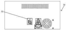
도 3a는 본 발명에 따른 사운드 네트워크 전송시스템의 트랜스미터의 전면도
도 3b는 본 발명에 따른 사운드 네트워크 전송시스템의 트랜스미터의 후면도
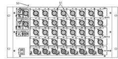
도 4a는 본 발명에 따른 사운드 네트워크 전송시스템의 리시버의 전면도
도 4b는 본 발명에 따른 사운드 네트워크 전송시스템의 리시버의 후면도1 is a block diagram of a conventional sound system
2 is a block diagram of a sound network transmission system according to the present invention;
3A is a front view of a transmitter of the sound network transmission system according to the present invention.
3B is a rear view of the transmitter of the sound network transmission system according to the present invention.
4A is a front view of a receiver of a sound network transmission system according to the present invention.
4b is a rear view of a receiver of a sound network transmission system according to the present invention;
본 발명의 제1실시예에 따른 사운드 네트워크 전송시스템(A)은, 도 2에 도시된 바와 같이, 음원발생부(10)와 상기 음원발생부(10)의 음원을 취합하여 볼륨을 조절하는 오디오 믹서(20)와, 상기 오디오 믹서(20)의 아날로그 입력을 디지털 신호로 변환하도록 A/D, D/A 컨버터가 탑재된 트랜스미터(Sound Network Transmission Tx)(30)와, 상기 트랜스미터(30)에서 신호를 받는 허브(40)와, 상기 허브(40)를 거친 신호를 디지털 신호에서 아날로그 신호로 변환하도록 A/D, D/A 컨버터가 탑재된 리시버(Sound Network Transmission Rx)(50)와, 상기 리시버(50)에서 출력된 음원 신호를 증폭하는 파워앰프(60)와, 상기 파워앰프(60)를 통해 증폭된 음원이 방출되는 스피커부(70)를 갖으며, 상기 장비들을 안정적으로 연결하여 신호를 전송하는 UTP케이블(CAT-5)(80)을 포함하는 구조로 구성된다.In the sound network transmission system A according to the first embodiment of the present invention, as shown in FIG. 2, the sound
상기 음원발생부(10)는 마이크 잭 박스(11), 무선마이크(12), CD플레이어(13) 및 카세트 덱(14)을 통해 아날로그 음성신호가 인입되어 음원을 발생하는 부분이다.The sound
상기 음원발생부(10)의 마이크 잭 박스(11)는 무대 전면 바닥이나 무대 옆 벽면에 설치되는 것으로 종래에는 다수의 케이블과 배관이 설치되어 형성되었으나 후술되는 UTP케이블(CAT-5)(80)을 배관배선으로 사용하게 되어 선로가 단순화되며 후술되는 리시버(50)로 신호가 전송되고 나머지 상기 음원발생부(10)의 무선마이크(12), CD플레이어(13) 및 카세트 덱(14)은 기존의 오디오 케이블에 의해 오디오 믹서(20)로 신호를 전송하게 된다.The
상기 오디오 믹서(20)는 상기 음원발생부(10)에서 발생하는 음원을 취합하여 볼륨을 조절하고 영상, 음성신호 등을 전기신호로 바꿔 다양한 효과를 연출하는 이펙터(effector)를 추가하며 이펙터는 음원을 믹싱하는 데에 사용하고 전자 악기와 앰프 사이에 설치되는 소형장비로써 대표적으로 코러스(chorus), 이퀄라이저(equalizer), 컴프레서(compressor), 디스토션(distortion) 및 딜레이(delay) 등이 이펙터의 장비이다.The
상기 오디로 믹서(20)는 상기 음원발생부(10)의 무선마이크(12), CD플레이어(13) 및 카세트 덱(14)의 신호가 바로 전송되며 상기 마이크 잭 박스(11)의 신호는 신호변환과정을 거친 후에 상기 오디오 믹서(20)로 전송된다.The
상기 트랜스미터(Sound Network Transmission Tx)(30)는 A/D, D/A 컨버터가 탑재된 것으로 송신지에 설치되나 송신과 수신이 가능하며 상기 오디오 믹서(20)의 아날로그 입력신호를 디지털 신호로 변환한다.The transmitter (Sound Network Transmission Tx) 30 is equipped with an A / D, D / A converter, which is installed at a transmission site, but can transmit and receive, and converts an analog input signal of the
도 3a, 3b에 도시된 바와 같이 상기 트랜스미터(Sound Network Transmission Tx)(30)의 아날로그 인 XLR 잭(Analog In XLR Jack)(31)에 상기 음원발생부(10) 및 오디오 믹서(20)가 연결되며 이더넷 커넥터 100 베이스 티(Ethernet Connector 100base-T)(32)에 상기 UTP케이블(CAT-5)(80)을 이용하여 후술되는 허브(40)와 연결되며 상기 이더넷 커넥터 100 베이스 티(32)는 전송속도가 100Mbps로 동시에 신호를 전송하는 멀티플렉싱을 위하여 신호를 더 높고 효율적인 주파수대역으로 변조시키기 이전의 원래 주파수대역으로 이더넷 신호만이 전송되게 된다.As shown in FIGS. 3A and 3B, the
상기 트랜스미터(30)의 아날로그 게인 조절(Analog Gain 조절)(33)은 +20dB 내지 -20dB의 범위에서 입력된 신호를 감쇄하거나 증폭하여 후술되는 리시버(50)로 보내며 클리핑 레벨 LED 아날로그(Clipping Level LED Analog)(34)를 통해 과입력이 들어오면 LED를 통해 표시되는 것으로 상기 아날로그 게인 조절(33)의 볼륨의 위치가 0dB 일때 실효치가 +2 Vrms이상으로 들어오면 LED가 점등된다.The
상기 허브(40)는 상기 트랜스미터(30)의 이더넷 커넥터 100 베이스 티(32)와 상기 UTP 케이블(CAT-5)(80)에 의해 연결되는 것으로 권장사양은 100Mbps 이상이며 여러 대의 장비를 연결하는 연결점 역할을 하며 상기 UTP 케이블(CAT-5)(80)의 100미터의 유효거리를 보다 연장하고자 할 때 사용하는 장치이므로 필요에 따라 상기 허브(40)가 설치되거나 그렇지 않을 수 있다.The
상기 리시버(Sound Network Transmission Rx)(50)는 A/D, D/A 컨버터가 탑재된 것으로 수신지에 설치되며 상기 리시버(50)도 상기 트랜스미터(30)와 마찬가지로 송신과 수신이 가능하게 되며 상기 허브(40)로 부터 전송되는 디지털 신호를 아날로그 신호로 변환하며 도 4a, 4b에 도시된 바와 같이 상기 리시버(50)의 이더넷 커넥터 100 베이스 티(Ethernet Connector 100base-T)(52)에 UTP 케이블(CAT-5)(80)을 사용하여 상기 허브(40)와 연결되며 아날로그 아웃 XLR 잭(Analog Out XLR Jack)(51)을 통해 상기 음원발생부(10)의 다수 신호가 전송되게 되며 파워앰프(60) 및 스피커(71)가 연결된다.The receiver (Sound Network Transmission Rx) 50 is equipped with an A / D, D / A converter is installed in the destination, and the
상기 파워앰프(60)는 음원 신호를 증폭시키는 것으로 상기 리시버(50)로부터 전송된 음원 신호를 고출력을 얻을 수 있도록 증폭과정을 거쳐 후술되는 스피커(71)로 전송한다.The
상기 스피커부(70)는 음원 신호를 방출하기 위한 것으로 상기 파워앰프(60)에 의해 증폭된 신호를 받아 방출하는 스피커(71)와 디지털 신호를 받을 수 있는 파워드 스피커(72)가 있으며 상기 파워드 스피커(72)는 앰프가 내장되어 있어 상기 트랜스미터(30)의 음원 신호를 별도의 신호 변환을 거치지 않고 바로 방출할 수 있다.The
상기 UTP 케이블(Unshielded Twisted Pair Cable)(CAT-5)(80)은 두 개의 구리선을 꼬아서 만든 여러 개의 쌍 케이블의 외부를 플라스틱으로 감싸 전류가 통하지 않도록 만든 유효거리가 100미터인 선으로 상기 UTP케이블의 종류 중 CAT-5는 100Mbps의 최대 전송속도를 갖는 케이블이며 장비 간의 연결을 상기 UTP케이블(CAT-5)(80) 1가닥으로 시스템을 구성할 수 있다.The UTP cable (Unshielded Twisted Pair Cable) (CAT-5) (80) is a wire having an effective distance of 100 meters made of a current wrapped around the outside of several pair cables made by twisting two copper wires with plastic so that no current passes through the UTP cable. CAT-5 is a cable having a maximum transmission rate of 100 Mbps among the types of cables, the system can be configured to connect the UTP cable (CAT-5) 80 with one strand between the equipment.
이러한 상기 UTP 케이블(CAT-5)(80)은 인건비, 배선 및 배관 등의 원가절감이 가능하며 전기적 저항에 따른 신호 감쇄 및 노이즈 발생을 근본적으로 해결하게 된다.The UTP cable (CAT-5) 80 can reduce the cost of labor, wiring and piping, and fundamentally solves signal attenuation and noise generation due to electrical resistance.
본 발명에 따른 사운드 네트워크 전송시스템(A)에 대해서 자세하게 설명하면, 음원발생부(10)의 마이크 잭 박스(11)로 인입된 음원은 UTP 케이블(CAT-5)(80)로 리시버(50)의 아날로그 아웃 XLR 잭(51)에 연결되어 상기 리시버(50)에 전송되어 아날로그 음성 신호를 디지털 신호로 변환하게 되며 변환된 음원 신호는 상기 리시버(50)의 이더넷 커넥터 100 베이스 티(52)에 UTP 케이블(CAT-5)(80)로 허브(40)와 연결되며 상기 허브(40)는 트랜스미터(30)의 이더넷 커넥터 100 베이스 티(32)와 연결되어 전송된 디지털 신호를 아날로그 신호로 변환하여 음원 신호를 오디오 믹서(20)로 전달하게 된다.The sound network transmission system A according to the present invention will be described in detail. The sound source introduced into the
상기 오디오 믹서(20)로 전달된 상기 음원발생부(10)의 마이크 잭 박스(11)의 음원 신호와 상기 음원발생부(10)의 무선마이크(12), CD플레이어(13) 및 카세트 덱(14)으로 인입된 음원신호는 상기 오디오 믹서(20)에서 음원의 취합과 다양한 효과가 더해져 음원이 믹싱된다.The sound source signal of the
상기 오디오믹서(20)는 상기 트랜스미터(30)의 아날로그 아웃 XLR 잭(31)과 연결되어 상기 트랜스미터(30)로 음원 신호가 전달되어 아날로그 신호를 디지털 신호로 변환한 후 상기 트랜스미터(30)의 이더넷 커넥터 100 베이스 티(32)에 상기 허브(40)와 연결되며 상기 허브(40)는 상기 리시버(50)의 상기 이더넷 커넥터 100 베이스 티(52)와 연결되고 상기 리시버(50)에서 전달된 디지털 음원 신호를 아날로그 신호로 변환하게 된다. 상기 리시버(50)의 아날로그 아웃 XLR 잭(51)에 파워엠프(60)가 연결되어 변환된 신호가 상기 파워앰프(60)로 전달되어 음원 신호가 증폭되며 이렇게 증폭된 신호는 스피커(71)을 통해 방출되게 된다.The
또한, 파워드 스피커(72)와 같이 디지털 신호를 받을 수 있는 장비가 구비되면 상기 트랜스미터(30)를 통해 변환된 디지털 음원 신호를 별도의 신호 변환을 거치지 않고 상기 허브(40)를 거쳐 상기 파워드 스피커(72)를 통해 방출되게 된다.In addition, when a device capable of receiving a digital signal, such as a
상기 장비들 간의 연결은 대부분 UTP 케이블(CAT-5)(80) 한 가닥으로 연결되게 되어 배관과 배선의 사용이 줄어 설치가 용이하며 인건비와 원가 절감의 효과가 있으며 전기적 저항에 따른 신호 감쇄 및 노이즈의 발생을 줄이고 안정적인 디지털 신호의 전송이 가능하게 된다.
Most of the connection between the equipment is connected by one strand of UTP cable (CAT-5) (80), reducing the use of piping and wiring, easy installation, labor cost and cost saving effect, signal attenuation and noise due to electrical resistance It is possible to reduce the occurrence of and to transmit a stable digital signal.
10. 음원발생부11. 마이크 잭 박스12. 무선마이크
13. CD플레이어14. 카세트 덱20. 오디오믹서
30. 트랜스미터31,51. 아날로그 인 XLR 잭
32,52. 이더넷커넥터100베이스티33. 아날로그 게인 조절
34. 클리핑 레벨 LED 아날로그 40. 허브50. 리시버
60. 파워앰프70. 스피커부71. 스피커
72. 파워드스피커80. UTP 케이블(CAT-5)10. Sound
13.
30.
32,52.
34. Clipping
60.
72. Powered
Claims (3)
Translated fromKorean사운드 네트워크 전송시스템은, 음원발생부(10)와 상기 음원발생부(10)의 음원을 취합하여 볼륨을 조절하는 오디오 믹서(20)와,
상기 오디오 믹서(20)의 아날로그 입력을 디지털 신호로 변환하도록 A/D, D/A 컨버터가 탑재된 트랜스미터(Sound Network Transmission Tx)(30)와,
상기 트랜스미터(30)에서 신호를 받는 허브(40)와,
상기 허브(40)를 거친 신호를 디지털 신호에서 아날로그 신호로 변환하도록 A/D, D/A 컨버터가 탑재된 리시버(Sound Network Transmission Rx)(50)와,
상기 리시버(50)에서 출력된 음원 신호를 증폭하는 파워앰프(60)와,
상기 파워앰프(60)를 통해 증폭된 음원이 방출되는 스피커부(70)를 갖으며,
상기 오디오 믹서(20), 트랜스미터(30), 허브(40), 리시버(50), 파워앰프(60), 및 스피커부(70)를 안정적으로 연결하여 신호를 전송하는 UTP케이블(CAT-5)(80)을 포함하는 것을 특징으로 하는 사운드 네트워크 전송시스템In the sound network transmission system (A),
The sound network transmission system includes: an audio mixer 20 for adjusting a volume by collecting a sound source generator 10 and a sound source of the sound source generator 10;
A transmitter (Sound Network Transmission Tx) 30 equipped with an A / D and D / A converter to convert the analog input of the audio mixer 20 into a digital signal,
Hub 40 receiving the signal from the transmitter 30,
A receiver (Sound Network Transmission Rx) 50 equipped with an A / D and D / A converter to convert the signal passed through the hub 40 into an analog signal;
A power amplifier 60 for amplifying a sound source signal output from the receiver 50;
Has a speaker unit 70 for emitting a sound source amplified by the power amplifier 60,
UTP cable (CAT-5) for stably connecting the audio mixer 20, the transmitter 30, the hub 40, the receiver 50, the power amplifier 60, and the speaker unit 70 to transmit a signal Sound network transmission system, characterized in that it comprises an 80
상기 음원발생부(10)는 마이크 잭 박스(11)를 포함하며,
상기 마이크 잭 박스(11)는 상기 리시버(50)의 아날로그 아웃 XLR 잭(51)에 연결되어 아날로그 음성 신호를 디지털 신호로 변환하게 되며 음원 신호는 상기 리시버(50)의 이더넷 커넥터 100 베이스 티(52)를 통해 허브(40)와 연결되며 상기 허브(40)는 트랜스미터(30)의 이더넷 커넥터 100 베이스 티(32)와 연결되어 디지털 신호를 아날로그 신호로 변환하여 음원 신호를 오디오 믹서(20)로 전달되며, UTP케이블(CAT-5)(80)로 연결되는 것을 특징으로 하는 사운드 네트워크 전송시스템The method of claim 1,
The sound source generation unit 10 includes a microphone jack box 11,
The microphone jack box 11 is connected to the analog out XLR jack 51 of the receiver 50 to convert an analog voice signal into a digital signal, and the sound source signal is an Ethernet connector 100 base tee 52 of the receiver 50. Is connected to the hub 40 and the hub 40 is connected to the Ethernet connector 100 base tee 32 of the transmitter 30 to convert a digital signal into an analog signal and transmit a sound source signal to the audio mixer 20. Sound network transmission system, characterized in that connected by UTP cable (CAT-5) (80)
상기 트랜스미터(30)와 상기 리시버(50)는 A/D, D/A 컨버터가 탑재되어 있으며 송신과 수신이 모두 가능한 것을 특징으로 하는 사운드 네트워크 전송시스템
The method of claim 1,
The transmitter 30 and the receiver 50 are equipped with A / D and D / A converters, and are capable of transmitting and receiving sound network transmission systems.
Priority Applications (1)
| Application Number | Priority Date | Filing Date | Title |
|---|---|---|---|
| KR1020100036534AKR101057670B1 (en) | 2010-04-20 | 2010-04-20 | Sound network transmission system |
Applications Claiming Priority (1)
| Application Number | Priority Date | Filing Date | Title |
|---|---|---|---|
| KR1020100036534AKR101057670B1 (en) | 2010-04-20 | 2010-04-20 | Sound network transmission system |
Publications (1)
| Publication Number | Publication Date |
|---|---|
| KR101057670B1true KR101057670B1 (en) | 2011-08-18 |
Family
ID=44933446
Family Applications (1)
| Application Number | Title | Priority Date | Filing Date |
|---|---|---|---|
| KR1020100036534AActiveKR101057670B1 (en) | 2010-04-20 | 2010-04-20 | Sound network transmission system |
Country Status (1)
| Country | Link |
|---|---|
| KR (1) | KR101057670B1 (en) |
Cited By (3)
| Publication number | Priority date | Publication date | Assignee | Title |
|---|---|---|---|---|
| WO2014175482A1 (en)* | 2013-04-24 | 2014-10-30 | (주)씨어스테크놀로지 | Musical accompaniment device and musical accompaniment system using ethernet audio transmission function |
| KR101469939B1 (en)* | 2013-04-24 | 2014-12-08 | (주)씨어스테크놀로지 | System and Device for Musical Accompaniment using Ethernet Audio Bridging |
| KR101927740B1 (en)* | 2017-06-19 | 2018-12-11 | 이재호 | On-site Audio Center system based on Audio over IP |
Citations (2)
| Publication number | Priority date | Publication date | Assignee | Title |
|---|---|---|---|---|
| KR100512473B1 (en) | 2004-11-30 | 2005-09-02 | 이종성 | Network audio speaker system |
| KR100550838B1 (en) | 2003-10-24 | 2006-02-10 | 주식회사 영전 | Integrated Broadcasting System |
- 2010
- 2010-04-20KRKR1020100036534Apatent/KR101057670B1/enactiveActive
Patent Citations (2)
| Publication number | Priority date | Publication date | Assignee | Title |
|---|---|---|---|---|
| KR100550838B1 (en) | 2003-10-24 | 2006-02-10 | 주식회사 영전 | Integrated Broadcasting System |
| KR100512473B1 (en) | 2004-11-30 | 2005-09-02 | 이종성 | Network audio speaker system |
Cited By (5)
| Publication number | Priority date | Publication date | Assignee | Title |
|---|---|---|---|---|
| WO2014175482A1 (en)* | 2013-04-24 | 2014-10-30 | (주)씨어스테크놀로지 | Musical accompaniment device and musical accompaniment system using ethernet audio transmission function |
| KR101469939B1 (en)* | 2013-04-24 | 2014-12-08 | (주)씨어스테크놀로지 | System and Device for Musical Accompaniment using Ethernet Audio Bridging |
| KR101927740B1 (en)* | 2017-06-19 | 2018-12-11 | 이재호 | On-site Audio Center system based on Audio over IP |
| WO2018236005A1 (en)* | 2017-06-19 | 2018-12-27 | 이재호 | AOIP-based on-site acoustic center system |
| US11088899B2 (en) | 2017-06-19 | 2021-08-10 | Jae Ho Lee | On-site audio center system based on audio over IP |
Similar Documents
| Publication | Publication Date | Title |
|---|---|---|
| US8385561B2 (en) | Digital power link audio distribution system and components thereof | |
| US11765532B2 (en) | Digital audio communication and control in a live performance venue | |
| US20040037433A1 (en) | Multi-channel wireless professional audio system | |
| TW200951938A (en) | Systems for combining inputs from electronic musical instruments and devices | |
| US9894494B2 (en) | System, apparatus and method for configuring a wireless sound reinforcement system | |
| KR101057670B1 (en) | Sound network transmission system | |
| US8879754B2 (en) | Sound reproducing system with superimposed digital signal | |
| CN106792350A (en) | A kind of device of compatible various Audio Signal Processings | |
| US20020094807A1 (en) | Signal routing for reduced power consumption in a conferencing system | |
| CN102014329A (en) | Low-pitch compensating method and device of electronic device speaker | |
| KR101106681B1 (en) | Two-way digital conversion audio transmission system | |
| JPH02204794A (en) | Ensemble system | |
| US11755274B2 (en) | Hybrid input networked audio subwoofer | |
| JP4967575B2 (en) | Audio conferencing equipment | |
| JP6969604B2 (en) | Headphones | |
| WO2023059214A1 (en) | Modular audio system for public passenger transportation vehicles | |
| JP3128487U (en) | General-purpose wireless transmission / reception system for karaoke that can individually adjust the output of the sound source (song accompaniment and microphone sound) | |
| Lee et al. | Implementation of on-site audio center based on AoIP | |
| KR101041981B1 (en) | Signal processing unit | |
| CN201766699U (en) | Low sound supplementary device for audio unit of electronic equipment | |
| JP4470136B2 (en) | Infrared wireless microphone system | |
| CN219395025U (en) | Audio centralized processor | |
| KR100923872B1 (en) | Audio signal output device of home theater system and signal output method using same | |
| CN207766527U (en) | Audio conversion equipment and multi-sound system | |
| CN219761300U (en) | Sound enhancement system and sound playing system |
Legal Events
| Date | Code | Title | Description |
|---|---|---|---|
| A201 | Request for examination | ||
| PA0109 | Patent application | St.27 status event code:A-0-1-A10-A12-nap-PA0109 | |
| PA0201 | Request for examination | St.27 status event code:A-1-2-D10-D11-exm-PA0201 | |
| D13-X000 | Search requested | St.27 status event code:A-1-2-D10-D13-srh-X000 | |
| D14-X000 | Search report completed | St.27 status event code:A-1-2-D10-D14-srh-X000 | |
| E701 | Decision to grant or registration of patent right | ||
| PE0701 | Decision of registration | St.27 status event code:A-1-2-D10-D22-exm-PE0701 | |
| GRNT | Written decision to grant | ||
| PR0701 | Registration of establishment | St.27 status event code:A-2-4-F10-F11-exm-PR0701 | |
| PR1002 | Payment of registration fee | St.27 status event code:A-2-2-U10-U11-oth-PR1002 Fee payment year number:1 | |
| PG1601 | Publication of registration | St.27 status event code:A-4-4-Q10-Q13-nap-PG1601 | |
| FPAY | Annual fee payment | Payment date:20140801 Year of fee payment:4 | |
| PR1001 | Payment of annual fee | St.27 status event code:A-4-4-U10-U11-oth-PR1001 Fee payment year number:4 | |
| FPAY | Annual fee payment | Payment date:20150806 Year of fee payment:5 | |
| PR1001 | Payment of annual fee | St.27 status event code:A-4-4-U10-U11-oth-PR1001 Fee payment year number:5 | |
| P22-X000 | Classification modified | St.27 status event code:A-4-4-P10-P22-nap-X000 | |
| FPAY | Annual fee payment | Payment date:20160722 Year of fee payment:6 | |
| PR1001 | Payment of annual fee | St.27 status event code:A-4-4-U10-U11-oth-PR1001 Fee payment year number:6 | |
| FPAY | Annual fee payment | Payment date:20170727 Year of fee payment:7 | |
| PR1001 | Payment of annual fee | St.27 status event code:A-4-4-U10-U11-oth-PR1001 Fee payment year number:7 | |
| PN2301 | Change of applicant | St.27 status event code:A-5-5-R10-R13-asn-PN2301 St.27 status event code:A-5-5-R10-R11-asn-PN2301 | |
| PN2301 | Change of applicant | St.27 status event code:A-5-5-R10-R13-asn-PN2301 St.27 status event code:A-5-5-R10-R11-asn-PN2301 | |
| R18-X000 | Changes to party contact information recorded | St.27 status event code:A-5-5-R10-R18-oth-X000 | |
| P22-X000 | Classification modified | St.27 status event code:A-4-4-P10-P22-nap-X000 | |
| P14-X000 | Amendment of ip right document requested | St.27 status event code:A-5-5-P10-P14-nap-X000 | |
| P16-X000 | Ip right document amended | St.27 status event code:A-5-5-P10-P16-nap-X000 | |
| Q16-X000 | A copy of ip right certificate issued | St.27 status event code:A-4-4-Q10-Q16-nap-X000 | |
| PR1001 | Payment of annual fee | St.27 status event code:A-4-4-U10-U11-oth-PR1001 Fee payment year number:8 | |
| PR1001 | Payment of annual fee | St.27 status event code:A-4-4-U10-U11-oth-PR1001 Fee payment year number:9 | |
| PR1001 | Payment of annual fee | St.27 status event code:A-4-4-U10-U11-oth-PR1001 Fee payment year number:10 | |
| PR1001 | Payment of annual fee | St.27 status event code:A-4-4-U10-U11-oth-PR1001 Fee payment year number:11 | |
| S20-X000 | Security interest recorded | St.27 status event code:A-4-4-S10-S20-lic-X000 | |
| PR1001 | Payment of annual fee | St.27 status event code:A-4-4-U10-U11-oth-PR1001 Fee payment year number:12 | |
| PR1001 | Payment of annual fee | St.27 status event code:A-4-4-U10-U11-oth-PR1001 Fee payment year number:13 | |
| PR1001 | Payment of annual fee | St.27 status event code:A-4-4-U10-U11-oth-PR1001 Fee payment year number:14 | |
| PR1001 | Payment of annual fee | St.27 status event code:A-4-4-U10-U11-oth-PR1001 Fee payment year number:15 |