KR101057188B1 - Method for manufacturing PMOS transistor and method for forming dual gate of semiconductor device using same - Google Patents
Method for manufacturing PMOS transistor and method for forming dual gate of semiconductor device using sameDownload PDFInfo
- Publication number
- KR101057188B1 KR101057188B1KR1020080111581AKR20080111581AKR101057188B1KR 101057188 B1KR101057188 B1KR 101057188B1KR 1020080111581 AKR1020080111581 AKR 1020080111581AKR 20080111581 AKR20080111581 AKR 20080111581AKR 101057188 B1KR101057188 B1KR 101057188B1
- Authority
- KR
- South Korea
- Prior art keywords
- polysilicon film
- forming
- doping
- film
- boron
- Prior art date
- Legal status (The legal status is an assumption and is not a legal conclusion. Google has not performed a legal analysis and makes no representation as to the accuracy of the status listed.)
- Expired - Fee Related
Links
Images


Classifications
- H—ELECTRICITY
- H01—ELECTRIC ELEMENTS
- H01L—SEMICONDUCTOR DEVICES NOT COVERED BY CLASS H10
- H01L21/00—Processes or apparatus adapted for the manufacture or treatment of semiconductor or solid state devices or of parts thereof
- H01L21/02—Manufacture or treatment of semiconductor devices or of parts thereof
- H01L21/04—Manufacture or treatment of semiconductor devices or of parts thereof the devices having potential barriers, e.g. a PN junction, depletion layer or carrier concentration layer
- H01L21/18—Manufacture or treatment of semiconductor devices or of parts thereof the devices having potential barriers, e.g. a PN junction, depletion layer or carrier concentration layer the devices having semiconductor bodies comprising elements of Group IV of the Periodic Table or AIIIBV compounds with or without impurities, e.g. doping materials
- H01L21/28—Manufacture of electrodes on semiconductor bodies using processes or apparatus not provided for in groups H01L21/20 - H01L21/268
- H01L21/28008—Making conductor-insulator-semiconductor electrodes
- H01L21/28017—Making conductor-insulator-semiconductor electrodes the insulator being formed after the semiconductor body, the semiconductor being silicon
- H01L21/28026—Making conductor-insulator-semiconductor electrodes the insulator being formed after the semiconductor body, the semiconductor being silicon characterised by the conductor
- H01L21/28035—Making conductor-insulator-semiconductor electrodes the insulator being formed after the semiconductor body, the semiconductor being silicon characterised by the conductor the final conductor layer next to the insulator being silicon, e.g. polysilicon, with or without impurities
- H—ELECTRICITY
- H10—SEMICONDUCTOR DEVICES; ELECTRIC SOLID-STATE DEVICES NOT OTHERWISE PROVIDED FOR
- H10D—INORGANIC ELECTRIC SEMICONDUCTOR DEVICES
- H10D64/00—Electrodes of devices having potential barriers
- H10D64/60—Electrodes characterised by their materials
- H10D64/66—Electrodes having a conductor capacitively coupled to a semiconductor by an insulator, e.g. MIS electrodes
- H10D64/661—Electrodes having a conductor capacitively coupled to a semiconductor by an insulator, e.g. MIS electrodes the conductor comprising a layer of silicon contacting the insulator, e.g. polysilicon having vertical doping variation
- H10D64/662—Electrodes having a conductor capacitively coupled to a semiconductor by an insulator, e.g. MIS electrodes the conductor comprising a layer of silicon contacting the insulator, e.g. polysilicon having vertical doping variation the conductor further comprising additional layers, e.g. multiple silicon layers having different crystal structures
- H—ELECTRICITY
- H01—ELECTRIC ELEMENTS
- H01L—SEMICONDUCTOR DEVICES NOT COVERED BY CLASS H10
- H01L21/00—Processes or apparatus adapted for the manufacture or treatment of semiconductor or solid state devices or of parts thereof
- H01L21/02—Manufacture or treatment of semiconductor devices or of parts thereof
- H01L21/04—Manufacture or treatment of semiconductor devices or of parts thereof the devices having potential barriers, e.g. a PN junction, depletion layer or carrier concentration layer
- H01L21/18—Manufacture or treatment of semiconductor devices or of parts thereof the devices having potential barriers, e.g. a PN junction, depletion layer or carrier concentration layer the devices having semiconductor bodies comprising elements of Group IV of the Periodic Table or AIIIBV compounds with or without impurities, e.g. doping materials
- H01L21/22—Diffusion of impurity materials, e.g. doping materials, electrode materials, into or out of a semiconductor body, or between semiconductor regions; Interactions between two or more impurities; Redistribution of impurities
- H01L21/223—Diffusion of impurity materials, e.g. doping materials, electrode materials, into or out of a semiconductor body, or between semiconductor regions; Interactions between two or more impurities; Redistribution of impurities using diffusion into or out of a solid from or into a gaseous phase
- H—ELECTRICITY
- H10—SEMICONDUCTOR DEVICES; ELECTRIC SOLID-STATE DEVICES NOT OTHERWISE PROVIDED FOR
- H10D—INORGANIC ELECTRIC SEMICONDUCTOR DEVICES
- H10D84/00—Integrated devices formed in or on semiconductor substrates that comprise only semiconducting layers, e.g. on Si wafers or on GaAs-on-Si wafers
- H10D84/01—Manufacture or treatment
- H10D84/0123—Integrating together multiple components covered by H10D12/00 or H10D30/00, e.g. integrating multiple IGBTs
- H10D84/0126—Integrating together multiple components covered by H10D12/00 or H10D30/00, e.g. integrating multiple IGBTs the components including insulated gates, e.g. IGFETs
- H10D84/0165—Integrating together multiple components covered by H10D12/00 or H10D30/00, e.g. integrating multiple IGBTs the components including insulated gates, e.g. IGFETs the components including complementary IGFETs, e.g. CMOS devices
- H10D84/0172—Manufacturing their gate conductors
- H10D84/0177—Manufacturing their gate conductors the gate conductors having different materials or different implants
- H—ELECTRICITY
- H10—SEMICONDUCTOR DEVICES; ELECTRIC SOLID-STATE DEVICES NOT OTHERWISE PROVIDED FOR
- H10D—INORGANIC ELECTRIC SEMICONDUCTOR DEVICES
- H10D84/00—Integrated devices formed in or on semiconductor substrates that comprise only semiconducting layers, e.g. on Si wafers or on GaAs-on-Si wafers
- H10D84/01—Manufacture or treatment
- H10D84/02—Manufacture or treatment characterised by using material-based technologies
- H10D84/03—Manufacture or treatment characterised by using material-based technologies using Group IV technology, e.g. silicon technology or silicon-carbide [SiC] technology
- H10D84/038—Manufacture or treatment characterised by using material-based technologies using Group IV technology, e.g. silicon technology or silicon-carbide [SiC] technology using silicon technology, e.g. SiGe
- H—ELECTRICITY
- H10—SEMICONDUCTOR DEVICES; ELECTRIC SOLID-STATE DEVICES NOT OTHERWISE PROVIDED FOR
- H10D—INORGANIC ELECTRIC SEMICONDUCTOR DEVICES
- H10D30/00—Field-effect transistors [FET]
- H10D30/60—Insulated-gate field-effect transistors [IGFET]
Landscapes
- Engineering & Computer Science (AREA)
- Physics & Mathematics (AREA)
- Condensed Matter Physics & Semiconductors (AREA)
- General Physics & Mathematics (AREA)
- Manufacturing & Machinery (AREA)
- Computer Hardware Design (AREA)
- Microelectronics & Electronic Packaging (AREA)
- Power Engineering (AREA)
- Metal-Oxide And Bipolar Metal-Oxide Semiconductor Integrated Circuits (AREA)
- Electrodes Of Semiconductors (AREA)
Abstract
Translated fromKoreanDescription
Translated fromKorean본 발명은 반도체소자의 제조방법에 관한 것으로, 특히 PMOS 트랜지스터의 제조방법 및 이를 이용한 반도체 소자의 듀얼 게이트 형성방법에 관한 것이다.The present invention relates to a method for manufacturing a semiconductor device, and more particularly, to a method for manufacturing a PMOS transistor and a method for forming a dual gate of a semiconductor device using the same.
반도체소자의 게이트를 형성하는 물질로는 흔히 폴리실리콘이 사용된다. 이는 폴리실리콘이 고융점, 박막 형성 및 라인패턴 형성의 용이함 및 평탄한 표면 형성 등 게이트 물질로서 요구되는 물성을 만족시키고 있기 때문이다. 종래에는 공정의 단순화 차원에서 NMOS 및 PMOS 트랜지스터 모두 N형으로 도핑된 폴리실리콘으로 게이트를 형성하였으며, 그로 인해 PMOS 트랜지스터의 경우 매몰채널(buried channel)이 형성되게 되었다. 그러나, 반도체소자의 디자인 룰(design rule)이 점점 작아지고 고전력 및 고속동작이 요구되면서 매몰채널을 갖는 PMOS 트랜지스터의 경우 한계에 도달하게 되었다. 이를 해소하기 위하여 최근에는 NMOS 영역에는 N형으로 도핑된 폴리실리콘을, PMOS 영역에는 P형으로 도핑된 폴리실리콘을 사용하는 듀얼 게이트(dual gate) 공정이 널리 사용되고 있다.Polysilicon is often used as a material for forming a gate of a semiconductor device. This is because polysilicon satisfies physical properties required as gate materials such as high melting point, thin film formation, ease of line pattern formation, and flat surface formation. Conventionally, in order to simplify the process, both NMOS and PMOS transistors are gated with N-type doped polysilicon, so that buried channels are formed in PMOS transistors. However, as the design rules of semiconductor devices become smaller and higher power and high speed operation are required, PMOS transistors having buried channels have reached their limits. In order to solve this problem, a dual gate process using polysilicon doped with N-type in the NMOS region and polysilicon doped with P-type in the PMOS region has recently been widely used.
PMOS 트랜지스터를 표면 채널 방식으로 바꾸면 전류 온/오프 비율 및 단채널 문턱전압의 롤 오프(role off) 특성이 개선된다. PMOS 트랜지스터를 표면 채널 구조로 만들기 위해서는 N+로 도핑된 폴리실리콘 대신에 P+로 도핑된 폴리실리콘을 사용하여야 한다.Changing the PMOS transistor to the surface channel method improves the current on / off ratio and the roll off characteristics of the short channel threshold voltage. To make a PMOS transistor into a surface channel structure, polysilicon doped with P+ should be used instead of polysilicon doped with N+ .
종래에는 PMOS 트랜지스터의 게이트를 형성하기 위하여 폴리실리콘막을 증착한 후 P형 불순물을 이온주입(ion implantation)하거나 플라즈마 도핑 방법으로 폴리실리콘막을 도핑하였다. 그러나, 이온주입 방법으로 폴리실리콘막을 도핑하는 방법은, 다량의 P형 도펀트를 폴리실리콘막에 주입하기 위해서 한 장의 웨이퍼당 30분 이상의 시간이 소요되기 때문에 양산성이 없다는 문제점이 있다. 플라즈마 도핑 방법의 경우에는 양산성은 확보되지만, 많은 양의 P형 도펀트가 폴리실리콘막으로 확산되어 들어감과 동시에 폴리실리콘막 위에 쌓이는 현상도 발생하게 된다. 폴리실리콘막으로 주입되지 못하고 쌓인 보론(B)은 산화막의 성장을 촉진해 폴리실리콘막과 텅스텐막 사이에 얇은 산화막을 형성하게 된다.Conventionally, a polysilicon film is deposited to form a gate of a PMOS transistor, and then the polysilicon film is doped by ion implantation or plasma doping. However, the method of doping a polysilicon film by the ion implantation method has a problem that it is not mass-producible because it takes 30 minutes or more per wafer to inject a large amount of P-type dopant into the polysilicon film. In the case of the plasma doping method, mass productivity is secured, but a large amount of P-type dopant is diffused into the polysilicon film and at the same time, a phenomenon occurs that is accumulated on the polysilicon film. Boron B accumulated without being injected into the polysilicon film promotes the growth of the oxide film to form a thin oxide film between the polysilicon film and the tungsten film.
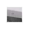
도 1a 및 도 1b는 PMOS 트랜지스터의 게이트를 형성하기 위하여 증착된 폴리실리콘막을 플라즈마 도핑 방법으로 도핑하기 전, 후의 폴리실리콘막의 두께를 비교하기 위하여 나타낸 TEM 사진이다.1A and 1B are TEM photographs shown for comparing the thicknesses of polysilicon films before and after doping a polysilicon film deposited to form a gate of a PMOS transistor by a plasma doping method.
도 1a의 경우 폴리실리콘막을 도핑하기 전의 TEM 사진으로, 910Å 두께의 폴리실리콘막이 증착되어 있다.In the case of FIG. 1A, a polysilicon film having a thickness of 910 Å is deposited as a TEM photograph before the polysilicon film is doped.
도 1b의 경우, 910Å의 두께로 증착된 폴리실리콘막을 플라즈마 도핑 방법을 사용하여 보론(B) 이온을 7.0 × 10¹⁶개/㎤의 농도로 도핑한 후의 TEM 사진으로, 폴리실리콘막의 두께가 980Å으로 측정되었다. 즉, 플라즈마 도핑 방법으로 폴리실리콘막을 도핑하는 과정에서 70Å의 실리콘-보론 화합물(SiBX) 또는 산화막이 형성되었음을 알 수 있다.In the case of Figure 1b, a polysilicon film deposited to a thickness of 910kPa is a TEM photograph after doping boron (B) ions to a concentration of 7.0 × 10¹⁶ / cm3 using a plasma doping method, the thickness of the polysilicon film Was measured. That is, it can be seen that the silicon-boron compound (SiBX ) or the oxide film of 70 Å was formed during the doping of the polysilicon film by the plasma doping method.
이렇게 폴리실리콘막과 텅스텐막 사이에 형성된 산화막은 링 오실레이터 딜레이(ring oscillator delay)를 유발하게 된다. 또한, 플라즈마 도핑 방법의 경우 고가의 플라즈마 도핑장비를 신규로 구매해야 하는 어려움도 있다.The oxide film formed between the polysilicon film and the tungsten film induces a ring oscillator delay. In addition, in the case of the plasma doping method, there is a difficulty in purchasing a new expensive plasma doping equipment.
본 발명이 이루고자 하는 기술적 과제는 장비를 신규로 구매해야 하는 어려움이 없이 기존의 장비를 활용하여 폴리실리콘막을 효과적으로 도핑시킬 수 있는 PMOS 트랜지스터의 제조방법 및 이를 이용한 듀얼 게이트 형성방법을 제공하는 데 있다.The technical problem to be achieved by the present invention is to provide a method of manufacturing a PMOS transistor that can effectively doped a polysilicon film using existing equipment without difficulty to purchase new equipment and a method of forming a dual gate using the same.
상기 기술적 과제를 이루기 위하여 본 발명에 따른 PMOS 트랜지스터의 제조방법은, 반도체기판 상에 게이트절연막을 형성하는 단계와, 게이트절연막 상에 폴리실리콘막을 형성하는 단계, 및 원자층증착(ALD) 및 화학기상증착(CVD) 챔버 중의 어느 하나에서 보론(B) 함유 가스를 이용하여 폴리실리콘막을 도핑시키는 단계를 포함하는 것을 특징으로 한다.In order to achieve the above technical problem, a method of manufacturing a PMOS transistor according to the present invention includes forming a gate insulating film on a semiconductor substrate, forming a polysilicon film on the gate insulating film, and atomic layer deposition (ALD) and chemical vapor phase. Doping the polysilicon film using boron (B) containing gas in any one of the deposition (CVD) chambers.
상기 폴리실리콘막을 도핑시키는 단계에서, 상기 챔버 내의 온도는 50 ∼ 450℃인 것이 바람직하다.In the step of doping the polysilicon film, the temperature in the chamber is preferably 50 ~ 450 ℃.
상기 폴리실리콘막을 도핑시키는 단계는 10 ∼ 180초 동안 진행할 수 있다.Doping the polysilicon film may be performed for 10 to 180 seconds.
상기 폴리실리콘막을 도핑시키는 단계에서, 상기 보론(B) 함유 가스의 유량은 50 ∼ 400sccm인 것이 바람직하다.In the doping of the polysilicon film, the flow rate of the boron (B) -containing gas is preferably 50 to 400 sccm.
상기 폴리실리콘막을 도핑시키는 단계에서, 상기 보론(B) 함유가스로 B2H6 가스를 사용할 수 있다.In the doping of the polysilicon layer, B2 H6 gas may be used as the boron (B) -containing gas.
상기 다른 기술적 과제를 이루기 위하여 본 발명에 따른 반도체 소자의 듀얼 게이트 형성방법은, 반도체기판 상에 게이트절연막을 형성하는 단계와, 게이트절연막 상에 N형으로 도핑된 폴리실리콘막을 형성하는 단계와, 폴리실리콘막 상에, PMOS 영역을 노출시키는 포토레지스트 패턴을 형성하는 단계와, 원자층증착(ALD) 및 화학기상증착(CVD) 챔버 중의 어느 하나에서 보론(B) 함유 가스를 이용하여 PMOS 영역의 폴리실리콘막을 P형으로 도핑시키는 단계와, 포토레지스트 패턴을 제거한 후 폴리실리콘막 상에 금속전극막을 형성하는 단계와, 금속전극막 상에 NMOS 및 PMOS 게이트가 형성될 영역을 한정하는 하드마스크를 형성하는 단계와, 하드마스크를 이용하여 금속전극막, 폴리실리콘막 및 게이트절연막을 패터닝하여 NMOS 및 PMOS 트랜지스터의 게이트를 각각 형성하는 단계를 포함하는 것을 특징으로 한다.According to another aspect of the present invention, there is provided a method of forming a dual gate of a semiconductor device, the method comprising: forming a gate insulating film on a semiconductor substrate, forming an N-type doped polysilicon film on the gate insulating film, and Forming a photoresist pattern exposing the PMOS region on the silicon film, and using a boron (B) containing gas in one of the atomic layer deposition (ALD) and chemical vapor deposition (CVD) chambers to Doping the silicon film into a P-type, forming a metal electrode film on the polysilicon film after removing the photoresist pattern, and forming a hard mask on the metal electrode film to define a region where NMOS and PMOS gates are to be formed. And patterning the metal electrode film, the polysilicon film, and the gate insulating film by using a hard mask to respectively gate the gates of the NMOS and PMOS transistors. It characterized by comprising the step of forming.
상기 PMOS 영역의 폴리실리콘막을 P형으로 도핑시키는 단계에서, 상기 챔버 내의 온도는 50 ∼ 450℃인 것이 바람직하다.In the step of doping the polysilicon film of the PMOS region to the P-type, the temperature in the chamber is preferably 50 ~ 450 ℃.
상기 PMOS 영역의 폴리실리콘막을 P형으로 도핑시키는 단계는, 10 ∼ 180초 동안 진행할 수 있다.Doping the polysilicon film of the PMOS region into a P-type may be performed for 10 to 180 seconds.
상기 PMOS 영역의 폴리실리콘막을 P형으로 도핑시키는 단계에서, 상기 보론(B) 함유 가스의 유량은 50 ∼ 400sccm인 것이 바람직하다.In the step of doping the polysilicon film in the PMOS region to P-type, the flow rate of the boron (B) -containing gas is preferably 50 to 400sccm.
상기 PMOS 영역의 폴리실리콘막을 P형으로 도핑시키는 단계에서, 상기 보론(B) 함유가스로 B2H6 가스를 사용할 수 있다.In the step of doping the polysilicon film of the PMOS region to the P-type, B2 H6 gas may be used as the boron (B) containing gas.
상기 NMOS 및 PMOS 트랜지스터의 게이트를 각각 형성하는 단계 후에, NMOS 및 PMOS 트랜지스터의 게이트의 측벽에 절연막 스페이서를 형성하는 단계를 더 포함할 수 있다.After forming the gates of the NMOS and PMOS transistors, the method may further include forming insulating layer spacers on sidewalls of the gates of the NMOS and PMOS transistors.
본 발명에 의한 PMOS 트랜지스터 제조방법 및 듀얼 게이트 형성방법에 따르면, 폴리실리콘막 표면에 보론(B) 이온이 쌓이는 현상을 방지할 수 있으며, 폴리실리콘막과 금속전극막 사이에 산화막이 형성되는 것을 방지할 수 있다. 또한, 반도체 제조공정에 많이 사용되고 있는 ALD 장비 또는 CVD 장비를 이용함으로써 플라즈마 도핑장비의 추가 구매에 따른 비용을 절감할 수 있다.According to the PMOS transistor manufacturing method and the dual gate formation method according to the present invention, it is possible to prevent the accumulation of boron (B) ions on the surface of the polysilicon film, and to prevent the formation of an oxide film between the polysilicon film and the metal electrode film. can do. In addition, by using ALD equipment or CVD equipment which is widely used in the semiconductor manufacturing process, it is possible to reduce the cost of additional purchase of plasma doping equipment.
이하, 첨부된 도면을 참조하여 본 발명의 바람직한 실시예를 상세히 설명하기로 한다. 그러나, 본 발명의 실시예들은 여러 가지 다른 형태로 변형될 수 있으며, 본 발명의 범위가 아래에서 상술하는 실시예들로 인해 한정되는 것으로 해석되어서는 안된다.Hereinafter, exemplary embodiments of the present invention will be described in detail with reference to the accompanying drawings. However, embodiments of the present invention may be modified in many different forms, and the scope of the present invention should not be construed as being limited by the embodiments described below.
도 2는 플라즈마 도핑 방법을 이용하여 보론(B) 이온을 도핑한 폴리실리콘막의 SIMS 프로파일을 나타낸 도면으로, 11B 이온을 각각 5.0 × 10¹⁵개/㎤, 6.0 × 10¹⁵개/㎤ 및 7.0 × 10¹⁵개/㎤의 농도로 주입한 경우의 폴리실리콘막의 깊이에 따른 도핑 프로파일을 나타낸다. 플라즈마 도핑 방법을 사용한 세 경우 모두 보론 이온이 600Å 정도 깊이까지 도달한 것을 알 수 있다.FIG. 2 is a view showing a SIMS profile of a polysilicon film doped with boron (B) ions using a plasma doping method, in which 11B ions are 5.0 × 10¹⁵ pieces / cm 3, 6.0 × 10¹⁵ pieces / cm 3, and 7.0 × 10, respectively.The doping profile according to the depth of the polysilicon film when injected at a concentration of15 pieces / cm 3 is shown. In all three cases using the plasma doping method, it can be seen that boron ions have reached a depth of about 600 kPa.
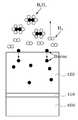
도 3은 원자층 증착(ALD) 장비 및 화학기상증착(CVD) 장비를 이용하여 보 론(B) 이온을 도핑한 폴리실리콘막의 SIMS 프로파일을 나타낸 도면이다.3 is a view showing a SIMS profile of a polysilicon film doped with boron (B) ions using atomic layer deposition (ALD) equipment and chemical vapor deposition (CVD) equipment.
도면 참조번호 "210"은 베어(bare) 웨이퍼에 도핑하는 경우, "220"은 원자층증착(ALD) 장비에서 B2H6 가스를 이용하여 295℃의 온도에서 60초간 소킹(soaking)한 경우, 그리고 "230"은 화학기상증착(CVD) 장비의 일종인 ANL(Advanced Neucleation Layer) 장비에서 B2H6가스를 이용하여 375℃의 온도에서 60초간 소킹(soaking)한 경우를 각각 나타낸다.In the drawing, reference numeral “210” refers to doping a bare wafer, and “220” refers to soaking for 60 seconds at a temperature of 295 ° C. using B2 H6 gas in an atomic layer deposition (ALD) device. And, "230" represents the case of soaking for 60 seconds at a temperature of 375 ℃ using B2 H6 gas in the Advanced Neucleation Layer (ALN) equipment, which is a kind of chemical vapor deposition (CVD) equipment.
도시된 바와 같이, 1 × 10¹⁸개/㎤의 농도를 나타내는 도펀트의 도달깊이가 320Å으로, 도 2에 도시된 플라즈마 도핑의 경우에 비해 280Å이 감소한 것을 알 수 있다. 이와 같이 도펀트의 도달 깊이가 감소한 것은 이후 열공정에서 보론(B) 이온이 게이트산화막을 뚫고 확산될 가능성이 플라즈마 도핑의 경우에 비해 낮다는 것을 의미한다.As shown, it can be seen that the reaching depth of the dopant having a concentration of 1 × 10¹⁸ atoms / cm 3 is 320 kPa, which is reduced by 280 kPa compared with the case of plasma doping shown in FIG. 2. This reduction in the depth of arrival of the dopant means that the possibility of diffusion of boron (B) ions through the gate oxide film in the subsequent thermal process is lower than in the case of plasma doping.
본 발명은 원자층증착 또는 화학기상증착 챔버에서 B2H6 가스 소킹(soaking)을 이용하여 보론(B)을 폴리실리콘막 내부로 도핑시키는 방법으로 PMOS 트랜지스터의 게이트 및 듀얼 게이트를 형성하는 방법을 제시한다.The present invention relates to a method of forming a gate and a dual gate of a PMOS transistor by doping boron (B) into a polysilicon layer using B2 H6 gas soaking in an atomic layer deposition or chemical vapor deposition chamber. present.
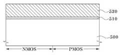
도 4는 본 발명에 따른 PMOS 트랜지스터의 제조방법을 설명하기 위하여 도시한 단면도이고, 도 5 및 도 6은 B2H6 가스를 이용하여 폴리실리콘막을 도핑하는 메카니즘을 설명하기 위하여 도시한 단면도들이다.4 is a cross-sectional view illustrating a method of manufacturing a PMOS transistor according to the present invention, and FIGS. 5 and 6 are cross-sectional views illustrating a mechanism of doping a polysilicon film using B2 H6 gas.
도 4를 참조하면, 반도체기판(400)에 게이트절연막(410)을 형성한다. 상기 반도체기판(400)은 예를 들면 P형 실리콘기판일 수 있다. 게이트절연막(410)은 반도체기판의 표면을 산화시켜 형성하거나, 산화막, 질화막 또는 산질화막(SiON)을 화학기상증착(CVD) 방법으로 증착하여 형성하거나, 산화막/질화막/산화막을 차례로 적층하여 ONO 구조로 형성할 수 있다.Referring to FIG. 4, a
게이트절연막(410) 상에 폴리실리콘막(420)을 일정 두께 증착하여 게이트도전막을 형성한다. 다음, PMOS 트랜지스터의 게이트를 형성하기 위하여 상기 폴리실리콘막(420)을 P형 도펀트로 도핑한다. 구체적으로, 폴리실리콘막(420)이 형성된 반도체기판을 원자층증착(ALD) 챔버 또는 화학기상증착(CVD) 챔버로 로딩한 다음, 핵생성 가스로, B2H6 가스와 같은 보론(B)을 함유하는 가스를 챔버 내부로 주입하여 폴리실리콘막(420)을 소킹(soaking)한다. 이때, ALD 또는 CVD 챔버의 온도는 50 ∼ 450℃ 정도, 소킹시간은 10 ∼ 180초 정도, 그리고 B2H6 가스의 유량은 50 ∼ 400sccm 정도로 한다.A
폴리실리콘막(420)이 형성된 반도체기판을 ALD 챔버로 로딩한 후 상기한 조건에서 B2H6 가스를 챔버 내부로 주입하면, 도 5 및 도 6에 도시된 바와 같이, 열 에너지에 의해 B2H6 가스가 보론(B) 원자와 수소가스(H2)로 분해된다. 이때 분해된 수소가스(H2)는 휘발되고 보론(B) 원자는 열 에너지에 의해 폴리실리콘막(420) 내부로 확산되어 들어감으로써 폴리실리콘막(420)이 보론(B)으로 도핑된다.After loading the semiconductor substrate on which the
도 7a 내지 도 7c는 ALD 또는 CVD 방식을 이용하여 폴리실리콘막에 보론(B) 을 도핑하기 전 후의 TEM 사진들로서, 도 7a는 폴리실리콘막을 보론(B)으로 도핑하기 전의 TEM 사진이고, 도 7b는 ALD 챔버에서 B2H6 가스로 소킹한 경우의 TEM 사진이며, 도 7c는 CVD 챔버에서 B2H6 가스로 소킹한 경우의 TEM 사진이다.7A to 7C are TEM photographs before and after doping the boron (B) to the polysilicon film using the ALD or CVD method, Figure 7a is a TEM image before doping the polysilicon film with boron (B), Figure 7b Is a TEM photograph when soaked with B2 H6 gas in an ALD chamber, and FIG. 7C is a TEM photograph when soaked with B2 H6 gas in a CVD chamber.
도 7b 및 도 7c에 도시된 바와 같이, 폴리실리콘막의 표면에 실리콘(Si)-보론(B) 화합물(SiBX)의 적층없이 폴리실리콘막이 도핑된 것을 알 수 있다. 폴리실리콘막의 표면에 실리콘-보론 화합물(SiBX)이 적층되지 않았다는 것은 후속 세정 또는 포토레지스트 스트립 공정에서 실리콘-보론 화합물(SiBX)이 제거되면서 폴리실리콘막 표면에서 보론(B)의 손실이 일어나지 않는다는 것을 의미한다.As shown in FIGS. 7B and 7C, it can be seen that the polysilicon layer is doped without the deposition of silicon (Si) -boron (B) compound (SiBX ) on the surface of the polysilicon layer. It has not been laminated boron compound (SiBX) of silicon in the subsequent cleaning or photoresist strip step-poly silicon film, the surface of the silicon not cause a loss of boron (B) in the polysilicon film surface as the boron compound (SiBX) is removed, It means not.
다음에, 본 발명에 따른 반도체소자의 듀얼 게이트 형성방법을 설명하기로 한다.Next, a dual gate forming method of a semiconductor device according to the present invention will be described.
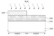
도 8 내지 도 10은 본 발명에 따른 반도체소자의 듀얼 게이트 형성방법을 설명하기 위하여 도시한 단면도들이다.8 to 10 are cross-sectional views illustrating a method of forming a dual gate of a semiconductor device according to the present invention.
도 8을 참조하면, 반도체기판(500)에 활성영역과 비활성영역을 한정하기 위한 소자분리막(도시되지 않음)을 통상적인 방법으로 형성한다. 이온주입 및 열처리 공정을 통해 반도체기판(500)에 웰(도시되지 않음)을 형성한다. 다음, 상기 반도체기판(500) 상에 예를 들어 산화막을 성장시켜 게이트절연막(510)을 형성한다. 게이트절연막(510)은 실리콘산화막(SiO2)로 형성하거나, 또는 하프늄옥사이드(HfO)와 같은 고유전막(high-k dielectric layer)으로 형성할 수도 있다.Referring to FIG. 8, an isolation layer (not shown) for defining an active region and an inactive region is formed on a
다음, 게이트전극 형성을 위한 폴리실리콘막(520)을 증착한다. 폴리실리콘막(520)은 도핑된 폴리실리콘막 또는 도핑되지 않은 폴리실리콘막으로 형성할 수 있다. 본 발명의 경우 N형으로 도핑된 폴리실리콘막을 형성하였다. 폴리실리콘막(520)의 두께는 소자의 종류에 따라 다른데, 예를 들어 44nm급 DRAM의 트랜지스터인 경우 500 ∼ 800Å 정도의 두께로 형성할 수 있다.Next, a
도 9를 참조하면, 통상, 양산에서는 공정의 단순화를 위하여 마스크 작업을 한 번만 실시하여 PMOS 및 NMOS 게이트를 형성하기 위하여 전체적으로 N형으로 도핑된 폴리실리콘막을 형성한 후 PMOS 영역을 P형 도펀트로 카운트 도핑시키는 방법을 사용한다. 상기 폴리실리콘막이 도핑되지 않은 경우, N형의 도펀트를 전체적으로 주입하여 폴리실리콘막을 N형으로 도핑시킨다. 다음에, N형으로 도핑된 상기 폴리실리콘막(520) 위에 P형 게이트전극이 형성될 영역을 한정하는 포토레지스트 패턴(530)을 형성한다. 포토레지스트 패턴(530)은 PMOS 트랜지스터가 형성될 영역은 노출시키고 NMOS 트랜지스터가 형성될 영역을 가리는 모양으로 형성된다.Referring to FIG. 9, in general, in mass production, a mask operation is performed only once to form a PMOS and an NMOS gate to form a polysilicon film doped entirely with N-type to form a PMOS and NMOS gate, and then count the PMOS region with a P-type dopant. Doping method is used. When the polysilicon film is not doped, the polysilicon film is doped into the N-type by injecting the N-type dopant as a whole. Next, a
다음에, 포토레지스트 패턴(530)을 마스크로 하여 PMOS 영역의 폴리실리콘막을 P형 도펀트로 도핑시킨다. 구체적으로, 폴리실리콘막(520) 및 포토레지스트 패턴(530)이 형성된 반도체기판을 원자층증착(ALD) 챔버 또는 화학기상증착(CVD) 챔버로 로딩한 다음, 보론(B)을 함유하는 가스, 예를 들어 B2H6 가스를 챔버 내부로 주입하여 PMOS 영역의 폴리실리콘막(520)을 소킹(soaking)한다. 이때, ALD 또는 CVD 챔버의 온도는 50 ∼ 450℃ 정도, 소킹시간은 10 ∼ 180초 정도, 그리고 B2H6 가스의 유량은 50 ∼ 400sccm 정도로 한다.Next, the polysilicon film in the PMOS region is doped with a P-type dopant using the
도 10을 참조하면, 상기 포토레지스트 패턴을 제거한 후, 전체 게이트영역에서 불순물의 확산이 충분히 이루어지도록 하기 위하여 소정 온도에서 반도체기판을 열처리한다. 이 열처리공정에서 상기 폴리실리콘막의 결정화가 이루어진다.Referring to FIG. 10, after removing the photoresist pattern, the semiconductor substrate is heat-treated at a predetermined temperature to sufficiently diffuse impurities in the entire gate region. In this heat treatment step, the polysilicon film is crystallized.
다음에, 상기 폴리실리콘막(521, 522)에 형성된 자연산화막을 제거하기 위한 세정공정을 실시한다. 이어서 상기 폴리실리콘막 위에 텅스텐(W) 또는 텅스텐 실리사이드(WSi)를 증착하여 금속 전극막(541, 542)을 형성하고, 그 위에 질화막을 증착한 다음 패터닝하여 하드마스크층(551, 552)을 형성한다. 상기 하드마스크층(551, 552)을 마스크로 하여 상기 금속 전극막(541, 542)과 폴리실리콘막(521, 522)을 차례로 패터닝하여 NMOS 영역 및 PMOS 영역에 각각 게이트 패턴을 형성한다. 이어서, 게이트 패턴의 측면에 절연막 스페이서(561, 562)를 형성한다. 절연막 스페이서(56, 562)는 게이트 패턴이 형성된 결과물 상에 예를 들면 산화막 또는 질화막을 증착한 후 에치백하여 형성할 수 있다.Next, a cleaning process for removing the natural oxide film formed on the
이상 설명한 바와 같이, 본 발명의 PMOS 트랜지스터 및 듀얼 게이트 형성방법에서는 이온주입 또는 플라즈마 도핑 방법 대신에 원자층증착(ALD) 또는 화학기상증착(CVD) 챔버에서 보론을 함유하는 가스와 열 에너지를 이용하여 소킹(soaking)하는 방법으로 폴리실리콘막을 도핑시킨다. 본 발명에 따르면, 폴리실리콘막 표면에 보론(B) 이온이 쌓이는 현상을 방지할 수 있으며, 폴리실리콘막과 텅스텐막 사이에 산화막이 형성되는 것을 방지할 수 있다. 또한, 반도체 제조공정에 많이 사용되고 있는 ALD 장비 또는 CVD 장비를 이용함으로써 플라즈마 도핑장비 의 추가 구매에 따른 비용을 절감할 수 있다.As described above, in the PMOS transistor and the dual gate forming method of the present invention, the boron-containing gas and thermal energy are used in an atomic layer deposition (ALD) or chemical vapor deposition (CVD) chamber instead of the ion implantation or plasma doping method. The polysilicon film is doped by soaking. According to the present invention, a phenomenon in which boron (B) ions are accumulated on the surface of the polysilicon film can be prevented, and an oxide film can be prevented from being formed between the polysilicon film and the tungsten film. In addition, by using ALD equipment or CVD equipment which is widely used in the semiconductor manufacturing process, it is possible to reduce the cost of additional purchase of plasma doping equipment.
이상 본 발명을 바람직한 실시예를 들어 상세하게 설명하였으나, 본 발명은 상기 실시예에 한정되지 않으며, 본 발명의 기술적 사상 내에서 당 분야에서 통상의 지식을 가진 자에 의하여 여러 가지 변형이 가능함은 당연하다.Although the present invention has been described in detail with reference to preferred embodiments, the present invention is not limited to the above embodiments, and various modifications may be made by those skilled in the art within the technical spirit of the present invention. Do.
도 1a 및 도 1b는 폴리실리콘막을 플라즈마 도핑 방법으로 도핑하기 전, 후의 폴리실리콘막의 두께를 비교하기 위하여 나타낸 TEM 사진이다.1A and 1B are TEM photographs shown to compare thicknesses of a polysilicon film before and after doping the polysilicon film by a plasma doping method.
도 2는 플라즈마 도핑 방법을 이용하여 보론(B) 이온을 도핑한 폴리실리콘막의 SIMS 프로파일을 나타낸 도면이다.2 is a diagram showing a SIMS profile of a polysilicon film doped with boron (B) ions using a plasma doping method.
도 3은 원자층 증착(ALD) 장비 및 화학기상증착(CVD) 장비를 이용하여 보론(B) 이온을 도핑한 폴리실리콘막의 SIMS 프로파일을 나타낸 도면이다.3 is a view showing a SIMS profile of a polysilicon film doped with boron (B) ions using atomic layer deposition (ALD) equipment and chemical vapor deposition (CVD) equipment.
도 4는 본 발명에 따른 PMOS 트랜지스터의 제조방법을 설명하기 위하여 도시한 단면도이다.4 is a cross-sectional view illustrating a method of manufacturing a PMOS transistor according to the present invention.
도 5 및 도 6은 B2H6 가스를 이용하여 폴리실리콘막을 도핑하는 메카니즘을 설명하기 위하여 도시한 단면도들이다.5 and 6 are cross-sectional views illustrating a mechanism for doping a polysilicon film using B2 H6 gas.
도 7a 내지 도 7c는 ALD 또는 CVD 방식을 이용하여 폴리실리콘막에 보론(B)을 도핑하기 전 후의 TEM 사진들이다.7A to 7C are TEM photographs before and after doping boron (B) to a polysilicon film using an ALD or CVD method.
도 8 내지 도 10은 본 발명에 따른 반도체소자의 듀얼 게이트 형성방법을 설명하기 위하여 도시한 단면도들이다.8 to 10 are cross-sectional views illustrating a method of forming a dual gate of a semiconductor device according to the present invention.
Claims (11)
Translated fromKoreanPriority Applications (2)
| Application Number | Priority Date | Filing Date | Title |
|---|---|---|---|
| KR1020080111581AKR101057188B1 (en) | 2008-11-11 | 2008-11-11 | Method for manufacturing PMOS transistor and method for forming dual gate of semiconductor device using same |
| US12/346,492US7935591B2 (en) | 2008-11-11 | 2008-12-30 | Method for fabricating PMOS transistor and method for forming dual gate using the same |
Applications Claiming Priority (1)
| Application Number | Priority Date | Filing Date | Title |
|---|---|---|---|
| KR1020080111581AKR101057188B1 (en) | 2008-11-11 | 2008-11-11 | Method for manufacturing PMOS transistor and method for forming dual gate of semiconductor device using same |
Publications (2)
| Publication Number | Publication Date |
|---|---|
| KR20100052741A KR20100052741A (en) | 2010-05-20 |
| KR101057188B1true KR101057188B1 (en) | 2011-08-16 |
Family
ID=42165601
Family Applications (1)
| Application Number | Title | Priority Date | Filing Date |
|---|---|---|---|
| KR1020080111581AExpired - Fee RelatedKR101057188B1 (en) | 2008-11-11 | 2008-11-11 | Method for manufacturing PMOS transistor and method for forming dual gate of semiconductor device using same |
Country Status (2)
| Country | Link |
|---|---|
| US (1) | US7935591B2 (en) |
| KR (1) | KR101057188B1 (en) |
Families Citing this family (9)
| Publication number | Priority date | Publication date | Assignee | Title |
|---|---|---|---|---|
| KR101185987B1 (en)* | 2009-06-15 | 2012-09-25 | 에스케이하이닉스 주식회사 | Method of doping p-type impurity ions in dual poly gate and forming the dual poly gate using the same |
| US8569158B2 (en) | 2011-03-31 | 2013-10-29 | Tokyo Electron Limited | Method for forming ultra-shallow doping regions by solid phase diffusion |
| US8580664B2 (en)* | 2011-03-31 | 2013-11-12 | Tokyo Electron Limited | Method for forming ultra-shallow boron doping regions by solid phase diffusion |
| CN103579317A (en)* | 2012-08-10 | 2014-02-12 | 上海华虹Nec电子有限公司 | Gate structure and manufacturing method |
| JP2014192485A (en) | 2013-03-28 | 2014-10-06 | Hitachi Kokusai Electric Inc | Semiconductor device manufacturing method, substrate processing method and substrate processing apparatus |
| US9899224B2 (en) | 2015-03-03 | 2018-02-20 | Tokyo Electron Limited | Method of controlling solid phase diffusion of boron dopants to form ultra-shallow doping regions |
| CN110391185B (en)* | 2018-04-17 | 2021-08-03 | 联华电子股份有限公司 | Method of making semiconductor element |
| WO2020131392A1 (en)* | 2018-12-20 | 2020-06-25 | Applied Materials, Inc. | Method of growing doped group iv materials |
| US11798808B1 (en)* | 2020-07-22 | 2023-10-24 | National Technology & Engineering Solutions Of Sandia, Llc | Method of chemical doping that uses CMOS-compatible processes |
Family Cites Families (3)
| Publication number | Priority date | Publication date | Assignee | Title |
|---|---|---|---|---|
| JP2920546B2 (en)* | 1989-12-06 | 1999-07-19 | セイコーインスツルメンツ株式会社 | Method for manufacturing same-polarity gate MIS transistor |
| US5897363A (en) | 1996-05-29 | 1999-04-27 | Micron Technology, Inc. | Shallow junction formation using multiple implant sources |
| KR100568859B1 (en) | 2003-08-21 | 2006-04-10 | 삼성전자주식회사 | Method for manufacturing transistor of DRAM semiconductor device |
- 2008
- 2008-11-11KRKR1020080111581Apatent/KR101057188B1/ennot_activeExpired - Fee Related
- 2008-12-30USUS12/346,492patent/US7935591B2/enactiveActive
Also Published As
| Publication number | Publication date |
|---|---|
| US7935591B2 (en) | 2011-05-03 |
| US20100120240A1 (en) | 2010-05-13 |
| KR20100052741A (en) | 2010-05-20 |
Similar Documents
| Publication | Publication Date | Title |
|---|---|---|
| KR101057188B1 (en) | Method for manufacturing PMOS transistor and method for forming dual gate of semiconductor device using same | |
| JP4791332B2 (en) | Semiconductor structure including double metal gate and manufacturing method thereof (self-alignment integration of double metal gate) | |
| KR100618815B1 (en) | Semiconductor device having heterogeneous gate insulating film and manufacturing method thereof | |
| KR100951227B1 (en) | Selective Implementation of Barrier Layers for Controlling Threshold Voltages in CMOS Devices with High-K dielectrics | |
| KR20010060567A (en) | Method of forming a gate dielectric film in a semiconductor device | |
| JP2002198526A (en) | Method for manufacturing semiconductor device | |
| US7939396B2 (en) | Base oxide engineering for high-K gate stacks | |
| KR100843223B1 (en) | Semiconductor device adopting heterogeneous metal gate structure according to channel type and its manufacturing method | |
| WO2004107451A1 (en) | Semiconductor device fitted with mis type field-effect transistor, process for producing the same and method of forming metal oxide film | |
| CN101356639B (en) | Semiconductor device and its manufacturing process | |
| KR100821089B1 (en) | Semiconductor device and manufacturing method thereof | |
| KR101212567B1 (en) | Semiconductor device and method for manufacturing threof | |
| KR20110135086A (en) | Semiconductor device and manufacturing method thereof | |
| KR100968412B1 (en) | Gate stack and its manufacturing method | |
| KR20120089147A (en) | Manufacturing method of semiconductor device | |
| US7244642B2 (en) | Method to obtain fully silicided gate electrodes | |
| KR101062835B1 (en) | Method for manufacturing gate electrode of semiconductor device using double hard mask | |
| KR100712523B1 (en) | Semiconductor device having heterogeneous gate insulating film and manufacturing method thereof | |
| KR100703835B1 (en) | A semiconductor device having a dual polysilicon gate having a polysilicon depletion phenomenon and a manufacturing method thereof | |
| JP5141321B2 (en) | Manufacturing method of semiconductor device | |
| KR100920038B1 (en) | Gate of semiconductor device and forming method thereof | |
| KR20060037776A (en) | Method for manufacturing a semiconductor device having a gate spacer by atomic layer deposition | |
| KR20020049350A (en) | Method of manufacturing a semiconductor device | |
| KR20080018711A (en) | Semiconductor device and manufacturing method thereof | |
| KR20100019826A (en) | Method for fabricating nonvolatile memory device |
Legal Events
| Date | Code | Title | Description |
|---|---|---|---|
| A201 | Request for examination | ||
| PA0109 | Patent application | St.27 status event code:A-0-1-A10-A12-nap-PA0109 | |
| PA0201 | Request for examination | St.27 status event code:A-1-2-D10-D11-exm-PA0201 | |
| PG1501 | Laying open of application | St.27 status event code:A-1-1-Q10-Q12-nap-PG1501 | |
| D13-X000 | Search requested | St.27 status event code:A-1-2-D10-D13-srh-X000 | |
| D14-X000 | Search report completed | St.27 status event code:A-1-2-D10-D14-srh-X000 | |
| E902 | Notification of reason for refusal | ||
| PE0902 | Notice of grounds for rejection | St.27 status event code:A-1-2-D10-D21-exm-PE0902 | |
| E13-X000 | Pre-grant limitation requested | St.27 status event code:A-2-3-E10-E13-lim-X000 | |
| P11-X000 | Amendment of application requested | St.27 status event code:A-2-2-P10-P11-nap-X000 | |
| P13-X000 | Application amended | St.27 status event code:A-2-2-P10-P13-nap-X000 | |
| E701 | Decision to grant or registration of patent right | ||
| PE0701 | Decision of registration | St.27 status event code:A-1-2-D10-D22-exm-PE0701 | |
| GRNT | Written decision to grant | ||
| PR0701 | Registration of establishment | St.27 status event code:A-2-4-F10-F11-exm-PR0701 | |
| PR1002 | Payment of registration fee | St.27 status event code:A-2-2-U10-U11-oth-PR1002 Fee payment year number:1 | |
| PG1601 | Publication of registration | St.27 status event code:A-4-4-Q10-Q13-nap-PG1601 | |
| PN2301 | Change of applicant | St.27 status event code:A-5-5-R10-R13-asn-PN2301 St.27 status event code:A-5-5-R10-R11-asn-PN2301 | |
| PN2301 | Change of applicant | St.27 status event code:A-5-5-R10-R13-asn-PN2301 St.27 status event code:A-5-5-R10-R11-asn-PN2301 | |
| FPAY | Annual fee payment | Payment date:20140723 Year of fee payment:4 | |
| PR1001 | Payment of annual fee | St.27 status event code:A-4-4-U10-U11-oth-PR1001 Fee payment year number:4 | |
| PN2301 | Change of applicant | St.27 status event code:A-5-5-R10-R13-asn-PN2301 St.27 status event code:A-5-5-R10-R11-asn-PN2301 | |
| FPAY | Annual fee payment | Payment date:20150721 Year of fee payment:5 | |
| PR1001 | Payment of annual fee | St.27 status event code:A-4-4-U10-U11-oth-PR1001 Fee payment year number:5 | |
| FPAY | Annual fee payment | Payment date:20160721 Year of fee payment:6 | |
| PR1001 | Payment of annual fee | St.27 status event code:A-4-4-U10-U11-oth-PR1001 Fee payment year number:6 | |
| FPAY | Annual fee payment | Payment date:20170724 Year of fee payment:7 | |
| PR1001 | Payment of annual fee | St.27 status event code:A-4-4-U10-U11-oth-PR1001 Fee payment year number:7 | |
| FPAY | Annual fee payment | Payment date:20180725 Year of fee payment:8 | |
| PR1001 | Payment of annual fee | St.27 status event code:A-4-4-U10-U11-oth-PR1001 Fee payment year number:8 | |
| PC1903 | Unpaid annual fee | St.27 status event code:A-4-4-U10-U13-oth-PC1903 Not in force date:20190810 Payment event data comment text:Termination Category : DEFAULT_OF_REGISTRATION_FEE | |
| PC1903 | Unpaid annual fee | St.27 status event code:N-4-6-H10-H13-oth-PC1903 Ip right cessation event data comment text:Termination Category : DEFAULT_OF_REGISTRATION_FEE Not in force date:20190810 | |
| P22-X000 | Classification modified | St.27 status event code:A-4-4-P10-P22-nap-X000 |