KR101056881B1 - An internal combustion engine - Google Patents
An internal combustion engineDownload PDFInfo
- Publication number
- KR101056881B1 KR101056881B1KR1020097004975AKR20097004975AKR101056881B1KR 101056881 B1KR101056881 B1KR 101056881B1KR 1020097004975 AKR1020097004975 AKR 1020097004975AKR 20097004975 AKR20097004975 AKR 20097004975AKR 101056881 B1KR101056881 B1KR 101056881B1
- Authority
- KR
- South Korea
- Prior art keywords
- valve
- internal combustion
- combustion engine
- lift curve
- inlet
- Prior art date
- Legal status (The legal status is an assumption and is not a legal conclusion. Google has not performed a legal analysis and makes no representation as to the accuracy of the status listed.)
- Expired - Fee Related
Links
Images

Classifications
- F—MECHANICAL ENGINEERING; LIGHTING; HEATING; WEAPONS; BLASTING
- F01—MACHINES OR ENGINES IN GENERAL; ENGINE PLANTS IN GENERAL; STEAM ENGINES
- F01L—CYCLICALLY OPERATING VALVES FOR MACHINES OR ENGINES
- F01L13/00—Modifications of valve-gear to facilitate reversing, braking, starting, changing compression ratio, or other specific operations
- F01L13/06—Modifications of valve-gear to facilitate reversing, braking, starting, changing compression ratio, or other specific operations for braking
- F—MECHANICAL ENGINEERING; LIGHTING; HEATING; WEAPONS; BLASTING
- F02—COMBUSTION ENGINES; HOT-GAS OR COMBUSTION-PRODUCT ENGINE PLANTS
- F02D—CONTROLLING COMBUSTION ENGINES
- F02D13/00—Controlling the engine output power by varying inlet or exhaust valve operating characteristics, e.g. timing
- F02D13/02—Controlling the engine output power by varying inlet or exhaust valve operating characteristics, e.g. timing during engine operation
- F02D13/04—Controlling the engine output power by varying inlet or exhaust valve operating characteristics, e.g. timing during engine operation using engine as brake
- F—MECHANICAL ENGINEERING; LIGHTING; HEATING; WEAPONS; BLASTING
- F02—COMBUSTION ENGINES; HOT-GAS OR COMBUSTION-PRODUCT ENGINE PLANTS
- F02D—CONTROLLING COMBUSTION ENGINES
- F02D9/00—Controlling engines by throttling air or fuel-and-air induction conduits or exhaust conduits
- F02D9/08—Throttle valves specially adapted therefor; Arrangements of such valves in conduits
- Y—GENERAL TAGGING OF NEW TECHNOLOGICAL DEVELOPMENTS; GENERAL TAGGING OF CROSS-SECTIONAL TECHNOLOGIES SPANNING OVER SEVERAL SECTIONS OF THE IPC; TECHNICAL SUBJECTS COVERED BY FORMER USPC CROSS-REFERENCE ART COLLECTIONS [XRACs] AND DIGESTS
- Y02—TECHNOLOGIES OR APPLICATIONS FOR MITIGATION OR ADAPTATION AGAINST CLIMATE CHANGE
- Y02T—CLIMATE CHANGE MITIGATION TECHNOLOGIES RELATED TO TRANSPORTATION
- Y02T10/00—Road transport of goods or passengers
- Y02T10/10—Internal combustion engine [ICE] based vehicles
- Y02T10/12—Improving ICE efficiencies
Landscapes
- Engineering & Computer Science (AREA)
- Mechanical Engineering (AREA)
- General Engineering & Computer Science (AREA)
- Chemical & Material Sciences (AREA)
- Combustion & Propulsion (AREA)
- Output Control And Ontrol Of Special Type Engine (AREA)
- Exhaust-Gas Circulating Devices (AREA)
- Control Of Throttle Valves Provided In The Intake System Or In The Exhaust System (AREA)
- Supercharger (AREA)
- Valve-Gear Or Valve Arrangements (AREA)
- Valve Device For Special Equipments (AREA)
Abstract
Translated fromKoreanDescription
Translated fromKorean본 발명은 청구항 제 1 항에서 청구되는 특징에 따르는 내연 기관에 관한 것이다.The invention relates to an internal combustion engine according to the features as claimed in
AT 408 129에는 충전 내연 기관(charged internal combustion engine)이 공개되고, 상기 내연 기관의 배출 가스 터빈에는 터빈 도입 횡단면(turbine entry cross section)을 변경 가능하게 조절하기 위해 가변화 가능한 터빈 형상(turbine geometry)이 장착된다. 기관 제동 작동 중에 높은 제동력이 발생되도록, 가변화 가능한 터빈 형상이 횡단면을 감소시키는 적재 위치(stowage position)로 조절되고, 이는 높은 배출 가스 반대 압력의 증강(build-up)을 허용하며 상기 반대 압력에 대해 내연 기관의 실린더는 방출 작업(expulsion work)을 수행해야 한다. 제동력이 현재 구동 위치에서 요구되는 경우, AT 408129 B에 따라 상기 동력은 주로 엔진 제동을 통해 적용된다.AT 408 129 discloses a charged internal combustion engine, and the exhaust gas turbine of the internal combustion engine has a turbine geometry that is variable to variably adjust the turbine entry cross section. Is fitted. In order to generate a high braking force during engine braking operation, the variable turbine geometry is adjusted to a stowage position which reduces the cross section, which allows build-up of high exhaust gas counter pressures and The cylinder of the internal combustion engine must carry out expulsion work. If braking force is required at the current drive position, the power is applied primarily via engine braking according to AT 408129 B.
엔진이 작동되는 동안에, 상기 스로틀 밸브(throttle valve)는 피스톤 운동에 의해 배출 트레인(exhaust train)으로 실린더의 내용물(content)을 방출하도록 하기 위해 개방 위치로 형성된다.While the engine is running, the throttle valve is formed in an open position to allow the contents of the cylinder to be released to the exhaust train by piston motion.
본 발명의 목적은 높은 엔진 제동력(high engine braking power)이 발생되도록하며, 동시에 오랜 시간 동안 작동하는 내연 기관을 낮은 설계 비용으로 제공하는 것이다.It is an object of the present invention to provide high engine braking power and at the same time to provide an internal combustion engine that operates for a long time at a low design cost.
본 발명에 따라 상기 목적은 청구항 제 1 항의 특징에 의해 구현된다. 종속항은 유리한 실시예를 공개한다.According to the invention this object is achieved by the features of
본 발명에 따르는 내연 기관의 경우, 캠축(camshaft)에 장착된 보조 캠(auxiliary cam)이 존재하고, 상기 보조 캠은 유출밸브에 따라 작동하고 캠에 추가하여 제공되며, 상기 캠을 통해 유출밸브는 내연 기관의 규칙적인 작동으로 개방 위치로 설정된다. 상기 보조 캠을 통하여 얻을 수 있는, 유출밸브의 보조 리프트 커브(auxiliary lift curve)는 기본 리프트 커브에 대하여 상대적으로 오프셋 상태(phase-offset)이고 상기 유입 밸브의 리프트 커브와 적어도 부분적으로 가로지른다.In the case of an internal combustion engine according to the invention, there is an auxiliary cam mounted on a camshaft, the auxiliary cam operating in accordance with the outlet valve and provided in addition to the cam, through which the outlet valve is provided. Regular operation of the internal combustion engine is set to the open position. The auxiliary lift curve of the outlet valve, obtainable through the auxiliary cam, is phase-offset relative to the primary lift curve and at least partially intersects the lift curve of the inlet valve.
일반적으로 작동하는 점화 구동 모드(fired driving mode)에 있어, 일반적으로 충전 교환(charge exchange)으로 리프팅(lifting)에 추가적인 상태에 있으며, 유출밸브의 리프팅 오프(lifting-off) 및 개방(opening)은 내부 배출 가스 재순환으로써 알려진 바와 달리 일정한 정도로 수행되도록 하고, 상기 내부 배출 가스 재순환에서 개방 충전 교환 밸브에 의해 실린더를 거쳐 흡입관을 향해 배출 트레인으로부터 나오는 배출 가스의 부분적인 흐름(flow mass)이 재순환된다. 상기 배출 가스 재순환은 특히 부분적인 로드 작동(load operation)으로 수행되고 배출 가스 내 질소 산화물(nitrogen oxides, NOX)의 감소를 허용한다. 상기 내부 배출 가스 재순환은 재순환되는 배출 가스 흐름(exhaust gas mass flow)이 감소되도록 하거나 또는 적합한 경우 배출 트레인과 흡입관 사이 외부 재순환 라인으로 외부 배출 가스 재순환으로써 알려지는 바에 의해 완전히 조절되기도 한다.In a normally operated fired driving mode, it is generally in addition to lifting by charge exchange, and the lifting-off and opening of the outlet valve As is known as internal exhaust gas recirculation, it is carried out to a certain degree and in this internal exhaust gas recirculation a partial flow mass of exhaust gas exiting the exhaust train through the cylinder and towards the suction line is recycled by an open charge exchange valve. The exhaust gas recirculation is in particular carried out in a partial load operation and allows for the reduction of nitrogen oxides (NOX ) in the exhaust gas. The internal exhaust gas recirculation may be fully controlled by reducing the exhaust gas mass flow being recycled or, where appropriate, known as external exhaust gas recirculation to an external recirculation line between the discharge train and the suction line.
또 한편으로, 엔진 제동 작동에 있어, 일반적인 충전 교환에 덧붙여 추가 상기 유출밸브의 리프트(lift)는 실린더의 제어 재충전(controlled recharging)을 위해 사용되고 엔진 제동력을 증가시키기 위해 사용된다. 종래 기술에서 잘 알려진 표준 캠축과 비교하여, 본 발명에 따라 구현된 캠축은 가장 높은 엔진 제동력으로 유출밸브의 조절 메카니즘(adjustment mechanism)을 제어함에 있어 유리하다. 엔진 제동 작동에 있어 종래 기술에서 발생되는 유출밸브의 진동(oscillation)은 본 발명에 따르는 실시예의 경우 상당하게 감소된다. 상기 유출밸브는 높은 압력과 가스의 높은 흐름 속도 상태로 제어된 방식으로 안내되어, 유출밸브의 제어되지 않은 리프팅 오프(lifting-off)를 배제하고 유출밸브에 따라 작동하는 높은 로드(high load)를 수반한다. 상기 유출밸브의 추가 제어 리프팅(lifting)은 오직 보조 리프트 커브를 구현하기 위하여 상기 캠축에 보조 캠이 장착되어야 함으로 용이한 디자인 수단을 사용하여 수행될 수 있다.On the other hand, in engine braking operation, in addition to the normal filling exchange, a further lift of the outlet valve is used for controlled recharging of the cylinder and to increase the engine braking force. Compared with standard camshafts well known in the prior art, the camshafts implemented according to the invention are advantageous in controlling the adjustment mechanism of the outlet valves with the highest engine braking force. The oscillation of the outlet valve in the prior art in engine braking operation is considerably reduced for the embodiment according to the invention. The outlet valve is guided in a controlled manner at high pressure and high flow rate of gas, eliminating the uncontrolled lifting-off of the outlet valve and providing a high load acting upon the outlet valve. Entails. Further control lifting of the outlet valve can be carried out using easy design means since an auxiliary cam must be mounted on the camshaft only to implement an auxiliary lift curve.
유리한 일 실시예에 있어서, 상기 유출밸브의 보조 리프트 커브 폐쇄 운동은 적당한 시간에 유입 밸브의 리프트 커브 폐쇄 운동(closing moment) 이후 발생된다. 상기 유입 밸브 및 유출 밸브가 동시에 개방되는 경우, 지속적인 흐름 연결(continuous flow connection)은 실린더에 의해 배출 트레인(exhaust train)과 흡입관(intake tract) 사이에서 제공된다. 내부 배출 가스 재순환은 이러한 상태(phase)로 수행된다. 유출밸브의 보조 리프트 동안 유출밸브의 폐쇄 운동과 유입 밸브의 폐쇄 사이 짧은 상태(short phase)에서, 실린더 내 피스톤은 유입 행정(inlet stroke)으로부터 압축 행정(compression stroke)까지 변이(transition)로 하사점(bottom dead center)의 영역 내 위치되고, 이에 상기 실린더는 배출 트레인으로부터 배출 가스가 부분적으로 충진되고, 충진 정도(degree of filling)가 전체적으로 향상된다.In an advantageous embodiment, the secondary lift curve closing movement of the outlet valve occurs after the lift curve closing moment of the inlet valve at a suitable time. When the inlet and outlet valves are open at the same time, a continuous flow connection is provided between the exhaust train and the intake tract by the cylinder. Internal exhaust gas recirculation is carried out in this phase. In the short phase between the closing movement of the outlet valve and the closing of the inlet valve during the secondary lift of the outlet valve, the piston in the cylinder has a bottom dead center in transition from the inlet stroke to the compression stroke. Located in the area of the bottom dead center, the cylinder is partially filled with the exhaust gas from the discharge train, and the degree of filling is improved overall.
상기 유출밸브의 보조 리프트 커브 개방 지속 시간은 비록 30% 이상으로써 적절하지만, 유입 밸브의 개방 지속 시간 보다 유리하게 보다 짧으며, 일반적으로 정확히 똑 같지는 않지만 50% 이하이다. 추가적으로, 보조 리프트 커브의 리프트는 일반적으로 20% 이상은 아니지만, 유입 밸브 리프트의 10% 이상이라 하더라도 유입 밸브 리프트보다 더 작다. 보조 리프트 커브 동안 유출밸브의 짧아진 리프트와 짧아진 지속 시간은 이러한 상태로 완전히 폐쇄되는 유출밸브와 비교된 내연 기관의 규칙적인 점화 작동으로 예견되는 최소 제한으로 유도되지 않거나 또는 오직 최소 제한으로 유도된다.The auxiliary lift curve opening duration of the outlet valve is advantageously shorter than the opening duration of the inlet valve, although it is appropriate at 30% or more, and is generally 50% or less, although not exactly the same. In addition, the lift of the auxiliary lift curve is generally no more than 20%, but even smaller than the inlet valve lift, even if it is more than 10% of the inlet valve lift. The shortened lift and shortened duration of the outlet valve during the auxiliary lift curve are not induced to or are only guided to the minimum limit foreseen by the regular ignition operation of the internal combustion engine compared to the outlet valve being fully closed in this state. .
추가적인 유리한 실시예에 있어서, 상기 유출밸브와 독립적으로 작동될 수 있고 유출밸브와 같이 유출구(outlet)로부터 배출 트레인으로 개방 상태에서 방출하는 스로틀 밸브(throttle valve)로 구성되는 추가적인 충전 교환 밸브(charge exchange valve)가 제공될 수 있다. 상기 스로틀 밸브는 개별적으로 작동되는 자체의 작동기와 연결되어, 상기 스로틀 밸브는 엔진 제동 작동 중에 일정한 개방 위치가 되며 점화 작동(fired operation)에서 폐쇄된다.In a further advantageous embodiment, an additional charge exchange valve which can be operated independently of the outlet valve and consists of a throttle valve which releases in an open state from the outlet to the discharge train, such as an outlet valve. valves may be provided. The throttle valve is connected to its own individually operated actuator so that the throttle valve is in a constant open position during engine braking operation and is closed in a fired operation.
바람직하고 추가적인 일 실시예에 있어서, 상기 내연 기관은 배출 터보차저(exhaust turbocharger)가 제공되고, 상기 배출 터보차저의 교환 가스 터빈(exhaust gas turbine)은 효과적인 터빈 도입 횡단면(turbine entry cross section)을 변경가능하게 조절하기 위해 가변화 가능한 터빈 형상(variable turbine geometry)이 장착된다. 높은 엔진 제동력을 발생시키기 위해, 상기 가변화 가능한 터빈 형상이 횡단면을 감소시키는 적재 위치(stowage position)로 전달되고, 이는 실린더 유출구와 배출 가스 터빈 사이에서 실린더의 배제(expulsion of the cylinder content)를 반대하는 높은 배출 가스 반대 압력(high exhaust gas counterpressure)이 형성된다.In one preferred and further embodiment, the internal combustion engine is provided with an exhaust turbocharger, and the exhaust gas turbine of the exhaust turbocharger changes the effective turbine entry cross section. Variable turbine geometry is fitted to make the adjustment possible. In order to generate a high engine braking force, the variable turbine geometry is transferred to a stowage position which reduces the cross section, which reverses the expansion of the cylinder content between the cylinder outlet and the exhaust gas turbine. High exhaust gas counterpressure is formed.
추가적인 장정과 유리한 실시예는 추가적인 청구항으로부터 수반되는 도면의 설명으로 추론될 수 있으며, 도면은 다음과 같다.Further manual and advantageous embodiments may be deduced from the description of the figures accompanying the additional claims, which are as follows.
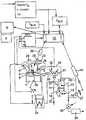
도 1은 배출 터보 차저(turbocharger)를 갖는 내연 기관의 도식적인 도면을 도시하며, 밸브의 리프트 커브(lift curve)에 영향을 주는 캠축(camshaft)과 일체로 형성된 유입 밸브 및 유출 밸브를 포함하는 내연 기관의 실린더 중 어느 한 실 린더의 확대도를 도시하는 도면.1 shows a schematic view of an internal combustion engine with an exhaust turbocharger, comprising an inlet valve and an outlet valve integrally formed with a camshaft that affects the lift curve of the valve. A diagram showing an enlarged view of one of the cylinders of an engine.
도 2는 유출 밸브를 위한 추가적인 리프트 커브의 설명을 포함하는 유입 밸브 및 유출 밸브를 위한 리프트 커브의 다이어그램을 도시하는 도면.2 shows a diagram of a lift curve for an inlet valve and an outlet valve, including a description of an additional lift curve for the outlet valve.
도 1은 예를 들어 디젤 엔진(diesel engine) 또는 스파크 점화 엔진(spark ignition engine)인 내연 기관(internal combustion engine)을 도시한다. 상기 확대 도면은 내연 기관의 실린더(1)를 도시하고, 상기 실린더의 연소 챔버(9)는 유입 밸브(5)를 통해 유입 채널(4)로 흐름이 연결되고(flow-connected) 유출 밸브(7)를 통해 배출 매니폴드(exhaust manifold, 6)로 흐름이 연결된다. 유입 채널(4)은 내연 기관의 흡입 관(intake tract, 20)과 관련되고, 반면 배출 매니폴드(exhaust manifold, 6)는 내연 기관의 배출 라인(16)과 연결된다. 유입 밸브(5)가 개방될 때 실린더(1)의 연소 챔버로 유입 채널(4)을 통하여 연소 공기(combustion air)가 흐르고, 유출 밸브(7)가 개방될 때 연소 챔버 내 위치된 가스는 배출 매니폴드(6)를 통해 배출 라인(16) 또는 배출 트레인(exhaust train)으로 방출된다.1 shows an internal combustion engine, for example a diesel engine or a spark ignition engine. The enlarged view shows a
충전 교환 밸브(charge exchange valve, 5 및 7)를 제어하기 위한 캠축(23)이 제공되고, 상기 캠축 상에 캠(cam, 24 및 25)이 장착되며, 상기 캠축의 캠(24)은 유입 밸브(inlet valve, 5)와 결합되고 캠(25)은 유출 밸브(outlet valve, 7)와 결합한다. 캠(24 및 25)의 윤곽은 적합한 트랜스미션 부재(transmission member)의 보조로 충전 교환 밸브(charge exchange valve, 5 및 7)로 전달된다. 상기 밸브(5 및 7)의 리프트 커브(lift curve)는 캠 윤곽(cam contour)에 의해 형성된다. 캠축 종 방향 축에 대한 공전(revolution) 중에, 각각의 캠 윤곽은 각각의 밸브(5, 7) 상으로 리프트 커브를 발생시키기 위해 정밀 조사되어 이동된다.Camshafts 23 are provided for controlling charge exchange valves 5 and 7,
추가적으로, 실린더(1) 상에 스로틀 밸브(28)가 장착되고, 상기 유출 밸브는 배출 라인(exhaust line, 16)으로 개방된다. 상기 스로틀 밸브(28)는 캠축(23)의 작동기(actuator, 29)를 통해 독립적으로 시동된다.In addition, a
모든 충전 교환 밸브(5, 7 및 28)는 내연 기관의 실린더 헤드(3) 내에 위치된다.All
캠(25)에 덧붙여, 또한 추가 캠이 유출 밸브(7)와 결합되거나 또는 상기 캠(25)은 추가 캠을 가지고, 상기 추가 캠을 통해 추가 리프트 커브(lift curve)가 상기 유출 밸브(7) 상으로 가압될 수 있다. 이러한 보조 리프트 커브는 도 2에서 설명되고 도 2를 참조하여 설명될 수 있다.In addition to the
도 1에서 도시될 수 있는 바와 같이, 상기 내연 기관은 배출 터보 차저(exhaust turbocharger, 2)가 장착되고, 상기 배출 터보 차저는 배출 라인(16) 내 배출 가스 터빈(exhaust gas turbine, 10)과 흡입 관(intake tract, 20) 내 압축기(compressor, 11)를 포함한다. 상기 배출 가스 터빈(10)의 터빈 휠은 샤프트(12)를 통해 압축기(11)의 압축 휠(compressor wheel)로 회전식으로 커플 결합된다. 내연 기관의 작동 중에, 상승 압력(elevated pressure)으로 압축기 휠(compressor wheel)에 의해 압축되는 연소 공기(combustion air)은 압축기 유입부(compressor entry, 19)를 통해 환경으로부터 상기 압축기(11)로 공급된다. 압축 된 상태에서, 상기 공기는 압축기 유출구(outlet, 21)를 통해 압축기로부터 발생되고(issue) 흡입 관(20)을 통해 유입 채널(4)로 제공되며, 유입 채널로 유입 이전에 적절한 경우 공기 쿨러 내 냉각 작용이 수행된다.As can be seen in FIG. 1, the internal combustion engine is equipped with an exhaust turbocharger 2, which
배출 가스 측부에서, 상기 연소 챔버(9)로부터 방출된 가스는 배출 라인(16)과 터빈 도입(turbine entry, 17)를 통하여 흐르며, 이에 터빈 휠(turbine wheel)을 구동한다. 스트레스가 경감된 가스(stress-relieved gas)는 터빈 출구(turbine exit, 18)를 경유하여 터빈으로부터 방출된다.On the exhaust gas side, the gas discharged from the combustion chamber 9 flows through the
적당하게, 상기 배출 가스 터빈(10)은 최소 적재 위치(minimum stowage position)와 최대 개방 위치(maximum opening position) 사이에서 터빈 휠에 대해 효과적인 터빈 도입 횡단면을 조절하기 위하여 사용될 수 있는 가변화 가능한 터빈의 형상(turbine geometry)이 제공된다. 상기 가변화 가능한 터빈의 형상이 터빈 도입 채널로 축 방향으로 삽입될 수 있는 제동 방지재(braking baffle)로써 구현된다. 그러나, 터빈 도입 횡단면 내에 장착되고 조절 가능한 가이드 블레이드(guide blade)를 가지는 가이드 방지재(guide baffle)와 같은 실시예의 구현이 또한 가능하다.Suitably, the
상기 배출 가스 터빈(exhaust gas turbine, 10)은 바이패스(bypass, 26)에 의해 브리지 연결되며(bridge), 바이패스 내 조절 가능한 바이패스 밸브(27)가 장착된다. 상기 바이패스(26)는 배출 가스 터빈(10)의 흐름에 따라(downstream) 배출 라인(16)으로부터 분기되고, 배출 가스 터빈의 흐름에 따라(downstream) 배출 라인을 향해 재차 개방된다. 작동기(14)는 바이패스 밸브(27)를 조절하기 위하여 제공 된다.The
추가적으로, 내연 기관은 배출 가스 재순환 수단(exhaust gas recirculation mean, 30)이 제공되고, 상기 배출 가스 재순환 수단은 상기 수단 내에 장착된 배출 가스 쿨러(exhaust gas cooler)와 조절 가능하고 방향이 일정한 셧-오프 밸브(shut-off valve, 33)를 갖는 재순환 라인(recirculation line, 31)을 포함한다. 재순환 라인(31)은 배출 가스 터빈(10)의 흐름 방향으로(downstream) 배출 라인(16)으로부터 이격되어 분기되고, 충전 공기 쿨러(charge air cooler, 34)의 흐름 방향으로(downstream) 흡입 관(intake tract, 20)으로 개방된다. 상기 배출 가스 재순환 수단(30)은 외부 배출 가스 재순환으로 알려지는 것이고, 상기 외부 배출 가스 재순환에서 배출 트레인으로부터 흡입관으로 재순환이 실린더 외측부에서 라인을 통해 수행된다. 또 한편으로 유입 밸브와 유출 밸브가 개방될 때 흐름이 실린더의 연소 챔버(9)를 통해 배출 라인(16)으로부터 흡입관(20)으로 직접 이동될 때, "내부 배출 가스 재순환(inner exhaust gas recirculation)"이 사용된다.In addition, the internal combustion engine is provided with an exhaust gas recirculation mean (30), wherein the exhaust gas recirculation means has an adjustable and constant shut-off with an exhaust gas cooler mounted in the means. A
배울 가스 터빈(exhaust gas turbine, 10)의 흐름(downstream)으로, 조절 가능한 제동 플렙(brake flap, 35)이 배출 라인(16) 내에 장착된다. 제동 플렙(35)이 배출 가스 세척 수단(exhaust gas cleaning means, 36)의 흐름으로(upstream) 직접 위치된다.Downstream of the learn
내부 연소 엔진의 제 2 유닛 또는 내부 연소 엔진 내 작동기와 작동 부재는 작동 변수(operating variable)와 다양한 상태의 기능으로써 개방 루프와 폐쇄 루프 제어 유닛(15)으로부터 나오는 신호(signal)을 작동함으로써 조절된다. 이러한 상태와 작동 변수(operating)는 예를 들어 엔진 파라미터(engine parameter), 엔진 스피드(n), 유입 채널(4) 내 충전 압력(charge pressure, PL)과 터빈 도입(17)에서 터빈 도입 압력(PE)을 포함한다. 추가적인 파라미터와 영향을 주는 변수(influencing variable)는 구동자(driver)에 의해 형성되고 기계적인 휠 브레이크(mechanical wheel brake, PBr), 필요한 경우 핸드 브레이크(hand brake, PBr,H)로 공급되는 필요 제동력(braking power requirement, PBr)을 포함한다. 추가적으로, 구동 상태를 특징지으며, 필요한 경우 위험한 위치를 나타내는 위험 신호(GS)와 구동 스피드(driving speed, v)의 변수가 고려된다. 추가적으로, 충전 교환 밸브의 안전 점검이 블록(S)에서 수행될 수 있으며, 이에 오류 신호(F)가 오류의 경우에 나타난다. 전술된 모든 영향 변수(influencing variable) 또는 상태 및 작동 변수는 개방 루프와 폐쇄 루프 유닛으로 제공되어 프로세스 처리된다. 예를 들어 가변화 가능한 터빈 기하 도형적 형상(13)를 제어하기 위한 작동 신호, 스로틀 밸브(throttle valve, 28)용 작동기(29), 배출 가스 재순환 수단(30)에 있어 바이패스 밸브(27)와 셧-오프 밸브(33)용 작동기(14)가 이러한 변수의 기능으로써 발생된다.The second unit of the internal combustion engine or the actuator and the operating member in the internal combustion engine are controlled by operating signals from the open loop and closed
도 2는 각도로(in degree)로 설명된 크랭크 각도(crank angle)의 기능으로서 유입 밸브와 유출 밸브를 위한 리프트 커브(lift curve, AV 및 EV)를 갖는 다이어그램(diagram)을 도시한다. 대략 180°의 크랭크 각도와 360°의 크랭크 각도 사이의 방출 상태(expulsion phase)에서, 리프트 커브(AV)를 유출 밸브가 개방되며, 상 기 각도 범위는 방출 상태(expulsion phase)를 특징짓는다. 대략 360°(상사점(top dead center, TDC))와 540°사이 크랭크 각도에서, 리프트 커브(EV)를 갖는 유입 밸브는 개방 위치에 있으며, 상기 상태는 유입 상태로써 언급된다. 유입 밸브의 리프트 커브(EV)의 개방 지속 기간(opening duration)은
대략 유입 밸브의 리프트 커브(EV) 절반에 있어, 유출 밸브는 플로트 구성된(plotted) 리프트 커브(AVZ)에 따라 추가적으로 개방된다. 유출 밸브의 추가적인 리프트 커브(AVZ) 개방 지속시간(opening duration)은

Claims (14)
Translated fromKorean


Applications Claiming Priority (3)
| Application Number | Priority Date | Filing Date | Title |
|---|---|---|---|
| DE102006037396ADE102006037396A1 (en) | 2006-08-10 | 2006-08-10 | Internal combustion engine |
| DE102006037396.0 | 2006-08-10 | ||
| PCT/EP2007/006929WO2008017440A1 (en) | 2006-08-10 | 2007-08-06 | Internal combustion engine |
Publications (2)
| Publication Number | Publication Date |
|---|---|
| KR20090040376A KR20090040376A (en) | 2009-04-23 |
| KR101056881B1true KR101056881B1 (en) | 2011-08-12 |
Family
ID=38820348
Family Applications (1)
| Application Number | Title | Priority Date | Filing Date |
|---|---|---|---|
| KR1020097004975AExpired - Fee RelatedKR101056881B1 (en) | 2006-08-10 | 2007-08-06 | An internal combustion engine |
Country Status (7)
| Country | Link |
|---|---|
| US (1) | US7823559B2 (en) |
| EP (1) | EP2049774A1 (en) |
| JP (1) | JP2010500497A (en) |
| KR (1) | KR101056881B1 (en) |
| CN (1) | CN101501305B (en) |
| DE (1) | DE102006037396A1 (en) |
| WO (1) | WO2008017440A1 (en) |
Families Citing this family (9)
| Publication number | Priority date | Publication date | Assignee | Title |
|---|---|---|---|---|
| EP2388461A1 (en)* | 2010-05-21 | 2011-11-23 | C.R.F. Società Consortile per Azioni | Internal exhaust gas recirculation control in an internal combustion engine |
| AT510236B1 (en)* | 2010-07-26 | 2015-12-15 | MAN Truck & Bus Österreich AG | METHOD FOR MOTOR BRAKING |
| JP6011291B2 (en)* | 2012-12-05 | 2016-10-19 | 日産自動車株式会社 | Control device for an internal combustion engine with a supercharger |
| DE102015110558B4 (en)* | 2015-07-01 | 2022-10-06 | Volkswagen Aktiengesellschaft | internal combustion engine |
| DE102015214616B4 (en) | 2015-07-31 | 2018-08-23 | Ford Global Technologies, Llc | Method for operating a exhaust-gas-charged internal combustion engine with partial deactivation |
| SE541865C2 (en)* | 2017-03-22 | 2020-01-02 | Scania Cv Ab | Four-stroke internal combustion engine and thereto related vehicle and method |
| DE102017003081A1 (en) | 2017-03-31 | 2018-10-04 | Man Truck & Bus Ag | Variable valve train with brake cam |
| KR102613450B1 (en) | 2018-10-02 | 2023-12-15 | 삼성전자주식회사 | Refrigerator |
| WO2021024186A1 (en)* | 2019-08-05 | 2021-02-11 | Jacobs Vehicles Systems, Inc. | Combined positive power and cylinder deactivation operation with secondary valve event |
Citations (2)
| Publication number | Priority date | Publication date | Assignee | Title |
|---|---|---|---|---|
| US6354254B1 (en) | 1999-04-14 | 2002-03-12 | Diesel Engine Retarders, Inc. | Exhaust and intake rocker arm assemblies for modifying valve lift and timing during positive power |
| US20030221336A1 (en) | 2002-05-29 | 2003-12-04 | Nike, Inc. | Material having compressible projections and footwear incorporating the material |
Family Cites Families (21)
| Publication number | Priority date | Publication date | Assignee | Title |
|---|---|---|---|---|
| JPS6133933A (en)* | 1984-07-18 | 1986-02-18 | 東洋ガラス株式会社 | Pallet made of resin |
| JPS61164409A (en)* | 1985-01-14 | 1986-07-25 | 日本電信電話株式会社 | Pipeline lead-in method |
| JPS63146129A (en)* | 1986-12-09 | 1988-06-18 | Nec Corp | Partial path list generator |
| JPH06272623A (en)* | 1993-03-22 | 1994-09-27 | Kanesaka Gijutsu Kenkyusho:Kk | Exhaust gas purifying method for otto cycle engine |
| JP3228036B2 (en)* | 1994-12-16 | 2001-11-12 | 三菱自動車工業株式会社 | Engine with valve opening and closing mechanism |
| DE19637999A1 (en) | 1996-09-18 | 1998-03-19 | Daimler Benz Ag | Method for operating an engine brake and device for carrying out the method |
| IT1291490B1 (en)* | 1997-02-04 | 1999-01-11 | C R F Societa Consotile Per Az | DIESEL CYCLE MULTI-CYLINDER ENGINE WITH VARIABLE ACTING VALVES |
| BR9815102A (en)* | 1997-11-21 | 2000-12-12 | Diesel Engine Retarders Inc | Internal combustion engine. |
| JP2001098913A (en)* | 1999-10-04 | 2001-04-10 | Hino Motors Ltd | Compression pressure reliesing type engine brake |
| US6561745B2 (en)* | 2001-07-25 | 2003-05-13 | Timothy R. Rountree | Hand truck for transporting floor sander |
| SE523849C2 (en)* | 2001-10-11 | 2004-05-25 | Volvo Lastvagnar Ab | Exhaust valve mechanism in internal combustion engine |
| JP2005522622A (en)* | 2002-04-08 | 2005-07-28 | ディーゼル エンジン リターダーズ、インコーポレイテッド | Compact idle motion device for variable valve actuation |
| AU2003303392A1 (en)* | 2002-12-23 | 2004-07-22 | Jacobs Vehicle Systems, Inc. | Engine braking methods and apparatus |
| JP4119281B2 (en)* | 2003-02-28 | 2008-07-16 | 本田技研工業株式会社 | Engine exhaust gas recirculation system |
| US6925976B2 (en)* | 2003-03-06 | 2005-08-09 | Jenara Enterprises Ltd. | Modal variable valve actuation system for internal combustion engine and method for operating the same |
| KR20060129345A (en)* | 2003-12-30 | 2006-12-15 | 자콥스 비히클 시스템즈, 인코포레이티드. | Valve operating system and method |
| JP2005307898A (en)* | 2004-04-23 | 2005-11-04 | Hino Motors Ltd | Braking force increasing mechanism |
| WO2006023375A2 (en)* | 2004-08-17 | 2006-03-02 | Jacobs Vehicle Systems, Inc. | Combined exhaust restriction and variable valve actuation |
| EP1792056B1 (en)* | 2004-09-09 | 2011-08-17 | Volvo Lastvagnar AB | Apparatus for an internal combustion engine |
| KR101215534B1 (en)* | 2004-10-14 | 2012-12-26 | 자콥스 비히클 시스템즈, 인코포레이티드. | System and method for variable valve actuation in an internal combustion engine |
| DE102006005336A1 (en)* | 2006-02-07 | 2007-08-09 | Daimlerchrysler Ag | Internal combustion engine |
- 2006
- 2006-08-10DEDE102006037396Apatent/DE102006037396A1/ennot_activeWithdrawn
- 2007
- 2007-08-06CNCN200780029729XApatent/CN101501305B/ennot_activeExpired - Fee Related
- 2007-08-06JPJP2009523190Apatent/JP2010500497A/enactivePending
- 2007-08-06EPEP07801521Apatent/EP2049774A1/ennot_activeCeased
- 2007-08-06WOPCT/EP2007/006929patent/WO2008017440A1/enactiveApplication Filing
- 2007-08-06KRKR1020097004975Apatent/KR101056881B1/ennot_activeExpired - Fee Related
- 2009
- 2009-02-09USUS12/322,953patent/US7823559B2/ennot_activeExpired - Fee Related
Patent Citations (2)
| Publication number | Priority date | Publication date | Assignee | Title |
|---|---|---|---|---|
| US6354254B1 (en) | 1999-04-14 | 2002-03-12 | Diesel Engine Retarders, Inc. | Exhaust and intake rocker arm assemblies for modifying valve lift and timing during positive power |
| US20030221336A1 (en) | 2002-05-29 | 2003-12-04 | Nike, Inc. | Material having compressible projections and footwear incorporating the material |
Also Published As
| Publication number | Publication date |
|---|---|
| JP2010500497A (en) | 2010-01-07 |
| US20090173313A1 (en) | 2009-07-09 |
| US7823559B2 (en) | 2010-11-02 |
| DE102006037396A1 (en) | 2008-02-14 |
| KR20090040376A (en) | 2009-04-23 |
| EP2049774A1 (en) | 2009-04-22 |
| CN101501305A (en) | 2009-08-05 |
| CN101501305B (en) | 2011-09-07 |
| WO2008017440A1 (en) | 2008-02-14 |
Similar Documents
| Publication | Publication Date | Title |
|---|---|---|
| KR101056881B1 (en) | An internal combustion engine | |
| US20090038584A1 (en) | Internal combustion engine | |
| US7412963B2 (en) | Internal combustion engine including a gas pressure container assigned to the cylinders, and method for operating the engine | |
| US7409943B2 (en) | Engine braking method for a supercharged internal combustion engine | |
| US6170474B1 (en) | Method and system for controlled exhaust gas recirculation in an internal combustion engine with application to retarding and powering function | |
| KR101900437B1 (en) | Combustion engine, vehicle comprising the combustion engine and method for controlling the combustion engine | |
| US8019527B2 (en) | Method for operating an internal combustion engine, and associated internal combustion engine | |
| CN109790780B (en) | Internal combustion engine and method for controlling braking torque of engine | |
| KR101595610B1 (en) | Control arrangement for a gas exchange valve in a piston engine | |
| EP2184452B1 (en) | Diesel engine having a system for variable control of the intake valves and inner exhaust gas recirculation | |
| CN101180459A (en) | Engine braking method and apparatus | |
| CN108603448B (en) | Internal combustion engine and method including controlling the engine to provide braking torque | |
| CN104005838A (en) | Supercharged internal combustion engine with two-channel turbine and method for operating an internal combustion engine of said type | |
| US6418720B1 (en) | Method and a device for engine braking a four stroke internal combustion engine | |
| US10738717B2 (en) | Method for braking an internal combustion engine | |
| KR20160042105A (en) | Method for controlling a combustion engine to decelerate a vehicle | |
| KR101523414B1 (en) | A control arrangement for gas exchange in a piston engine | |
| JP2010024967A (en) | Method and device for controlling drive of vehicle | |
| JP2010043579A (en) | Internal combustion engine with turbocharger | |
| US7165519B2 (en) | Method for controlling an inlet valve of an internal combustion engine | |
| US11136926B2 (en) | Method for operating a reciprocating piston internal combustion engine | |
| JP7026679B2 (en) | Reciprocating internal combustion engine with a device to increase torque | |
| JP3298452B2 (en) | Engine auxiliary brake device | |
| US20220412274A1 (en) | Method for controlling engine braking of an internal combustion engine | |
| JP2018031331A (en) | Brake force adjustment device of compression pressure release-type engine brake |
Legal Events
| Date | Code | Title | Description |
|---|---|---|---|
| A201 | Request for examination | ||
| P11-X000 | Amendment of application requested | St.27 status event code:A-2-2-P10-P11-nap-X000 | |
| P13-X000 | Application amended | St.27 status event code:A-2-2-P10-P13-nap-X000 | |
| PA0105 | International application | St.27 status event code:A-0-1-A10-A15-nap-PA0105 | |
| PA0201 | Request for examination | St.27 status event code:A-1-2-D10-D11-exm-PA0201 | |
| PG1501 | Laying open of application | St.27 status event code:A-1-1-Q10-Q12-nap-PG1501 | |
| E902 | Notification of reason for refusal | ||
| PE0902 | Notice of grounds for rejection | St.27 status event code:A-1-2-D10-D21-exm-PE0902 | |
| R17-X000 | Change to representative recorded | St.27 status event code:A-3-3-R10-R17-oth-X000 | |
| T11-X000 | Administrative time limit extension requested | St.27 status event code:U-3-3-T10-T11-oth-X000 | |
| T11-X000 | Administrative time limit extension requested | St.27 status event code:U-3-3-T10-T11-oth-X000 | |
| R17-X000 | Change to representative recorded | St.27 status event code:A-3-3-R10-R17-oth-X000 | |
| R17-X000 | Change to representative recorded | St.27 status event code:A-3-3-R10-R17-oth-X000 | |
| T11-X000 | Administrative time limit extension requested | St.27 status event code:U-3-3-T10-T11-oth-X000 | |
| P11-X000 | Amendment of application requested | St.27 status event code:A-2-2-P10-P11-nap-X000 | |
| P13-X000 | Application amended | St.27 status event code:A-2-2-P10-P13-nap-X000 | |
| E701 | Decision to grant or registration of patent right | ||
| PE0701 | Decision of registration | St.27 status event code:A-1-2-D10-D22-exm-PE0701 | |
| GRNT | Written decision to grant | ||
| PR0701 | Registration of establishment | St.27 status event code:A-2-4-F10-F11-exm-PR0701 | |
| PR1002 | Payment of registration fee | St.27 status event code:A-2-2-U10-U12-oth-PR1002 Fee payment year number:1 | |
| PG1601 | Publication of registration | St.27 status event code:A-4-4-Q10-Q13-nap-PG1601 | |
| FPAY | Annual fee payment | Payment date:20140807 Year of fee payment:4 | |
| PR1001 | Payment of annual fee | St.27 status event code:A-4-4-U10-U11-oth-PR1001 Fee payment year number:4 | |
| FPAY | Annual fee payment | Payment date:20150724 Year of fee payment:5 | |
| PR1001 | Payment of annual fee | St.27 status event code:A-4-4-U10-U11-oth-PR1001 Fee payment year number:5 | |
| LAPS | Lapse due to unpaid annual fee | ||
| PC1903 | Unpaid annual fee | St.27 status event code:A-4-4-U10-U13-oth-PC1903 Not in force date:20160809 Payment event data comment text:Termination Category : DEFAULT_OF_REGISTRATION_FEE | |
| PC1903 | Unpaid annual fee | St.27 status event code:N-4-6-H10-H13-oth-PC1903 Ip right cessation event data comment text:Termination Category : DEFAULT_OF_REGISTRATION_FEE Not in force date:20160809 | |
| R18-X000 | Changes to party contact information recorded | St.27 status event code:A-5-5-R10-R18-oth-X000 |