KR101056324B1 - Shielded flat cable - Google Patents
Shielded flat cableDownload PDFInfo
- Publication number
- KR101056324B1 KR101056324B1KR1020090019908AKR20090019908AKR101056324B1KR 101056324 B1KR101056324 B1KR 101056324B1KR 1020090019908 AKR1020090019908 AKR 1020090019908AKR 20090019908 AKR20090019908 AKR 20090019908AKR 101056324 B1KR101056324 B1KR 101056324B1
- Authority
- KR
- South Korea
- Prior art keywords
- film
- resin film
- tape
- ground
- flat cable
- Prior art date
- Legal status (The legal status is an assumption and is not a legal conclusion. Google has not performed a legal analysis and makes no representation as to the accuracy of the status listed.)
- Active
Links
Images


Classifications
- H—ELECTRICITY
- H01—ELECTRIC ELEMENTS
- H01B—CABLES; CONDUCTORS; INSULATORS; SELECTION OF MATERIALS FOR THEIR CONDUCTIVE, INSULATING OR DIELECTRIC PROPERTIES
- H01B7/00—Insulated conductors or cables characterised by their form
- H01B7/08—Flat or ribbon cables
- H01B7/0838—Parallel wires, sandwiched between two insulating layers
- H—ELECTRICITY
- H01—ELECTRIC ELEMENTS
- H01B—CABLES; CONDUCTORS; INSULATORS; SELECTION OF MATERIALS FOR THEIR CONDUCTIVE, INSULATING OR DIELECTRIC PROPERTIES
- H01B11/00—Communication cables or conductors
- H01B11/02—Cables with twisted pairs or quads
- H01B11/06—Cables with twisted pairs or quads with means for reducing effects of electromagnetic or electrostatic disturbances, e.g. screens
- H01B11/10—Screens specially adapted for reducing interference from external sources
- H01B11/1091—Screens specially adapted for reducing interference from external sources with screen grounding means, e.g. drain wires
- H—ELECTRICITY
- H01—ELECTRIC ELEMENTS
- H01B—CABLES; CONDUCTORS; INSULATORS; SELECTION OF MATERIALS FOR THEIR CONDUCTIVE, INSULATING OR DIELECTRIC PROPERTIES
- H01B7/00—Insulated conductors or cables characterised by their form
- H01B7/08—Flat or ribbon cables
- H01B7/0861—Flat or ribbon cables comprising one or more screens
- H—ELECTRICITY
- H01—ELECTRIC ELEMENTS
- H01B—CABLES; CONDUCTORS; INSULATORS; SELECTION OF MATERIALS FOR THEIR CONDUCTIVE, INSULATING OR DIELECTRIC PROPERTIES
- H01B7/00—Insulated conductors or cables characterised by their form
- H01B7/17—Protection against damage caused by external factors, e.g. sheaths or armouring
Landscapes
- Physics & Mathematics (AREA)
- Electromagnetism (AREA)
- Insulated Conductors (AREA)
Abstract
Translated fromKoreanDescription
Translated fromKorean본 발명은 저 전압 차동 신호 전송(Low Voltage Differential Signaling ; LVDS)에 이용할 수 있는, 전자 시일드 기능을 갖춘 시일드 플랫 케이블(shield flat cable)에 관한 것이다.The present invention relates to a shield flat cable with an electronic shield function that can be used for Low Voltage Differential Signaling (LVDS).
최근, 액정 모니터로의 배선에서, 배선수를 줄여 신호를 차동 소진폭으로 전송하는 LVDS가 이용되고 있다. LVDS에서는 특성 임피던스가 100Ω 정도로 설정되어 있다.In recent years, LVDS has been used in wiring to liquid crystal monitors, which reduces the number of wirings and transmits signals at differential small amplitudes. In LVDS, the characteristic impedance is set to about 100Ω.
일본 특허 공개 제 2006-32003 호는 LVDS에 적용되는 전자 기기 내의 배선으로서 플랫 케이블을 개시하고 있다. 일본 실용 신안 등록 제 3096395 호는 플랫 케이블의 각 신호선에 대하여 특성 임피던스를 일정하게 하기 위해서 복수의 신호선에 대하여 공통의 그라운드(ground)부를 마련하는 것을 개시하고 있다.Japanese Patent Laid-Open No. 2006-32003 discloses a flat cable as wiring in an electronic device applied to LVDS. Japanese Utility Model Registration No. 3096395 discloses providing a common ground portion for a plurality of signal lines in order to make the characteristic impedance constant for each signal line of a flat cable.
일본 특허 공개 제 2005-93178 호는 시일드 플랫 케이블을 개시하고 있다. 이 시일드 플랫 케이블에서는, 복수의 평각 도체는 그 상하를 절연층으로 개재되어 있으며, 또한 금속층을 갖는 시일드 피복 테이프로 덮어져 있다. 금속층은 절연층에 마련한 개구를 통해서 소정의 접지용의 평각 도체에 전기적으로 도통되어 있다.Japanese Patent Laid-Open No. 2005-93178 discloses a shielded flat cable. In this shielded flat cable, the plurality of flat conductors are interposed between the upper and lower sides of the insulating layer and covered with a shield coating tape having a metal layer. The metal layer is electrically connected to a flat ground conductor for a predetermined ground through an opening provided in the insulating layer.
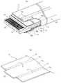
도 5의 (A)는 종래의 시일드 플랫 케이블(1)에 있어서의 단말부(2)를 도시하는 사시도이다. 시일드 플랫 케이블(1)에서는, 복수 개의 평형 도체(3)는 상하로부터 절연 수지 필름(4)[상측 필름(4a), 하측 필름(4b)]으로 개재되어 절연 피복되어 있다. 시일드 플랫 케이블(1)의 단부에서는, 상측 필름(4a)이 제거되어서, 평형 도체(3)의 단자가 되는 부분이 노출되어 케이블 단말부(2)가 형성되어 있다. 또한, 케이블 단말부(2)에서 제거되지 않은 하측 필름(4b)에는 보강 테이프(6)를 부착할 수 있어서 전기 커넥터로의 삽입 접속이 가능한 형태로 되어 있다.FIG. 5A is a perspective view illustrating the
상측 필름(4a)에는, 접지 접속용의 그라운드 테이프(5)가 평형 도체(3)와 전기 단락이 발생하지 않는 위치에 부착되어 있다. 그라운드 테이프(5)는, 접지용으로 된 평형 도체 중 어느 것에 일본 실용 신안 등록 제 3096395 호 공보 또는 일본 특허 공개 제 2005-93178 호 공보에 개시된 방법으로 전기적으로 도통되어 있다(도시 생략). 시일드 플랫 케이블(1)의 외면에는, 예컨대 절연층, 금속층, 도전 접착층의 3층 형상으로 이루어지는 필름인 시일드 필름(7)이 그 일부가 겹치도록 감겨져서, 평형 도체(3)를 외부로부터 시일드하고 있다. 시일드 필름(7)은 그라운드 테이프(5)에 전기적으로 접속하고 있다. 시일드 플랫 케이블(1)의 특성 임피던스는 절연 수지 필름(4)의 비유전율이나 두께 등을 변경함으로써 소정의 값(예컨대, 100Ω 정도)으로 되어 있다.The
시일드 플랫 케이블(1)의 단말부(2)에서는, 전기 커넥터로의 삽입 접속을 위해 평형 도체(3)가 노출되어 있다. 그 때문에, 그라운드 테이프(5)로부터의 끝은 특성 임피던스가 변화한다. 도 5의 (B)는 단말부(2)에 있어서의 특성 임피던스를 설명하는 개념도이다. 케이블 단말부(2)에서 임피던스가 저하한다. 이러한 임피던스의 변화가 신호 전송 경로 중에 존재하면, 전송 신호의 반사가 발생해서 전송 손실이 될 우려가 있다.In the
일본 특허 공개 제 2006-32003 호 공보에는, 플랫 케이블의 특성 임피던스를 소정의 값인 100Ω으로 하는 것이 기재되어 있다. 그러나, 그 단말부의 구성은 명확하게 되어 있지 않아서, 케이블 단말부 근방에서의 임피던스까지의 해명은 이루어질 수 없다. 또한, 전자파 장해(Electro Magnetic Interference ; EMI) 방지 금속 커플링을 부가하는 것이 개시되어 있지만, 시일드층이 없기 때문에, 특성 임피던스와의 관계, 또 EMI를 어떻게 방지하는 것인지는 명확하지 않다.Japanese Laid-Open Patent Publication No. 2006-32003 describes that the characteristic impedance of a flat cable is 100?, Which is a predetermined value. However, the configuration of the terminal portion is not clear, and explanation to the impedance in the vicinity of the cable terminal portion cannot be made. In addition, although it is disclosed to add an electromagnetic interference (EMI) preventive metal coupling, since there is no shield layer, it is not clear how to prevent the relationship with characteristic impedance and EMI.
본 발명의 목적은 케이블 전장에 걸쳐 시일드되며, 또한 케이블 단말부에서의 임피던스의 변화가 적은 시일드 플랫 케이블을 제공하는 것이다.An object of the present invention is to provide a shielded flat cable that is shielded over the entire cable length and has a small change in impedance at the cable end portion.
본 발명의 시일드 플랫 케이블은, 소정의 간격으로 배열된 복수 개의 평형 도체와, 복수 개의 평형 도체를 그 배열면의 상하로부터 사이에 끼워 절연 피복하고 있는 제 1 절연 수지 필름 및 제 2 절연 수지 필름과, 제 1 절연 수지 필름 및 제 2 절연 수지 필름을 덮는 시일드 필름을 포함한다. 또한, 시일드 플랫 케이블은, 적어도 한쪽의 단부에서는 제 1 절연 수지 필름의 선단부가 제거되어서 복수 개의 평형 도체가 제 1 절연 수지 필름 측에서 노출되어 있으며, 제 2 절연 수지 필름의 선단은 복수 개의 평형 도체의 선단과 일치하고 있다. 시일드 플랫 케이블은 단부에 있어서, 제 2 절연 수지 필름의 외면에 부착된 보강 테이프와, 제 1 절연 수지 필름 상에, 일단이 제 1 절연 수지 필름의 단부로부터 소정의 거리를 두고 부착되며 타단이 시일드 필름과 겹쳐 전기적으로 접속되어 있는 제 1 그라운드 테이프와, 보강 테이프 상에 부착되어 그 일부가 시일드 필름과 겹쳐 전기적으로 접속되어 있는 제 2 그라운드 테이프를 포함한다.The shielded flat cable of the present invention includes a plurality of flat conductors arranged at predetermined intervals, and a first insulating resin film and a second insulating resin film which are insulated and covered with a plurality of flat conductors sandwiched from above and below the arrangement surface. And a shield film covering the first insulating resin film and the second insulating resin film. In addition, in the flat shielded cable, the front end of the first insulated resin film is removed at at least one end thereof, so that a plurality of balanced conductors are exposed on the first insulated resin film side, and the ends of the second insulated resin film have a plurality of equilibrium. Coincides with the tip of the conductor. The sealed flat cable has one end attached to the reinforcing tape attached to the outer surface of the second insulating resin film at one end and a first distance from the end of the first insulating resin film and the other end on the first insulating resin film. And a first ground tape overlaid with the shield film and electrically connected thereto, and a second ground tape overlaid on the reinforcement tape and partially connected to the shield film and electrically connected thereto.
본 발명의 하나의 태양에서는, 제 1 그라운드 테이프와 제 2 그라운드 테이프가 일체로 형성되어, 절곡부에서 접혀서 양면에 부착되어 있다. 다른 태양에서는, 시일드 필름은 케이블 길이 방향의 양측 가장자리를 감싸 넣도록 하여 부착되어 있다. 또 다른 태양에서는, 시일드 필름과 절연 수지 필름 사이에 비유전율이 2.2 내지 3.2의 유전체 필름을 배치하여, 임피던스가 소정값으로 조정되어 있다.In one aspect of the present invention, the first ground tape and the second ground tape are integrally formed, and are folded at the bent portion and attached to both surfaces. In another aspect, the shield film is attached by wrapping both edges in the cable longitudinal direction. In still another aspect, a dielectric film having a relative dielectric constant of 2.2 to 3.2 is disposed between the shield film and the insulating resin film, and the impedance is adjusted to a predetermined value.
본 발명에 의하면, 시일드 플랫 케이블의 단말부에서의 특성 임피던스가 변화되는 것을 저감하여, 양호한 신호 전송을 실현할 수 있다.According to the present invention, it is possible to reduce the change in the characteristic impedance at the terminal portion of the shielded flat cable and to realize good signal transmission.
본 발명의 실시형태가 이하에서 도면을 참조하여 설명된다. 도면은 설명을 목적으로 하며, 발명의 범위를 한정하고자 하는 것은 아니다. 도면에 있어서, 설명의 중복을 피하기 위해서 동일한 부호는 동일 부분을 도시한다. 도면 중의 치수의 비율은 반드시 정확하지는 않다.Embodiments of the present invention are described below with reference to the drawings. The drawings are for illustrative purposes and are not intended to limit the scope of the invention. In the drawings, like reference numerals designate like parts in order to avoid duplication of description. The ratio of dimensions in the drawings is not necessarily accurate.
도 1의 (A)는 본 발명의 실시형태에 따른 시일드 플랫 케이블(11)에 있어서의 단말부를 도시하는 사시도이다. 시일드 플랫 케이블(11)에서는, 복수 개의 평형 도체(13)는 상하로부터 절연 수지 필름(14)인 상측 필름(14a)(제 1 절연 수지 필름)과 하측 필름(14b)(제 2 절연 수지 필름)으로 개재되어 절연 피복되어 있다. 그리고, 그 적어도 한쪽의 단부에서, 상측 필름(14a)이 제거되고 평형 도체(13)의 접속 단자가 되는 부분이 노출되어 케이블 단말부(12)가 형성되어 있다. 또한, 케이블 단말부(12)에서, 제거되지 않은 하측 필름(14b)에는 보강 테이프(16)가 부착되어서 강도가 보강되고, 전기 커넥터(도시하지 않음)로의 삽입 접속이 가능한 형상으로 되어 있다. 보강 테이프(16)의 단부는 하측 절연 수지 필름(14b)의 단부와 일치시켜 단부 전체를 보강하는 것이 강도의 면에서 바람직하다.1: (A) is a perspective view which shows the terminal part in the shielded
상측 필름(14a)에는 접지 접속용의 그라운드 테이프(15a)(제 1 그라운드 테이프)가 부착되어 있다. 그라운드 테이프(15a)는 상측 필름(14a)의 선단 근처에서 노출하고 있는 평형 도체(13)와 전기적으로 단락이 발생하지 않는 정도(예컨대, 3㎜∼4㎜) 떨어져 있다. 또한, 후술하는 바와 같이, 그라운드 테이프(15a)는 평형 도체(13)중 어느 것과 전기적으로 도통되어서 접지 접속되어 있다.A
보강 테이프(16)의 하면에도 그라운드 테이프(15a)와 같은 그라운드 테이프(15b)(제 2 그라운드 테이프)가 부착되어 있다. 그라운드 테이프(15a)와 그라운드 테이프(15b)는 평형 도체(13)를 개재해서 서로 마주 보고 있다. 그라운드 테이프(15b)는 그 선단이 그라운드 테이프(15a)의 선단으로부터 거리(T)로 도시하는 바와 같이 단부측에 있으며, 시일드 플랫 케이블(11)이 전기 커넥터에 삽입 접속되었을 때에 커넥터 접촉자 사이와 전기적으로 단락하지 않도록 부착되어 있다. 그라운드 테이프(15b)를 마련함으로써, 커넥터와 그라운드 테이프 사이에서 커패시턴스가 크게 변화되는 것을 회피하고, 특성 임피던스가 크게 변화되는 것을 억제할 수 있다.A
시일드 필름(17a, 17b)은 그라운드 테이프(15a, 15b)의 일부에 겹치도록 하고, 거의 케이블 전장에 걸쳐 케이블을 상하로부터 사이에 끼워 부착되며, 양측 가장자리의 귀부(20)를 서로 접착해서 폐쇄되어 있다. 시일드 필름(17a, 17b)은 그라운드 테이프(15a, 15b)를 거쳐서 접지 접속되어, 케이블에 시일드 기능을 갖게 하고 있다. 또한, 시일드 필름(17a, 17b)은 신호선으로서 동작하는 복수 개의 평형 도체(13)와의 사이에서, 단말 근방을 제외한 케이블 영역에서 균일한 커패시턴스(컨덴서 용량)를 형성하고, 균일한 임피던스를 실현하고 있다.The
특성 임피던스는 신호선이 되는 평형 도체(13)와 시일드 필름(17a, 17b) 사이에 분포되는 컨덴서 용량에 의해 결정된다. 이 컨덴서 용량은 절연 수지 필름(14)의 비유전율이나 필름 두께를 변경함으로써 설정하는 것이 가능하다. 절연 수지 필름(14)만으로는 소정의 특성 임피던스(예컨대, LVDS용의 100Ω)를 얻는 것이 어려울 경우에는, 절연 수지 필름(14)과 시일드 필름(17a, 17b)의 사이에 저유전율의 저유전체 필름(18a, 18b)을 배치함으로써 소정의 특성 임피던스로 한다.The characteristic impedance is determined by the capacitor capacitance distributed between the
도 1의 (B)는 시일드 플랫 케이블(11)의 a-a 단면도이다. 평형 도체(13)는, 예컨대 동박, 주석 도금 연동박 등의 도전성 금속박으로 이루어진다. 평형 도체(13)의 치수와 배치는 신호 전송의 전류값과 케이블의 접동성을 고려하면, 두께 12㎛∼50㎛, 폭 0.2㎜∼0.3㎜ 정도, 0.3㎜∼0.5㎜ 간격이다.1B is a cross-sectional view of the shielded
상측 필름(14a), 하측 필름(14b) 각각은 절연층(28)과 접착제층(22)의 2층으로 이루어진다. 절연층(28)은 유연성이 뛰어난 수지 재료가 사용되며, 예컨대 폴리에스테르 수지, 폴리페닐렌설파이드 수지, 폴리이미드 수지 등의 범용성이 있는 수지 필름으로, 그 두께는 9㎛∼50㎛이다. 폴리에스테르 수지로서는 폴리에틸렌테레프탈레이트 수지, 폴리에틸렌나프탈레이트 수지, 폴리부틸렌나프탈레이트 수지 등의 수지 재료를 들 수 있다. 또한, 이들 수지 필름 중, 전기적 특성, 기계적 특성, 비용 등의 관점으로부터는 폴리에틸렌테레프탈레이트 수지의 사용이 바람직하다. 또한, 폴리이미드나 폴리페닐렌설파이드로 이루어진 수지 필름을 사용함으로써, 미국 보험업자안전시험소(Underwriters Laboratories Inc.)가 발행하는 안전 인증(UL 규격)을 만족시키는 내열성을 갖게 하는 것이 가능해진다.Each of the
접착제층(22)은 수지 재료로 이루어진 것이 사용되며, 예컨대 폴리에스테르계 수지나 폴리올레핀계 수지에 난연제를 첨가한 접착제 등을 들 수 있다. 이 접착제층은 두께 20㎛∼50㎛로 형성되어 있다. 상측 필름(14a)과 하측 필름(14b)은 평형 도체(13)를 개재해서 접착제층(22)을 마주 보게 해서 가열 롤러로 열을 가하면서 접합함으로써, 부착하여 맞춰서 일체화되어 있다.The
제 1 및 제 2 그라운드 테이프(15a, 15b)는 도전층(23)과 접착제층(24)으로 이루어진다. 도전층(23)은 예컨대 두께가 18㎛∼35㎛ 정도의 주석 도금 동박이 사용되며, 굴곡 내성을 고려하여 압연 동박을 사용하는 것이 바람직하다. 접착제층(24)은, 예컨대 아크릴계의 접착층, 수지 기재, 접착층의 순으로 적층되며, 도전층(23)과 합친 전체의 두께는 커넥터의 치수에 맞춰서 85㎛∼125㎛ 정도로 되는 것이 사용된다. 그라운드 테이프(15a, 15b)는 테이프 형상의 것을 소정의 길이로 잘라서 상측 필름, 하측 필름에 부착되어 있다.The first and
시일드 필름(17a, 17b)은, 예컨대 수지층(25)과 시일드층(26)과 도전 접착층(27)의 3층 구조의 것이 사용된다. 수지층(25)은 필름 기재이며, 시일드층(26)의 박리나 부식을 방지하여, 케이블의 신뢰성 유지를 도모하는 것이다. 수지층(25)에는 폴리에틸렌테레프탈레이트의 두께 9㎛ 정도의 수지 필름이 사용된다. 시일드층(26)은, 예컨대 수지층(25)의 수지 필름의 이면에 은 등의 도전성 금속을 증착해서 형성된다.As for the
도전 접착층(27)은 절연 수지 필름(14)으로의 부착 이외에, 그라운드 테이프(15a, 15b)와의 전기적 도통을 얻어서 시일드 기능을 발생시키는 것으로, 예컨대 시일드층(26)의 은 증착면에 은 페이스트(paste)를 도포해서 형성되어 있다. 시일드 필름(17a, 17b)은 전체의 두께가 30㎛ 정도로, 상하로 나누어서 절연 수지 필름(14)의 외주에 직접 또는 저유전체 필름(18a, 18b)을 거쳐서 부착되어 있다.In addition to adhesion to the insulating
그라운드 테이프(15a, 15b)의 도전층(23)은 그 일부가 시일드 필름(17)의 도전 접착층(27)과 전기적으로 접촉하고 있다. 또한, 절연 수지 필름(14a, 14b) 중 평형 도체(13)의 어느 것이 그라운드 선이 되지만 상부 또는 하부의 부분이 길이 방향으로 적어도 일부 제거되어서, 그라운드 선과 시일드 필름(17)의 도전 접착층(27)이 전기적으로 접촉되어 있다. 저유전체 필름(18a, 18b)이 있을 경우에는, 저유전체 필름(18a, 18b)의 일부도 제거되어서, 그라운드 선과 도전 접착층(27)이 전기적으로 접촉되어 있다. 이렇게 해서, 그라운드 테이프(15a, 15b), 시일드 필름(17) 및 그라운드 선은 전기적으로 도통되어 있다. 그라운드 선을 접지함으로써, 그라운드 테이프 및 시일드 필름도 접지된다.A part of the
저유전체 필름(18a, 18b)은 절연 수지 필름(14)만으로는 소정의 특성 임피던스를 얻을 수 없는 경우에 사용된다. 저유전체 필름(18a, 18b)으로서는, 저유전성을 갖는 동시에, 유연성, 가공성이 뛰어난 수지 재료를 주성분으로 하는 것을 사용할 수 있다. 예를 들면, 저유전성과 유연성을 갖는 것으로서는, 폴리올레핀계의 수지로, 폴리프로필렌(PP), 폴리에틸렌 수지(PE), 산변성 폴리에틸렌 수지, 에틸렌초산비닐 공중합체(EVA), 에틸렌에틸아크릴레이트 등을 들 수 있다. 또한, 저유전성과 가공성이 뛰어난 것으로서는, 저밀도 폴리에틸렌 수지(LDPE), 직쇄형 저밀도 폴리에틸렌 수지(LLDPE)를 들 수 있다.The low
저유전체 필름(18a, 18b)은, 예컨대 비유전율이 2.2∼3.2, 두께 100㎛∼350㎛ 정도의 것을 절연 수지 필름(14)에 겹쳐서 사용한다. 이로써, 시일드 플랫 케이블의 특성 임피던스를 50Ω∼110Ω의 범위에서 임의의 값으로 설정하는 것이 가능해진다.The low
도 2의 (A)는 본 발명의 다른 실시형태에 따른 시일드 플랫 케이블(21)에 있어서의 단말부를 도시하는 사시도이다. 시일드 플랫 케이블(21)은 시일드 플랫 케이블(11)에 있어서의 제 1 그라운드 테이프(15a)와 제 2 그라운드 테이프(15b)를 1매의 그라운드 테이프(15)[도 2의 (B)]로 형성하고 있다. 그라운드 테이프(15)는 제 1 그라운드 테이프부(15d)와 제 2 그라운드 테이프부(15e)를 절곡부(15c)를 거쳐서 일체로 형성한 것이다. 또한, 그라운드 테이프(15)에 있어서, 제 2 그라운드 테이프부(15e)측은 제 1 그라운드 테이프부(15d)보다 폭을 도 1의 거리(T)에 상당하는 만큼 크게 하고 있다.2: (A) is a perspective view which shows the terminal part in the shielded
그라운드 테이프(15)는 제 1 그라운드 테이프부(15d)로 평형 도체(13)의 노출된 측의 상측 필름(14a)에 부착되고, 다음에 절곡부(15c)에서 접혀서, 제 2 그라운드 테이프부(15e)로 하측의 보강 테이프(16)의 외면에 부착되어 있다. 그라운드 테이프(15)에서는, 제 1 그라운드 테이프부(15d)와 제 2 그라운드 테이프부(15e)를 각각 개별적으로 접지 접속용으로 설정된 평형 도체와 도통을 취할 필요가 없다. 또한, 제 1 그라운드 테이프부(15d)와 제 2 그라운드 테이프부(15e)는 1매의 그라운드 테이프(15)로서 관리할 수 있으므로, 부품수가 적어 관리하기 쉬워진다.The
도 3의 (A)는 본 발명의 다른 실시형태에 따른 시일드 플랫 케이블(31)에 있어서의 단말부를 도시하는 사시도이다. 시일드 플랫 케이블(31)은 시일드 플랫 케이블(11)에 있어서의 상측의 시일드 필름(17a)과 하측의 시일드 필름(17b)을 한 장의 시일드 필름(17)으로 일체로 형성한 예이다[도 3의 (B)]. 시일드 필름(17)은 중앙부에 하측(보강 테이프측)에 부착되는 시일드 필름(17e)을 가지며, 그 양측부에 절곡부(17c)를 거쳐서 상측에 부착되는 시일드 필름(17d)을 갖는다.3: (A) is a perspective view which shows the terminal part in the shielded
시일드 필름(17e)은 보강 테이프측에 부착되어 있는 제 2 그라운드 테이프(15b)에 부분적으로 겹침을 가지도록 해서 저유전체 필름에 부착되어 있다. 양측의 시일드 필름(17d)의 부분은 절곡부(17c)에서 케이블측 가장자리를 감싸 넣도록 굽혀져서 저유전체 필름에 부착되어 있다. 그리고, 양측의 시일드 필름(17d)은 케이블 상면의 중간측 부분에서 길이 방향을 따라, 겹침을 갖도록 서로 부착되어 폐쇄된다.The
시일드 필름(17)은 상하 2매의 시일드 필름(17a, 17b)을 채용할 경우에 발생하는 귀부(20)가 발생하지 않는다. 이 결과, 귀부(20)에 노출하는 시일드층의 도전체에서, 배선 기기 내에 전기적 단락을 일으킨다고 하는 문제를 회피할 수 있다. 또한, 시일드 필름(17)의 선단(17f)을 그라운드 테이프의 형상에 맞춰서 가공하는 이외에, 테이프 형상의 필름에 각별한 가공을 실시하는 일 없이 그대로 사용할 수 있으며, 1매의 시일드 필름으로 관리할 수 있으므로, 부품수가 적어 관리하기 쉬워진다.As for the sealed
도 4의 (A) 및 (B)는 본 발명의 다른 실시형태에 따른 시일드 플랫 케이블(41A, 41B)에 있어서의 단말부를 도시하는 사시도이다. 케이블(41A)은 시일드 플랫 케이블(11)에 있어서 저유전체 필름을 케이블 단말부의 가장자리까지 마련한 예이며, 케이블(41B)은 시일드 플랫 케이블(31)에 있어서 저유전체 필름을 케이블 단말부의 가장자리까지 마련한 예이다. 시일드 플랫 케이블(41A)에서는, 상측의 그라운드 테이프(15a)는 저유전체 필름(18a)의 상면에 부착되어 있다. 하측에서는 보강 테이프(16)가 절연체로서 기능한다. 이 때문에, 저유전체 필름(18b)을 보강 테이프(16)의 외면에 적층시키지 않아도 좋다. 시일드 플랫 케이블(41B)에서도 시일드 필름(17)의 형상이 다른 것 이외에는 케이블(41A)과 같다.4: (A) and (B) are perspective views which show the terminal part in the shielded
어느 쪽의 예라도, 절연 수지 필름(14)과 적층되어 있는 저유전체 필름(18a, 18b)은 신호선의 평형 도체(13)와 접지되는 시일드 필름(17a, 17b) 사이에 형성되는 컨덴서 용량(커패시턴스)을 변경하여, 소정의 특성 임피던스를 실현하고 있다. 저유전체 필름(18a, 18b)은 그 유전율을 작게 함으로써 특성 임피던스를 크게 하고, 또한 그 두께를 증가하는 것으로, 특성 임피던스를 크게 할 수 있다. 따라서, 시일드 플랫 케이블로 케이블 단말부(12)에서의 특성 임피던스의 변화를 경감하려면, 케이블 단말부의 가장자리까지 될 수 있는 한 균일한 절연체(유전체)가 존재하고 있는 것이 바람직하다.In either case, the low
상술한 바와 같이, 저유전체 필름(18a, 18b)을 지장이 없는 범위에서 케이블 단말부(12)의 가장자리까지 마련함으로써, 케이블 전장에 걸쳐 균일하게 분포하는 컨덴서 용량으로 할 수 있다. 그리고, 상술한 바와 같이, 케이블 단말부에서의 그라운드 테이프를 보강 테이프측에도 마련함으로써, 안정한 소정의 특성 임피던스를 갖는 시일드 플랫 케이블로 할 수 있다.As described above, by providing the low
도 1의 (A)는 본 발명의 실시형태에 따른 시일드 플랫 케이블에 있어서의 단말부를 도시하는 사시도이며, 도 1의 (B)는 도 1의 (A)에 있어서의 a-a 단면을 도시한 도면,1: (A) is a perspective view which shows the terminal part in the shielded flat cable which concerns on embodiment of this invention, FIG. 1 (B) is a figure which shows the aa cross section in FIG. ,
도 2의 (A)는 본 발명의 다른 실시형태에 따른 시일드 플랫 케이블에 있어서의 단말부를 도시하는 사시도이며, 도 2의 (B)는 이 실시형태에 있어서의 그라운드 테이프를 도시하는 사시도,FIG. 2A is a perspective view showing a terminal portion in a shielded flat cable according to another embodiment of the present invention, and FIG. 2B is a perspective view showing a ground tape in this embodiment;
도 3의 (A)는 본 발명의 또 다른 실시형태에 따른 시일드 플랫 케이블에 있어서의 단말부를 도시하는 사시도이며, 도 3의 (B)는 이 실시형태에 있어서의 시일드 필름을 도시하는 사시도,3: (A) is a perspective view which shows the terminal part in the shielded flat cable which concerns on another embodiment of this invention, and FIG. 3 (B) is a perspective view which shows the shield film in this embodiment. ,
도 4의 (A) 및 (B)는 본 발명의 또 다른 실시형태에 따른 시일드 플랫 케이블에 있어서의 단말부를 도시하는 사시도,4 (A) and (B) are perspective views showing a terminal portion in a shielded flat cable according to still another embodiment of the present invention;
도 5의 (A)는 종래의 시일드 플랫 케이블에 있어서의 단말부를 도시하는 사시도이며, 도 5의 (B)는 단말부에 있어서의 특성 임피던스를 설명하는 개념도.Fig. 5A is a perspective view showing a terminal portion in a conventional shielded flat cable, and Fig. 5B is a conceptual diagram illustrating characteristic impedance in the terminal portion.
도면의 주요 부분에 대한 부호의 설명Explanation of symbols for the main parts of the drawings
11, 21, 31, 41A, 41B : 시일드 플랫 케이블11, 21, 31, 41A, 41B: Sealed Flat Cable
12 : 케이블 단말부13 : 평형 도체12
14 : 절연 수지 필름14a : 제 1 절연 수지 필름14: insulating
14b : 제 2 절연 수지 필름15a : 제 1 그라운드 테이프14b: 2nd insulating
15b : 제 2 그라운드 테이프15c : 절곡부15b:
16 : 보강 테이프17a, 17b : 시일드 필름16:
18a, 18b : 저유전체 필름20 : 귀부18a, 18b: low dielectric film 20: ear
23 : 도전층24 : 접착제층23: conductive layer 24: adhesive layer
25 : 수지층26 : 시일드층25: resin layer 26: shield layer
27 : 도전 접착층27: conductive adhesive layer
Claims (4)
Translated fromKoreanPriority Applications (1)
| Application Number | Priority Date | Filing Date | Title |
|---|---|---|---|
| KR1020090019908AKR101056324B1 (en) | 2009-03-09 | 2009-03-09 | Shielded flat cable |
Applications Claiming Priority (1)
| Application Number | Priority Date | Filing Date | Title |
|---|---|---|---|
| KR1020090019908AKR101056324B1 (en) | 2009-03-09 | 2009-03-09 | Shielded flat cable |
Publications (2)
| Publication Number | Publication Date |
|---|---|
| KR20100101422A KR20100101422A (en) | 2010-09-17 |
| KR101056324B1true KR101056324B1 (en) | 2011-08-11 |
Family
ID=43006950
Family Applications (1)
| Application Number | Title | Priority Date | Filing Date |
|---|---|---|---|
| KR1020090019908AActiveKR101056324B1 (en) | 2009-03-09 | 2009-03-09 | Shielded flat cable |
Country Status (1)
| Country | Link |
|---|---|
| KR (1) | KR101056324B1 (en) |
Families Citing this family (4)
| Publication number | Priority date | Publication date | Assignee | Title |
|---|---|---|---|---|
| KR101219357B1 (en)* | 2011-09-28 | 2013-01-09 | 주식회사 영 신 | Flexible flat cable of electromagnetic waves screening style |
| JP6801306B2 (en)* | 2016-08-31 | 2020-12-16 | 住友電気工業株式会社 | Shielded flat cable |
| CN110322990B (en)* | 2018-03-28 | 2021-07-16 | 贝尔威勒电子(昆山)有限公司 | Flexible flat cable for high-frequency signal transmission |
| JP7294329B2 (en)* | 2018-04-27 | 2023-06-20 | 住友電気工業株式会社 | connector and board |
Citations (1)
| Publication number | Priority date | Publication date | Assignee | Title |
|---|---|---|---|---|
| KR20080014820A (en)* | 2005-05-23 | 2008-02-14 | 쓰리엠 이노베이티브 프로퍼티즈 컴파니 | Flat cable shield ground connection |
- 2009
- 2009-03-09KRKR1020090019908Apatent/KR101056324B1/enactiveActive
Patent Citations (1)
| Publication number | Priority date | Publication date | Assignee | Title |
|---|---|---|---|---|
| KR20080014820A (en)* | 2005-05-23 | 2008-02-14 | 쓰리엠 이노베이티브 프로퍼티즈 컴파니 | Flat cable shield ground connection |
Also Published As
| Publication number | Publication date |
|---|---|
| KR20100101422A (en) | 2010-09-17 |
Similar Documents
| Publication | Publication Date | Title |
|---|---|---|
| JP5119898B2 (en) | Shielded flat cable | |
| US11289241B2 (en) | Shielded flat cable | |
| JP7196909B2 (en) | shielded flat cable | |
| JP2594734Y2 (en) | Flat cable with shield | |
| TWI453768B (en) | Composite flexible circuit cable | |
| JP6721104B2 (en) | Shielded flat cable | |
| TWI409985B (en) | Flat cable | |
| JP5309766B2 (en) | Shielded flat cable | |
| JP6801306B2 (en) | Shielded flat cable | |
| CN101819830B (en) | Shielded flat cable | |
| JP7067275B2 (en) | Shielded flat cable | |
| JP5499722B2 (en) | Shielded flat cable | |
| KR101056324B1 (en) | Shielded flat cable | |
| JP2018181565A (en) | Flat cable with shield layer | |
| CN101840749B (en) | Shielded flat cable | |
| CN202076032U (en) | Shielding flat electric cable | |
| TWI397085B (en) | Shield flat cable | |
| JP2008300343A (en) | Signal transmission cable | |
| CN212303122U (en) | A stable FFC | |
| JP7298612B2 (en) | FLAT CABLE AND FLAT CABLE MANUFACTURING METHOD | |
| JP5593734B2 (en) | Shielded flat cable, shielded flat cable with connector, and manufacturing method thereof | |
| JP2010102975A (en) | Shielded flat cable | |
| JP2011146270A (en) | Flat cable | |
| JP2979883B2 (en) | Flat cable with shield | |
| CN120414185A (en) | Transmission line structure and data transmission module |
Legal Events
| Date | Code | Title | Description |
|---|---|---|---|
| PA0109 | Patent application | St.27 status event code:A-0-1-A10-A12-nap-PA0109 | |
| A201 | Request for examination | ||
| P11-X000 | Amendment of application requested | St.27 status event code:A-2-2-P10-P11-nap-X000 | |
| P13-X000 | Application amended | St.27 status event code:A-2-2-P10-P13-nap-X000 | |
| PA0201 | Request for examination | St.27 status event code:A-1-2-D10-D11-exm-PA0201 | |
| PG1501 | Laying open of application | St.27 status event code:A-1-1-Q10-Q12-nap-PG1501 | |
| E902 | Notification of reason for refusal | ||
| PE0902 | Notice of grounds for rejection | St.27 status event code:A-1-2-D10-D21-exm-PE0902 | |
| R17-X000 | Change to representative recorded | St.27 status event code:A-3-3-R10-R17-oth-X000 | |
| E13-X000 | Pre-grant limitation requested | St.27 status event code:A-2-3-E10-E13-lim-X000 | |
| P11-X000 | Amendment of application requested | St.27 status event code:A-2-2-P10-P11-nap-X000 | |
| P13-X000 | Application amended | St.27 status event code:A-2-2-P10-P13-nap-X000 | |
| E701 | Decision to grant or registration of patent right | ||
| PE0701 | Decision of registration | St.27 status event code:A-1-2-D10-D22-exm-PE0701 | |
| GRNT | Written decision to grant | ||
| PR0701 | Registration of establishment | St.27 status event code:A-2-4-F10-F11-exm-PR0701 | |
| PR1002 | Payment of registration fee | St.27 status event code:A-2-2-U10-U11-oth-PR1002 Fee payment year number:1 | |
| PG1601 | Publication of registration | St.27 status event code:A-4-4-Q10-Q13-nap-PG1601 | |
| FPAY | Annual fee payment | Payment date:20140721 Year of fee payment:4 | |
| PR1001 | Payment of annual fee | St.27 status event code:A-4-4-U10-U11-oth-PR1001 Fee payment year number:4 | |
| FPAY | Annual fee payment | Payment date:20150716 Year of fee payment:5 | |
| PR1001 | Payment of annual fee | St.27 status event code:A-4-4-U10-U11-oth-PR1001 Fee payment year number:5 | |
| FPAY | Annual fee payment | Payment date:20160630 Year of fee payment:6 | |
| PR1001 | Payment of annual fee | St.27 status event code:A-4-4-U10-U11-oth-PR1001 Fee payment year number:6 | |
| P22-X000 | Classification modified | St.27 status event code:A-4-4-P10-P22-nap-X000 | |
| FPAY | Annual fee payment | Payment date:20170720 Year of fee payment:7 | |
| PR1001 | Payment of annual fee | St.27 status event code:A-4-4-U10-U11-oth-PR1001 Fee payment year number:7 | |
| FPAY | Annual fee payment | Payment date:20180717 Year of fee payment:8 | |
| PR1001 | Payment of annual fee | St.27 status event code:A-4-4-U10-U11-oth-PR1001 Fee payment year number:8 | |
| PR1001 | Payment of annual fee | St.27 status event code:A-4-4-U10-U11-oth-PR1001 Fee payment year number:9 | |
| PR1001 | Payment of annual fee | St.27 status event code:A-4-4-U10-U11-oth-PR1001 Fee payment year number:10 | |
| PR1001 | Payment of annual fee | St.27 status event code:A-4-4-U10-U11-oth-PR1001 Fee payment year number:11 | |
| PR1001 | Payment of annual fee | St.27 status event code:A-4-4-U10-U11-oth-PR1001 Fee payment year number:12 | |
| PR1001 | Payment of annual fee | St.27 status event code:A-4-4-U10-U11-oth-PR1001 Fee payment year number:13 | |
| PR1001 | Payment of annual fee | St.27 status event code:A-4-4-U10-U11-oth-PR1001 Fee payment year number:14 | |
| PR1001 | Payment of annual fee | St.27 status event code:A-4-4-U10-U11-oth-PR1001 Fee payment year number:15 |