KR101055573B1 - Precoding Device in Multi-User, Multi-antenna Radio Transmission System - Google Patents
Precoding Device in Multi-User, Multi-antenna Radio Transmission SystemDownload PDFInfo
- Publication number
- KR101055573B1 KR101055573B1KR1020090022358AKR20090022358AKR101055573B1KR 101055573 B1KR101055573 B1KR 101055573B1KR 1020090022358 AKR1020090022358 AKR 1020090022358AKR 20090022358 AKR20090022358 AKR 20090022358AKR 101055573 B1KR101055573 B1KR 101055573B1
- Authority
- KR
- South Korea
- Prior art keywords
- coefficient
- signal
- transmission
- antenna
- precoding
- Prior art date
- Legal status (The legal status is an assumption and is not a legal conclusion. Google has not performed a legal analysis and makes no representation as to the accuracy of the status listed.)
- Active
Links
- 230000005540biological transmissionEffects0.000titleclaimsabstractdescription56
- 239000011159matrix materialSubstances0.000claimsabstractdescription18
- 238000000034methodMethods0.000claimsabstractdescription17
- 230000008054signal transmissionEffects0.000claimsdescription8
- 238000013461designMethods0.000description5
- 238000010586diagramMethods0.000description2
- 238000005562fadingMethods0.000description2
- 238000006243chemical reactionMethods0.000description1
- 238000004891communicationMethods0.000description1
- 238000012986modificationMethods0.000description1
- 230000004048modificationEffects0.000description1
- 238000005457optimizationMethods0.000description1
- 238000012545processingMethods0.000description1
- 238000011084recoveryMethods0.000description1
- 238000012546transferMethods0.000description1
Images


Classifications
- H—ELECTRICITY
- H04—ELECTRIC COMMUNICATION TECHNIQUE
- H04B—TRANSMISSION
- H04B7/00—Radio transmission systems, i.e. using radiation field
- H04B7/02—Diversity systems; Multi-antenna system, i.e. transmission or reception using multiple antennas
- H04B7/04—Diversity systems; Multi-antenna system, i.e. transmission or reception using multiple antennas using two or more spaced independent antennas
- H04B7/0413—MIMO systems
- H04B7/0426—Power distribution
- H04B7/0434—Power distribution using multiple eigenmodes
- H—ELECTRICITY
- H04—ELECTRIC COMMUNICATION TECHNIQUE
- H04B—TRANSMISSION
- H04B7/00—Radio transmission systems, i.e. using radiation field
- H04B7/02—Diversity systems; Multi-antenna system, i.e. transmission or reception using multiple antennas
- H04B7/04—Diversity systems; Multi-antenna system, i.e. transmission or reception using multiple antennas using two or more spaced independent antennas
- H04B7/0413—MIMO systems
- H04B7/0452—Multi-user MIMO systems
- H—ELECTRICITY
- H04—ELECTRIC COMMUNICATION TECHNIQUE
- H04B—TRANSMISSION
- H04B7/00—Radio transmission systems, i.e. using radiation field
- H04B7/02—Diversity systems; Multi-antenna system, i.e. transmission or reception using multiple antennas
- H04B7/04—Diversity systems; Multi-antenna system, i.e. transmission or reception using multiple antennas using two or more spaced independent antennas
- H04B7/0413—MIMO systems
- H04B7/0456—Selection of precoding matrices or codebooks, e.g. using matrices antenna weighting
- H—ELECTRICITY
- H04—ELECTRIC COMMUNICATION TECHNIQUE
- H04B—TRANSMISSION
- H04B7/00—Radio transmission systems, i.e. using radiation field
- H04B7/02—Diversity systems; Multi-antenna system, i.e. transmission or reception using multiple antennas
- H04B7/04—Diversity systems; Multi-antenna system, i.e. transmission or reception using multiple antennas using two or more spaced independent antennas
- H04B7/06—Diversity systems; Multi-antenna system, i.e. transmission or reception using multiple antennas using two or more spaced independent antennas at the transmitting station
- H04B7/0613—Diversity systems; Multi-antenna system, i.e. transmission or reception using multiple antennas using two or more spaced independent antennas at the transmitting station using simultaneous transmission
- H04B7/0615—Diversity systems; Multi-antenna system, i.e. transmission or reception using multiple antennas using two or more spaced independent antennas at the transmitting station using simultaneous transmission of weighted versions of same signal
- H04B7/0617—Diversity systems; Multi-antenna system, i.e. transmission or reception using multiple antennas using two or more spaced independent antennas at the transmitting station using simultaneous transmission of weighted versions of same signal for beam forming
- H—ELECTRICITY
- H04—ELECTRIC COMMUNICATION TECHNIQUE
- H04B—TRANSMISSION
- H04B7/00—Radio transmission systems, i.e. using radiation field
- H04B7/02—Diversity systems; Multi-antenna system, i.e. transmission or reception using multiple antennas
- H04B7/04—Diversity systems; Multi-antenna system, i.e. transmission or reception using multiple antennas using two or more spaced independent antennas
- H04B7/06—Diversity systems; Multi-antenna system, i.e. transmission or reception using multiple antennas using two or more spaced independent antennas at the transmitting station
- H04B7/0613—Diversity systems; Multi-antenna system, i.e. transmission or reception using multiple antennas using two or more spaced independent antennas at the transmitting station using simultaneous transmission
- H04B7/0615—Diversity systems; Multi-antenna system, i.e. transmission or reception using multiple antennas using two or more spaced independent antennas at the transmitting station using simultaneous transmission of weighted versions of same signal
- H04B7/0619—Diversity systems; Multi-antenna system, i.e. transmission or reception using multiple antennas using two or more spaced independent antennas at the transmitting station using simultaneous transmission of weighted versions of same signal using feedback from receiving side
- H04B7/0621—Feedback content
- H04B7/0626—Channel coefficients, e.g. channel state information [CSI]
Landscapes
- Engineering & Computer Science (AREA)
- Computer Networks & Wireless Communication (AREA)
- Signal Processing (AREA)
- Power Engineering (AREA)
- Radio Transmission System (AREA)
- Transmitters (AREA)
- Mobile Radio Communication Systems (AREA)
Abstract
Translated fromKoreanDescription
Translated fromKorean본 발명은 다중 안테나를 통한 무선 전송 기술에 관련되며, 특히 다중 사용자, 다중 안테나 무선 송출 시스템에서 모든 사용자에게 균일한 수신 특성을 보장할 수 있는 프리코딩 기술에 관련된다.TECHNICAL FIELD The present invention relates to a radio transmission technique through a multi-antenna, and more particularly to a precoding technique capable of ensuring uniform reception characteristics to all users in a multi-user, multi-antenna radio transmission system.
한정된 주파수 대역을 효율적으로 사용하기 위한 방안으로 다중 안테나를 사용하는 MIMO(multiple-input and multiple-output) 기술이 알려져 있다. MIMO 에서는 전송의 신뢰성을 높이기 위해 공간-시간 코딩(space-time coding) 기법을 사용한다. 이는 입력 신호를 복수의 안테나를 통해 시간, 공간적으로 중복하여 전송하거나 시간, 공간적으로 분할 전송하기 위한 사전 신호처리이다.In order to efficiently use a limited frequency band, a multiple-input and multiple-output (MIMO) technique using multiple antennas is known. MIMO uses space-time coding to improve the reliability of transmission. This is a preliminary signal processing for transmitting an input signal through a plurality of antennas in time and space and overlapping or splitting time and space.
MIMO에서는 복수의 안테나를 통해 정보를 중복 전송함으로써 전송의 신뢰도를 높이는 공간 다이버시티(spatial diversity) 기법과, 복수의 안테나를 통해 정보를 분할해 전송함으로써 채널을 실질적으로 확장하는 공간 다중화(spatial multiplexing) 기법이 알려져 있다.MIMO uses spatial diversity to improve transmission reliability by redundantly transmitting information through multiple antennas, and spatial multiplexing to substantially expand a channel by dividing and transmitting information through multiple antennas. Techniques are known.
본 발명은 전송단에서 다중 안테나를 통해 다수의 사용자에게 동시에 정보를 전달하고 각 사용자는 하나의 안테나를 사용하여 신호를 수신하는 MU-MIMO(multi-user multiple-input and multiple-output) 다중 사용자 전송을 지원하기 위한 프리코딩(precoding) 기술에 관한 것이다.The present invention transmits information to multiple users at the same time through multiple antennas at a transmitting end, and each user uses a single antenna to receive a signal using a multi-user multiple-input and multiple-output (MU-MIMO) multi-user transmission. It relates to a precoding technique for supporting the.
고속 정보 전송을 지원하기 위해 MIMO를 사용한 공간 다중화(spatial multiplexing) 기법에 대한 다양한 기술들과 사용방법들이 연구되었다. MIMO을 사용한 다중 사용자 전송은 동시에 여러 사용자에게 정보 전송이 가능하여 시스템의 전송 용량을 증가시키고 보다 효과적인 대역 할당을 가능하게 한다. 그러나 수신단에 다중 안테나가 사용되지 않을 경우 신호 간 간섭에 의해 신호의 수신 및 복호 성능이 크게 저하된다는 단점이 있다.In order to support high-speed information transmission, various techniques and methods of spatial multiplexing using MIMO have been studied. Multi-user transmission using MIMO enables simultaneous transmission of information to multiple users, increasing the transmission capacity of the system and enabling more efficient band allocation. However, when multiple antennas are not used at the receiving end, signal reception and decoding performance is greatly deteriorated by interference between signals.
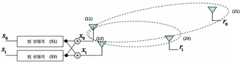
도 1은 두 개의 전송 안테나를 사용하여 동시에 두 사용자에게 정보를 전달하는 MIMO 시스템의 일 예를 개략적으로 도시한다. S0, S1 은 각각 두 개의 안테나를 통해 전송되는 신호를, hn은 각 채널의 페이딩(fading) 특성값, 그리고 rn은 각 사용자의 수신 신호를 나타낸다. 그림에서 안테나들을 상호 연결한 실선은 정보가 의도된 사용자에게 전달되는 경로를, 점선은 다른 사용자의 신호가 간섭으로 수신되는 경로를 표현한다.1 schematically illustrates an example of a MIMO system using two transmit antennas to simultaneously transmit information to two users. S0 and S1 each represent a signal transmitted through two antennas, hn represents a fading characteristic value of each channel, and rn represents a received signal of each user. In the figure, the solid line interconnecting the antennas represents the path through which information is delivered to the intended user, and the dotted line represents the path through which another user's signal is received due to interference.
도 1에 도시된 시스템의 경우, 각 사용자는 다른 사용자의 신호를 동시에 수신하게 된다. 이때 다른 사용자의 신호가 비교적 큰 값으로 수신되는 경우 정보를 복원할 수 없다. 이를 수식으로 표현하면,In the system shown in FIG. 1, each user simultaneously receives signals from other users. In this case, when a signal of another user is received with a relatively large value, the information cannot be restored. If you express it as a formula,

로 된다..
위 수식에서 h0 와 h3 가 각각 h2 또는 h1 보다 월등히 큰 경우 정보 전송이 효과적으로 수행되나 그렇지 않은 경우 사용자는 간섭에 의한 복원 성능 저하를 겪게 된다.In the above formula, when h0 and h3 are significantly larger than h2 or h1 , respectively, information transmission is effectively performed, but otherwise, the user suffers from restoration performance due to interference.
도 2는 빔 성형(beam forming)을 통해 두 사용자에게 동시에 정보를 전달하는 일 예를 도시한다. 도면에서 점선은 성형된 빔의 성상도를 나타낸다. 이 예의 경우, 신호 전송의 방향성을 이용하여 사용자들을 구분한다. 사용자들이 전송단에서 각기 다른 방향에 존재 할 경우 효과적인 정보 전송이 가능하나 도 2에 도시된 예와 같이 사용자가 기지국에서 보았을 때 동일하거나 매우 근접한 방향에 위치한 경우 도시된 바로부터 확인 할 수 있듯이 사용자들의 신호간 간섭이 발생하며 이로 인해 수신된 신호의 복원 가능성을 크게 저하시킨다.2 illustrates an example of simultaneously transmitting information to two users through beam forming. Dotted lines in the figures represent constellations of the shaped beams. In this example, the users are distinguished using the directionality of the signal transmission. If the users are in different directions in the transmitting end, effective information transmission is possible, but as shown in the example shown in FIG. 2, when the users are located in the same or very close direction when viewed from the base station, as shown in FIG. Inter-signal interference occurs, which greatly reduces the likelihood of recovery of the received signal.
본 발명은 다중 안테나를 통해 다수의 사용자에게 신호를 전송할 때 각 사용자들이 평균적으로 최적의 수신을 할 수 있도록 하는 프리코더를 제공하는 것을 목적으로 한다.It is an object of the present invention to provide a precoder that enables each user to achieve optimal reception on average when transmitting signals to multiple users through multiple antennas.
나아가 본 발명은 이 같은 프리코더의 계산을 간단하게 하는 것을 목적으로 한다.Furthermore, an object of the present invention is to simplify the calculation of such a precoder.
나아가 본 발명은 빠르게 변하는 채널 상황에 적합한 프리코드 장치를 제공한다.Furthermore, the present invention provides a precode device suitable for a rapidly changing channel situation.
상기 목적을 달성하기 위한 MU-MIMO(multi-user multiple-input and multiple-output) 방식의 무선 송출단을 위한 본 발명에 따른 프리코딩(precoding) 장치는 신호 전송 측에서 전송 신호에 의한 간섭 및 잡음의 강도에 대한 전송 신호의 수신단 수신 전력의 비율을 최대화하는 계수 값을 가진다.A precoding apparatus according to the present invention for a wireless transmitter of a multi-user multiple-input and multiple-output (MU-MIMO) scheme for achieving the above object is interference and noise caused by a transmission signal at a signal transmission side. It has a coefficient value that maximizes the ratio of the receiving power of the receiving end of the transmission signal to the strength of.
각 수신 단말기 입장에서 신호대간섭비를 최대로 하는 프리코딩 행렬은 계수값이 채널 특성 계수에 대해 미분이 불가능한 형태로 주어져 연산이 대단히 복잡하다. 본 발명은 발상의 전환을 통해 신호 전송 측에서 전송신호의 수신 전력이 그 전송신호에 의한 간섭 및 잡음의 강도에 비해 최대화되도록 프리코딩 행렬을 산출하며, 이는 확정형 해답(closed form solution)을 제시하여 빠르게 변하는 채널 상황에서도 신속한 계산으로 대응이 가능하다.The operation of the precoding matrix that maximizes the signal-to-interference ratio for each receiver terminal is very complicated because the coefficients are given in such a way that they cannot be differentiated with respect to the channel characteristic coefficients. The present invention calculates a precoding matrix such that the reception power of a transmission signal at the signal transmission side is maximized in comparison with the strength of interference and noise caused by the transmission signal through the conversion of the idea, which presents a closed form solution. Therefore, it is possible to respond with quick calculation even in a rapidly changing channel situation.
또한 본 발명에 따른 다중 수신 단말기를 위한 다중 안테나 무선 송출 장치는 송신측 안테나와 수신측 안테나 간의 무선 전송 채널의 특성 값을 획득하는 채널특성획득부와, 신호 전송 측에서 전송 신호에 의한 간섭 및 잡음의 강도에 대한 전송 신호의 수신단 수신 전력의 비율을 최대화하는 계수 값들을 상기 전송 채널 특성 계수의 함수로 구하는 계수산출부와, 상기 계수 산출부에서 구해진 행렬로 입력 신호를 곱해서 출력하는 프리코딩부를 포함한다.In addition, the multi-antenna wireless transmitting apparatus for a multi-receiving terminal according to the present invention is a channel characteristic acquisition unit for obtaining a characteristic value of the radio transmission channel between the transmitting antenna and the receiving antenna, the interference and noise caused by the transmission signal at the signal transmission side A coefficient calculating unit for obtaining coefficient values for maximizing a ratio of reception power of a receiving end of a transmission signal to a strength of a signal as a function of the transmission channel characteristic coefficients, and a precoding unit for multiplying and outputting an input signal with a matrix obtained from the coefficient calculating unit do.
본 발명은 적절한 프리코드 설계를 통해 각 사용자의 평균 수신 성능을 개선시키며 이를 통해 시스템의 전반적 성능을 향상시킨다. 또한 본 발명은 확정형으로 주어지는 프리코드 설계를 통해 낮은 하드웨어 복잡도(hardware complexity)로 프리코드 구현이 가능하도록 한다.The present invention improves the average reception performance of each user through proper precode design, thereby improving the overall performance of the system. In addition, the present invention enables precode implementation with low hardware complexity through a precode design given in a deterministic form.
나아가 본 발명은 빠르게 변하는 채널 상황에서도 고속으로 채널에 적응적으로 프리코딩을 수행하므로, 항상 수신 단말기 입장에서 최적의 수신 성능을 유지할 수 있는 장점이 있다.Furthermore, since the present invention adaptively performs precoding to a channel at high speed even in a rapidly changing channel situation, there is an advantage of always maintaining optimal reception performance from a receiver terminal point of view.
전술한, 그리고 추가적인 본 발명의 양상들은 후술하는 실시예들을 통해 더욱 명확해질 것이다. 이하에서는 이 같은 본 발명의 양상들을 첨부된 도면을 참조하여 기술되는 바람직한 실시예들을 통해 당업자가 이해하고 재현할 수 있도록 설명하기로 한다.The foregoing and further aspects of the present invention will become more apparent through the following embodiments. DETAILED DESCRIPTION Hereinafter, exemplary embodiments of the present invention will be described to be understood and reproduced by those skilled in the art through preferred embodiments described with reference to the accompanying drawings.
본 발명은 사용자들이 동일한 수신 SINR(Signal to Interference and Noise Ratio)을 제공 받아야 한다는 가정 하에, 각 수신 단말기의 평균적인 수신 SINR을 최대화 하는 프리코드를 설계한다. 프리코드 사용 시 각 수신 단말기의 수신 SINR은 쉽게 분석이 불가능한 복잡한 형태로 주어지는데, 본 발명은 전송 SINR 이라는 개념을 도입하여 수신 SINR을 순차적 최적화 단계를 통해 최대화 가능한 단순한 형태로 변형하며, 단계적 최적화 단계를 거쳐 수신 SINR을 최대화 하는 프리코드를 설계한다.The present invention designs a precode that maximizes the average received SINR of each receiving terminal, assuming that users should be provided with the same received Signal to Interference and Noise Ratio (SINR). When the precode is used, the reception SINR of each receiving terminal is given in a complicated form that cannot be easily analyzed. The present invention introduces the concept of transmission SINR and transforms the reception SINR into a simple form that can be maximized through a sequential optimization step. We design a precode that maximizes the received SINR.
도 3은 본 발명의 일 실시예에 따른 프리코딩장치(100)를 포함하는 다중 사용자, 다중 안테나 무선 송수신 시스템을 2x2 MU-MIMO에 대해 개략적으로 도시한다. 일 실시예에 따르면, MU-MIMO(multi-user multiple-input and multiple-output) 방식의 무선 송출단을 위한 프리코딩(precoding) 장치는 신호 전송 측에서 전송 신호에 의한 간섭 및 잡음의 강도에 대한 전송 신호의 수신단 수신 전력의 비율을 최대화하는 계수 값을 가진다. 도 3에서 s0, s1 은 각각 전송할 신호를, x0, x1 은 각각 두 개의 안테나를 통해 전송되는 신호를, hn은 각 채널의 페이딩(fading) 특성값, 그리고 rn은 각 수신 단말기의 수신 신호를 나타낸다. 채널 경로 중 원래 전송이 의도된 경로는 실선으로, 간섭에 의한 경로는 점선으로 표시하였다.FIG. 3 schematically illustrates a multi-user, multi-antenna wireless transmission / reception system including a
도 3에서 프리코딩부(100)를 행렬 C로 표현하면 신호의 송신과 수신은 다음과 같이 표현할 수 있다.In FIG. 3, when the

또는or

로 표현된다.Lt; / RTI >
여기서 η 성분은 잡음 성분을 나타낸다.Where η represents a noise component.
이때 각 수신 단말기 입장에서 SINR은 다음과 같이 표현된다.At this time, the SINR is expressed as follows from each receiving terminal.


평균 SINR 을 고려하면,Considering the average SINR,


여기서 σn2은 수신 단말기 n의 수신단 잡음이다.Σn2 is the reception noise of the reception terminal n.
위 수식에서, 각 수신 단말기의 수신 SINR인 SINR0 와 SINR1 은 둘 다 네 개의 복소 변수(complex variable)의 함수로 주어지며, 또한 각 사용자 SINR은 c0~c3 에 대해 미분이 불가능한 형태로 주어져 있으므로, 원하는 SINR을 지원하는 c0~c3 는 대단히 복잡한 연산을 통해 얻어져야 한다. 이 연산은 불가능하거나 매우 긴 시간을 소요한다.In the above equation, both SINR0 and SINR1, which are reception SINRs of each receiving terminal, are given as functions of four complex variables, and each user SINR is in a form that cannot be differentiated with respect to c0 to c3 . Given that, c0 to c3, which support the desired SINR, must be obtained through a very complex operation. This operation is either impossible or takes a very long time.
본 발명은 빠르게 변하는 채널 상황에 적합한 프리코드 설계를 위해 수신 SINR을 최대화 하는 프리코드를 확정형 해답(closed form solution)으로 얻는 방법을 제시한다.The present invention provides a method of obtaining a precode as a closed form solution that maximizes the received SINR for precode design suitable for a rapidly changing channel situation.
본 발명은 다음과 같이 전송 SINR을 정의한다. The present invention defines the transmission SINR as follows.

따라서,therefore,


로 표현된다.Lt; / RTI >
수신 SINR이 다음과 같이 표현된다면,If the received SINR is expressed as


전송 SINR은 다음과 같이 정의된다.The transmission SINR is defined as follows.


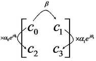
도 4는 본 발명의 일 실시예에 따라 2x2 MU-MIMO 의 프리코드 행렬에 적용되는 계수 산출 과정을 설명하는 도면이다. 도시된 실시예에 있어서 cn 을 구하는 순서는 먼저 행간 곱셈 인수를 곱하고 다음으로 열 간 곱셈 인수를 곱하는 과정으로 구헌된다. 곱셈 인수 값은 채널 파라메터에 대해 확정형 해답(closed-form solution)으로 구현되어 있어 낮은 하드웨어 복잡도로 빠르게 프리코드 행렬(precode matrix) 값이 계산된다.4 is a diagram illustrating a coefficient calculation process applied to a precode matrix of 2x2 MU-MIMO according to an embodiment of the present invention. In the illustrated embodiment, cn is obtained by first multiplying the row multiplication factor and then multiplying the column multiplication factor. The multiplication factor value is implemented as a closed-form solution for the channel parameters, allowing fast precode matrix values to be calculated with low hardware complexity.
도 4에 의해, 전송 SINR은 다음과 같은 삼각함수로 정의된다.4, the transmission SINR is defined by the following trigonometric function.


위 수식은 αn, θn 에 대해 미분 가능한 식이며, αn, θn 에 대해 각각 편미분하여 그 식의 최대값을 구할 수 있다.The above formula is the partial derivative for each possible differential an expression, αn, θn for αn, θn can be determined a maximum value of the expression.
도 4에서 각 들은 다음과 같은 확정형(closed-form)으로 주어진다.In FIG. 4, the angles are given in closed-form form as follows.

전송 SINR을 각각 에 대해 편미분하면 전송 SINR을 최대화하는 αn, θn 은 다음과 같다.A partial differential of the transmission SINRs for each of αn and θn which maximizes the transmission SINR is as follows.


여기서 φ(c)는 복소수 c의 위상이다.Where φ (c) is the phase of the complex number c.
또 정의에 의해 c1=βc0이며,


이 된다.Becomes
전 과정을 거쳐 프리코딩부(100)는 다음과 같이 설계된다.Through the whole process, the


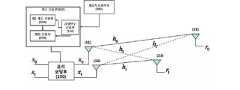
도 5는 본 발명의 일 실시예에 따른 프리코딩장치(100)를 포함하는 다중 사용자, 다중 안테나 무선 송수신 시스템을 보다 자세히 도시한다. 도시된 바와 같이, 다중 수신 단말기를 위한 다중 안테나 무선 송출 장치는 송신측 안테나와 수신 측 안테나 간의 무선 전송 채널의 특성 값을 획득하는 채널특성획득부(300)와, 신호 전송 측에서 전송 신호에 의한 간섭 및 잡음의 강도에 대한 전송 신호의 수신단 수신 전력의 비율을 최대화하는 계수 값들을 상기 전송 채널 특성 계수의 함수로 구하는 계수산출부(500)와, 상기 계수 산출부(500)에서 구해진 행렬로 입력 신호를 곱해서 출력하는 프리코딩부(100)를 포함한다.5 illustrates in more detail a multi-user, multi-antenna wireless transmit / receive system including a
도시된 실시예에 있어서, 계수 산출부(500)는 열간, 행간 곱셈 인수를 계산하는 곱셈인수(multiplication factor) 산출부(510)와, 제 1 계수를 상기 전송 채널 특성 계수의 함수로 구하는 제 1 계수 산출부(530), 상기 제 1 계수에 열간, 행간 곱셈 인수를 곱하고 그 결과값에 열간, 행간 곱셈 인수 중 하나를 곱하여 나머지 계수들을 구하는 행렬 산출부(550)를 포함한다.In the illustrated embodiment, the coefficient calculating unit 500 includes a multiplication
채널특성획득부(300)는 각 기지국의 송출단에서 셀 내 존재하는 수신 단말기들과의 통신을 통해 빈번한 주기로 채널 특성 파라메터를 획득한다. 곱셈인수 산출부(510)는 도 4의 행간, 열간 곱셈 인수들을 구한다. 제1 계수 산출부(530)는 본 실시예에 있어서, 4개의 행렬 값 중 c0를 구한다. 행렬 산출부(550)는 구해진 c0 값에 행간, 열간 곱셈인수를 곱하여 나머지 행렬 값들을 계산한다.The channel characteristic acquisition unit 300 acquires channel characteristic parameters at frequent intervals through communication with receiving terminals existing in a cell at the transmitting end of each base station. The multiplication
프리코딩부(100)는 구해진 프리코딩 행렬로 입력 신호를 처리하여 송출단으로 송출한다.The
이상에서 본 발명은 첨부된 도면을 참조하여 기술되는 바람직한 실시예를 중 심으로 설명되었지만, 이에 한정되는 것은 아니다. 예를 들어 실시예는 2개의 전송 안테나를 사용하고 2명의 사용자에게 동시 전송하는 MIMO 시스템을 중심으로 설명되었으나, 본 발명은 이에 한정되는 것이 아니다. 당업자라면 본 명세서에 기재된 전송 SINR의 개념을 이용하여 N개의 전송 안테나를 사용하여 1~N 명의 사용자에게 동시에 신호를 전송하는 일반적인 형태의 MIMO system에 사용하기 위한 프리코더 또한 동일한 방식으로 쉽게 구현할 수 있다. 따라서 본 발명은 기재된 실시예로부터 자명하게 도출되는 변형들을 포괄하도록 의도된 첨부된 특허청구범위에 의해 해석되어져야 한다.The present invention has been described above with reference to the preferred embodiments described with reference to the accompanying drawings, but is not limited thereto. For example, the embodiment has been described based on a MIMO system using two transmission antennas and simultaneously transmitting to two users, but the present invention is not limited thereto. One of ordinary skill in the art can easily implement a precoder for use in a general-purpose MIMO system that transmits signals to 1 to N users simultaneously using N transmit antennas using the concept of transmit SINR described herein. . Accordingly, the invention should be construed by the appended claims, which are intended to cover modifications apparently derived from the described embodiments.
도 1은 두 개의 전송 안테나를 사용하여 동시에 두 사용자에게 정보를 전달하는 MIMO 시스템의 일 예를 개략적으로 도시한다.1 schematically illustrates an example of a MIMO system using two transmit antennas to simultaneously transmit information to two users.
도 2는 빔 성형(beam forming)을 통해 두 사용자에게 동시에 정보를 전달하는 일 예를 도시한다.2 illustrates an example of simultaneously transmitting information to two users through beam forming.
도 3은 본 발명의 일 실시예에 따른 프리코딩장치(100)를 포함하는 다중 사용자, 다중 안테나 무선 송수신 시스템을 개략적으로 도시한다.3 schematically illustrates a multi-user, multi-antenna wireless transmission / reception system including a
도 4는 본 발명의 일 실시예에 따라 2x2 MU-MIMO 의 프리코드 행렬에 적용되는 계수 산출 과정을 설명하는 도면이다.4 is a diagram illustrating a coefficient calculation process applied to a precode matrix of 2x2 MU-MIMO according to an embodiment of the present invention.
도 5는 본 발명의 일 실시예에 따른 프리코딩장치(100)를 포함하는 다중 사용자, 다중 안테나 무선 송수신 시스템을 보다 자세히 도시한다.5 illustrates in more detail a multi-user, multi-antenna wireless transmit / receive system including a
Claims (6)
Translated fromKorean
Priority Applications (6)
| Application Number | Priority Date | Filing Date | Title |
|---|---|---|---|
| KR1020090022358AKR101055573B1 (en) | 2009-03-16 | 2009-03-16 | Precoding Device in Multi-User, Multi-antenna Radio Transmission System |
| US12/723,260US20100232536A1 (en) | 2009-03-16 | 2010-03-12 | Precoding apparatus for multi-user, multi-antenna, wireless transmission system |
| PCT/KR2010/001626WO2010107233A2 (en) | 2009-03-16 | 2010-03-16 | Precoding apparatus for multi-user, multi-antenna, wireless transmission system |
| JP2012500714AJP2012521140A (en) | 2009-03-16 | 2010-03-16 | Precoding device in multi-user multi-antenna wireless transmission system |
| CN2010800113014ACN102349241A (en) | 2009-03-16 | 2010-03-16 | Precoding apparatus for multi-user, multi-antenna, wireless transmission system |
| EP10753683AEP2409418A2 (en) | 2009-03-16 | 2010-03-16 | Precoding apparatus for multi-user, multi-antenna, wireless transmission system |
Applications Claiming Priority (1)
| Application Number | Priority Date | Filing Date | Title |
|---|---|---|---|
| KR1020090022358AKR101055573B1 (en) | 2009-03-16 | 2009-03-16 | Precoding Device in Multi-User, Multi-antenna Radio Transmission System |
Publications (2)
| Publication Number | Publication Date |
|---|---|
| KR20100104150A KR20100104150A (en) | 2010-09-29 |
| KR101055573B1true KR101055573B1 (en) | 2011-08-08 |
Family
ID=42730702
Family Applications (1)
| Application Number | Title | Priority Date | Filing Date |
|---|---|---|---|
| KR1020090022358AActiveKR101055573B1 (en) | 2009-03-16 | 2009-03-16 | Precoding Device in Multi-User, Multi-antenna Radio Transmission System |
Country Status (6)
| Country | Link |
|---|---|
| US (1) | US20100232536A1 (en) |
| EP (1) | EP2409418A2 (en) |
| JP (1) | JP2012521140A (en) |
| KR (1) | KR101055573B1 (en) |
| CN (1) | CN102349241A (en) |
| WO (1) | WO2010107233A2 (en) |
Families Citing this family (4)
| Publication number | Priority date | Publication date | Assignee | Title |
|---|---|---|---|---|
| US9008220B2 (en) | 2010-12-07 | 2015-04-14 | Ceragon Networks Ltd. | Frequency reuse in wireless point-to-point communication systems |
| EP2464072B1 (en)* | 2010-12-07 | 2015-09-30 | Ceragon Networks LTD. | Frequency reuse in wireless point-to-point communication systems |
| CN111566941B (en) | 2018-01-08 | 2021-10-22 | 英国电讯有限公司 | Method and apparatus for transmitting data in a communication system, machine-readable storage medium |
| GB2601566A (en)* | 2020-12-07 | 2022-06-08 | British Telecomm | Improvements to MIMO systems |
Citations (3)
| Publication number | Priority date | Publication date | Assignee | Title |
|---|---|---|---|---|
| WO2008021008A2 (en) | 2006-08-07 | 2008-02-21 | Interdigital Technology Corporation | Method, apparatus and system for implementing multi-user virtual multiple-input multiple-output |
| KR20080059672A (en)* | 2005-10-27 | 2008-06-30 | 퀄컴 인코포레이티드 | Pre-coding method and apparatus for MIO system |
| KR20090023879A (en)* | 2007-09-03 | 2009-03-06 | 삼성전자주식회사 | Signal Processing Apparatus and Method for Interference Cancellation in Multi-user Multi-input / Output Wireless Communication Systems |
Family Cites Families (6)
| Publication number | Priority date | Publication date | Assignee | Title |
|---|---|---|---|---|
| US6317466B1 (en)* | 1998-04-15 | 2001-11-13 | Lucent Technologies Inc. | Wireless communications system having a space-time architecture employing multi-element antennas at both the transmitter and receiver |
| US6771706B2 (en)* | 2001-03-23 | 2004-08-03 | Qualcomm Incorporated | Method and apparatus for utilizing channel state information in a wireless communication system |
| KR100980647B1 (en)* | 2007-07-05 | 2010-09-07 | 삼성전자주식회사 | Interference Cancellation Device and Method in Multi-antenna System |
| KR101087813B1 (en)* | 2007-08-31 | 2011-11-29 | 후지쯔 가부시끼가이샤 | Wireless communication system and wireless communication method |
| US8064849B2 (en)* | 2008-02-07 | 2011-11-22 | Telefonaktiebolaget Lm Ericsson (Publ) | Precoding for multiple anntennas |
| US8098750B2 (en)* | 2008-07-10 | 2012-01-17 | Infineon Technologies Ag | Method and device for transmitting a plurality of data symbols |
- 2009
- 2009-03-16KRKR1020090022358Apatent/KR101055573B1/enactiveActive
- 2010
- 2010-03-12USUS12/723,260patent/US20100232536A1/ennot_activeAbandoned
- 2010-03-16EPEP10753683Apatent/EP2409418A2/ennot_activeWithdrawn
- 2010-03-16JPJP2012500714Apatent/JP2012521140A/ennot_activeWithdrawn
- 2010-03-16CNCN2010800113014Apatent/CN102349241A/enactivePending
- 2010-03-16WOPCT/KR2010/001626patent/WO2010107233A2/enactiveApplication Filing
Patent Citations (3)
| Publication number | Priority date | Publication date | Assignee | Title |
|---|---|---|---|---|
| KR20080059672A (en)* | 2005-10-27 | 2008-06-30 | 퀄컴 인코포레이티드 | Pre-coding method and apparatus for MIO system |
| WO2008021008A2 (en) | 2006-08-07 | 2008-02-21 | Interdigital Technology Corporation | Method, apparatus and system for implementing multi-user virtual multiple-input multiple-output |
| KR20090023879A (en)* | 2007-09-03 | 2009-03-06 | 삼성전자주식회사 | Signal Processing Apparatus and Method for Interference Cancellation in Multi-user Multi-input / Output Wireless Communication Systems |
Also Published As
| Publication number | Publication date |
|---|---|
| WO2010107233A3 (en) | 2010-11-18 |
| WO2010107233A2 (en) | 2010-09-23 |
| US20100232536A1 (en) | 2010-09-16 |
| KR20100104150A (en) | 2010-09-29 |
| CN102349241A (en) | 2012-02-08 |
| JP2012521140A (en) | 2012-09-10 |
| EP2409418A2 (en) | 2012-01-25 |
Similar Documents
| Publication | Publication Date | Title |
|---|---|---|
| CN105940616B (en) | Multi-stage beamforming for multi-antenna communication systems | |
| KR101631784B1 (en) | Method and arrangement in a wireless communication system | |
| US8619886B2 (en) | Method and system for mixed analog/digital beamforming in wireless communication systems | |
| KR102508858B1 (en) | Method and Apparatus for Transmitting Diversity | |
| US9887757B2 (en) | Method and apparatus for efficient channel state information dissemination for MU-MIMO transmission schemes based on outdated channel state information | |
| EP2580898B1 (en) | MIMO transmission and reception system with decentralized channel estimation and precoding | |
| KR20100053417A (en) | Method of signals transmission and signals reception in the multi-imput multi-output systems | |
| EP1502366A1 (en) | Space-time transmit diversity (sttd) for multiple antennas in radio communications | |
| JP2011130438A (en) | Transmission method for multi-user mimo in radio communication system, base station and user terminal | |
| CN103098385A (en) | Wireless communication control method, wireless communication system, wireless base station and mobile terminal | |
| CN105519029B (en) | Ofdm communication system and signal transmit-receive method and device | |
| CN101227217A (en) | Random beamforming method and system based on multi-antenna receiver | |
| WO2015112883A1 (en) | System and method for early termination in iterative null-space directed singular value decomposition for mimo | |
| KR20150134520A (en) | Apparatus for processing transmission/reception signal for interference alignment in a mu-mimo interference broadcasting channel and method thereof | |
| KR20030078663A (en) | A closed loop multiple antenna system | |
| KR101055573B1 (en) | Precoding Device in Multi-User, Multi-antenna Radio Transmission System | |
| KR101422026B1 (en) | A method for transmitting/receiving signal in a Multiple Input Multiple Output system | |
| Tang et al. | Downlink path-based precoding in FDD massive MIMO systems without CSI feedback | |
| Kapinas et al. | A universal MIMO approach for 3GPP wireless standards | |
| KR20110006121A (en) | A system for selecting a transmit antenna and a user when detecting maximum likelihood in a multi-user spatial multiplexing system | |
| KR101100211B1 (en) | Signal Transmission Method Using Multiple Antennas | |
| Higashino et al. | Link quality based MIMO antenna selection in RoF ubiquitous antenna | |
| Komulainen et al. | CSI acquisition concepts for advanced antenna schemes in the WINNER+ project | |
| EP2939350B1 (en) | Method and apparatus for multi-user multiple-input and multiple-output precoding | |
| WO2012083750A1 (en) | Method, device and system for implementing microwave multiple-input multiple-output |
Legal Events
| Date | Code | Title | Description |
|---|---|---|---|
| A201 | Request for examination | ||
| PA0109 | Patent application | Patent event code:PA01091R01D Comment text:Patent Application Patent event date:20090316 | |
| PA0201 | Request for examination | ||
| N231 | Notification of change of applicant | ||
| PN2301 | Change of applicant | Patent event date:20100401 Comment text:Notification of Change of Applicant Patent event code:PN23011R01D | |
| PG1501 | Laying open of application | ||
| E902 | Notification of reason for refusal | ||
| PE0902 | Notice of grounds for rejection | Comment text:Notification of reason for refusal Patent event date:20101026 Patent event code:PE09021S01D | |
| E701 | Decision to grant or registration of patent right | ||
| PE0701 | Decision of registration | Patent event code:PE07011S01D Comment text:Decision to Grant Registration Patent event date:20110523 | |
| GRNT | Written decision to grant | ||
| PR0701 | Registration of establishment | Comment text:Registration of Establishment Patent event date:20110802 Patent event code:PR07011E01D | |
| PR1002 | Payment of registration fee | Payment date:20110802 End annual number:3 Start annual number:1 | |
| PG1601 | Publication of registration | ||
| FPAY | Annual fee payment | Payment date:20160801 Year of fee payment:6 | |
| PR1001 | Payment of annual fee | Payment date:20160801 Start annual number:6 End annual number:6 | |
| FPAY | Annual fee payment | Payment date:20180129 Year of fee payment:7 | |
| PR1001 | Payment of annual fee | Payment date:20180129 Start annual number:7 End annual number:7 | |
| FPAY | Annual fee payment | Payment date:20190128 Year of fee payment:8 | |
| PR1001 | Payment of annual fee | Payment date:20190128 Start annual number:8 End annual number:8 | |
| PR1001 | Payment of annual fee | Payment date:20200608 Start annual number:10 End annual number:10 | |
| PR1001 | Payment of annual fee | Payment date:20210607 Start annual number:11 End annual number:11 | |
| PR1001 | Payment of annual fee | Payment date:20220621 Start annual number:12 End annual number:12 | |
| PR1001 | Payment of annual fee | Payment date:20230801 Start annual number:13 End annual number:13 |