KR101047090B1 - An apparatus for supplying a substrate to a processing tool, a method of delivering a substrate carrier, a method of delivering a substrate carrier to a substrate loading station, a method of operating a substrate carrier handler, a computer program product configured to control the separation of the substrate carrier from the substrate carrier transporter, And how to deliver the substrate - Google Patents
An apparatus for supplying a substrate to a processing tool, a method of delivering a substrate carrier, a method of delivering a substrate carrier to a substrate loading station, a method of operating a substrate carrier handler, a computer program product configured to control the separation of the substrate carrier from the substrate carrier transporter, And how to deliver the substrateDownload PDFInfo
- Publication number
- KR101047090B1 KR101047090B1KR1020030060776AKR20030060776AKR101047090B1KR 101047090 B1KR101047090 B1KR 101047090B1KR 1020030060776 AKR1020030060776 AKR 1020030060776AKR 20030060776 AKR20030060776 AKR 20030060776AKR 101047090 B1KR101047090 B1KR 101047090B1
- Authority
- KR
- South Korea
- Prior art keywords
- substrate carrier
- substrate
- end effector
- handler
- conveyor
- Prior art date
- Legal status (The legal status is an assumption and is not a legal conclusion. Google has not performed a legal analysis and makes no representation as to the accuracy of the status listed.)
- Expired - Fee Related
Links
Images


Classifications
- B—PERFORMING OPERATIONS; TRANSPORTING
- B65—CONVEYING; PACKING; STORING; HANDLING THIN OR FILAMENTARY MATERIAL
- B65G—TRANSPORT OR STORAGE DEVICES, e.g. CONVEYORS FOR LOADING OR TIPPING, SHOP CONVEYOR SYSTEMS OR PNEUMATIC TUBE CONVEYORS
- B65G49/00—Conveying systems characterised by their application for specified purposes not otherwise provided for
- B65G49/05—Conveying systems characterised by their application for specified purposes not otherwise provided for for fragile or damageable materials or articles
- B65G49/07—Conveying systems characterised by their application for specified purposes not otherwise provided for for fragile or damageable materials or articles for semiconductor wafers Not used, see H01L21/677
- B—PERFORMING OPERATIONS; TRANSPORTING
- B65—CONVEYING; PACKING; STORING; HANDLING THIN OR FILAMENTARY MATERIAL
- B65G—TRANSPORT OR STORAGE DEVICES, e.g. CONVEYORS FOR LOADING OR TIPPING, SHOP CONVEYOR SYSTEMS OR PNEUMATIC TUBE CONVEYORS
- B65G37/00—Combinations of mechanical conveyors of the same kind, or of different kinds, of interest apart from their application in particular machines or use in particular manufacturing processes
- B65G37/02—Flow-sheets for conveyor combinations in warehouses, magazines or workshops
- B—PERFORMING OPERATIONS; TRANSPORTING
- B65—CONVEYING; PACKING; STORING; HANDLING THIN OR FILAMENTARY MATERIAL
- B65G—TRANSPORT OR STORAGE DEVICES, e.g. CONVEYORS FOR LOADING OR TIPPING, SHOP CONVEYOR SYSTEMS OR PNEUMATIC TUBE CONVEYORS
- B65G47/00—Article or material-handling devices associated with conveyors; Methods employing such devices
- B65G47/52—Devices for transferring articles or materials between conveyors i.e. discharging or feeding devices
- B65G47/60—Devices for transferring articles or materials between conveyors i.e. discharging or feeding devices to or from conveyors of the suspended, e.g. trolley, type
- B65G47/61—Devices for transferring articles or materials between conveyors i.e. discharging or feeding devices to or from conveyors of the suspended, e.g. trolley, type for articles
- H—ELECTRICITY
- H01—ELECTRIC ELEMENTS
- H01L—SEMICONDUCTOR DEVICES NOT COVERED BY CLASS H10
- H01L21/00—Processes or apparatus adapted for the manufacture or treatment of semiconductor or solid state devices or of parts thereof
- H01L21/67—Apparatus specially adapted for handling semiconductor or electric solid state devices during manufacture or treatment thereof; Apparatus specially adapted for handling wafers during manufacture or treatment of semiconductor or electric solid state devices or components ; Apparatus not specifically provided for elsewhere
- H01L21/677—Apparatus specially adapted for handling semiconductor or electric solid state devices during manufacture or treatment thereof; Apparatus specially adapted for handling wafers during manufacture or treatment of semiconductor or electric solid state devices or components ; Apparatus not specifically provided for elsewhere for conveying, e.g. between different workstations
- H01L21/67763—Apparatus specially adapted for handling semiconductor or electric solid state devices during manufacture or treatment thereof; Apparatus specially adapted for handling wafers during manufacture or treatment of semiconductor or electric solid state devices or components ; Apparatus not specifically provided for elsewhere for conveying, e.g. between different workstations the wafers being stored in a carrier, involving loading and unloading
- H01L21/67769—Storage means
- H—ELECTRICITY
- H01—ELECTRIC ELEMENTS
- H01L—SEMICONDUCTOR DEVICES NOT COVERED BY CLASS H10
- H01L21/00—Processes or apparatus adapted for the manufacture or treatment of semiconductor or solid state devices or of parts thereof
- H01L21/67—Apparatus specially adapted for handling semiconductor or electric solid state devices during manufacture or treatment thereof; Apparatus specially adapted for handling wafers during manufacture or treatment of semiconductor or electric solid state devices or components ; Apparatus not specifically provided for elsewhere
- H01L21/677—Apparatus specially adapted for handling semiconductor or electric solid state devices during manufacture or treatment thereof; Apparatus specially adapted for handling wafers during manufacture or treatment of semiconductor or electric solid state devices or components ; Apparatus not specifically provided for elsewhere for conveying, e.g. between different workstations
- H01L21/67763—Apparatus specially adapted for handling semiconductor or electric solid state devices during manufacture or treatment thereof; Apparatus specially adapted for handling wafers during manufacture or treatment of semiconductor or electric solid state devices or components ; Apparatus not specifically provided for elsewhere for conveying, e.g. between different workstations the wafers being stored in a carrier, involving loading and unloading
- H01L21/67775—Docking arrangements
- H—ELECTRICITY
- H01—ELECTRIC ELEMENTS
- H01L—SEMICONDUCTOR DEVICES NOT COVERED BY CLASS H10
- H01L21/00—Processes or apparatus adapted for the manufacture or treatment of semiconductor or solid state devices or of parts thereof
- H01L21/67—Apparatus specially adapted for handling semiconductor or electric solid state devices during manufacture or treatment thereof; Apparatus specially adapted for handling wafers during manufacture or treatment of semiconductor or electric solid state devices or components ; Apparatus not specifically provided for elsewhere
- H01L21/677—Apparatus specially adapted for handling semiconductor or electric solid state devices during manufacture or treatment thereof; Apparatus specially adapted for handling wafers during manufacture or treatment of semiconductor or electric solid state devices or components ; Apparatus not specifically provided for elsewhere for conveying, e.g. between different workstations
- H01L21/67763—Apparatus specially adapted for handling semiconductor or electric solid state devices during manufacture or treatment thereof; Apparatus specially adapted for handling wafers during manufacture or treatment of semiconductor or electric solid state devices or components ; Apparatus not specifically provided for elsewhere for conveying, e.g. between different workstations the wafers being stored in a carrier, involving loading and unloading
- H01L21/67778—Apparatus specially adapted for handling semiconductor or electric solid state devices during manufacture or treatment thereof; Apparatus specially adapted for handling wafers during manufacture or treatment of semiconductor or electric solid state devices or components ; Apparatus not specifically provided for elsewhere for conveying, e.g. between different workstations the wafers being stored in a carrier, involving loading and unloading involving loading and unloading of wafers
- B—PERFORMING OPERATIONS; TRANSPORTING
- B65—CONVEYING; PACKING; STORING; HANDLING THIN OR FILAMENTARY MATERIAL
- B65G—TRANSPORT OR STORAGE DEVICES, e.g. CONVEYORS FOR LOADING OR TIPPING, SHOP CONVEYOR SYSTEMS OR PNEUMATIC TUBE CONVEYORS
- B65G2201/00—Indexing codes relating to handling devices, e.g. conveyors, characterised by the type of product or load being conveyed or handled
- B65G2201/02—Articles
- B65G2201/0297—Wafer cassette
Landscapes
- Engineering & Computer Science (AREA)
- Physics & Mathematics (AREA)
- Condensed Matter Physics & Semiconductors (AREA)
- General Physics & Mathematics (AREA)
- Manufacturing & Machinery (AREA)
- Computer Hardware Design (AREA)
- Microelectronics & Electronic Packaging (AREA)
- Power Engineering (AREA)
- Mechanical Engineering (AREA)
- Container, Conveyance, Adherence, Positioning, Of Wafer (AREA)
- Intermediate Stations On Conveyors (AREA)
Abstract
Translated fromKoreanDescription
Translated fromKorean도 1은 프로세싱 툴의 통상적인 배치 및 관련 기판 캐리어의 로딩 및 저장 장치를 도시한 평면도.1 is a plan view showing a conventional arrangement of a processing tool and a loading and storage device of an associated substrate carrier.
도 2a는 본 발명에 따라 제공된 기판 로딩 스테이션의 정면도.2A is a front view of a substrate loading station provided in accordance with the present invention.
도 2b는 기판 로딩 스테이션의 제 1 센서의 예시적인 실시예를 설명하기 위한 것으로서 도 2a의 기판 로딩 스테이션의 일부를 도시한 측면도.FIG. 2B is a side view illustrating a portion of the substrate loading station of FIG. 2A for explaining an exemplary embodiment of a first sensor of the substrate loading station. FIG.
도 2c는 도 2a의 기판 로딩 스테이션의 예시적인 제 2 센서를 나타내기 위한 도 2a의 엔드 이펙터의 일부의 사시도.FIG. 2C is a perspective view of a portion of the end effector of FIG. 2A to illustrate an exemplary second sensor of the substrate loading station of FIG. 2A.
도 2d는 도 2c의 일부의 확대 사시도.2D is an enlarged perspective view of a portion of FIG. 2C.
도 2e는 캐리어 결합 부재의 일부를 감지하기 위해 위치된 제 2 센서를 도시하기 위한 도 2a의 엔드 이펙터의 일부의 사시도.FIG. 2E is a perspective view of a portion of the end effector of FIG. 2A to illustrate a second sensor positioned to sense a portion of the carrier engagement member. FIG.
도 3은 이동하는 이송기로부터 기판 캐리어를 언로딩하기 위해 본 발명에 따라 실행되는 예시적인 공정을 도시한 흐름도.3 is a flow chart illustrating an exemplary process performed in accordance with the present invention for unloading a substrate carrier from a moving conveyor.
도 4a 내지 도 4e는 도 3의 공정의 여러 단계를 도시한 측면도.4A-4E are side views illustrating various stages of the process of FIG. 3.
도 5는 이동하는 이송기로상에 기판 캐리어를 로딩하기 위해 본 발명에 따라 실행되는 예시적인 공정을 도시한 흐름도.5 is a flow diagram illustrating an exemplary process performed in accordance with the present invention for loading a substrate carrier onto a moving conveyor.
도 6a 내지 도 6e는 도 5의 공정의 여러 단계를 도시한 측면도.6A-6E are side views illustrating various stages of the process of FIG. 5.
도 7a 및 도 7b는 도 2a와 유사한 도면으로서, 본 발명의 기판 로딩 스테이션을 단순화하여 도시한 정면도.7A and 7B are views similar to those in FIG. 2A, in a simplified front view of the substrate loading station of the present invention.
도 7c 내지 도 7d는 도 4a 내지 도 4e 및 도 6a 내지 도 6e와 유사한 도면으로서, 이동하는 이송기를 단순화하여 도시한 측면도.7C-7D are views similar to FIGS. 4A-4E and 6A-6E, with simplified side views of the moving conveyor.
도 8a 내지 도 8d는 본 발명의 엔드 이펙터에 대한 예시적인 이동 프로파일을 도시한 도면.8A-8D illustrate exemplary movement profiles for the end effector of the present invention.
* 도면의 주요 부분에 대한 부호의 설명*Description of the Related Art [0002]
201 : 로딩 스테이션203 : 도킹 스테이션201: loading station 203: docking station
207 : 기판 캐리어211 : 결합 그리퍼207: substrate carrier 211: bond gripper
213 : 기판 캐리어 오프너215 : 핸들러213: substrate carrier opener 215: handler
217, 219 : 수직 가이드221 : 수평 가이드217, 219: vertical guide 221: horizontal guide
225 : 엔드 이펙터229 : 동적 핀225: End Effector 229: Dynamic Pins
231 : 이송기233, 235 : 센서231:
237 : 제어기239 : 저장 선반237
240a, 240b : 엔코더401 : 캐리어 체결 부재240a, 240b: encoder 401: carrier fastening member
402 : 플랜지402: flange
본 출원은 2002년 8월 31일자로 출원된 미국 특허 가명세서 출원 제 60/407,463 호 및 2003년 1월 27일자로 출원된 미국 특허 가명세서 출원 제 60/443,004 호를 기초로 우선권을 주장하며, 상기 두 출원의 전체를 본 명세서에서 참조로서 포함한다.This application claims priority based on U.S. Patent Alias Application No. 60 / 407,463, filed Aug. 31, 2002 and U.S. Patent Alias Application No. 60 / 443,004, filed Jan. 27, 2003, The entirety of both applications is incorporated herein by reference.
본 발명은 대략적으로 반도체 장치 제조 시스템에 관한 것이고, 특히 제조 설비내에서 기판 캐리어의 전달에 관한 것이다.The present invention relates generally to semiconductor device manufacturing systems, and more particularly to the delivery of substrate carriers in a manufacturing facility.
관련 출원에 대한 교차 참조Cross Reference to Related Applications
본 발명은 공통적으로 양도되고, 현재 계류중인 이하의 미국 특허 출원들에 관련되며, 그 출원들은 본 명세서에서 전체가 참조로 포함된다.The present invention relates to commonly assigned, below pending, US patent applications, which are incorporated by reference in their entirety herein.
2002년 8월 31일자로 출원되고 명칭이 "웨이퍼 캐리어 이용 시스템(System For Transporting Wafer Carriers)"인 미국 가명세서 출원 제 60/407,451(서류 번호 제 6900/L);US Provisional Application No. 60 / 407,451, filed August 31, 2002, entitled "System For Transporting Wafer Carriers" (Document No. 6900 / L);
2002년 8월 31일자로 출원되고 명칭이 "웨이퍼 도어를 개방/폐쇄 작동시키기 위해 웨이퍼 캐리어 이동을 이용하는 방법 및 장치(Method and Apparatus for Using Wafer Carrier Movement to Actuate Wafer Carrier Door Opening/Closing)"인 미국 가명세서 출원 제 60/407,339(서류 번호 제 6976/L);United States, filed August 31, 2002 and entitled "Method and Apparatus for Using Wafer Carrier Movement to Actuate Wafer Carrier Door Opening / Closing" Alias Specification No. 60 / 407,339 (Document No. 6976 / L);
2002년 8월 31일자로 출원되고 명칭이 "웨이퍼 캐리어 전달 시스템으로부터 웨이퍼 캐리어를 언로딩하기 위한 방법 및 장치(Method and Apparatus for Unloading Wafer Carriers from Wafer Carrier Transport System)"인 미국 가명세 서 출원 제 60/407,474(서류 번호 제 7024/L);US Provisional Application No. 60, filed August 31, 2002, entitled “Method and Apparatus for Unloading Wafer Carriers from Wafer Carrier Transport System” / 407,474 (Document No. 7024 / L);
2002년 8월 31일자로 출원되고 명칭이 "처리 장치로 웨이퍼를 공급하기 위한 방법 및 장치(Method and Apparatus for Supplying Wafers to a Processing Tool)"인 미국 가명세서 출원 제 60/407,336(서류 번호 제 7096/L);U.S. Provisional Application No. 60 / 407,336, filed August 31, 2002, entitled "Method and Apparatus for Supplying Wafers to a Processing Tool" (Document No. 7096). / L);
2002년 8월 31일자로 출원되고 명칭이 "수직 및 수평 배향위치 사이에서 웨이퍼 캐리어를 재배향시키기 위한 기구를 가지는 엔드 이펙터(End Effector Having Mechanism For Reorienting A Wafer Carrier Between Vertical And Horizontal Orientations)"인 미국 가명세서 출원 제 60/407,452(서류 번호 제 7097/L);United States, filed August 31, 2002, entitled "End Effector Having Mechanism For Reorienting A Wafer Carrier Between Vertical And Horizontal Orientations" Alias Specification No. 60 / 407,452 (Document No. 7097 / L);
2002년 8월 31일자로 출원되고 명칭이 "도킹 스테이션에 도킹 그리퍼를 가지는 웨이퍼 로딩 스테이션(Wafer Loading Station with Docking Grippers at Docking Stations)"인 미국 가명세서 출원 제 60/407,337(서류 번호 제 7099/L);U.S. Provisional Application No. 60 / 407,337, filed Aug. 31, 2002, entitled "Wafer Loading Station with Docking Grippers at Docking Stations" (Document No. 7099 / L). );
2002년 8월 31일자로 출원되고 명칭이 "도어 래칭 및 웨이퍼 크램핑 기구를 구비한 웨이퍼 캐리어(Wafer Carrier having Door Latching and Wafer Clamping Mechanisms)"인 미국 가명세서 출원 제 60/407,340(서류 번호 제 7156/L);U.S. Provisional Application No. 60 / 407,340, filed Aug. 31, 2002, entitled "Wafer Carrier having Door Latching and Wafer Clamping Mechanisms" (Document No. 7156). / L);
2003년 1월 27일자로 출원되고 명칭이 "웨이퍼 캐리어 전달 방법 및 장치(Method and Apparatus for Transporting Wafer Carriers)"인 미국 가명세서 출원 제 60/443,087(서류 번호 제 7163/L);US Provisional Application No. 60 / 443,087, filed January 27, 2003, entitled "Method and Apparatus for Transporting Wafer Carriers" (Document No. 7163 / L);
2003년 1월 27일자로 출원되고 명칭이 "오버헤드 전달 플랜지 및 웨이퍼 캐리어 현수용 지지체(Overhead Transfer Flange and Support for Suspending Wafer Carrier)"인 미국 가명세서 출원 제 60/443,153(서류 번호 제 8092/L);U.S. Provisional Application No. 60 / 443,153, filed Jan. 27, 2003, entitled "Overhead Transfer Flange and Support for Suspending Wafer Carrier" (Document No. 8092 / L). );
2003년 1월 27일자로 출원되고 명칭이 "처리 공구 사이에서 웨이퍼 캐리어를 전달하기 위한 시스템 및 방법(System and Method for Transferring Wafer Carriers Between Processing Tools)"인 미국 가명세서 출원 제 60/443,001(서류 번호 제 8201/L); 및U.S. Provisional Application No. 60 / 443,001, filed Jan. 27, 2003, entitled "System and Method for Transferring Wafer Carriers Between Processing Tools." 8201 / L); And
2003년 1월 27일자로 출원되고 명칭이 "웨이퍼 캐리어 저장과 로딩을 위한 장치 및 방법(Apparatus and Method for Stroring and Loading Wafer Carriers)"인 미국 가명세서 출원 제 60/443,115(서류 번호 제 8202/L);US Provisional Application No. 60 / 443,115, filed Jan. 27, 2003, entitled "Apparatus and Method for Stroring and Loading Wafer Carriers" (Document No. 8202 / L). );
통상적으로, 반도체 장치의 제조는 실리콘 기판, 유리 플레이트 등과 같은 기판에 대해 일련의 공정을 수행하는 것을 포함한다(그러한 기판은 패턴화되었던지 또는 아니던지에 관계 없이 웨이퍼라고 지칭될 수 있을 것이다). 이러한 단계들은 연마, 증착, 에칭, 포토리소그래피, 열처리 등을 포함한다. 일반적으로, 수 많은 상이한 처리 단계들이 하나의 처리 시스템 또는 다수의 처리 챔버를 포함하는 "장치"내에서 실시될 것이다. 그러나, 일반적으로, 제조 설비내의 다른 처리 위치에서 다른 처리를 할 필요가 있을 것이고, 그에 따라 제조 설비내에서 하나의 처리 위치로부터 다른 처리 위치로 기판을 전달할 필요가 있다. 제조되는 반도체 장치의 타입에 따라, 제조 설비내에서 수 많은 상이한 처리 위치에서 비교적 많은 수의 처리 단계들을 실시할 것이다.Typically, fabrication of semiconductor devices involves performing a series of processes on substrates such as silicon substrates, glass plates, and the like (such substrates may be referred to as wafers, whether patterned or not). These steps include polishing, deposition, etching, photolithography, heat treatment, and the like. In general, many different processing steps will be performed in an "apparatus" comprising one processing system or multiple processing chambers. In general, however, there will be a need to perform different treatments at different processing locations within the manufacturing facility, and therefore, there is a need to transfer substrates from one processing location to another processing location within the manufacturing facility. Depending on the type of semiconductor device being manufactured, a relatively large number of processing steps will be performed at many different processing locations within the manufacturing facility.
통상적으로, 밀봉된 포드(pod), 카세트, 컨테이너 등과 같은 기판 캐리어내에서 기판이 하나의 처리 위치에서 다른 처리 위치로 전달된다. 또한, 통상적으로, 자동화된 안내 차량, 오버헤드(overhead) 전달 시스템, 기판 캐리어 취급 로봇 등과 같은 자동화된 기판 캐리어 전달 장치를 이용하여 기판 캐리어를 제조 설비내의 하나의 위치로부터 다른 위치로 이동시키거나 또는 기판 캐리어를 기판 캐리어 전달 장치내외로 전달한다.Typically, substrates are transferred from one processing location to another within a substrate carrier, such as a sealed pod, cassette, container, or the like. Also, typically, an automated substrate carrier delivery device, such as an automated guided vehicle, an overhead delivery system, a substrate carrier handling robot, etc., is used to move the substrate carrier from one location to another within a manufacturing facility, or The substrate carrier is delivered into and out of the substrate carrier delivery device.
각각의 기판에 대해, 최초의 기판의 형성 또는 수령으로부터 최종 기판에서 반도체 장치를 절단해내기 까지의 전체 제조 공정은 주단위 또는 월단위로 측정되는 경과 시간을 필요로 할 것이다. 그에 따라, 통상적인 제조 설비에서, 임의의 주어진 시간에 많은 수의 기판이 재공품(在工品; work in process; WIP)으로서 존재할 것이다. WIP로서 제조 설비내에 존재하는 기판은 많은 운전 자본의 투자를 나타내며, 이는 기판당 제조 비용을 상승시킨다. 따라서, 제조 설비에서, 주어진 기판 처리량에 대한 WIP량을 감소시키는 것이 바람직하다. 이를 위해서는, 각각의 기판을 처리하기 위한 전체 경과 시간 이 감소되어야 한다.For each substrate, the entire manufacturing process from the formation or receipt of the first substrate to the cutting off of the semiconductor device from the final substrate will require elapsed time, measured weekly or monthly. Thus, in a typical manufacturing facility, a large number of substrates will be present as work in process (WIP) at any given time. Substrates present in manufacturing facilities as WIPs represent a significant investment of operating capital, which increases manufacturing costs per substrate. Therefore, in manufacturing facilities, it is desirable to reduce the amount of WIP for a given substrate throughput. For this purpose, the total elapsed time for processing each substrate must be reduced.
본 발명의 제 1 특징에서, 기판을 처리 장치로 공급하기 위한 제 1 장치가 제공된다. 제 1 장치는 기판 캐리어를 처리 장치의 제 1 로딩 포트(port)로 전달하기 위한 기판 캐리어 핸들러를 포함한다. 기판 캐리어 핸들러는 기판 캐리어를 지지하는 엔드 이펙터(end effector)를 포함한다. 제어부가 기판 캐리어 핸들러에 연결되며, 기판 캐리어가 이동되고 기판 캐리어 이송기에 의해 전달되는 동안 기판 캐리어 핸들러의 엔드 이펙터가 기판 캐리어 이송기로부터 기판 캐리어를 분리시키도록 기판 캐리어 핸들러를 제어한다.In a first aspect of the invention, a first apparatus for supplying a substrate to a processing apparatus is provided. The first apparatus includes a substrate carrier handler for delivering the substrate carrier to a first loading port of the processing apparatus. The substrate carrier handler includes an end effector that supports the substrate carrier. A control unit is connected to the substrate carrier handler, and the end effector of the substrate carrier handler controls the substrate carrier handler to separate the substrate carrier from the substrate carrier transporter while the substrate carrier is moved and delivered by the substrate carrier transporter.
본 발명의 제 2 특징에서, 기판을 처리 장치로 공급하기 위한 제 2 장치가 제공된다. 제 2 장치는 기판 캐리어를 처리 장치의 제 1 로딩 포트로 전달하기 위한 기판 캐리어 핸들러를 포함한다. 기판 캐리어 핸들러는 (1) 수직 가이드; (2) 상기 수직 가이드에 연결된 수평 가이드; 및 (3) 기판 캐리어를 지지하고 수직 가이드에 대해 수직방향으로 이동시키고 수평 가이드에 대해 수평방향으로 이동시키는 엔드 이펙터를 포함한다. 제어부가 기판 캐리어 핸들러에 연결되며, 기판 캐리어 핸들러의 엔드 이펙터가 기판 캐리어 핸들러에 인접하여 위치된 기판 캐리어 이송기로부터 기판 캐리어를 분리시키도록 기판 캐리어 핸들러를 제어한다.In a second aspect of the invention, a second apparatus for supplying a substrate to a processing apparatus is provided. The second apparatus includes a substrate carrier handler for delivering the substrate carrier to the first loading port of the processing apparatus. The substrate carrier handler includes (1) a vertical guide; (2) a horizontal guide connected to the vertical guide; And (3) an end effector that supports the substrate carrier, moves vertically with respect to the vertical guide, and moves horizontally with respect to the horizontal guide. A control is coupled to the substrate carrier handler and controls the substrate carrier handler such that an end effector of the substrate carrier handler separates the substrate carrier from the substrate carrier transporter located adjacent to the substrate carrier handler.
본 발명의 제 3 특징에서, 기판을 처리 장치로 공급하기 위한 제 3 장치가 제공된다. 제 3 장치는 기판 캐리어를 처리 장치의 제 1 로딩 포트로 전달하기 위한 기판 캐리어 핸들러를 포함한다. 기판 캐리어 핸들러는 기판 캐리어를 지지하는 엔드 이펙터를 포함한다. 제어부가 기판 캐리어 핸들러에 연결되고 기판 캐리어 핸들러를 제어하여, (1) 기판 캐리어가 기판 캐리어 이송기에 의해 시동됨에 따른 기판 캐리어의 이동에 실질적으로 일치되도록 기판 캐리어 핸들러의 엔드 이펙터를 수평방향을 따라 이동시키고; (2) 엔드 이펙터를 상승시켜 기판 캐리어와 결합시키고 그 기판 캐리어를 기판 캐리어 이송기로부터 분리시키며; 그리고 (3) 기판 캐리어를 제 1 로딩 포트로 전달시킨다. 본 발명의 이러한 특징들 및 기타 특징들에 따른 시스템, 방법 및 컴퓨터 프로그램 제품과 같은, 수많은 다른 특징들이 제공된다.In a third aspect of the invention, a third apparatus for supplying a substrate to a processing apparatus is provided. The third apparatus includes a substrate carrier handler for delivering the substrate carrier to the first loading port of the processing apparatus. The substrate carrier handler includes an end effector that supports the substrate carrier. The control unit is connected to the substrate carrier handler and controls the substrate carrier handler to (1) move the end effector of the substrate carrier handler along the horizontal direction to substantially match the movement of the substrate carrier as the substrate carrier is started by the substrate carrier conveyor. To; (2) raise the end effector to engage the substrate carrier and separate the substrate carrier from the substrate carrier transporter; And (3) transfer the substrate carrier to the first loading port. Numerous other features are provided, such as systems, methods, and computer program products according to these and other features of the present invention.
본 발명의 방법 및 장치는 교환중에 이동하는 이송기와 기판 캐리어를 교체하기 위한 효과적이고 신뢰할 수 있는 구성을 제공한다. 본 발명의 방법 및 장치 는, 통상적으로 기판 로딩 스테이션의 일부로서 제공되는 기판 캐리어 핸들러가 본 발명에 따라 작동되어 이송기가 이동하는 동안 이송기와 기판 캐리어를 교환하기 위한 추가적인 장비를 필요로 하지 않는다는 점에서 유리하다.The method and apparatus of the present invention provide an effective and reliable configuration for replacing the substrate carrier and the conveyor moving during the exchange. The method and apparatus of the present invention, in that the substrate carrier handler, which is typically provided as part of the substrate loading station, is operated in accordance with the present invention and does not require additional equipment to exchange the substrate carrier with the conveyor while the conveyor is moving. It is advantageous.
본 발명의 다른 특징들은 이하의 예시적인 실시예, 청구범위 및 첨부 도면에 대한 상세한 설명으로부터 보다 분명히 이해될 수 있을 것이다.Other features of the present invention will become more apparent from the following detailed description of exemplary embodiments, claims, and the accompanying drawings.
2002년 8월 31일자로 출원되고 명칭이 "웨이퍼 캐리어 전달용 시스템(System For Transporting Semiconductor Wafer Carriers)"인 상기 미국 가명세서 출원 제 60/407,451(서류 번호 제 6900)에는 제조 설비의 작동중에 계속적으로 이동하는 기판 캐리어용 이송기를 포함하는 기판 캐리어 전달 시스템이 개시되어 있다. 연속적으로 이동하는 이송기는 제조 설비내의 기판의 전달을 용이하게 하여 제조 설비내에서의 각 기판의 총 "잔류(dwell)" 시간을 줄임으로써, WIP 를 감소시키고, 자본 및 제조 비용을 절감한다. 이러한 방식으로 제조 설비를 작동시키기 위해, 방법 및 장치는, 이송기가 이동하는 동안, 이송기로부터 기판 캐리어를 언로딩하고, 그리고 이송기상으로 기판 캐리어를 로딩하도록 구성되어야 한다.U.S. Provisional Application No. 60 / 407,451, filed Aug. 31, 2002, entitled "System For Transporting Semiconductor Wafer Carriers," continues to be made during operation of the manufacturing facility. A substrate carrier delivery system is disclosed that includes a conveyor for a moving substrate carrier. Continuously moving conveyors facilitate the transfer of substrates in a manufacturing facility, thereby reducing the total "dwell" time of each substrate in the manufacturing facility, thereby reducing WIP and reducing capital and manufacturing costs. In order to operate the manufacturing facility in this manner, the method and apparatus must be configured to unload the substrate carrier from the conveyor and to load the substrate carrier onto the conveyor while the conveyor moves.
본 발명의 하나 이상의 특징에 따라, 기판 로딩 스테이션에서 기판 캐리어 핸들러는 수직 가이드에 평행하게 수직방향으로 이동가능한 수평 가이드, 및 수평 가이드를 따라 수평방향으로 이동가능한 엔드 이펙터를 포함한다. 기판 캐리어를 전달하고 그리고 기판 로딩 스테이션 옆을 통과하는 이동 중인 이송기로부터 기판 캐리어를 언로딩하기 위해, 엔드 이펙터는 기판 캐리어 이송기에 의해 전달되는 기 판 캐리어의 속도와 실질적으로 일치되는 속도로(예를 들어, 수평방향으로의 기판 캐리어 속도와 실질적으로 일치됨으로써) 수평 가이드를 따라 이동한다. 또한, 엔드 이펙터는 기판 캐리어가 전달됨에 따라 기판 캐리어에 인접한 위치에서 유지될 것이다. 그에 따라, 기판 캐리어의 속도와 실질적으로 일치되는 동안 엔드 이펙터는 기판 캐리어의 위치와 실질적으로 일치될 것이다. 유사하게, 이송기 위치 및/또는 속도는 실질적으로 일치될 것이다.In accordance with one or more aspects of the invention, the substrate carrier handler in the substrate loading station includes a horizontal guide movable vertically parallel to the vertical guide, and an end effector movable horizontally along the horizontal guide. In order to deliver the substrate carrier and to unload the substrate carrier from the moving conveyor which passes next to the substrate loading station, the end effector is at a speed substantially equivalent to the speed of the substrate carrier delivered by the substrate carrier conveyor (eg For example, by substantially coinciding with the substrate carrier speed in the horizontal direction). In addition, the end effector will remain in a position adjacent the substrate carrier as the substrate carrier is delivered. Thus, the end effector will substantially match the position of the substrate carrier while substantially matching the speed of the substrate carrier. Similarly, the conveyor position and / or speed will be substantially consistent.
엔드 이펙터가 기판 캐리어의 속도(및/또는 위치)와 실질적으로 일치되는 동안, 수직 가이드를 따라 수평 가이드를 이동시킴으로써 엔드 이펙터가 상승되어, 엔드 이펙터는 기판 캐리어에 접촉하고 기판 캐리어를 기판 캐리어 이송기로부터 분리시킨다. 유사하게, 로딩중에 엔드 이펙터와 이송기의 속도(및/또는 위치)를 실질적으로 일치시킴으로써 기판 캐리어는 이동하는 기판 캐리어 이송기상에 로딩될 수 있다. 본 발명의 하나 이상의 실시예에서, 엔드 이펙터와 기판 캐리어 이송기 사이에서의 그러한 기판 캐리어의 전달은 엔드 이펙터와 기판 캐리어 사이의 실질적으로 0(zero)의 속도 및/또는 가속도에서 실시된다. 이하에서 보다 상세히 설명하는 바와 같이, 본 발명의 수 많은 특징들이 제공된다.While the end effector is substantially coincident with the speed (and / or position) of the substrate carrier, the end effector is raised by moving the horizontal guide along the vertical guide so that the end effector contacts the substrate carrier and moves the substrate carrier to the substrate carrier conveyor. Separate from. Similarly, the substrate carrier can be loaded onto a moving substrate carrier conveyor by substantially matching the speed (and / or position) of the end effector and the conveyor during loading. In one or more embodiments of the present invention, the transfer of such substrate carrier between the end effector and the substrate carrier transport is effected at substantially zero velocity and / or acceleration between the end effector and the substrate carrier. As will be described in more detail below, numerous features of the invention are provided.
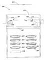
도 1 은 통상적인 프로세싱 툴(113)에 인접하여 기판 캐리어를 저정하기 위한 위치에 있는 통상적인 로딩 및 저장 장치(111)를 도시한 평면도이다. 팩토리 인터페이스(FI)(115)가 로딩 및 저장 장치(111)와 프로세싱 툴(113) 사이에 위치된 것으로 도시되어 있다. 로딩 및 저장 장치(111)는 청정실 벽(117)의 제 1 측면에 인접하여 위치되며, 팩토리 인터페이스(115)는 청정실 벽(117)의 제 2 측면에 인접 하여 위치된다. 팩토리 인터페이스(115)는, 청정실 벽(117)에 평행한 트랙(도시 안 됨)을 따라 수평방향으로 이동하고 로딩 및 저장 장치(111)에 존재하는 하나 이상의 기판 캐리어(120)로부터 기판(도시 안 됨)을 추출하는 FI 로봇(119)을 포함한다. FI 로봇(119)은 기판을 프로세싱 툴(113)의 로드 록 챔버(121)로 전달할 것이다.1 is a plan view illustrating a conventional loading and
도 1 에 도시된 로드 록 챔버(121)는 프로세싱 툴(113)의 전달 챔버(123)에 연결된다. 또한, 전달 챔버(123)에는 처리 챔버(125) 및 보조 처리 챔버(127)가 연결된다. 각각의 처리 챔버(125) 및 보조 처리 챔버(127)는 산화, 박막 증착, 에칭, 열처리, 가스제거, 냉각 등과 같은 통상적인 반도체 장치 제조 공정을 수행할 것이다. 기판 핸들링 로봇(129)은 전달 챔버(123)내에 배치되어 프로세싱 챔버(125, 127) 및 로드 록 챔버(121)들 사이에서 기판(131)과 같은 기판을 전달한다.The
로딩 및 저장 장치(111)는 기판 캐리어내에 수용된 기판이 프로세싱 툴(113)에 의해 처리되기 전후에 기판 캐리어를 저장하기 위한 하나 이상의 기판 캐리어 저장 선반(133)을 포함한다. 로딩 및 저장 장치(111)는 또한 하나 이상의 도킹 스테이션[도시되지 않았지만, 예를 들어, 저장 선반(133) 아래쪽에 있을 수 있다]을 포함한다. 기판 캐리어는 FI 로봇(119)을 이용하여 기판을 추출하기 위해 도킹 스테이션에 도킹될 것이다. 또한, 로딩 및 저장 장치(111)는 공장 로드 위치(135)를 포함하며, 상기 공장 로드 위치에서는 자동 안내 차량(AGV)과 같은 기판 캐리어 전달 장치가 기판 캐리어를 내려 놓거나 실을 것이다.The loading and
로딩 및 저장 장치(111)는 공장 로딩 위치(135), 저장 선반(133) 및 도킹 스테이션 사이에서 기판 캐리어를 이동시키는 기판 캐리어 핸들러(137)를 더 포함한다.The loading and
팩토리 설비내에서 기판의 전달을 용이하게 하는 상기한 바와 같은 목적에 따라, (예를 들어, 잔류 시간 및 그에 따른 재공품을 감소시키고 제조 비용을 감소시키기 위해) 계속적으로 이동하는 기판 캐리어 이송기에 의해 로딩 및 저장 장치(111)와 같은 기판 로딩 스테이션 내외로 기판 캐리어를 전달하는 것이 바람직하다. 결과적으로, 본 발명에 따라, 기판 캐리어 이송기의 이동중에, 기판 캐리어 이송기로부터 기판 캐리어를 언로딩할 수 있고, 기판 캐리어 이송기상으로 기판 캐리어를 로딩할 수 있는 본 발명의 기판 로딩 스테이션이 제공된다.Loading by means of a continuously moving substrate carrier conveyor (e.g., to reduce the residence time and consequent work in progress and to reduce manufacturing costs), in accordance with the purpose as described above to facilitate the transfer of the substrate in the factory facility. And transferring the substrate carrier into and out of a substrate loading station, such as
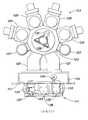
이하에서는 도 2a 내지 도 6e 를 참조하여 본 발명의 실시예를 설명한다. 도 2a 는 본 발명에 따라 제공된 기판 로딩 스테이션(201)의 정면도이다. 도 2a 에는 도시되지 않았지만, 본 발명의 기판 로딩 스테이션(201)은 도 1 과 관련하여 설명한 종류의 프로세싱 툴 및/또는 팩토리 인터페이스와 관련될 수 있다는 것을 이해하여야 한다.Hereinafter, an embodiment of the present invention will be described with reference to FIGS. 2A to 6E. 2A is a front view of a
기판 로딩 스테이션(201)은 처리 장치 내외로 전달하기 위해 기판 또는 기판 캐리어가 위치되는 하나 이상의 로딩 포트 또는 유사 위치를 포함한다(예를 들어, 하나 이상의 도킹 스테이션(203), 그러나 도킹/도킹해제 이동을 채용하지 않는 전달 위치가 도입될 수도 있다). 도 2a 에 도시된 특정 실시예에서, 기판 로딩 스테이션(201)은 각각 4개의 도킹 스테이션으로 이루어진 두개의 종렬(205)로 배치된 총 8개의 도킹 스테이션(203)을 포함한다. 다른 개수의 종렬 및/또는 도킹 스테이션을 채용할 수도 있다. 각각의 도킹 스테이션(203)은 도킹 스테이션(203)에서 기판 캐리어(207)를 지지 및/또는 도킹하며 그리고 도킹 스테이션(203)에서 기판 캐리어(207)로부터 기판(도시 안 됨)이 추출되고 도 1 의 프로세싱 툴(113)와 같은 처리 장치로 전달(예를 들어, 도 1 의 팩토리 인터페이스 로봇(119)과 같은 팩토리 인터페이스 로봇에 의해)될 수 있도록 한다. 본 발명의 일 실시예에서, 기판 캐리어(207)는 단일 기판 캐리어이다. "단일 기판 캐리어"는 한 번에 하나의 기판만을 수용하도록 크기가 정해지고 성형된 기판 캐리어를 의미하는 것으로 이해될 수 있을 것이다. 또한, 하나 이상의 기판을 수용하는 기판 캐리어도 이용될 수 있다(예를 들어, 25개 또는 기타 개수). (대안으로, 하나 이상의 도킹 스테이션(203)은 기판 캐리어 없이 기판에 바로 적용될 수 있다.) 예컨대, "도킹 스테이션에서 도킹 그리퍼를 갖춘 웨이퍼 로딩 스테이션(Wafer Loading Station with Docking Gripers at Docking Stations)"이라는 발명의 명칭을 가지는, 상기 병합된 미국특허출원 제 60/407,337호(2002년 8월 31일)에 기재된 바와 같이, 각각의 도킹 스테이션(203)이 구성될 수 있다. 다른 도킹 스테이션 구성을 사용할 수도 있다.
각각의 도킹 스테이션(203)은 포트(209)를 포함할 수 있는데, 이 포트(209)를 통해 기판이 팩토리 인터페이스[예컨대, 도 1의 팩토리 인터페이스(115)]에 이송된다. 인접하는 각각의 포트(209)는 기판 캐리어(207)를 현수하고 이러한 현수된 기판 캐리어를 도킹 위치와 언도킹 위치 사이에서 이동시키게 된다. 각각의 도킹 스테이션(203)에서 각각의 기판 캐리어(207)를 도킹/언도킹 및/또는 (아래로부 터 또는 다른 상태로) 지지하는데 이동식 스테이지 또는 다른 지지체(도시 안됨)가 대안으로 사용될 수 있다. 각각의 포트(209)는 기판 캐리어 오프너(213)를 포함할 수 있는데, 일 양상에서, "웨이퍼 캐리어 도어를 개방/폐쇄 작동시키기 위해 웨이퍼 캐리어 이동을 사용하는 방법 및 장치(METHOD AND APPARATUS FOR USING WAFER CARRIER MOVEMENT TO ACTUATE WAFER CARRIER DOOR OPENING/CLOSING)"라는 발명의 명칭을 가지는, 상기 병합된 미국특허출원 제 60/407,339호(2002년 8월 31일)에 기재된 바와 같이, 이 기판 캐리어 오프너(213)는 언도킹 위치로부터 도킹 위치로 이동할 때 기판 캐리어(207)를 개방시키도록 기판 캐리어(207)의 도킹 이동을 사용하도록 되어 있다. 예컨대, "웨이퍼 클램핑 기구와 도어 래칭을 갖춘 웨이퍼 캐리어(WAFER CARRIER HAVING DOOR LATCHING AND WAFER CLAMPING MECHANISMS)"라는 발명의 명칭을 가지는, 상기 병합된 미국특허출원 제 60/407,340호(2002년 8월 31일)에 기재된 바와 같이, 각각의 기판 캐리어(207)는 기판 클램핑 피쳐 및/또는 캐리어 도어 래칭을 구비할 수 있다. 다른 기판 캐리어 오프너, 도어 래칭, 및/또는 기판 클램핑 구성이 사용될 수 있다.Each
기판 로딩 스테이션(210)은 또한 본 발명에 따라 작동하는 기판 캐리어 핸들러(215)를 포함한다. 본 발명의 하나 이상의 실시예들에서, 기판 캐리어 핸들러(215)는 한 쌍의 수직 가이드(217, 219) 및 이 수직 가이드 상에서의 수직 이동을 위해 장착된 수평 가이드(221)를 포함한다. 수직 가이드(217, 219)를 따라 수평 가이드(221)를 수직 이동시키기 위해 구동시키는데 벨트 드라이브 또는 리드 스크류 및 연관된 모터 또는 모터들(도시 안됨) 또는 다른 적합한 기구가 제공된 다. 수평 가이드(221)를 따라 수평 이동시키기 위해 수평 가이드(221) 상에 지지체(223)가 장착되어 있다. 수평 가이드(221)를 따라 수평으로 지지체(223)를 이동시키기 위해 벨트 드라이브 또는 리드 스크류 및 연관된 모터 또는 모터들(도시 안됨) 또는 다른 적합한 기구가 제공된다.Substrate loading station 210 also includes a
본 발명의 하나 이상의 실시예에서, 수직 가이드(217, 219)는 Bosch, Inc.로부터 구매가능한 부품 No. 1140-260-10, 1768mm과 같은 일체형 가이드/드라이빙 기구를 각각 포함할 수 있다. 마찬가지로, 수평 가이드(221)는 Bosch, Inc.로부터 구매가능한 부품 No. 1140-260-10, 1468mm과 같은 일체형 가이드/드라이빙 기구를 각각 포함할 수 있다. 다른 가이드/드라이빙 기구 시스템들이 사용될 수도 있다.In one or more embodiments of the present invention,
이러한 지지체(223) 상에는 엔드 이펙터(225)가 장착된다. 예컨대, 이 엔드 이펙터(225)는 기판 캐리어(예컨대, 기판 캐리어(207)중 하나)를 지지하게 되는 수평-배향식 플랫폼(227)의 형태일 수 있다. 하나 이상의 실시예에서, 플랫폼(227)은 동적 핀 또는 다른 동적 포지셔닝 피쳐(229)를 구비할 수 있다. [도 2a에서는 2개만의 동적 피쳐(229)가 도시되어 있지만, 3개 또는 그 이상과 같은 기타 다른 수의 동적 핀 또는 피쳐가 플랫폼(227) 상에 제공될 수 있다.] 동적 피쳐(229)는 기판 캐리어(207)의 바닥에서 오목부 또는 그 외의 다른 형상의 피쳐(도 2a에는 도시 안됨)와 협력할 수 있어서, 플랫폼(227) 상의 정확한 포지셔닝 안으로 기판 캐리어(207)을 안내한다. 본 발명의 하나 이상의 실시예에서, 엔드 이펙터(225)는 예컨대, "수평 배향과 수직 배향 사이에서 웨이퍼 캐리어를 재배향시키기 위한 기구를 갖춘 엔드 이펙터(End Effector Having Mechanism For Reorienting A Wafer Carrier Between Vertical And Horizontal Orientations)"라는 발명의 명칭을 가지는, 상기 병합된 미국특허출원 제 60/407,452호(2002년 8월 31일)에 기재된 바와 같이, 수직으로부터 수평으로 그리고 그 반대로 기판 캐리어의 배향을 변화시킬 수 있는 엔드 이펙터를 포함할 수 있다.The
화살표(231)로 개략적으로 나타낸 연속적인 또는 이와 다른 이동식 이송기는 기판 캐리어 핸들러(215)와 기판 로딩 스테이션(201) 위에 위치된다. 이러한 이동식 이송기(231)는 기판 로딩 스테이션(201)으로 그리고 기판 로딩 스테이션(201)으로부터 기판 캐리어(207)와 같은 기판 캐리어들을 이송하게 된다. 본 발명의 일 실시예에서, 연속적인 이동식 이송기(231)는, 상기 병합된 미국특허출원 제 60/407,087호(2002년 1월 27일)에 기재된 바와 유사한 물질 또는 스테인레스 강의 리본으로서 구현될 수 있다. 본 발명은 유사하게 임의의 다른 유형의 연속적인 또는 그 이외의 이동식 이송기와 함께 사용될 수 있다.The continuous or other mobile conveyor, schematically indicated by
기판 로딩 스테이션(201)은 (1)이송기; (2)이송기(231)의 부품들[예컨대, 도 4a 내지 도 4e, 도 6a 내지 도 6e, 및 도 7c 내지 도 7d를 참조하여 아래에 보다 상세히 기술되는 바와 같이 이송기(231)에 의해 이송되는 기판 캐리어를 지지하는데 사용되는 부품들]; 및/또는 (3) 이송기(231)에 의해 이송되는 기판 캐리어들의 위치 및/또는 이동을 검출하기 위한 하나 이상의 센서(233, 235)를 포함할 수 있다. 예컨대, 센서(233)는 기판 로딩 스테이션(201) 상에 장착될 수 있고, 센서(235)는 엔드 이펙터(225) 상에 장착될 수 있다. 임의의 적합한 센서들(예컨대, 비임 센서들, 반사-본위 센서들(reflection-based sensors) 등을 사용할 때, 다른 센서 위치가 채용될 수 있다.The
도 2b는 센서(233)의 예시적인 실시예를 설명하는데 유용한, 기판 로딩 스테이션(201)의 일부분의 측면도이다. 도 2b를 참조하면, 센서(233)는 이송기(231)의 속도 및/또는 위치; 및/또는 기판 캐리어의 위치(및/또는, 아래에 보다 상세히 기술하는 바와 같이 기판 캐리어(207)가 이송기(231)에 의해 이송되는 속도)를 검출하기 위한 제 1 센서 쌍(233a, 233a')을 포함한다. 센서(233)는 또한 이송기(231)에 의해 기판 캐리어(207)가 이송되는지를 검출하기 위한 제 2 센서 쌍(233b, 233b')을 포함할 수 있다. 예컨대, 제 1 센서 쌍(233a, 233a')은 이송기(231)의 높이(elevation)에서 장착될 수 있고, 제 2 센서 쌍(233b, 233b')은 기판 캐리어들이 도 2b에 도시된 바와 같이 이송기(231)에 의해 이송되는 높이에서 장착될 수 있다(예컨대, 기판 로딩 스테이션(201)의 프레임(F)에 연결된 장착 브래킷(B)에 의해, 또는 다른 적합한 장착 기구에 의해). 각각의 센서 쌍은 예컨대, Banner, Inc.에서 구매가능한 모델 No. Q23SN6RMHSQDP 리시버 및 모델 No. M126E2LDQ 광원을 포함할 수 있다. 다른 센서 배열체/타입을 사용할 수도 있다. 센서(235)의 예시적인 실시예들은 도 2c 내지 도2e 및 도 3을 참조하여 아래에 보다 상세히 기재되어 있다.2B is a side view of a portion of the
센서(233, 235)에 그리고 기판 캐리어 핸들러(215)에는 제어기(237)(도 2a)가 연결될 수 있어서, 아래에 보다 상세히 기술하는 바와 같이, 센서(233, 235)로부터 입력(input)을 수신하고, 기판 캐리어 핸들러(215)의 작동을 제어한다. 2개보다 많거나 또는 적은 수의 센서(233, 235)가 제공될 수도 있으며, 도 2a 및 도 2b에 도시된 위치들 이외의 위치에 센서(233, 235)가 장착될 수도 있다. 제어기(237)는 기판 로딩 스테이션(201)이 제공하는 프로세싱 툴의 작동을 제어하는데 사용되는 것과 동일한 제어기일 수도 있고, 또는 별도의 제어기일 수도 있다.A controller 237 (FIG. 2A) may be connected to the
본 발명의 일 실시예에서, [이송기 속도를 간적접으로 측정하기 위해 센서(233)를 사용하지 않고] 이송기의 속도(및/또는 이송기에 의해 이송되는 기판 캐리어의 속도)는 직접 측정될 수 있다. 예컨대, 도 2a에 도시된 바와 같이, 이송기(231)에는 하나 이상의 엔코더(240a, 240b)(아래에 기재됨)가 연결되는데, 이 엔코더들은 이송기(231)의 속도(및 이송기에 의해 이송되는 임의의 기판 캐리어들의 속도)를 직접 측정하고, 제어기(237)에 속도 정보를 제공한다. 2개 보다 많거나 또는 적은 수의 엔코더들을 사용할 수 있다. 각각의 엔코더는 예컨대, U.S. 디지털 엔코더(예컨대, HDS6 직교 엔코더) 또는 임의의 다른 적합한 엔코더를 포함할 수 있다. 이송기 속도 및/또는 위치를 측정하는데 리니어 엔코더, 리졸버, 또는 다른 포지셔닝 장치를 사용할 수도 있다.In one embodiment of the invention, the speed of the feeder (and / or the speed of the substrate carrier conveyed by the feeder) can be measured directly (without using the
도 3은 이송기(231)로부터 기판 캐리어(207)를 언로딩하도록 본 발명에 따라 기판 로딩 스테이션(201)에 의해 실행될 수 있는 예시적인 프로세스를 도해하는 플로우 챠트이다. 도 4a 내지 도 4e는 도 3의 프로세스의 스테이지를 도해하는 개략적인 측면도이다.3 is a flow chart illustrating an exemplary process that may be executed by the
이송기(231)로부터 기판 캐리어(207)를 언로딩하는 작동을 실행할 때, 기판 캐리어 핸들러(215)의 수평 가이드(221)는 수직 가이드(217, 219)의 상단(217a, 219a) 근처에 위치되며, 지지체(223)는 수평 가이드(221)의 상류측(221a) 근처에 위치된다[도 2a에서, 우측에서 좌측으로의 이동이 실행될 수 있지만, 이송기(231)가 우측에서 좌측으로 이동한다면, 좌측편].When performing the operation of unloading the
도 3의 프로세스는 단계(301)에서 시작하며 단계(303)으로 진행된다. 단계(303)에서, 제어기(237)는 [예컨대 센서(233 또는 235)로부터의] 신호를 수신하여, 이송기(231)에 의해 이송되고 기판 로딩 스테이션(201)에 의해 이송기(231)로부터 언로딩되는 기판 캐리어(207)("타깃 기판 케리어(207)")의 존재를 나타낸다. 예컨대, 도 2b를 참조하면, 센서 쌍(233b, 233b')과 연관된 라이트 비임(L)이 타깃 기판 캐리어(207)에 의해 블로킹될 때, 센서 쌍(233b, 233b')이 타깃 기판 캐리어(207)를 검출할 수 있다. 센서 신호가 수신되면, 제어기(237)는 (부착된 엔드 이펙터(225)와 함께) 지지체(223)가 이송기(231)와 동일한 방향으로(예컨대, 도 2a에서 우측으로) 가속되도록 기판 캐리어 핸들러(215)를 제어하여, 지지체(223)를 타깃 기판 캐리어(207)의 위치 및 속도에 거의 일치(matching)시킨다[도 3에서 단계(305)]. 도 4a는 도 3의 프로세스의 이러한 스테이지를 도시한다.The process of FIG. 3 begins at
본 발명의 하나 이상의 실시예에서, 타깃 기판 캐리어(207)의 위치 및 속도에 거의 일치시키도록 엔드 이펙터(225)를 가속시키기에[단계(305)] 앞서, 제어기(237)는 센서(233)[또는 엔코더(240a, 240b)중 하나 이상]를 사용하여 이송기(231)의 속도를 결정한다. 이송기(231)의 위치를 또한 결정한다. 상술한 바와 같이, 센서(233)는 이송기(231)의 속도(및/또는 이송기(231)에 의해 기판 캐리어(207)가 이송되는 속도)를 검출하기 위한 제 1 센서 쌍(233a, 233a')(도 2b)과, 이송기(231)에 의해 기판 캐리어(207)가 이송되는지를 검출하기 위한 제 2 센서 쌍(233b, 233b')을 포함할 수 있다. 이러한 속도 및/또는 위치 결정은 각각의 타깃 기판 캐리어(207)의 언로딩에 앞서 또는 언로딩 동안 주기적으로, 연속적으로 또는 어떤 다른 기간에 실행될 수 있다.In one or more embodiments of the present invention, prior to accelerating the end effector 225 (step 305) to approximately match the position and velocity of the
이송기(231)의 속도에 근거하여, 제어기(237)는 엔드 이펙터(225)를 위한 이동 프로파일(motion profile)을 결정하고, 이 이동 프로파일에 따라 엔드 이펙터(225)의 이동이 타깃 기판 캐리어(207) 및 엔드 이펙터(225)의 속도 및 위치에 거의 일치되도록 이동할 수 있다. 이송기(231)의 속도가 사전 설정된(predetermined) 속도 범위(예컨대, 사전 설정된 이동 프로파일에 따라 엔드 이펙터(225)가 가속, 이동 및/또는 위치된다면, 엔드 이펙터(225)가 타깃 기판 캐리어(207)와 적절하게 정렬되는 것을 보장하는 범위) 내에 있다면, 이러한 이동 프로파일은 "사전 설정(predetermine)"될 수 있어서, 제어기(237)는 언로딩 작동의 실행을 단지 시작(가속 작동을 시작)할 수 있게 한다. 이송기(231)의 속도가 사전 설정된 속도 범위 내에 있지 않다면, 도 3의 프로세스는 종료한다. [예컨대, 엔드 이펙터(225)가 사전 설정된 이동 프로파일에 따라 가속되는 경우, 엔드 이펙터(225)가 타깃 기판 캐리어(207)와 정렬되는 것을 보장하는 사전 설정된 속도 범위 내에 이송기(231)의 속도가 유지된다고 가정해서] 이송기의 속도가 측정되지 않을 지라도, 이러한 사전 설정된 이동 프로파일이 사용될 수 있다.Based on the speed of the
제어기(237)는 예컨대, 사전 설정된 이동 프로파일의 색인표(look up table), 이동 프로파일을 계산하기 위한 알고리즘 등을 사용하여, 엔드 이펙터(225)에 대한 이동 프로파일을 결정하기 위해 이송기(231)의 속도를 사용할 수 있다. 이동 프로파일을 결정하기 위해, 또는 엔드 이펙터(225)에 대한 사전 설정된 이동 프로파일을 사용할 지를 결정하기 위해 이송기 속도가 아니라 기판 캐리어 속도를 측정하여 사용할 수 있음을 이해할 것이다. 각각의 이동 프로파일은 언로딩 작동 동안 엔드 이펙터(225)에 의해 사용되는 상승율, 하강률, 가속도 및 감속도를 모두 포함할 수 있다.The
상술한 바와 같이, 본 발명의 하나 이상의 실시예에서, 이송기(231)는, 상기 병합된 미국특허출원 제 60/407,087호(2002년 1월 27일)에 기재된 바와 같이, (예컨대, 스테인레스 강 또는 다른 적합한 물질로 이루어진) 리본형 밴드를 포함할 수 있다. 이러한 실시예에서, 이송기(231)에는 이송기(231)를 따라 소정의 간격으로 이격된 슬롯들 또는 다른 구멍들[예컨대, 도 2b의 슬롯(231a)]이 제공되는데, 이송기(231)의 슬롯들이 센서 쌍(233a, 233a')(도 2b)에 의해 이동할 때, 센서 쌍(233a, 233a')의 라이트 비임이 이 슬롯들을 통과한다. (이송기 내의 2개의 연속하는 슬롯을 통해) 센서 쌍(233a, 233a')의 라이트 비임의 2개의 연속하는 전송 사이의 시간을 측정함으로써, 그리고 이들 2개의 연속하는 슬롯 사이의 거리를 알고 있으므로, 이송기(231)의 속도를 결정할 수 있다. 각각의 기판 캐리어(207)(도 2c) 위의 슬롯(231a)의 위치는 또한 이송기(231) 및/또는 기판 캐리어(207)의 위치 정보를 또한 제공한다.As noted above, in one or more embodiments of the present invention, the
본 발명의 하나 이상의 실시예에서, 이송기 속도를 바로 판독하기 위해 엔코더(240a, 240b)(도 2a)를 사용할 수 있다. 예컨대, 엔코더(240a, 240b) 각각은 제어기(237)에 이송기 속도 정보를 제공하고, 제어기(237)는 에러 체크 또는 컨피던스 경로의 일부분으로서 엔코더(240a, 240b)로부터 수신된 정보를 비교한다. 이러한 속도 모니터링은 주기적으로, 연속적으로 또는 다른 시간 간격에서 실행될 수 있다. (예컨대, 하나 이상의 엔코더 또는 다른 포지셔닝 장치에 의해) 이송기 속도를 바로 측정함으로써, 그리고 센서(233)[예컨대, 그리고 슬롯(231a)]에 의한 밴드 위치의 위치를 결정함으로써, 아래에 보다 상세히 기술하는 바와 같이, 이송기(231)가 이동 중에 있는 동안, 엔드 이펙터(225)와 이송기(231) 사이에서의 기판 캐리어의 핸드오프(handoffs)를 정밀하게 실행할 수 있다.In one or more embodiments of the present invention, encoders 240a and 240b (FIG. 2A) may be used to directly read the conveyor speed. For example, each of encoders 240a and 240b provides controller speed information to
도 4a에 도시된 타깃 기판 캐리어(207)는 기판 캐리어(207)의 상부 플랜지(402)와 맞물리는 캐리어 맞물림 부재(401)에 의해 이송기(231)에 의해 이송된다. 기판 캐리어(207)를 지지하기 위한 다른 구성[예컨대, 측면, 바닥 등에 의해 기판 캐리어(207)를 지지하는 하나 이상의 기구들]을 사용할 수 있다. 이러한 캐리어 맞물림 부재(401)를 위한 하나의 구성은 상기 병합된 미국특허출원 제 60/443,153호(2003년 1월 27일)에 개시되어 있다.The
화살표(403)는 이송기(231)의 이동 방향을 나타낸다. 도 4a에서, 기판 캐리어 핸들러(215)의 엔드 이펙터(225)는 타깃 기판 캐리어(207)의 아래의 위치에 있는 것으로 도시되어 있고, 타깃 기판 캐리어(207)의 속도와 거의 일치되는 속도에서 이송기(231)와 동일한 방향으로 [화살표(405)로 표시된 바와 같이] 이동된다. 이로써, 엔드 이펙터(225)는 타깃 기판 캐리어(207)의 속도(예컨대, 속도 및 방향)와 거의 일치된다. 또한, 엔드 이펙터(225)는 타깃 기판 캐리어(207)의 위치와 거의 일치된다. 보다 전체적으로, 엔드 이펙터(225)는 타깃 기판 캐리어(207)의 이동(속도 및/또는 위치)과 일치된다. 여기에 사용된 바와 같이, "거의 일치"이라는 용어는, 기판 캐리어 내부에 포함된 기판에 손상을 주지 않고/또는 잠재적으로 손상된 부품을 발생시키지 않고, 이동하는 이송기 및/또는 캐리어 맞물림 부재 상에 기판 캐리어가 로딩 및/또는 언로딩될 수 있도록 충분히 일치된다는 것을 의미한다.
도 4a에 도시된 실시예에서, 타깃 기판 캐리어(207)는 이송기(231)와 함께 이동된다. 따라서, 엔드 이펙터(225)는 또한 이송기(231)의 속도, 속도, 이동 및/또는 위치와 거의 일치된다. 이송기(231)가 타깃 기판 캐리어(207)에 대해 상이한 비율로, 또는 전혀 다르게 이동하는 실시예들도 있다. 예컨대, 캐리어 맞물림 부재(401)는 이송기(231)를 따라 타깃 기판 캐리어(207)를 자체로 이동시킬 수 있다. 이러한 후자의 실시예에서, 엔드 이펙터(225)는 이송기(231)의 속도, 속도 및/또는 위치와 거의 일치되지 않을 수 있다.In the embodiment shown in FIG. 4A, the
본 발명의 하나 이상의 실시예에서, 엔드 이펙터(225)는 트리거(또는 런치) 센서[예컨대, 도 2b의 센서 쌍(233b, 233b')]와 동일한 위치에 위치하는데, 이 트리거 센서는 이송기(231) 상에서 타깃 기판 캐리어(207)의 존재를 검출한다. 이러한 경우에, 단계(305)에서, 트리거 센서와 엔드 이펙터(225)의 상이한 위치를 보정하기 위해 엔드 이펙터(225)의 가속도를 지연시키는 것이 필요할 수 있다. 이러한 "런치(launch) 오프셋"은 예컨대, 엔드 이펙터(225)와 트리거 센서 사이의 거리, 이송기(231)의 속도 등에 좌우된다. 런치 오프셋은 엔드 이펙터(225)에 대한 이동 프로파일과 별도이거나, 또는 이 이동 프로파일로 이루어질 수도 있다.In one or more embodiments of the present invention, the
도 3을 참조하면, 단계(307)에서, [예컨대, 센서(235)(도 2a)로부터의 신호 또는 신호들에 의해] 엔드 이펙터(225)에 대한 타깃 기판 캐리어(207)의 위치를 검출한다. 예컨대, 센서(235)가 Banner, Inc.로부터 구매가능한 모델 No.QS30 센서 시스템 등과 같은 광원/검출기 쌍을 포함한다면 타깃 기판 캐리어(207)를 향해 센서(235)가 라이트의 비임을 방사할 수 있는데, 이 타깃 기판 캐리어(207)는 [엔드 이펙터(225)가 기판 캐리어(207)에 대해 적절하게 위치될 때에만 센서(235)를 향해 라이트를 반사하는 경사진 노치와 같은 적절한 반사면/표면 토포그래피를 기판 캐리어(207)에 제공함으로써] 엔드 이펙터(225)가 타깃 기판 캐리어(207)에 대해 적절하게 위치된다면 센서(235)에 의해서 단지 검출된다. 도 2c는 엔드 이펙터(225)가 타깃 기판 캐리어(207)에 대해 적절하게 위치될 때 타깃 기판 캐리어(207)의 일부분 내에 형성된 노치(243)로부터 반사된 라이트 비임(241)(도 2d)을 검출하도록 위치된 예시적인 센서(235)를 도시하는, 엔드 이펙터(225)의 일부분의 사시도이다. 도 2d는 도 2c의 일부분의 확대 사시도이다. 도 2c 내지 도 2d에 도시된 바와 같이, 센서(235)는 적합한 브래킷 또는 다른 지지 구조체(247)를 통해 엔드 이펙터(225)에 연결될 수 있다. 다른 구성을 사용할 수도 있다.Referring to FIG. 3, in
본 발명의 하나 이상의 실시예에서, 엔드 이펙터(225)가 타깃 기판 캐리어(207)에 적절하게 위치되지 않는다면, 이때 도 3의 프로세스가 종료된다. 대안으로, 본 발명의 다른 실시예에서, 타깃 기판 캐리어(207)에 대한 엔드 이펙터(225)의 위치의 임의의 필요한 조절이 실행될 수도 있다. 예컨대, 동적 핀(229)(도 4a)이 타깃 기판 캐리어(207)의 정렬 피쳐[예컨대 오목 형상 또는 그외 다른 형상의 피쳐(407)] 아래에 적절하게 위치되는 것을 보장하도록 센서(235)로부터 적절한 정렬 신호가 수신될 때까지, 제어기(237)는 엔드 이펙터(225)를 가속 및/또는 감속시킬 수 있다. 단계(307) 및 단계(309)는 타깃 기판 캐리어(207) 및 엔드 이펙터(225)가 이동 중일 때 실시되며, 그리고 엔드 이펙터(225)가 타깃 기판 캐리어(207) 아래에 위치되는 한편 그와 거의 일치되는 속도를 가지도록 실시된다. 따라서, 엔드 이펙터(225)는 타깃 기판 캐리어(207)가 이동 중에 있는 동안 타깃 기판 캐리어(207) 아래에 인접하여 유지되도록 이동된다. 타깃 기판 캐리어(207)와 엔드 이펙터(225)의 상대위치가 여러번 (또는 계속적으로) 인지되고 조절되며, 엔드 이펙터(225)의 위치 및/또는 속도를 타깃 기판 캐리어(207)의 위치 및/또는 속도와 충분히 일치되어 유지되도록 피드백 제어 루프(도시되지 않음)가 채용되는 것을 이해할 수 있을 것이다. 그러나 본 발명에 의한 또다른 실시예에 있어, 단계(307) 및 단계(309)는 생략될 수 있다.[예를 들어, 만일 이송기(231)의 속도와 엔드 이펙터(225)의 시작 시간/위치를 서로 연결시키는 미리 정해진 이동 프로파일이 적용된 경우이다.] 그러한 실시예의 경우에는 센서(235)는 생략될 수 있다.In one or more embodiments of the present invention, if the
센서(235)의 위치에 또는 이에 부가하여, 엔코더(240a 및/또는 240b)가 언로딩 작동동안 이송기 속도를 모니터하기 위해 채용될 수 있다. 언로딩 작동동안 이송기 속도에 있어 총 편차에 반응하여, 제어기(237)는 언로딩 작동을 중지할 수 있다.[예를 들어, 또다른 이동 프로파일을 채용하여 엔드 이펙터(225)가 이송기(231) 또는 그 부근으로 이동하는 기판 캐리어를 방해하지 않도록 한다.] 대안적으로, 이송기의 속도 변화가 작을 경우에는 적합한 언로딩(또는 로딩) 작동을 확인하기 위하여 제어기(237)가 (예를 들어, 가속도나 감속도를 통하여서) 엔드 이펙터의 위치를 조절할 수 있다. 이에 대하여 엔드 이펙터(237)를 포함하는 폐 루프 시스템, 센서(233), 엔코더(240a 및/또는 240b) 및/또는 제어기(237)는 이송기의 속도 변화에도 불구하고 적합한 언로딩(또는 로딩) 작동을 확인할 수 있다.At or in addition to the position of the
상기 엔드 이펙터(225)가 상기 타깃 기판 캐리어(207)에 대하여 적합하게 위치하였다고 가정하면, 단계(311)가 단계(307) 및/또는 단계(309) 뒤에 따른다. 단계(311)에서, 제어기(237)는 기판 캐리어 핸들러(215)를 조절하고 엔드 이펙터(225)는 상승하고 [예를 들어, 수평 가이드(221)은 엔드 이펙터(225)를 들어 올리기 위하여 수직 가이드(217,219)의 위로 올라간다.] 그동안 엔드 이펙터(225)의 수평 속도(및/또는 순간 위치)는 타깃 기판 캐리어(207)의 속도 (및/또는 순간 위치)와 계속해서 충분히 일치하게 된다. 엔드 이펙터(225)의 상승은 엔드 이펙터에 위치한 동적 핀(229)이 타깃 기판 캐리어(207)의 바닥에 위치한 오목부(407)에 결합되도록 한다. 이 때 엔드 이펙터(225)는 이송기(231)가 기판 캐리어(207)을 나르는 높이로 이동된다. 이러한 방법으로 엔드 이펙터(225)는 타깃 기판 캐리어(207)의 바닥에 닿는다.(도 4b에 보여지는 바와 같다.) 본 발명의 하나 또는 그 이상의 실시예에 있어서, 엔드 이펙터(225)는 바람직하게는 도 8a 내지 도 8d에 관하여 하기에 더 기술된 바와 같이 실제적으로 0의 속도 및/또는 가속도를 가지고 타깃 기판 캐리어(207)에 닿는다. 엔드 이펙터(225)가 계속 상승함에 따라 (그동안 엔드 이펙터(225)는 계속해서 타깃 기판 캐리어(207) 와 수평 속도 및/또는 위치가 실제적으로 일치한다.) 도 4c에 도시된 바와 같이, 타깃 기판 캐리어(207) 그리고 특별하게는 그 상측 플랜지(402)는 이송기(231)의 캐리어 체결 부재(401)와의 결합으로부터 상승된다.Assuming that the
다음으로 도 3의 단계(313)에서, 제어기(237)는 기판 캐리어 핸들러(215)를 조절하여 엔드 이펙터(225)의 수평 운동을 조금씩 감속시키고, 이에 따라 타깃 기판 캐리어(207)가 감속된다. 감속의 정도는 타깃 기판 캐리어(207)가 화살표(403)가 지시하는 방향으로 계속 이동할 수 있는 정도이나 이송기(231)보다는 느린 속도이다. 이는 [타깃 기판 캐리어(207)의 플랜지(402)에 로딩되어 있는] 캐리어 체결 부재(401)가 도 4d에 지시한 것과 같이 플랜지(402)의 앞으로 이동할 수 있도록 한다. (도 4d에 보여지는 것처럼) 플랜지(402)의 아래로부터 캐리어 체결 부재(401)가 이동해 나올 때, 엔드 이펙터(225)는 다시 가속하게 되고, 엔드 이펙터(225)의 수평 속도와 거기에 지지되는 타깃 기판 캐리어(207)는 이송기(231)에 의해 운반되는 다른 기판 캐리어들이 타깃 기판 캐리어(207)와 충돌하지 않도록 이송기(231)[예를 들어, 도 4d에서 기판 캐리어 (409)]의 수평 속도에 대체적으로 일치하게 된다.Next, in
도 3의 단계(315)에서, 엔드 이펙터(225)는 이송기(231)로부터 타깃 기판 캐리어(207)를 낮추기 위하여 [예를 들어, 수직 가이드(217,219)를 따라 수평 가이드(221)가 하강함으로써] 하강한다. 타깃 기판 캐리어(207)의 하강은 도 4e에 도시되어 있다. 엔드 이펙터(225)에 지지되는 타깃 기판 캐리어(207)를 가지는 엔드 이펙터(225)는 이 때 감속하게 되고[도 3의 단계(317)], 결국 멈추게 된다. 상기에서 기술한 바와 같이 본 발명에 따른 적어도 하나 이상의 실시예에서 상기 기술한 엔드 이펙터(225)의 가속, 감속, 상승 및/또는 하강은 엔드 이펙터(225)에 대하여 결정된 이동 프로파일에 의해 결정된다. ( 실험적인 이동 프로파일은 도 8a 내지 도 8d에 대하여 하기에서 설명한다.)In
단계(319)에서, 기판 캐리어 핸들러(215)는 도킹 스테이션들(203) 중의 하나로 엔드 이펙터(225)위에 지지된 타깃 기판 캐리어(207)를 이동시킨다.(도 2a) 대안적으로, 만일 로딩 스테이션(201)이 하나 또는 그 이상의 저장 선반 또는 다른 저장 스테이션들을 포함한다면 (예를 들어, 도 2a에 점선으로 표시된, 기판 캐리어를 저장하도록 하는 저장 선반(239), 기판 캐리어 핸들러(215)는 타깃 기판 캐리어(207)를 상기 저장 스테이션 중의 하나로 이동하게 된다. (다른 및/또는 더 많은 저장 스테이션이 채용될 수 있다.) 이 때 도 3의 과정은 단계(321)에서 종료하게 된다. In
타깃 기판 캐리어(207)가 도킹 스테이션(203)들 중의 하나로 오게 되면, 타깃 기판 캐리어(207)는 각각의 도킹 스테이션(203)의 결합 그립퍼(211)에 기판 캐리어 핸들러(215)에 의해 놓이게 된다. 이 때 타깃 기판 캐리어(207)는 도킹 스테이션(203)에 결합하게 되고, 타깃 기판 캐리어(207)로부터 (예를 들어, 도 1의 FI 로봇(119)과 같은 기판 핸들러에 의해) 타깃 기판을 검출하기 위하여 도킹 스테이션(203)의 기판 캐리어 오프너(213)에 의해 열리게 된다. 검출된 기판은 기판 로딩 스테이션(201)와 결합된 프로세싱 툴[예를 들어, 도 1의 프로세싱 툴(113)]로 이동하게 되고 하나 또는 그 이상의 제조 과정이 처리장치에 의해 상기 기판에 적용되게 된다. 프로세싱 툴에서의 과정이 완결되면, 상기 기판은 도킹 스테이션(203)에 위치한 타깃 기판 캐리어(207)로 되돌려지게 되고 상기 타깃 기판 캐리어(207)는 닫히고 도킹 스테이션(203)으로부터 해제된다. 이 때 기판 캐리어 핸들러(215)는 상기 타깃 기판 캐리어(207)를 상기 도킹 스테이션(203)으로부터 이송기(231) 바로 아래 위치로 이동시킨다.(예를 들어, 기판 캐리어(207)가 저장 위치(239)와 같은 저장 위치에 저장되는 것보다 이송기(231)를 되돌아 온다고 가정하자.) 엔드 이펙터(225)의 위에 지지된 기판 캐리어(207)를 가지고, 수평 가이드(221)는 수직 가이드(217, 219)의 상측 단부(217a, 219a) 근처로 이동하고, 지지체(223)는 수평 가이드(221)의 상측 단부(221a)로 이동하게 된다. 이때 기판 캐리어(207)은 도 5 내지 도 6e를 참조하여 하기 설명한 것과 같이 이송기(231)롤 되돌아 전달된다.When the
이송기(231) 위에 타깃 기판 캐리어(207)를 로딩하기 위한 본 발명에 따른 실시과정을 도 5 내지 도 6e를 참고하여 지금부터 설명한다. 도 5는 본 발명에 따른 기판 캐리어 로딩 과정을 나타낸 플로우 차트이다. 도 6a 내지 도 6e는 도 5의 과정에 따른 다양한 단계를 보여주기 위한 개략적인 측면도이다..An embodiment of the present invention for loading the
도 5의 프로세스는 단계(501)에서 시작하여 단계(503)까지 계속된다. 단계(503)에서 제어기(237)은 [예를 들어, 센서(233 또는 235)로부터] 이송기(231)의 빈 캐리어 체결 부재(401)의 존재를 인지하는 신호를 받는다. 이 신호에 반응하여, 단계(505)에서는 제어기(237)은 기판 캐리어 핸들러(215)를 조절하여,[이송기(231)로 전달되는 타깃 기판 캐리어(207) 를 가지는] 엔드 이펙터(225)가 빈 캐리어 체결 부재(401)[및/또는 이송기(231)]의 움직임과 적절하게 일치하도록 수평 가이드(221)을 따라 가속된다. 예를 들어, 엔드 이펙터(225)는 수평방향으로 빈 캐리어 체결 부재(401)의 속도와 위치와 적절하게 일치하게 된다. 상기에서 서술한 것과 같이, 하나 또는 그 이상의 실시예에서 엔드 이펙터(225)는 트리거 센서[예를 들어, 도 2b의 센서 쌍 (233b, 233b′)]와 동일한 위치에 위치해서는 안된다. 그러한 상황에서는, 단계(505)에서 엔드 이펙터(225)와 트리거 센서의 위치차를 보정하기 위하여 엔드 이펙터(225)의 가속도를 지연할 필요가 생긴다.The process of FIG. 5 begins at
본 발명의 적어도 하나의 실시예에서, 엔드 이펙터(225)의 가속전에 엔드 이펙터(225)를 빈 캐리어 체결 부재(401)의 속도와 위치에 적절하게 일치시키기 위하여[단계(505)], 제어기(237)은 이송기(231)의 속도를 결정하기 위하여 이송기(231)에 커플된 하나 또는 그 이상의 엔코더(240a,240b) 또는 센서 (231)를 채용한다. 또한 이송기(231)의 위치를 결정한다. 이송기(231)의 속도에 근거하여, 제어기(237)은 엔드 이펙터(225)의 이동 프로파일과, 타깃 기판 캐리어(207) 가 올려지는 빈 캐리어 체결 부재(401)와 [기판 캐리어(207)을 그 위에 가지고 있는] 엔드 이펙터(225)의 속도 및 위치를 적절하게 일치시키기 위한, 상기 이동 프로파일에 따른 엔드 이펙터(225)의 직접 이동을 결정한다. 이동 프로파일은 미리 결정되어서 제어기(237)은 만일 이송기(231)의 속도가 미리 정해진 속도 범위[예를 들어, 만일 엔드 이펙터(225)가 미리 정해진 이동 프로파일에 따라 가속된 경우, 엔드 이펙터(225)가 빈 캐리어 체결 부재(401)와 적합하게 정렬되는 것이 확실한 범위] 안에 들어온 경우에만, 엔드 이펙터(225)가 로딩 작동의 수행(예를 들어, 가속)을 시작하도록 한다; 그렇지 않다면 도 5의 프로세스가 종료한다.In at least one embodiment of the invention, in order to properly match the
이와 달리, 제어기(237)은, 예를 들어, 미리 결정된 이동 프로파일의 조사표를 사용하거나 또는 이동 프로파일을 계산하기 위한 알고리즘을 사용하는 등 엔드 이펙터(225)의 이동 프로파일을 결정하기 위하여 이송기(231)의 속도를 채용할 수 있다. 엔드 이펙터(225)의 미리 결정된 프로파일의 채용여부를 결정하거나 이동 프로파일을 결정하기 위하여 이송기 속도보다 오히려 캐리어 체결 부재 속도를 측정하고 적용하는 것이 좋다. 각각의 이동 프로파일은 로딩작동 동안 엔드 이펙터(225)에 적용되는 가속도, 감속도, 승강, 그리고 (하기에 기술된) 하강을 모두 포함한다.(예시적인 이동 프로파일은 도 8a-8d와 관련하여 하기에 기술되어 있다.)Alternatively, the
도 6a는 이송기(231)와 적절하게 일치되는 속도로 움직이며, 타깃 기판 캐리어(207)가 로딩된 캐리어 체결 부재(401)보다 아래에서 조금 뒤에 위치한 타깃 기판 캐리어(207)의 플랜지(402)와 적절하게 일치되는 속도로 움직이는 엔드 이펙터(225)를 나타낸 것이다. 이러한 방법으로 타깃 기판 캐리어(207) 는 하기에 기술한 것과 같이 이송기(231)로 타깃 기판 캐리어(207) 를 전달하는 동안 캐리어 체결 부재(401)에 의해 방해되어지는 플랜지(402) 없이 상승할 수 있다. 일반적으로, 타깃 기판 캐리어(207)의 플랜지(402)는 타깃 기판 캐리어(207)가 로딩되는 캐리어 체결 부재(401)에 따라오는 캐리어 체결 부재(및/또는 그위에 위치한 기판 캐리어) 및 타깃 기판 캐리어(207)가 로딩되는 캐리어 체결 부재(401)에 연결되지 않고 타깃 기판 캐리어(207) 가 승강되도록 하는 장소에 위치한다.FIG. 6A shows the
단계(505) 뒤에는[예를 들어, 도 2a의 센서(235)에 의해] 타깃 기판 캐리어(207)와 캐리어 체결 부재(401)의 상대적 수평위치를 감지하는 단계(507)가 뒤따른다. 예를 들어, 만일 센서(235)가 광 소스/ 감지기로 구성된다면, (도 2c 내지 도 2d에서 이와 관련하여 이미 기술한 과 같이) 센서 235는 빈 캐리어 체결 부재(401)로 광선을 쏘아 만일 엔드 이펙터(225)가 빈 캐리어 체결 부재(401)에 대하여 상대적으로 적합하게 위치하고 있는 경우에만 센서(235)에 의해 검지되도록 한다.Step 505 is followed by
도 2e는 이송기(231)에 캐리어 체결 부재(401)를 연결하는 캐리어 체결 부재(401)의 일부분(49)을 감지하기 위하여 위치한 센서(235)를 도시한 엔드 이펙터(225)의 일부분를 나타낸 사시도이다. 특별하게는, 캐리어 체결 부재(401)의 일부분(249)은 로딩작동시 캐리어 체결 부재(401)아래에 엔드 이펙터(225)가 적합하게 위치한 경우 상기 센서(235)쪽으로 광선을 되돌려 보내기 위해 구부러진 노치(251)를 포함한다. 다른 구성도 채용될 수 있다. 예를 들어, 하나 또는 그 이상의 엔코더(240a,240b) 또는 직접 이송기의 속도를 측정하는 위치 측정장치가 (예를 들어,계속적으로) 제어기(237)에 그러한 정보를 제공함으로써 제어기(237)은 로딩작동 동안 이송기의 위치를 추적하게 된다. FIG. 2E is a perspective view of a portion of
본 발명에 의한 실시예중 적어도 하나에 있어서, 만일 엔드 이펙터(225)가 빈 캐리어 체결 부재(401)에 대하여 적합하게 위치하지 않는다면, 이 때 도 5의 프로세스는 종료한다. 대안적으로, 본 발명에 의한 다른 실시예에 있어서, [예를 들어, 타깃 기판 캐리어(207) 가 하기에 설명한 것과 같이 상승할 때 플랜지(402)가 캐리어 체결 부재(401)에 닿지 않는 것을 확인하기 위하여] 단계(509)에서 타깃 기판 캐리어(207) 와 캐리어 체결 부재(401)의 상대적 수평 위치를 조정할 필요가 있다. 예를 들어, 제어기(237)는 센서(235)로부터 적절한 정렬 신호가 받아들여질 때까지 엔드 이펙터(225)를 가속 및/또는 감속한다. 그러한 위치조정 동안, 타깃 기판 캐리어(207)의 수평 속도와 이송기(231) 및/또는 캐리어 체결 부재(401)의 수평 속도는 적당하게 일치되게 유지된다. 그러나 본 발명의 또 다른 실시예에서, [예를 들어, 만일 이송기(231)의 속도 및/또는 엔드 이펙터(225)의 착수 시간/위치 와 관련된 미리 정해진 이동 프로파일이 있다면] 단계(507 및 509)는 생략가능하다. 그러한 실시예에 있어서, 센서(235)는 생략가능하다.In at least one of the embodiments according to the present invention, if the
만일 엔드 이펙터(225)가 빈 캐리어 체결 부재(401)에 대하여 적합하게 위치하고 있다고 가정한다면, 단계(511)에서, 도 6b에서 보이는 것처럼, 수직 가이드(217,219)(도 2a)를 따라 수평 가이드(221)가 상승함으로써, 엔드 이펙터(225)는 상승하고, 타깃 기판 캐리어(207)와 특별하게는 그 플랜지(402)가 캐리어 체결 부재(401)의 수준까지 오게 된다. 도 6b에 보이는 바와 같이, (예를 들어, 하기에 설명하는 것과 같이 그 위에 로딩하는 동안) 플랜지(402)는 캐리어 체결 부재(401)의 약간 위에 위치한다.If it is assumed that the
다음으로, 도 6c에서 보여지고 단계(513)에서 나타나는 것처럼, 타깃 기판 캐리어(207)는 이송기(231)의 캐리어 체결 부재(401) 위에 타깃 기판 캐리어(207)의 플랜지(402)를 가져오기 위하여 가속된다. 이 때 타깃 기판 캐리어(207)는 감속되고, 타깃 기판 캐리어(207)의 수평 속도는 다시 이송기(231)의 수평 속도와 적절하게 일치된다. 다음으로 도 6d에 도시되고 단계(515)에서 나타난 것처럼, 타깃 기판 캐리어(207)의 플랜지(402)를 이송기(231)의 캐리어 체결 부재(401)와 체결되도록 가져오기 위하여, [계속해서 이송기(231)의 수평 속도와 적절하게 일치하는 동안에] 엔드 이펙터(225)는 하강하고, 이에 의하여 타깃 기판 캐리어(207)를 캐리어 체결 부재(401)에 놓게 된다. 본 발명의 하나 또는 그 이상의 실시예에서, 타깃 기판 캐리어(207)는 도 8a 내지 도 8b를 참조하여 하기에 더 기술하는 것처럼 대체적으로 0의 속도 및/또는 가속도를 가지고 캐리어 체결 부재(401)에 접하는 것이 바람직하다. 제어기(237)에 의해 조절되는 기판 캐리어 핸들러(215)는 계속해서 엔드 이펙터(225)를 하강시키고, [예를 들어, 이송기(231)의 수평 속도와 계속해서 적절하게 일치하도록 하는 동안] 엔드 이펙터(225)의 동적 핀(kinematic pin; 229)은 타깃 기판 캐리어(207)의 바닥의 부분(407)으로부터 떨어지게 된다. 단계(517)의 예시적인 결과는 도 6e에 도시되어 있다.Next, as shown in FIG. 6C and shown in
엔드 이펙터(225)가 타깃 기판 캐리어(207)로부터 떨어진 후에, 단계(519)에서 엔드 이펙터(225)는 감속한다.(예를 들어, 정지한다.) 그리고 도 5의 과정은 종료한다.[단계(521)] 그러는 동안 이송기(231)의 캐리어 체결 부재(401)에 의해 그 플랜지(402)를 통하여 지지되던 타깃 기판 캐리어(207)는 로딩 스테이션(201)으로부터 이송기(231)에 의하여 전달된다. 상기에서 기술한 바와 같이, 본 발명의 적어도 하나의 실시예에서, 상기 기술된 엔드 이펙터(225)의 가속, 감속, 승강 및/또는 하강은 엔드 이펙터(225)를 위해 결정된 이동 프로파일에 의해 정해진다.After the
따라서, 본 발명에 따른 기판 로딩 스테이션(201), 그리고 특별하게는 제어기(237)의 조절에 의해 작동하는 기판 캐리어 핸들러(215)는 움직이는 이송기로부터 기판 캐리어를 언로딩하고, 움직이는 이송기로 기판 캐리어를 로딩하기 위한 기 능을 한다. 이러한 방법으로 본 발명의 기판 로딩 스테이션과 기판 캐리어 핸들러는 조립설비, 진행중 작업, 그리고 작업 자본 및 제조 비용에서의 기판 정지 시간을 줄일 수 있다.Thus, the
본 발명에 따라, 제어기(237)는 도 3 및 도 5의 프로세스 중 하나 또는 모두를 수행하도록 프로그램될 수 있다. 또한 도 3 및 도 5의 프로세스는 하나 또는 그 이상의 컴퓨터 프로그램에 의해서 구체화될 수 있다. 각각의 컴퓨터 프로그램은 컴퓨터에 의해 읽어질 수 있는 매체(예를 들어, 캐리어 파동 신호, 플로피 디스크, 하드 드라이브, 랜덤 액세스 메모리 등)에 의해 수행된다.In accordance with the present invention,
본 발명의 적어도 하나의 실시예에 있어서, 본 발명의 기판 로딩 스테이션(201)은 전원이 꺼지거나, 긴급한 중단 등의 상황이 발생하면, 이송기(231)로부터 엔드 이펙터(225)를 자동적으로 회수하도록 형성된다. 예를 들어, 제어기(237)은 전원이 꺼지거나 긴급한 중단 등의 상황과 같은 미리 정해진 방해에 대응하여 이송기(231)로부터 엔드 이펙터(225)[및/또는 수평 가이드(221)]를 자동적으로 회수하도록하는 엔드 이펙터 회수 루틴을 포함하고 있다. 더 나아가, 엔드 이펙터(225)[및/또는 수평 가이드(221)]는 편향되어, 엔드 이펙터(225)[및/또는 수평 가이드(221)]는 전원이 기판 로딩 스테이션(201)으로부터 로딩되면 자동적으로 회수된다. 스프링, 중력, 에어 실린더, 볼 스크류, 리드 스크류 등과 같은 적합한 편향 기구가 채용될 수 있다. 상기에서 언급한 엔드 이펙터 회수 루틴은 예를 들어 하나 또는 그 이상의 컴퓨터 프로그램 결과로서 수행될 수 있다.In at least one embodiment of the present invention, the
기판 로딩 스테이션(201)의 설계에 영향을 미치는 전형적인 파라미터는, 예 를 들어, (1)이송기 속도; (2)기판 캐리어 핸들러(215)가 엔드 이펙터(225)를 움직일 수 있는 수평 및/또는 수직 속도; (3)기판 캐리어 핸들러(215)의 엔드 이펙터(225)에 적용될 수 있는 수평 및/또는 수직 가속도 및 감속도; (4)기판 캐리어 핸들러(215)의 엔드 이펙터(225)의 수평 및 수직 이동 거리; (5)이송기(231)에 의해서 이동될 수 있는 근접한 기판 캐리어(207) 사이의 거리; (6)이송기(231)가 기판 캐리어(207)을 운반할 수 있는 높이; (7)기판 캐리어(207)를 운반하는 이송기(231)의 캐리어 체결 부재(401)를 언로딩하기 위해 기판 캐리어(207)이 들어올려져야 하는 수직 거리; (8)기판 캐리어(207) 각각의 높이(예를 들어, 수직 높이) (9)기판 캐리어가 해제된 기판 캐리어(207)에 부딪히지 않고 해제된 기판 캐리어 의 위로 지나기 위하여 이송기(231)에 의해 전달되도록 하는, 캐리어 체결 부재(401)로부터 해제된 후, 기판 캐리어(207)가 하강해야 하는 거리; (10)적용되는 캐리어 체결 부재의 종류; 및/ 또는 (11)다른 유사한 파라미터들이다.Typical parameters affecting the design of the
예를 들어, 본 발명에 따른 적어도 하나의 실시예에서, 본 발명의 기판 캐리어 핸들러(215)는 (1)이송기(231)의 수평 속도보다 크거나 또는 같은 엔드 이펙터(225)의 최대 수평 속도를 가져야 하며 (2)이송기 캐리어 체결 부재(401)로부터 기판 캐리어를 언로딩하고 떨어지도록 엔드 이펙터(225)를 충분한 높이만큼 들어올릴 수 있어야 하며; (3)도킹 스테이션(203)으로 그리고 도킹 스테이션(203)으로부터 기판 캐리어(207)를 운반하기 위한 제 2 수평 속도 및 이송기 속도와 일치하기 위한 제 1 수평 속도와 같이 둘 또는 그 이상의 수평 속도로 이동할 수 있어야 하며; (4)도킹 스테이션(203)으로 그리고 도킹 스테이션(203)으로부터 기판 캐리어(207)를 운반하기 위한 제 2 수직 속도 및 이송기(231)에 기판 캐리어(207)를 놓아두거나 이송기(231)로부터 기판 캐리어(207)를 떼어내기 위한 제 1 수직 속도와 같은 둘 또는 그 이상의 수직 속도로 움직일 수 있어야 하며; (5)기판 캐리어(207) 안에 담겨진 하나 또는 그 이상의 기판들의 손상없이 엔드 이펙터(225)에 의해 지지되는 기판 캐리어(207)의 [그리고 이송기(231)로부터 떨어지거나 로딩되기 위하여 기판 캐리어에 요구되는] 가속과 감속이 잘 수행될 수 있어야 한다.For example, in at least one embodiment according to the present invention, the
또한, 기판 캐리어 핸들러(215)는 가장 낮은 도킹 스테이션(203)까지 작용할 수 있도록 엔드 이펙터(225)를 충분히 낮은 위치까지 낮출 수 있도록 작동되어야 한다.[만일 가장 낮은 도킹 스테이션(203)보다 더 낮은 곳에 저장 선반이나 저장 스테이션이 위치한다면, 기판 캐리어 핸들러(215)는 반드시 가장 낮은 저장 선반/스테이션에 작용할 수 있도록 엔드 이펙터(225)를 낮게 더 이동시킬 수 있어야 한다.] 수평 가이드(221)에 제공되는 엔드 이펙터(225)의 수평 이동 범위, 그리고 엔드 이펙터(225)의 이동을 위한 기구는, 반드시 엔드 이펙터(225)가 이송기 속도와 적절하게 일치될 수 있는 수평 속도로 가속될 수 있고, [이송기(231)로 전달되는 다른 기판 캐리어들과의 충돌을 피하면서] 이송기(231)에 기판 캐리어(207)를 로딩하고 및/또는 이송기(231)로부터 기판 캐리어(207)을 언로딩할 수 있어야 한다. 그리고 수평 가이드(221)에 의해 제공되는 가능한 모든 수평이동범위 내에서 정지하기 위하여 감속할 수 있어야 한다.In addition, the
본 발명인 기판 로딩 스테이션의 하나 또는 그 이상의 실시예에서는 상기 기 술된 형상/파라미터들의 모두 또는 일부가 포함된다.In one or more embodiments of the substrate loading station of the present invention, all or some of the above-described shapes / parameters are included.
도 7a 내지 도 7d를 참조하여 지금부터 살펴볼 제어기(237)(도 2a)의 프로그래밍과 및/또는 본 발명의 기판 로딩 스테이션(201)의 특별한 장치를 설계하기 위하여 다양한 요소들과 파라미터들이 고려되어야 한다. 도 7a와 7b는 본 발명의 기판 로딩 스테이션(201)의 단순화된 정면도이고, 도 2a와 유사하다. 도 7c 내지 도 7d는 도 4a 내지 도 4e 및 도 6a 내지 도 6e와 유사한데, 이송기(231)로부터 언로딩되고 및/또는 이송기(231)에 로딩되는 동안의 기판 캐리어의 단순화된 작동 측면도이다. Various elements and parameters must be considered to program the controller 237 (FIG. 2A) and / or to design a particular apparatus of the
기판 캐리어 핸들러(215)의 엔드 이펙터(225)의 수평 범위는 도 7a에 도시되어 있다. 엔드 이펙터(225)와 지지체(223)는 기판 캐리어 핸들러(215)의 수평 가이드(221)를 따라 이동하는데, 엔드 이펙터(225)의 상측 이동 제한 범위의 위치가 실선으로 보여진다. 엔드 이펙터(225)와 지지체(223)는 기판 캐리어 핸들러(215)의 수평 가이드(221)를 따라 이동하는데, 엔드 이펙터(225)의 하측 이동 제한 범위의 위치가 가상선으로 보여진다. 도 7a에 도시된 거리 DHR은 엔드 이펙터(225)의 최대 수평 이동 범위를 나타낸다.The horizontal range of the
수평이동 범위DHR의 선택은, 상기에서 기술된 설계 요소의 영향을 받는데, 도킹 스테이션(203)과 선반(239)의 위치[예를 들어, 도킹 스테이션 또는 선반의 수평 길이 및/또는 수량] 기판 로딩 스테이션(201)의 바람직한 밑넓이, 기판 로딩 스테이션(201)과 결합하는 작업도구 또는 공장의 인터페이스의 크기 등에 의한 영향 을 또한 받는다.The choice of the lateral movement range DHR is influenced by the design elements described above, where the position of the
엔드 이펙터(225)의 수직 이동 범위가 도 7b에 도시되어 있다. 엔드 이펙터(225), 지지체(223) 그리고 수평 가이드(221)가 엔드 이펙터(225)의 수직이동범위의 상측제한선인 "703"에 실선으로 보여진다. 그 위치에서, 엔드 이펙터(225)는 EH의 높이를 가지고, 그 높이는 이송기(231)의 캐리어 체결 부재(401)로부터 기판 캐리어(207)의 플랜지(402)를 언로딩할 정도로 충분한 높이이다.(도 4b 내지 도 4d 참조)The vertical movement range of the
도 7b를 계속 언급하면, 엔드 이펙터(225), 지지체(223) 그리고 수평 가이드(221)가 엔드 이펙터(225)의 수직이동 범위의 하한 제한선인 "704"에 가상으로 보여진다. 그 위치에서, 엔드 이펙터(225)는 EL의 높이이고, 기판 로딩 스테이션(201)의 최저 도킹 스테이션(또는 저장 대)에 적용하기 위하여 요구되는 최저 높이이다. 도 7b에 도시된 거리(DVR)는 엔드 이펙터(225)의 최대 수직 이동 범위이다. (예를 들어, DVR= EH-EL) 다른 수직 이동 범위가 적용될 수 있다.With continued reference to FIG. 7B, the
이송기(231)로부터 기판 캐리어(207)를 로딩하고 언로딩하기 위한 작동에 영향을 미치는 파라미터들은 도 7c 내지 도 7d에 도시되어 있다. 도 7c는 이송기(231)에 의해 전달되는 두개의 근접한 기판 캐리어들(207)이 분리된 거리(DS)를 보여준다. 분리거리(DS)는 캐리어 체결 부재(401)사이의 거리(DCEM)와 관련되나 이보다는 작고, 또한 기판 캐리어(207)의 수평 치수와 관련되어 있다. 거리(DS)를 증가시키는 것은 로딩 및 언로딩 작업동안 기판 캐리어(207)을 승강, 하강, 가속 및/또는 감속을 위하여 더 큰 공간 및/또는 시간 간격를 제공함으로써 로딩 및 언로딩 작업을 쉽게 한다. 그러나, 거리(DS)를 증가시키는 것은 대개, 이송기(231)에 의해 이송될 수 있는 기판 캐리어의 수를 감소시킨다.Parameters affecting the operation for loading and unloading the
도 7d에 도시된 바와 같이, 본 발명의 하나 이상의 실시예에서, 이송기(231)로부터 기판 캐리어(207)를 연결해제하기 위해, 엔드 이펙터(225)는 기판 캐리어(207)의 적어도 바닥의 고도(ECB)와 동일한 고도까지 동적 피쳐(229)를 상승시킨다. 보다 구체적으로, 기판 캐리어(207)를 지지하는 캐리어 맞물림 부재(401)의 시트의 높이(HCEM)에 고도(ECB)를 가산한 것과 동일 또는 그 이상의 고도까지(예컨대, 캐리어 맞물림 부재(401)로부터 기판 캐리어(207)의 플랜지(402)를 제거하기 위해) 동적 피쳐(229)가 상승된다. 연결해제된 기판 캐리어(207)를 하강시키기 전에, 플랜지(402)의 길이(LF) 이상의 총 거리만큼 캐리어 맞물림 부재(401)가 기판 캐리어(207)의 전방으로 이동할 수 있도록 엔드 이펙터(225) 감속된다. 본 발명의 기판 로딩 스테이션(201) 및 기판 캐리어 핸들러(215)의 구성에 다수의 다른 파라미터가 영향을 줄 수 있다.As shown in FIG. 7D, in one or more embodiments of the present invention, in order to disconnect the
전술한 설명은 본 발명의 예시적인 실시예만을 개시한 것이며, 본 발명의 범위 내에 해당하는 방법들 및 상기 개시된 장치의 변경예는 당업자에게 명확할 것이다. 예컨대, 상술한 기판 캐리어 핸들러(215) 내에 2개의 수직 가이드를 사용하는 대신, 하나만의 수직 가이드를 사용할 수도 있다. 또한, 수직 가이드를 따라 수직 이동을 위해 연결된 수평 가이드 대신에, 기판 캐리어 핸들러는 수평 가이드를 따라 수평 이동을 위해 연결된 수직 가이드에 의해 정렬될 수 있다.The foregoing description discloses only exemplary embodiments of the invention, and methods and variations of the disclosed apparatus that fall within the scope of the invention will be apparent to those skilled in the art. For example, instead of using two vertical guides in the
기판 캐리어 핸들러가 수평 가이드를 따라 이동을 위해 장착된 수직 가이드를 포함하는 경우, 이송기로부터 기판 캐리어를 연결해제하기 위한 엔드 이펙터의 상승, 또는 이송기에 기판 캐리어를 핸드오프하기 위한 엔드 이펙터의 하강은, (예컨대, 한 쌍의 수직 가이드에 대해 수평 가이드를 상승시키는 것에 의해서가 아니라) 수직 가이드를 따라 엔드 이펙터를 상승 또는 하강시킴으로써 실행될 수 있다. [수직 가이드 또는 가이드들을 따라 수평 가이드(221)를 상승/하강시키는 것에 추가로 또는 그 대신에] 이송기(231)로부터 기판 캐리어를 연결해제시키도록 수평 가이드(221)에 대해 엔드 이펙터(225)를 상승시키기 위해, 또는 이송기(231)에 기판 캐리어를 핸드 오프시키도록 수평 가이드(221)를 향해 엔드 이펙터(225)를 하강시키기 위해, 기판 캐리어 핸들러(215)의 지지체(223) 상에 (도시되지 않은 벨트 드라이브 또는 리드 스크류와 같은) 액츄에이터가 제공될 수 있다.If the substrate carrier handler includes a vertical guide mounted for movement along the horizontal guide, the rise of the end effector for disconnecting the substrate carrier from the conveyor, or the drop of the end effector for handing off the substrate carrier to the conveyor, , By raising or lowering the end effector along the vertical guide (eg, not by raising the horizontal guide relative to a pair of vertical guides).
본 발명은 수직 배향으로 기판 캐리어를 이송하는 이송기 상에 기판 캐리어를 로딩하고, 이 이송기로부터 기판 캐리어를 언로딩하는데 사용될 수 있다. 이러한 경우에, 엔드 이펙터(225)는 수직 배향과 수평 배향 사이에 기판 캐리어를 재배향시키기 위한 재배향 기구를 포함할 수 있는데, 이는 "수직 및 수평 배향 사이에서 웨이퍼 캐리어를 재배향시키기 위한 기구를 갖춘 엔드 이펙터(End Effector Having Mechanism for Reorienting a Wafer Carrier Between Vertical and Horizontal Orientations)"라는 발명의 명칭의, 상기 병합된 미국특허출원 제 60/407,452호(2002년 8월 31)에 개시되어 있다.The present invention can be used to load a substrate carrier on a conveyor that carries the substrate carrier in a vertical orientation, and to unload the substrate carrier from this conveyor. In such a case, the
본 발명은 하나의 기판 캐리어에 관해 도시되어 있지만, 본 발명은 하나 이상의 기판을 유지시키는 기판 캐리어와 함께 사용될 수 있다.Although the present invention is illustrated with respect to one substrate carrier, the present invention may be used with a substrate carrier holding one or more substrates.
여기에 도해된 기판 로딩 스테이션의 특정 실시예는 복수의 수직 스택으로 배열된 도킹 스테이션을 포함한다. 그러나, 상술한 기판 로딩 스테이션은 하나만의 수직 스택의 도킹 스테이션, 하나만의 도킹 스테이션 또는 2개 이상의 수직 스택의 도킹 스테이션을 포함할 수도 있다. 기판 로딩 스테이션은 하나 이상의 저장 선반, 및/또는 저장 선반이 아닌 하나 이상의 기판 캐리어 저장 설비를 포함할 수 있다.Particular embodiments of the substrate loading station illustrated here include docking stations arranged in a plurality of vertical stacks. However, the substrate loading station described above may include only one vertical stack of docking station, only one docking station, or two or more vertical stacks of docking station. The substrate loading station may include one or more storage shelves and / or one or more substrate carrier storage facilities that are not storage shelves.
여기에 도해된 예시적인 기판 로딩 스테이션에서, 도킹 스테이션은 도킹 위치와 언도킹 위치 사이에 기판 캐리어를 이동시키도록 기판 캐리어를 현수하는 도킹 그리퍼를 포함하도록 도시되어 있다. 대안으로, 도킹 스테이션은 도킹 슬레드 또는 플랫폼을 포함할 수 있는데, 이는, 도킹 위치와 언도킹 위치 사이에서 기판 캐리어를 이동시키는 동안, 기판 캐리어의 바닥 또는 측면들 등에 의해 아래로부터 기판 캐리어를 지지한다.In the example substrate loading station illustrated herein, the docking station is shown to include a docking gripper that suspends the substrate carrier to move the substrate carrier between the docked position and the undocked position. Alternatively, the docking station may include a docking sled or platform, which supports the substrate carrier from below by the bottom or sides of the substrate carrier, etc. while moving the substrate carrier between the docked position and the undocked position. .
바람직하게, 본 발명은 수직 및 수평 가이드들이 연결되는 프레임을 포함하는 기판 로딩 스테이션 내에 사용된다. 이러한 방법으로, 바람직한 기판 로딩 스테이션은 모듈이며, 설치되고 교정될 수 있다. 이 경우에, 기판 로딩 스테이션은 하나 이상의 저장 선반(예컨대, 도 2a의 저장 선반)을 포함하며, 각각의 저장 선반은 또한 프레임 상에 장착될 수 있다. 기판 캐리어 핸들러 및 저장 선반 또는 선반들 모두를 프레임에 장착함으로써, 기판 캐리어 핸들러 및 저장 선반은 서로에 대해 사전 설정된 위치를 가진다. 이것은 설치 및 교정을 보다 용이하게 하고, 모듈의 기판 로딩 스테이션을 사용하는 다른 장점이 된다. 유사하게, 오버헤드 팩토리 이송 시스템으로부터 기판 캐리어를 로딩 및/또는 언로딩하기 위한 봉헌된 기구는, 여기에 개시된 바와 같이, 그리고, "웨이퍼 캐리어를 이송하기 위한 시스템(System For Transporting Wafer Carriers)"라는 발명의 명칭의, 상기 병합된 미국특허출원 제 60/407,451호(2002년 8월 31일)에 개시된 바와 같이, 프레임 상에 유리하게 장착된다.Preferably the invention is used in a substrate loading station comprising a frame to which vertical and horizontal guides are connected. In this way, the preferred substrate loading station is a module, which can be installed and calibrated. In this case, the substrate loading station includes one or more storage shelves (eg, storage shelves of FIG. 2A), each storage shelf may also be mounted on a frame. By mounting both the substrate carrier handler and the storage shelf or shelves to the frame, the substrate carrier handler and the storage shelf have a preset position relative to each other. This makes installation and calibration easier and another advantage of using the substrate loading station of the module. Similarly, a dedicated mechanism for loading and / or unloading a substrate carrier from an overhead factory transport system is, as disclosed herein, and referred to as "System For Transporting Wafer Carriers." It is advantageously mounted on a frame, as disclosed in the incorporated US patent application Ser. No. 60 / 407,451 (August 31, 2002), of the title of the invention.
일 양상에서, 프레임은 클리닝 룸의 벽 위 또는 챔버(예컨대, 팩토리 인터페이스 챔버)의 전방벽 상에서 사전 설정된 장착 위치(사전 드릴링된 볼트 구멍 등)에 장착될 수 있다. 바람직하게, 벽은 또한 사전 설정된 장착 위치를 가지는데, 이 장착 위치에는 도킹 크리퍼 또는 도킹 플랫폼이 장착된다. 또한, 벽은, 기판 캐리어 오프닝 기구가 장착될 수 있는 사전 설정된 장착 위치를 구비할 수 있다. 프레임, 도킹 기구, 및 기판 캐리어 오프닝 기구가 동일한 표면 상의 사전 설정된 위치에 각각 장착될 때, 이들 각각의 상대 위치는 사전 설정되어 있고, 기판 로딩 스테이션의 설치 및 교정이 용이하게 된다.In one aspect, the frame may be mounted at a predetermined mounting location (pre-drilled bolt hole, etc.) on the wall of the cleaning room or on the front wall of the chamber (eg, factory interface chamber). Preferably, the wall also has a preset mounting position, which is equipped with a docking creeper or docking platform. The wall may also have a preset mounting position on which the substrate carrier opening mechanism may be mounted. When the frame, the docking mechanism, and the substrate carrier opening mechanism are each mounted at preset positions on the same surface, their respective relative positions are preset, and the installation and calibration of the substrate loading station is facilitated.
상술한 이송기는 기판 로딩 스테이션(201) 위에 위치되는 것으로 도해되어 있지만, 대안으로, 이송기가 기판 로딩 스테이션의 높이에, 또는 그 아래에, 또는 기판 로딩 스테이션와 인접하게 위치된 다른 위치에 있을 수 있음을 고려할 수 있다.Although the above-described conveyer is illustrated as being located above the
여기에 도시된 기판 로딩 스테이션은 프로세싱 툴, 계측적 위치, 기판이 이송될 수 있는 다른 위치에 기판을 제공하는데 이용될 수 있다.The substrate loading station shown here can be used to provide a substrate at a processing tool, at a metrological location, or at another location where the substrate can be transported.
상술한 설명으로부터, 본 발명의 기판 로딩 스테이션은 (도 1의 시스템에서와 같이) 기판 로딩 스테이션의 도킹 위치로부터 프로세싱 툴의 로드 로크 챔버에 기판을 이송시키는 FI 로봇을 갖춘 팩토리 인터페이스(FI)와 연결하여 설치될 수 있음을 이해할 것이다. 대안으로, 팩토리 인터페이스가 제거될 수 있으며, 로드 로크 챔버가 기판 핸들러를 포함할 수도 있는데, 이 기판 핸들러는 기판 로딩 스테이션의 도킹 스테이션으로부터 직접 기판을 이송한다. 다른 대안으로서, 프로세싱 툴이 진공하에서가 아닌 대기압에서 작동될 수 있어서, 로드 로크 챔버가 제거될 수 있다.From the foregoing description, the substrate loading station of the present invention connects with a factory interface (FI) with a FI robot that transfers the substrate from the docking position of the substrate loading station (as in the system of FIG. 1) to the load lock chamber of the processing tool. It will be appreciated that it can be installed. Alternatively, the factory interface may be removed and the load lock chamber may include a substrate handler, which transfers the substrate directly from the docking station of the substrate loading station. As another alternative, the processing tool can be operated at atmospheric pressure rather than under vacuum, so that the load lock chamber can be removed.
도 8a 내지 도 8d는 엔드 이펙터(225)의 예시적인 이동 프로파일이다. 본 발명의 하나 이상의 실시예에서, 이러한 이동 프로파일이 사용될 때, 센서(233)(예컨대, "런치" 센서)만이 사용될 필요가 있다[예컨대, 센서(235)가 제거될 수 있다]. 도 8a를 참조하면, 커브(C1)는 로딩 작동 동안 x-축(이송기(231)가 이동하는 수평 방향)을 따라 엔드 이펙터 속도를 도시한다. 커브(C2)는 로딩 작동 동안 z-축(수직 방향)을 따라 엔드 이펙터 속도를 나타낸다. 커브(C3)는 엔드 이펙터 z-축 위치를 도시하며, 커브(C4)는 로딩 작동 동안 엔드 이펙터 x-축 위치를 도시한다. 도 8b는 도 8a와 유사하지만, 확대된 z-축 위치 데이타를 나타낸다. 도 8c 및 도 8d는 도 8a 및 도 8b와 유사하지만, 언로딩 작동 동안 엔드 이펙터(225)에 대한, x-축 속도(커브 C1'), z-축 속도(커브 C2'), z-축 위치(커브 C3') 및 x-축 위치(C4')를 나타낸다. 도 8a 및 도 8b는 (기판 캐리어의 크기를 보정하기 위해) 기판 캐리어 로딩 작업을 개시하는 동안의 하부 z-축 위치에서의 z-축 위치 데이타(커브 C3)를 나타냄을 주목한다.8A-8D are exemplary movement profiles of
도 8a 및 도 8b와 커브 C1 내지 C2를 참조하면, 엔드 이펙터(225)는 로딩 작동 동안 도 5와 관련하여 상술된 바와 유사한 상승, 하강 및 가속을 실행할 수 있다. 예컨대, 도 5 및 도 6a 내지 도 6e를 참조하면, 로딩 작동을 위해 트리거 신호를 수신한 후(단계 503), 시간(T1)과 시간(T2)사이에서 엔드 이펙터(225)는 x-방향으로 이송기(231)의 속도와 일치되도록 가속된다(C1)(단계 505 및 도 6a). 이후에, 시간(T3)과 시간(T4)사이에서, 엔드 이펙터(225)(커브 C3)는 이송기(231)의 레벨로 상승되어(단계 511 및 도 6b), 예컨대, 이송기(231) 상으로 로딩되는 기판 캐리어(207)의 플랜지(402)는 기판 캐리어(207)를 수용하게 되는 캐리어 맞물림 부재(401) 위에 있다.8A and 8B and curves C1 to C2, the
시간(T5)과 시간(T6)사이에서, 엔드 이펙터(225)는 이송기(231)의 속도 이상으로 가속되어(이후, 이송기(231)의 속도로 돌아가서 감속된다), 기판 캐리어(207)의 플랜지(402)가 캐리어 맞물림 부재(401) 위에 위치된다(단계 513 및 도 6c). 시간(T7)에서, 캐리어 맞물림 부재(401) 위에 기판 캐리어(207)의 플랜지(402)가 위치되면, 플랜지(402)가 캐리어 맞물림 부재(401)와 접촉할 때 엔드 이펙터(225)는 하강하고(커브 C3) 정지된다(시간(T8)에 도시된 바와 같이). 이후, 엔드 이펙터(225)는 시간(T9)까지 하강하고, 기판 캐리어(207)는 캐리어 맞물림 부재(401) 상에 유지된다. 이에 의해, 기판 캐리어(207)는 거의 0 속도 및/또는 가속도로 이송기에 이송된다(예컨대, 시간(T8)에서)(단계 515 및 단계 517 및 도 6d 및 도 6e). 예컨대, 플랜지(402)가 캐리어 맞물림 부재(401)와 맞물릴 때 엔드 이펙터(225)가 정지하기 때문에, 기판 캐리어(207)의 이송은 z-방향으로 거의 0 속도와 가속도로 실행된다(커브 C2). 유사하게, x-방향으로의 엔드 이펙터의 속도는 캐리어 교환동안 일정하고 이송기(231)의 속도에 일치되기 때문에, 기판 캐리어(207)의 이송은 x-방향으로 거의 0 가속도로 실행된다. 또한, 하나 이상의 실시예에서, 기판 캐리어 이송 동안 y-방향으로 어떠한 이동도 발생되지 않는다. 따라서, 기판 캐리어 이송은 2개 이상의 방향으로 거의 0의 속도로, 그리고 3개의 방향으로 거의 0의 가속도로 실행될 수 있다. 시간(T9) 다음에, 엔드 이펙터(225)는 감속된다[단계(519) 및 커브 C1].Between time T5 and time T6,
도 8c 및 도 8d 및 커브 C1 내지 커브 C4를 참조하면, 엔드 이펙터(225)는 언로딩 작동 동안 도 3과 관련하여 설명된 바와 유사한 상승, 하강, 및 가속을 실행할 수 있다. 예컨대, 도 3, 도 4a 내지 도 4e를 더 참조하면, 언로딩 작동을 위해 트리거 신호를 수신한 후(단계 303), 시간(T1)과 시간(T2) 사이에서 엔드 이펙터(225)는 x-방향으로 이송기(231)의 속도를 가속시키고 일치시킨다(커브 C1'). 이후에, 시간(T3)과 시간(T4) 사이에서, 엔드 이펙터(225)가 상승되어, 동적 피쳐(229)는 이송기(231)로부터 언로딩되도록 기판 캐리어(207)의 오목형상 피쳐(407)와 맞물린다[단계(311) 및 도 4b]. 시간(T4)에서, 동적 피쳐(229)가 오목형상 피쳐(407)와 맞물릴 때 엔드 이펙터(225)는 상승을 정지한다(커브 C2' 및 커브 C3'). 시간(T4)과 시간(T5) 사이에서, 캐리어 맞물림 부재(401)로부터 떨어져서 기판 캐리어(207)의 플랜지(402)를 상승시키도록 엔드 이펙터(225)는 더 상승된다[단계(311) 및 도 4c]. 이에 의해, 기판 캐리어(207)는 거의 0의 속도 및/또는 가속도로 캐리어 맞물림 부재(401)로부터 언로딩된다[예컨대, 캐리어 맞물림 부재(401)로부터 기판 캐리어(207)를 상승시키기 전에 시간(T4)에 z-축 이동의 중단으로 인해, 그리고 엔드 이펙터(225)와 이송기(231) 사이의 속도 일치으로 인해 x, y 및/또는 z-축 방향으로]. 시간(T5)에 이어서, 도 8c 및 도 8d에 도시된 바와 같이 그리고 상술한 바와 같이, 엔드 이펙터(225)는 감속시키고 재가속시키며[단계 (313) 및 커브 C1'] 하강시켜서, 캐리어 맞물림 부재(401)를 제어한다.8C and 8D and curves C1 through C4, the
따라서, 이동 이송기로부터/이송기 상에 기판 캐리어의 언로딩/로딩은 거의 0의 속도 및/또는 가속도를 가지고, 하나 이상의 방향으로, 보다 바람직하게 2개 방향으로, 가장 바람직하게 모든 방향으로 실행된다. 언로딩/로딩 동안, 수직 방향으로 거의 0의 속도 및 가속도가 바람직하고, 거의 0의 속도 및/또는 가속도 보다는 0의 속도 및/또는 가속도가 보다 바람직하다. 여기에서 사용된, "0의 속도" 또는 "0의 가속도"는 이송기 높이, 이송기 속도, 액츄에이터 반복성 등과 같은 주어진 시스템 변화도(variations), 제어기 분해능(resolution), 액츄에이터 분해능, 엔드 이펙터 위치 오차 등과 같은 시스템 제한(limitations), 및/또는 기타 등등이 가능한 0에 가깝다는 것을 의미한다. "거의 0의 속도" 또는 "거의 0의 가속도"는, 기판 캐리어 내에 포함된 기판에 손상을 주지 않고/또는 잠재적으로 손상을 줄 수 있는 미립자들을 발생시키지 않고, 기판 캐리어를 이동 이송기 및/또는 캐리어 맞물림 부재로부터 언로딩하고/또는 이들의 위에 로딩하기에 충분히 0에 가깝다는 것을 의미한다. 예컨대, 기판 캐리어는 비교적 작은 속도로 접촉될 수 있다. 일 실시예에서, 엔드 이펙터는 수직으로 신속하게 상승될 수 있고, 이후, 기판 캐리어와 접촉하기 전에 비교적 작거나 또는 거의 0의 속도로 서서히 하강할 수 있다. 유사하게, 작은 (또는 거의 0) 가속도도 사용될 수 있다. 유사하게 로딩 작동이 실행될 수 있다. 일 실시예에서, 기판들 또는 기판 캐리어들은 약 0.5G의 힘 미만으로 수직 방향으로 접촉되며, 다른 실시예에서는 0.15G의 힘 미만으로 수직 방향으로 접촉된다. 다른 값의 접촉력이 사용될 수도 있다.Thus, the unloading / loading of the substrate carrier from / on the transfer conveyor has a speed and / or acceleration of almost zero, and runs in one or more directions, more preferably in two directions and most preferably in all directions. do. During unloading / loading, a velocity and acceleration of almost zero in the vertical direction is preferred, and a velocity and / or acceleration of zero is more preferred than a velocity and / or acceleration of almost zero. As used herein, "velocity of zero" or "acceleration of zero" refers to a given system variation, controller resolution, actuator resolution, end effector position error, such as feeder height, feeder speed, actuator repeatability, etc. System limitations, and the like, and / or the like are as close to zero as possible. "Almost zero velocity" or "almost zero acceleration" does not damage the substrate contained within the substrate carrier and / or generates potentially damaging particulates, and moves the substrate carrier to a transfer conveyor and / or It means close to zero enough to unload from the carrier engagement member and / or load on them. For example, the substrate carrier can be contacted at a relatively small speed. In one embodiment, the end effector can be quickly raised vertically and then slowly lowered at a relatively small or nearly zero speed before contacting the substrate carrier. Similarly, small (or nearly zero) accelerations can also be used. Similarly, the loading operation can be executed. In one embodiment, the substrates or substrate carriers are contacted in a vertical direction with a force of less than about 0.5G, and in another embodiment, in a vertical direction with a force of less than 0.15G. Other values of contact force may be used.
본 발명은 이동 이송기로부터/이동 이송기 상에 하나의 웨이퍼 캐리어만을 포함하는 기판 캐리어의 언로딩/로딩에 대해서 주로 설명되었지만, 다수의 기판들을 포함하는 기판 캐리어도 유사하게 이동 이송기로부터/이동 이송기 상에 언로딩/로딩될 수 있음을 이해할 것이다. 또한, 본 발명은 하나의 기판 캐리어와 다수의 기판 캐리어(예컨대, 25개의 기판 캐리어 프론트 오프닝 통합식 포드) 모두를 이송하는 시스템 내에 사용될 수 있다. 마찬가지로, 본 발명은 이동 이송기로부터 개별의 기판들(예컨대, 폐쇄된 기판 캐리어 내에 포함되지 않는 기판들)을 언로딩하고/또는 이동 이송기 상에 개별의 기판들을 로딩하는데 사용될 수 있다. 예컨대, 유사하게 엔드 이펙터 이동 및/또는 이동 프로파일을 사용하여 엔드 이펙터(225)(또는 이들의 변경예)가 이송기의 기판 이송 장치로부터 기판을 제거시키거나 또는 기판 상에 기판을 직접 위치시키게 할 수 있는 개방 기판 캐리어, 기판 지지체, 기판 트레이 또는 다른 기판 이송 장치를 사용하여, 기판들을 이송기를 통해 이송할 수 있다. 이에 의해, 원한다면, 도킹 위치 또는 다른 로드 포트로, 또는 로드 로크 챔버 또는 프로세싱 툴 안으로 이러한 개별의 기판들을 바로 이송할 수 있다. 예컨대, [예컨대, "블레이드 대 블레이드(blade-to-blade)" 이송에 의해, 또는 중간 이송 위치를 통해]엔드 이펙터(225)로부터 프로세싱 툴 및/또는 팩토리 인터페이스의 기판 조종 로봇에 바로 기판을 이송할 수 있다. 유사하게, 이동 이송기로부터/이동 이송기 상에 다수의 개별의 기판들을 언로딩/로딩할 수 있다.Although the present invention has been primarily described with respect to the unloading / loading of a substrate carrier comprising only one wafer carrier from / on the mobile conveyor, the substrate carrier comprising a plurality of substrates is similarly similar to / from the mobile conveyor. It will be appreciated that it can be unloaded / loaded onto the conveyor. In addition, the present invention can be used in a system for transporting both one substrate carrier and multiple substrate carriers (eg, 25 substrate carrier front opening integrated pods). Likewise, the present invention can be used to unload individual substrates (eg, substrates not included in a closed substrate carrier) from the transfer conveyor and / or load the individual substrates onto the transfer conveyor. For example, end effector movements and / or movement profiles can similarly be used to cause end effector 225 (or variations thereof) to remove the substrate from the substrate transfer device of the conveyor or to position the substrate directly on the substrate. Open substrate carriers, substrate supports, substrate trays or other substrate transfer devices may be used to transfer substrates through a conveyor. Thereby, if desired, these individual substrates can be transferred directly to a docking position or other load port, or into a load lock chamber or processing tool. For example, transfer the substrate directly from the
따라서, 본 발명은 예시적인 실시예들과 관련하여 개시되었지만, 다음의 청구범위에 의해 한정된 본 발명의 정신 및 범위 내에 다른 실시예들이 해당될 수 있음을 이해해야 한다.Thus, while the invention has been disclosed in connection with exemplary embodiments, it should be understood that other embodiments may fall within the spirit and scope of the invention as defined by the following claims.
본 발명의 방법 및 장치는 교환중에 이동하는 이송기와 기판 캐리어를 교체하기 위한 효과적이고 신뢰할 수 있는 구성을 제공하며, 통상적으로 기판 로딩 스테이션의 일부로서 제공되는 기판 캐리어 핸들러가 본 발명에 따라 작동되어 이송기가 이동하는 동안 이송기와 기판 캐리어를 교환하기 위한 추가적인 장비를 필요로 하지 않는다는 점에서 유리한 효과가 있다.The method and apparatus of the present invention provide an effective and reliable configuration for replacing the substrate carrier and the conveyor moving during the exchange, wherein a substrate carrier handler, typically provided as part of the substrate loading station, is operated and transported in accordance with the present invention. The advantage is that it does not require additional equipment to exchange the carrier and substrate carrier while the machine is moving.
Claims (90)
Translated fromKoreanApplications Claiming Priority (4)
| Application Number | Priority Date | Filing Date | Title |
|---|---|---|---|
| US40746302P | 2002-08-31 | 2002-08-31 | |
| US60/407,463 | 2002-08-31 | ||
| US44300403P | 2003-01-27 | 2003-01-27 | |
| US60/443,004 | 2003-01-27 |
Publications (2)
| Publication Number | Publication Date |
|---|---|
| KR20040020828A KR20040020828A (en) | 2004-03-09 |
| KR101047090B1true KR101047090B1 (en) | 2011-07-07 |
Family
ID=31720746
Family Applications (1)
| Application Number | Title | Priority Date | Filing Date |
|---|---|---|---|
| KR1020030060776AExpired - Fee RelatedKR101047090B1 (en) | 2002-08-31 | 2003-09-01 | An apparatus for supplying a substrate to a processing tool, a method of delivering a substrate carrier, a method of delivering a substrate carrier to a substrate loading station, a method of operating a substrate carrier handler, a computer program product configured to control the separation of the substrate carrier from the substrate carrier transporter, And how to deliver the substrate |
Country Status (6)
| Country | Link |
|---|---|
| US (4) | US7243003B2 (en) |
| EP (1) | EP1396874A3 (en) |
| JP (2) | JP4845337B2 (en) |
| KR (1) | KR101047090B1 (en) |
| CN (2) | CN101217126B (en) |
| TW (1) | TWI324582B (en) |
Families Citing this family (69)
| Publication number | Priority date | Publication date | Assignee | Title |
|---|---|---|---|---|
| US6283692B1 (en) | 1998-12-01 | 2001-09-04 | Applied Materials, Inc. | Apparatus for storing and moving a cassette |
| US20020090282A1 (en)* | 2001-01-05 | 2002-07-11 | Applied Materials, Inc. | Actuatable loadport system |
| US20030031538A1 (en)* | 2001-06-30 | 2003-02-13 | Applied Materials, Inc. | Datum plate for use in installations of substrate handling systems |
| US7930061B2 (en) | 2002-08-31 | 2011-04-19 | Applied Materials, Inc. | Methods and apparatus for loading and unloading substrate carriers on moving conveyors using feedback |
| US20040081546A1 (en)* | 2002-08-31 | 2004-04-29 | Applied Materials, Inc. | Method and apparatus for supplying substrates to a processing tool |
| US20050095110A1 (en)* | 2002-08-31 | 2005-05-05 | Lowrance Robert B. | Method and apparatus for unloading substrate carriers from substrate carrier transport system |
| US7234584B2 (en)* | 2002-08-31 | 2007-06-26 | Applied Materials, Inc. | System for transporting substrate carriers |
| US7684895B2 (en)* | 2002-08-31 | 2010-03-23 | Applied Materials, Inc. | Wafer loading station that automatically retracts from a moving conveyor in response to an unscheduled event |
| US7506746B2 (en) | 2002-08-31 | 2009-03-24 | Applied Materials, Inc. | System for transporting substrate carriers |
| US7243003B2 (en)* | 2002-08-31 | 2007-07-10 | Applied Materials, Inc. | Substrate carrier handler that unloads substrate carriers directly from a moving conveyor |
| EP1394840B1 (en)* | 2002-08-31 | 2008-11-19 | Applied Materials, Inc. | System for transporting substrate carriers |
| US7611318B2 (en) | 2003-01-27 | 2009-11-03 | Applied Materials, Inc. | Overhead transfer flange and support for suspending a substrate carrier |
| US7778721B2 (en)* | 2003-01-27 | 2010-08-17 | Applied Materials, Inc. | Small lot size lithography bays |
| US7221993B2 (en)* | 2003-01-27 | 2007-05-22 | Applied Materials, Inc. | Systems and methods for transferring small lot size substrate carriers between processing tools |
| US7578647B2 (en)* | 2003-01-27 | 2009-08-25 | Applied Materials, Inc. | Load port configurations for small lot size substrate carriers |
| JP4447279B2 (en)* | 2003-10-15 | 2010-04-07 | キヤノンアネルバ株式会社 | Deposition equipment |
| US20050209721A1 (en)* | 2003-11-06 | 2005-09-22 | Applied Materials, Inc. | Methods and apparatus for enhanced operation of substrate carrier handlers |
| US7218983B2 (en)* | 2003-11-06 | 2007-05-15 | Applied Materials, Inc. | Method and apparatus for integrating large and small lot electronic device fabrication facilities |
| US7720557B2 (en)* | 2003-11-06 | 2010-05-18 | Applied Materials, Inc. | Methods and apparatus for enhanced operation of substrate carrier handlers |
| US20080134076A1 (en)* | 2003-11-10 | 2008-06-05 | Pannese Patrick D | Methods and systems for controlling a semiconductor fabrication process |
| US8639365B2 (en)* | 2003-11-10 | 2014-01-28 | Brooks Automation, Inc. | Methods and systems for controlling a semiconductor fabrication process |
| US10086511B2 (en) | 2003-11-10 | 2018-10-02 | Brooks Automation, Inc. | Semiconductor manufacturing systems |
| US8639489B2 (en)* | 2003-11-10 | 2014-01-28 | Brooks Automation, Inc. | Methods and systems for controlling a semiconductor fabrication process |
| US20070282480A1 (en)* | 2003-11-10 | 2007-12-06 | Pannese Patrick D | Methods and systems for controlling a semiconductor fabrication process |
| TW200524073A (en)* | 2003-11-13 | 2005-07-16 | Applied Materials Inc | Kinematic pin with shear member and substrate carrier for use therewith |
| CN1669892B (en)* | 2003-11-13 | 2011-11-16 | 应用材料股份有限公司 | Calibration of high speed loader to substrate transport system |
| KR101106869B1 (en)* | 2003-11-13 | 2012-01-19 | 어플라이드 머티어리얼스, 인코포레이티드 | Wafer loading station automatically withdraws from moving conveyors in response to unscheduled events |
| TWI348450B (en)* | 2003-11-13 | 2011-09-11 | Applied Materials Inc | Break-away positioning conveyor mount for accommodating conveyor belt bends |
| TWI290875B (en)* | 2004-02-28 | 2007-12-11 | Applied Materials Inc | Methods and apparatus for transferring a substrate carrier within an electronic device manufacturing facility |
| US7177716B2 (en) | 2004-02-28 | 2007-02-13 | Applied Materials, Inc. | Methods and apparatus for material control system interface |
| US7274971B2 (en)* | 2004-02-28 | 2007-09-25 | Applied Materials, Inc. | Methods and apparatus for electronic device manufacturing system monitoring and control |
| US20080019804A1 (en)* | 2004-06-14 | 2008-01-24 | Hirata Corporation | Container Opening-Closing Apparatus and Container-Placement-Position Adjustment Method for the Same |
| US7611319B2 (en) | 2004-06-16 | 2009-11-03 | Applied Materials, Inc. | Methods and apparatus for identifying small lot size substrate carriers |
| US7409263B2 (en)* | 2004-07-14 | 2008-08-05 | Applied Materials, Inc. | Methods and apparatus for repositioning support for a substrate carrier |
| CN100358096C (en)* | 2004-10-21 | 2007-12-26 | 力晶半导体股份有限公司 | Positioning kits and positioning methods |
| US7314808B2 (en)* | 2004-12-23 | 2008-01-01 | Applied Materials, Inc. | Method for sequencing substrates |
| US8303233B2 (en)* | 2005-08-01 | 2012-11-06 | Worthwhile Products | Storage and retrieval system |
| US20070059153A1 (en)* | 2005-09-14 | 2007-03-15 | Applied Materials, Inc. | Methods and apparatus for a transport lift assembly |
| US7661919B2 (en) | 2005-09-28 | 2010-02-16 | Muratec Automation Co., Ltd. | Discontinuous conveyor system |
| ATE427904T1 (en)* | 2005-10-05 | 2009-04-15 | Bobst Sa | METHOD FOR POSITIONING PLATE-SHAPED OBJECTS IN A PROCESSING MACHINE |
| US7591624B2 (en)* | 2006-01-09 | 2009-09-22 | International Business Machines Corporation | Reticle storage pod (RSP) transport system utilizing FOUP adapter plate |
| FR2898880B1 (en)* | 2006-03-22 | 2008-05-30 | Datacard Corp | LINEAR MACHINE FOR PROCESSING PORTABLE OBJECTS AND METHOD FOR PROCESSING PORTABLE OBJECTS |
| US20070258796A1 (en)* | 2006-04-26 | 2007-11-08 | Englhardt Eric A | Methods and apparatus for transporting substrate carriers |
| KR101042655B1 (en)* | 2006-07-27 | 2011-06-20 | 가부시키가이샤 아드반테스트 | Electronic part transfer method and electronic part handling device |
| WO2008045375A2 (en)* | 2006-10-04 | 2008-04-17 | Applied Materials, Inc. | Methods and apparatus for loading and unloading substrate carriers on moving conveyors using feedback |
| US8776391B1 (en) | 2007-04-13 | 2014-07-15 | Align Technology, Inc. | System for post-processing orthodontic appliance molds |
| TWI533394B (en)* | 2007-06-21 | 2016-05-11 | 尼康股份有限公司 | Conveying method and conveying device |
| JP5369419B2 (en)* | 2007-10-18 | 2013-12-18 | 村田機械株式会社 | Storage system with storage, storage set and storage |
| US7984543B2 (en)* | 2008-01-25 | 2011-07-26 | Applied Materials, Inc. | Methods for moving a substrate carrier |
| JP5256810B2 (en)* | 2008-03-24 | 2013-08-07 | 村田機械株式会社 | Storage system and transport system with storage |
| US8886354B2 (en)* | 2009-01-11 | 2014-11-11 | Applied Materials, Inc. | Methods, systems and apparatus for rapid exchange of work material |
| WO2010140221A1 (en)* | 2009-06-02 | 2010-12-09 | 村田機械株式会社 | Conveying system having endless drive medium, calibration method therefor, carrier, and calibration unit |
| CN102460673B (en)* | 2009-06-02 | 2014-09-10 | 村田机械株式会社 | Conveying system having endless drive medium and method for delivering/receiving article therein |
| SG176026A1 (en)* | 2009-06-02 | 2011-12-29 | Murata Machinery Ltd | Conveying system having endless drive medium and conveying method |
| US8567586B2 (en) | 2009-06-02 | 2013-10-29 | Murata Machinery, Ltd. | Conveying system having endless drive medium, method for identifying carrier thereof, and carrier |
| US8285418B2 (en)* | 2009-07-23 | 2012-10-09 | Kla-Tencor Corporation | Dual scanning stage |
| TWI496732B (en)* | 2009-07-31 | 2015-08-21 | Murata Machinery Ltd | Buffered storage and transport device for tool utilization |
| US9901210B2 (en)* | 2012-01-04 | 2018-02-27 | Globalfoundries Singapore Pte. Ltd. | Efficient transfer of materials in manufacturing |
| US9846415B2 (en) | 2012-01-19 | 2017-12-19 | Globalfoundries Singapore Pte. Ltd. | Efficient transfer of materials using automated guided vehicles in semiconductor manufacturing |
| US9748125B2 (en)* | 2012-01-31 | 2017-08-29 | Applied Materials, Inc. | Continuous substrate processing system |
| JPWO2015108065A1 (en)* | 2014-01-15 | 2017-03-23 | 東京エレクトロン株式会社 | Film forming method and heat treatment apparatus |
| JP6310803B2 (en)* | 2014-07-29 | 2018-04-11 | ルネサスエレクトロニクス株式会社 | Manufacturing method of semiconductor device |
| WO2017091331A1 (en) | 2015-11-23 | 2017-06-01 | Applied Materials, Inc. | On-board metrology (obm) design and implication in process tool |
| KR102451031B1 (en)* | 2018-07-30 | 2022-10-06 | 아루박 테크노 가부시키가이샤 | Substrate lift apparatus and substrate transfer method |
| JP7212558B2 (en)* | 2019-03-15 | 2023-01-25 | キヤノン株式会社 | Substrate processing apparatus, determination method, and article manufacturing method |
| US11295973B2 (en) | 2020-02-11 | 2022-04-05 | Taiwan Semiconductor Manufacturing Company, Ltd. | Apparatus and method for automated wafer carrier handling |
| CN112389970B (en)* | 2020-11-20 | 2022-02-25 | 昆山鸿仕达智能科技有限公司 | Conversion machine for automatic conversion carrier of double-in and double-out type product |
| CN115091249B (en)* | 2022-06-15 | 2023-03-21 | 深圳市久久犇自动化设备股份有限公司 | Numerical control machine tool production line control system and method |
| JP7740155B2 (en)* | 2022-07-28 | 2025-09-17 | 株式会社ダイフク | Goods transport equipment |
Citations (3)
| Publication number | Priority date | Publication date | Assignee | Title |
|---|---|---|---|---|
| US5110249A (en)* | 1986-10-23 | 1992-05-05 | Innotec Group, Inc. | Transport system for inline vacuum processing |
| JPH1011503A (en) | 1996-06-21 | 1998-01-16 | Tec Corp | Pos system |
| US6183186B1 (en)* | 1997-08-29 | 2001-02-06 | Daitron, Inc. | Wafer handling system and method |
Family Cites Families (201)
| Publication number | Priority date | Publication date | Assignee | Title |
|---|---|---|---|---|
| US1639758A (en) | 1925-02-12 | 1927-08-23 | Jervis B Webb | Overhead loading mechanism |
| US1906036A (en) | 1930-05-28 | 1933-04-25 | Moore Co | Conveying mechanism |
| US2153071A (en) | 1938-01-24 | 1939-04-04 | Mechanical Handling Sys Inc | Conveyer |
| US2949996A (en) | 1957-07-08 | 1960-08-23 | Radio Steel & Mfg Co | Article conveyor and transfer mechanism |
| US3058604A (en) | 1959-10-22 | 1962-10-16 | Hauson Van Winkle Munning Co | Article treating machine and loadunload mechanism therefor |
| US3131801A (en) | 1960-04-09 | 1964-05-05 | Buehler Ag Geb | Vertical type endless conveyor |
| US3184032A (en) | 1962-06-26 | 1965-05-18 | Lecab Rullbanor Aktiebolag | Arrangement in paternoster elevators |
| DE1632196A1 (en) | 1967-03-25 | 1970-05-14 | Hauni Werke Koerber & Co Kg | Cigarette ring conveyor system |
| FR1532401A (en) | 1967-05-17 | 1968-07-12 | Seita | Transfer process between moving carriers |
| JPS5014015B1 (en) | 1969-10-18 | 1975-05-24 | ||
| NL151955B (en) | 1970-06-10 | 1977-01-17 | Leidsche Apparatenfabriek Nv | SELECTOR FOR SIDE OPEN HOLLOW OBJECTS. |
| US3722656A (en) | 1971-06-23 | 1973-03-27 | Rexham Corp | System for handling and accumulating articles |
| US3734263A (en) | 1971-07-02 | 1973-05-22 | A Dirks | Revolvable station for processing a movable procession of factory-work pieces such as animal carcasses |
| US3815723A (en) | 1971-11-05 | 1974-06-11 | Cutler Hammer Inc | Method and apparatus for transferring and storing articles |
| IT968102B (en) | 1972-12-18 | 1974-03-20 | Acma Spa | APPARATUS FOR SORTING OBJECTS FROM A DISPENSING LINE BY STEP AND FOR TRANSFERRING THEM TO A RECEIVING LINE |
| US3845286A (en) | 1973-02-05 | 1974-10-29 | Ibm | Manufacturing control system for processing workpieces |
| FR2225363B1 (en) | 1973-04-10 | 1977-09-02 | Remy & Cie E P | |
| CH553709A (en) | 1973-07-09 | 1974-09-13 | Sig Schweiz Industrieges | CONVEYOR SYSTEM WITH DEVICE FOR SEPARATING OBJECTS INTO MUTUAL CONTACT ON AN INPUT CONVEYOR. |
| US4029194A (en) | 1974-05-13 | 1977-06-14 | Pemco, Inc. | Automatic indexing and transferring apparatus |
| US4040302A (en) | 1975-01-03 | 1977-08-09 | Mitsubishi Jukogyo Kabushiki Kaisha | Chain drive for a transfer machine |
| US4033403A (en) | 1975-09-17 | 1977-07-05 | Seaton Engineering Company | Synchronizing velocity and position control |
| US4033448A (en) | 1975-10-24 | 1977-07-05 | Whirlpool Corporation | Conveyor transfer apparatus pickup and dropoff sensor |
| US4044886A (en) | 1975-12-29 | 1977-08-30 | Sender Wilfred E | System for handling structural members |
| US4027246A (en) | 1976-03-26 | 1977-05-31 | International Business Machines Corporation | Automated integrated circuit manufacturing system |
| US4166527A (en) | 1977-08-01 | 1979-09-04 | Stelron Cam Company | Device for picking up and placing articles on movable conveyors and assembly lines and to an endless construction and to an article pickup and deposit device therefor |
| FR2417455A1 (en) | 1978-02-20 | 1979-09-14 | Arenco Decoufle Sa Fse | DEVICE FOR TRANSVERSALLY TRANSFERRING CYLINDRICAL OBJECTS IN THE FORM OF RODS, MOVING LONGITUDINALLY |
| US4340137A (en) | 1978-03-27 | 1982-07-20 | Opcon, Inc. | Cant movement and aligning mechanism |
| NL172429C (en) | 1978-09-21 | 1983-09-01 | Tevopharm Schiedam Bv | Apparatus for supplying objects between the members of a towed conveyor. |
| DE2848773A1 (en) | 1978-11-10 | 1980-05-22 | Schmermund Maschf Alfred | DEVICE FOR CROSS-AXIAL CONVEYING AND STORING OF CIGARETTES |
| US4222479A (en) | 1978-11-13 | 1980-09-16 | Coors Container Company | Container conveying and transfer system |
| US4401522A (en) | 1980-09-29 | 1983-08-30 | Micro-Plate, Inc. | Plating method and apparatus |
| IT1188972B (en) | 1980-12-12 | 1988-01-28 | Gd Spa | TRANSFER DEVICE FOR BAR-SHAPED ITEMS |
| US4450950A (en) | 1981-05-12 | 1984-05-29 | Eastman Kodak Company | Work piece transfer mechanism |
| US4653630A (en) | 1981-11-16 | 1987-03-31 | Anna Bravin | Method of and device for controlling the transfer of articles from a first conveyor belt to predetermined locations on a second conveyor belt |
| FR2524436B1 (en) | 1982-04-02 | 1985-09-27 | Nantaise Biscuiterie | REGULATING DEVICE FOR TRANSFERRING IDENTICAL SOLID PRODUCTS BETWEEN UPSTREAM AND DOWNSTREAM MACHINES OF DIFFERENT SPEEDS |
| US4534843A (en) | 1983-01-28 | 1985-08-13 | Technic, Inc. | Apparatus for electroplating and chemically treating contact elements of encapsulated electronic components and their like |
| US4538720A (en) | 1983-03-25 | 1985-09-03 | Pet, Incorporated | Apparatus for transferring articles between conveyors |
| US4524858A (en) | 1983-05-24 | 1985-06-25 | Maxey Carl W | Edger transport and position apparatus |
| US4540088A (en) | 1983-06-20 | 1985-09-10 | Wheelabrator-Frye Inc. | Component conveyor apparatus |
| JPS6034311A (en) | 1983-07-28 | 1985-02-21 | 日本たばこ産業株式会社 | Product delivery conveyor for stoppage waiting operation control system stacking packer |
| US4667809A (en) | 1983-10-19 | 1987-05-26 | Trimmer Machine Co., Inc. | Apparatus for aligning signatures |
| DE139775T1 (en) | 1983-10-20 | 1986-04-10 | Tetra Pak International AB, Lund | STORAGE AND TRANSPORT DEVICE FOR OBJECTS. |
| US4585126A (en) | 1983-10-28 | 1986-04-29 | Sunkist Growers, Inc. | Method and apparatus for high speed processing of fruit or the like |
| US4650264A (en) | 1983-12-12 | 1987-03-17 | Spacesaver Corporation | Control system for vertical storage equipment |
| US4552261A (en) | 1983-12-27 | 1985-11-12 | Standard-Knapp, Inc. | Article grouper for case packer |
| US4603770A (en) | 1984-01-18 | 1986-08-05 | Hartness Thomas Signor | Rake conveyor apparatus |
| US4584944A (en) | 1984-04-25 | 1986-04-29 | Jervis B. Webb Company | Conveyor system with automatic load transfer |
| US4702365A (en) | 1984-09-10 | 1987-10-27 | Pak Chong Il | Apparatus for removing individual wafer segments from a framed carrier |
| IT1181265B (en) | 1984-12-06 | 1987-09-23 | Gd Spa | DEVICE FOR THE TRANSFER OF BAR-SHAPED ITEMS |
| JPS61146690A (en)* | 1984-12-19 | 1986-07-04 | Honda Motor Co Ltd | How to assemble parts on both sides of the main body to be assembled |
| FR2580262B1 (en) | 1985-04-12 | 1987-05-22 | Efcis | INSTALLATION FOR HANDLING FRAGILE OBJECTS IN A DUST-CONTROLLED ATMOSPHERE |
| US4750605A (en) | 1985-08-07 | 1988-06-14 | Lamb Technicon Corp. | Workpiece transfer system |
| US4730733A (en) | 1985-09-06 | 1988-03-15 | Murata Kikai Kabushiki Kaisha | System for delivering and inspecting packages |
| DE3673307D1 (en) | 1985-10-09 | 1990-09-13 | Sig Schweiz Industrieges | DEVICE FOR SEPARATING AND FEEDING RURAL FOOD PRODUCTS TO A PACKING MACHINE. |
| CA1261368A (en) | 1985-10-28 | 1989-09-26 | Donald C. Crawford | Computer controlled non-contact feeder |
| US4775046A (en) | 1986-01-17 | 1988-10-04 | Future Automation, Inc. | Transport belt for production parts |
| CA1289346C (en) | 1986-02-27 | 1991-09-24 | Takeo Yoshiji | System for installing parts on workpiece |
| US4901843A (en) | 1986-04-02 | 1990-02-20 | Minnesota Automation, Inc. | Advancing motion rotary apparatus |
| US4898373A (en) | 1986-07-03 | 1990-02-06 | Newsome John R | High speed signature manipulating apparatus |
| US4869637A (en) | 1986-08-27 | 1989-09-26 | Bud Antle, Inc. | Plant transfer mechanism |
| US4852717A (en) | 1986-11-12 | 1989-08-01 | Fmc Corporation | Computer controlled light contact feeder |
| US4708727A (en) | 1986-11-14 | 1987-11-24 | Vitro Tec Fideicomiso | Method and apparatus for synchronizing the velocity of a 90 degree push-out apparatus and of the carrier converyor in an I.S. glassware forming machine |
| JPS63168801A (en) | 1986-12-29 | 1988-07-12 | Ozen Corp | Simple acoustic reproducer containing device for preventing collision between reproduction stylus and recording disk |
| US4759439A (en) | 1987-01-29 | 1988-07-26 | Dominion Chain Inc. | Drive mechanism |
| DE3702775A1 (en) | 1987-01-30 | 1988-08-11 | Leybold Ag | DEVICE FOR QUASI-CONTINUOUS TREATMENT OF SUBSTRATES |
| US4813528A (en) | 1987-02-06 | 1989-03-21 | Dominion Chain Inc. | Conveyor loading system |
| US4765453A (en) | 1987-04-27 | 1988-08-23 | Westinghouse Electric Corp. | Pellet-press-to-sintering-boat nuclear fuel pellet loading system |
| JPH03501840A (en) | 1987-05-21 | 1991-04-25 | ハイン・デザイン・インコーポレイテッド | Silicon wafer alignment method and device |
| DE3724693C2 (en) | 1987-07-25 | 1996-10-17 | Bosch Gmbh Robert | Method and device for transferring objects into a conveyor device of a packaging machine |
| JP2503555B2 (en)* | 1987-12-07 | 1996-06-05 | 三菱電機株式会社 | Semiconductor wafer transfer device |
| US4830180A (en) | 1988-01-15 | 1989-05-16 | Key Technology, Inc. | Article inspection and stabilizing system |
| JPH01203106A (en)* | 1988-02-04 | 1989-08-15 | Ishikawajima Harima Heavy Ind Co Ltd | Rising/lowering device |
| IT1217694B (en)* | 1988-05-23 | 1990-03-30 | Francesco Canziani | METHOD FOR THE CONTROL OF THE EXACT POSITIONING OF THE OBJECTS TO BE SORTED IN AN AUTOMATIC SORTING SYSTEM |
| US4936438A (en) | 1988-05-31 | 1990-06-26 | Welduction Automation Inc. | Conveyor loading and unloading apparatus |
| US5086909A (en) | 1988-09-23 | 1992-02-11 | Powell Machinery, Inc. | Gentle handling of fruit during weight sizing and other operations |
| JPH0298157A (en) | 1988-10-04 | 1990-04-10 | Matsushita Electron Corp | Semiconductor element pickup device |
| JP2905857B2 (en) | 1989-08-11 | 1999-06-14 | 東京エレクトロン株式会社 | Vertical processing equipment |
| US5135102A (en) | 1989-09-19 | 1992-08-04 | Quipp, Incorporated | Sorting conveyor |
| JPH03106721A (en) | 1989-09-21 | 1991-05-07 | Mitsubishi Electric Corp | Vertical wafer transfer device |
| JPH03154751A (en)* | 1989-11-08 | 1991-07-02 | Hitachi Ltd | Multiple kind conveying method and device therefor |
| DE3938719A1 (en) | 1989-11-23 | 1991-05-29 | Rovema Gmbh | METHOD AND DEVICE FOR PROMOTING AND SYNCHRONIZING THE MOVEMENT OF OBJECTS |
| US5052544A (en) | 1989-12-29 | 1991-10-01 | Apv Douglas Machine Corporation | Tray loading machine |
| US5261935A (en) | 1990-09-26 | 1993-11-16 | Tokyo Electron Sagami Limited | Clean air apparatus |
| US5668056A (en) | 1990-12-17 | 1997-09-16 | United Microelectronics Corporation | Single semiconductor wafer transfer method and manufacturing system |
| US5332013A (en) | 1991-03-15 | 1994-07-26 | Shinko Electric Co., Ltd. | Unmanned conveying device in clean room |
| DE4111899A1 (en) | 1991-04-12 | 1992-10-15 | Bosch Gmbh Robert | DEVICE FOR TRANSPORTING OBJECTS INTO A CONVEYOR OF A PACKING MACHINE |
| US5099896A (en) | 1991-04-24 | 1992-03-31 | Harvey Industries, Inc | Rotary board pick/store/place method and apparatus |
| IT1252458B (en) | 1991-07-29 | 1995-06-16 | Gd Spa | METHOD FOR THE TRANSFER OF PRODUCTS BETWEEN CONVEYORS WITH A CONTINUOUS MOTION |
| US5231926A (en) | 1991-10-11 | 1993-08-03 | Sequa Corporation | Apparatus and method for substantially reducing can spacing and speed to match chain pins |
| US5123518A (en) | 1991-12-12 | 1992-06-23 | Pfaff Ernest H | Apparatus for properly positioning vials |
| US5256204A (en) | 1991-12-13 | 1993-10-26 | United Microelectronics Corporation | Single semiconductor water transfer method and manufacturing system |
| JP2867194B2 (en)* | 1992-02-05 | 1999-03-08 | 東京エレクトロン株式会社 | Processing device and processing method |
| US5364225A (en)* | 1992-06-19 | 1994-11-15 | Ibm | Method of printed circuit panel manufacture |
| JPH069048A (en)* | 1992-06-24 | 1994-01-18 | Suzuki Motor Corp | Work holding device |
| US5320208A (en) | 1992-07-02 | 1994-06-14 | Utica Enterprises, Inc. | Reciprocating lift mechanism |
| CA2074789C (en) | 1992-07-28 | 1995-12-05 | Joel W. Jones | Precision guided transfer fixture |
| ES2078718T3 (en) | 1992-08-04 | 1995-12-16 | Ibm | MANUFACTURING CHAIN STRUCTURES BASED ON FULLY AUTOMATED AND COMPUTERIZED CONVEYORS ADAPTED TO PRESSURE SEALABLE TRANSPORTABLE CONTAINERS. |
| ATE129359T1 (en) | 1992-08-04 | 1995-11-15 | Ibm | DISTRIBUTION DEVICE WITH GAS SUPPLY-DELIVERY DEVICE FOR HANDLING AND STORING SEALABLE PORTABLE PRESSURIZED CONTAINERS. |
| EP0582016B1 (en) | 1992-08-04 | 1997-04-23 | International Business Machines Corporation | Pressurized sealable transportable containers for storing a semiconductor wafer in a protective gaseous environment |
| EP0582018B1 (en) | 1992-08-04 | 1995-10-18 | International Business Machines Corporation | Pressurized interface apparatus for transferring a semiconductor wafer between a pressurized sealable transportable container and a processing equipment |
| US5207309A (en) | 1992-08-18 | 1993-05-04 | Simpkin Steven W | Concomitant motion control device |
| JPH06114759A (en)* | 1992-09-30 | 1994-04-26 | Canon Inc | Reciprocating linear drive |
| KR100303075B1 (en) | 1992-11-06 | 2001-11-30 | 조셉 제이. 스위니 | Integrated circuit wafer transfer method and apparatus |
| US5341915A (en) | 1992-11-06 | 1994-08-30 | Kliklok Corporation | Article phasing, transfer and squaring system for packaging line |
| JPH06255758A (en)* | 1993-03-05 | 1994-09-13 | Shibuya Kogyo Co Ltd | Container arranging device |
| US5269119A (en) | 1993-03-12 | 1993-12-14 | Ossid Corporation | Linearly reciprocating conveyor apparatus |
| KR100221983B1 (en) | 1993-04-13 | 1999-09-15 | 히가시 데쓰로 | A treating apparatus for semiconductor process |
| US5350050A (en) | 1993-09-09 | 1994-09-27 | Donald L. Collver | Continuous vertical conveyor |
| US5565034A (en) | 1993-10-29 | 1996-10-15 | Tokyo Electron Limited | Apparatus for processing substrates having a film formed on a surface of the substrate |
| US5570990A (en) | 1993-11-05 | 1996-11-05 | Asyst Technologies, Inc. | Human guided mobile loader stocker |
| US5782338A (en) | 1993-12-23 | 1998-07-21 | Siemens Aktiengesellschaft | Transfer device for mail and the like |
| EP0663686B1 (en) | 1994-01-14 | 1997-06-18 | International Business Machines Corporation | Automatic assembler/disassembler apparatus adapted to pressurized sealable transportable container |
| JP3167246B2 (en)* | 1994-06-09 | 2001-05-21 | 大日本スクリーン製造株式会社 | Cassette loading / unloading method and apparatus for substrate processing apparatus |
| JPH0817894A (en) | 1994-06-27 | 1996-01-19 | Dainippon Screen Mfg Co Ltd | Substrate surface treatment device |
| JPH0819985A (en)* | 1994-07-04 | 1996-01-23 | Mitsubishi Electric Corp | Robot equipment |
| US5560471A (en) | 1994-09-28 | 1996-10-01 | Tetra Laval Holdings & Finance S. A. | Apparatus for transferring containers to a moving conveyor |
| US5653327A (en) | 1994-10-21 | 1997-08-05 | Electrocom Gard Ltd. | Inserter device and a method for transposing a stream of products using the same |
| IT1267468B1 (en) | 1994-10-27 | 1997-02-05 | Hitech Systems Srl | PERFECTED MACHINE FOR GROUPING, FOR PACKAGING PURPOSES, OF INDIVIDUALLY CONVEYED PRODUCTS, |
| US5588282A (en) | 1994-11-10 | 1996-12-31 | Hartness International, Inc. | Continuous motion case packing apparatus and method |
| US5884392A (en) | 1994-12-23 | 1999-03-23 | International Business Machines Corporation | Automatic assembler/disassembler apparatus adapted to pressurized sealable transportable containers |
| TW297910B (en) | 1995-02-02 | 1997-02-11 | Tokyo Electron Co Ltd | |
| US5628614A (en) | 1995-03-16 | 1997-05-13 | Douglas Machine Limited Liability Company | Continuous motion stacking apparatus and methods |
| US5612886A (en) | 1995-05-12 | 1997-03-18 | Taiwan Semiconductor Manufacturing Company Ltd. | Method and system for dynamic dispatching in semiconductor manufacturing plants |
| US5667056A (en) | 1995-06-06 | 1997-09-16 | Sears, Roebuck And Co. | Hanger transport system |
| US5617944A (en) | 1995-06-15 | 1997-04-08 | Valiant Machine & Tool, Inc. | Shuttle transfer assembly |
| DK0790947T3 (en) | 1995-09-08 | 2003-06-10 | Siemens Schweiz Ag | Method and apparatus for incorporating unitary goods |
| US5558198A (en) | 1995-09-18 | 1996-09-24 | Juarez; Ramiro O. | Band transportation system |
| JPH0991015A (en)* | 1995-09-26 | 1997-04-04 | Central Motor Co Ltd | Synchronous work robot |
| US5762544A (en) | 1995-10-27 | 1998-06-09 | Applied Materials, Inc. | Carrier head design for a chemical mechanical polishing apparatus |
| IT1285453B1 (en) | 1996-01-25 | 1998-06-08 | Ima Spa | METHOD AND EQUIPMENT FOR PICKING AND STACKING FOOD PRODUCTS IN MULTIPLE ROWS AND FOR CONVEYING THE STACKS OF |
| US6036426A (en) | 1996-01-26 | 2000-03-14 | Creative Design Corporation | Wafer handling method and apparatus |
| US6227348B1 (en) | 1996-01-26 | 2001-05-08 | Elpatronic Ag | Method and apparatus for separating and bringing together series of container bodies |
| US5681597A (en) | 1996-02-06 | 1997-10-28 | Liquid Container L.P. | Vacuum conveyor picker for blow bottle container |
| NL1003057C2 (en) | 1996-05-07 | 1997-11-10 | Greefs Wagen Carrosserie | Apparatus and method for supplying, removing and transferring objects, such as fruits. |
| IT1285694B1 (en) | 1996-05-08 | 1998-06-18 | Azionaria Costruzioni Acma Spa | METHOD AND UNIT FOR THE TRAINING AND CONVEYANCE OF GROUPS OF PRODUCTS |
| US5823319A (en) | 1996-05-10 | 1998-10-20 | The Buschman Company | Control system for the drop-out zone of a constant speed accumulating conveyor |
| EP0912426B1 (en) | 1996-05-13 | 2000-08-09 | IPT Weinfelden AG | Method for the suspended conveying of containers and device for carrying out said method |
| US6203582B1 (en)* | 1996-07-15 | 2001-03-20 | Semitool, Inc. | Modular semiconductor workpiece processing tool |
| US5827118A (en) | 1996-08-28 | 1998-10-27 | Seh America, Inc. | Clean storage unit air flow system |
| JPH10112490A (en) | 1996-10-03 | 1998-04-28 | Nidek Co Ltd | Semiconductor wafer transport apparatus |
| FR2754525B1 (en) | 1996-10-14 | 1998-12-31 | Eurocri Soc Nouv | METHOD AND DEVICE FOR TRANSPORTING PRODUCTS ACCORDING TO A DETERMINED STEP |
| US5818716A (en) | 1996-10-18 | 1998-10-06 | Taiwan Semiconductor Manufacturing Company Ltd. | Dynamic lot dispatching required turn rate factory control system and method of operation thereof |
| US5957648A (en)* | 1996-12-11 | 1999-09-28 | Applied Materials, Inc. | Factory automation apparatus and method for handling, moving and storing semiconductor wafer carriers |
| JPH10189682A (en)* | 1996-12-20 | 1998-07-21 | Daikin Ind Ltd | Vacuum processing equipment |
| JPH10256346A (en) | 1997-03-13 | 1998-09-25 | Tokyo Electron Ltd | Cassette transferring mechanism and semiconductor manufacturing apparatus |
| US6068668A (en) | 1997-03-31 | 2000-05-30 | Motorola, Inc. | Process for forming a semiconductor device |
| US5980183A (en) | 1997-04-14 | 1999-11-09 | Asyst Technologies, Inc. | Integrated intrabay buffer, delivery, and stocker system |
| US6280134B1 (en)* | 1997-06-17 | 2001-08-28 | Applied Materials, Inc. | Apparatus and method for automated cassette handling |
| US6579052B1 (en) | 1997-07-11 | 2003-06-17 | Asyst Technologies, Inc. | SMIF pod storage, delivery and retrieval system |
| US6235634B1 (en) | 1997-10-08 | 2001-05-22 | Applied Komatsu Technology, Inc. | Modular substrate processing system |
| JP3546217B2 (en) | 1997-11-21 | 2004-07-21 | 株式会社ダイフク | Article transfer equipment |
| AT405775B (en) | 1998-01-13 | 1999-11-25 | Thallner Erich | Method and apparatus for bringing together wafer-type (slice-type, disk-shaped) semiconductor substrates in an aligned manner |
| JPH11204615A (en) | 1998-01-19 | 1999-07-30 | Speedfam Co Ltd | Wafer loading and unloading mechanism of loading robot |
| JP3446598B2 (en) | 1998-03-23 | 2003-09-16 | 株式会社村田製作所 | Chip part transfer equipment |
| DE69836425T2 (en) | 1998-04-06 | 2007-09-27 | Dainichi Shoji K.K. | container |
| US6083566A (en)* | 1998-05-26 | 2000-07-04 | Whitesell; Andrew B. | Substrate handling and processing system and method |
| WO1999064207A1 (en) | 1998-06-08 | 1999-12-16 | Genmark Automation, Inc. | Prealigner for substrates in a robotic system |
| KR100646906B1 (en) | 1998-09-22 | 2006-11-17 | 동경 엘렉트론 주식회사 | Substrate processing apparatus and substrate processing method |
| JP3462405B2 (en) | 1998-10-29 | 2003-11-05 | 東京エレクトロン株式会社 | Processing equipment |
| US6283692B1 (en) | 1998-12-01 | 2001-09-04 | Applied Materials, Inc. | Apparatus for storing and moving a cassette |
| US6309279B1 (en)* | 1999-02-19 | 2001-10-30 | Speedfam-Ipec Corporation | Arrangements for wafer polishing |
| JP3632490B2 (en)* | 1999-03-24 | 2005-03-23 | トヨタ自動車株式会社 | Wind glass automatic sticking device |
| SE514070C2 (en) | 1999-04-30 | 2000-12-18 | Norden Pac Dev Ab | Method and apparatus for transferring packages from a first intermittent operating unit to another continuous operating unit |
| US6195619B1 (en) | 1999-07-28 | 2001-02-27 | Brooks Automation, Inc. | System for aligning rectangular wafers |
| US6460369B2 (en) | 1999-11-03 | 2002-10-08 | Applied Materials, Inc. | Consecutive deposition system |
| US6506009B1 (en)* | 2000-03-16 | 2003-01-14 | Applied Materials, Inc. | Apparatus for storing and moving a cassette |
| US6919001B2 (en) | 2000-05-01 | 2005-07-19 | Intevac, Inc. | Disk coating system |
| US6581750B1 (en) | 2000-07-26 | 2003-06-24 | Carl Strutz & Co., Inc. | Method and apparatus for changing the orientation of workpieces about an angled axis for a decorator |
| WO2002019392A1 (en) | 2000-09-01 | 2002-03-07 | Motorola Inc. | A method and device for docking a substrate carrier to a process tool |
| JP2002192487A (en)* | 2000-12-25 | 2002-07-10 | Seiko Epson Corp | Control method of pick and place apparatus and pick and place apparatus to which the method is applied |
| US20020090282A1 (en) | 2001-01-05 | 2002-07-11 | Applied Materials, Inc. | Actuatable loadport system |
| US6435331B1 (en) | 2001-03-16 | 2002-08-20 | Lockheed Martin Corporation | Dynamic gap establishing synchronous product insertion system |
| US6826986B2 (en)* | 2001-05-05 | 2004-12-07 | Ah Beng Lim | Bi-directional singulation system and method |
| US6699329B2 (en) | 2001-05-25 | 2004-03-02 | George Koch Sons, Llc | Coating and curing system |
| US20030031538A1 (en) | 2001-06-30 | 2003-02-13 | Applied Materials, Inc. | Datum plate for use in installations of substrate handling systems |
| US20030010449A1 (en) | 2001-07-16 | 2003-01-16 | Gramarossa Daniel J. | Automatic wafer processing and plating system |
| US6524463B2 (en) | 2001-07-16 | 2003-02-25 | Technic, Inc. | Method of processing wafers and other planar articles within a processing cell |
| US6511065B1 (en) | 2001-08-28 | 2003-01-28 | Heidelberger Druckmaschinen Ag | Method for transferring signatures and gripper assembly for a matched velocity transfer device |
| US20030110649A1 (en) | 2001-12-19 | 2003-06-19 | Applied Materials, Inc. | Automatic calibration method for substrate carrier handling robot and jig for performing the method |
| US20030202865A1 (en) | 2002-04-25 | 2003-10-30 | Applied Materials, Inc. | Substrate transfer apparatus |
| US7684895B2 (en)* | 2002-08-31 | 2010-03-23 | Applied Materials, Inc. | Wafer loading station that automatically retracts from a moving conveyor in response to an unscheduled event |
| US7234584B2 (en) | 2002-08-31 | 2007-06-26 | Applied Materials, Inc. | System for transporting substrate carriers |
| US20040081546A1 (en) | 2002-08-31 | 2004-04-29 | Applied Materials, Inc. | Method and apparatus for supplying substrates to a processing tool |
| US20050095110A1 (en)* | 2002-08-31 | 2005-05-05 | Lowrance Robert B. | Method and apparatus for unloading substrate carriers from substrate carrier transport system |
| US6955197B2 (en)* | 2002-08-31 | 2005-10-18 | Applied Materials, Inc. | Substrate carrier having door latching and substrate clamping mechanisms |
| US7506746B2 (en) | 2002-08-31 | 2009-03-24 | Applied Materials, Inc. | System for transporting substrate carriers |
| US7243003B2 (en) | 2002-08-31 | 2007-07-10 | Applied Materials, Inc. | Substrate carrier handler that unloads substrate carriers directly from a moving conveyor |
| US7258520B2 (en)* | 2002-08-31 | 2007-08-21 | Applied Materials, Inc. | Methods and apparatus for using substrate carrier movement to actuate substrate carrier door opening/closing |
| US7930061B2 (en) | 2002-08-31 | 2011-04-19 | Applied Materials, Inc. | Methods and apparatus for loading and unloading substrate carriers on moving conveyors using feedback |
| US7611318B2 (en) | 2003-01-27 | 2009-11-03 | Applied Materials, Inc. | Overhead transfer flange and support for suspending a substrate carrier |
| US7221993B2 (en)* | 2003-01-27 | 2007-05-22 | Applied Materials, Inc. | Systems and methods for transferring small lot size substrate carriers between processing tools |
| US7778721B2 (en)* | 2003-01-27 | 2010-08-17 | Applied Materials, Inc. | Small lot size lithography bays |
| US7077264B2 (en)* | 2003-01-27 | 2006-07-18 | Applied Material, Inc. | Methods and apparatus for transporting substrate carriers |
| US7107125B2 (en) | 2003-10-29 | 2006-09-12 | Applied Materials, Inc. | Method and apparatus for monitoring the position of a semiconductor processing robot |
| US7168553B2 (en) | 2003-11-13 | 2007-01-30 | Applied Materials, Inc. | Dynamically balanced substrate carrier handler |
| US7230702B2 (en)* | 2003-11-13 | 2007-06-12 | Applied Materials, Inc. | Monitoring of smart pin transition timing |
| CN1669892B (en)* | 2003-11-13 | 2011-11-16 | 应用材料股份有限公司 | Calibration of high speed loader to substrate transport system |
| TW200524073A (en) | 2003-11-13 | 2005-07-16 | Applied Materials Inc | Kinematic pin with shear member and substrate carrier for use therewith |
| US7409263B2 (en)* | 2004-07-14 | 2008-08-05 | Applied Materials, Inc. | Methods and apparatus for repositioning support for a substrate carrier |
| US20070258796A1 (en) | 2006-04-26 | 2007-11-08 | Englhardt Eric A | Methods and apparatus for transporting substrate carriers |
| US7984543B2 (en) | 2008-01-25 | 2011-07-26 | Applied Materials, Inc. | Methods for moving a substrate carrier |
- 2003
- 2003-08-28USUS10/650,480patent/US7243003B2/ennot_activeExpired - Fee Related
- 2003-08-29EPEP03255382Apatent/EP1396874A3/ennot_activeWithdrawn
- 2003-08-29CNCN2008100022768Apatent/CN101217126B/ennot_activeExpired - Fee Related
- 2003-08-29CNCNB03132696XApatent/CN100552870C/ennot_activeExpired - Fee Related
- 2003-08-29TWTW092124033Apatent/TWI324582B/ennot_activeIP Right Cessation
- 2003-09-01KRKR1020030060776Apatent/KR101047090B1/ennot_activeExpired - Fee Related
- 2003-09-01JPJP2003309124Apatent/JP4845337B2/ennot_activeExpired - Fee Related
- 2006
- 2006-07-18USUS11/488,873patent/US7359767B2/ennot_activeExpired - Lifetime
- 2006-10-31USUS11/555,240patent/US7346431B2/ennot_activeExpired - Lifetime
- 2007
- 2007-08-13USUS11/838,155patent/US7792608B2/ennot_activeExpired - Fee Related
- 2009
- 2009-10-09JPJP2009235278Apatent/JP4871985B2/ennot_activeExpired - Fee Related
Patent Citations (3)
| Publication number | Priority date | Publication date | Assignee | Title |
|---|---|---|---|---|
| US5110249A (en)* | 1986-10-23 | 1992-05-05 | Innotec Group, Inc. | Transport system for inline vacuum processing |
| JPH1011503A (en) | 1996-06-21 | 1998-01-16 | Tec Corp | Pos system |
| US6183186B1 (en)* | 1997-08-29 | 2001-02-06 | Daitron, Inc. | Wafer handling system and method |
Also Published As
| Publication number | Publication date |
|---|---|
| CN101217126B (en) | 2011-04-27 |
| CN1495850A (en) | 2004-05-12 |
| EP1396874A3 (en) | 2005-01-12 |
| JP4871985B2 (en) | 2012-02-08 |
| EP1396874A2 (en) | 2004-03-10 |
| US20040081538A1 (en) | 2004-04-29 |
| TW200416187A (en) | 2004-09-01 |
| TWI324582B (en) | 2010-05-11 |
| CN101217126A (en) | 2008-07-09 |
| JP4845337B2 (en) | 2011-12-28 |
| US7359767B2 (en) | 2008-04-15 |
| JP2010045386A (en) | 2010-02-25 |
| US7346431B2 (en) | 2008-03-18 |
| JP2004134765A (en) | 2004-04-30 |
| US20060259196A1 (en) | 2006-11-16 |
| KR20040020828A (en) | 2004-03-09 |
| US20070061042A1 (en) | 2007-03-15 |
| CN100552870C (en) | 2009-10-21 |
| US7792608B2 (en) | 2010-09-07 |
| US7243003B2 (en) | 2007-07-10 |
| US20070274813A1 (en) | 2007-11-29 |
Similar Documents
| Publication | Publication Date | Title |
|---|---|---|
| KR101047090B1 (en) | An apparatus for supplying a substrate to a processing tool, a method of delivering a substrate carrier, a method of delivering a substrate carrier to a substrate loading station, a method of operating a substrate carrier handler, a computer program product configured to control the separation of the substrate carrier from the substrate carrier transporter, And how to deliver the substrate | |
| US7930061B2 (en) | Methods and apparatus for loading and unloading substrate carriers on moving conveyors using feedback | |
| US7234584B2 (en) | System for transporting substrate carriers | |
| US7506746B2 (en) | System for transporting substrate carriers | |
| KR101057511B1 (en) | Board Carrier Delivery System | |
| US7684895B2 (en) | Wafer loading station that automatically retracts from a moving conveyor in response to an unscheduled event | |
| US7168553B2 (en) | Dynamically balanced substrate carrier handler | |
| US20060263187A1 (en) | Method and apparatus for unloading substrate carriers from substrate carrier transport system | |
| US7230702B2 (en) | Monitoring of smart pin transition timing | |
| WO2008045375A2 (en) | Methods and apparatus for loading and unloading substrate carriers on moving conveyors using feedback | |
| KR101106869B1 (en) | Wafer loading station automatically withdraws from moving conveyors in response to unscheduled events |
Legal Events
| Date | Code | Title | Description |
|---|---|---|---|
| PA0109 | Patent application | St.27 status event code:A-0-1-A10-A12-nap-PA0109 | |
| R18-X000 | Changes to party contact information recorded | St.27 status event code:A-3-3-R10-R18-oth-X000 | |
| PG1501 | Laying open of application | St.27 status event code:A-1-1-Q10-Q12-nap-PG1501 | |
| A201 | Request for examination | ||
| P11-X000 | Amendment of application requested | St.27 status event code:A-2-2-P10-P11-nap-X000 | |
| P13-X000 | Application amended | St.27 status event code:A-2-2-P10-P13-nap-X000 | |
| PA0201 | Request for examination | St.27 status event code:A-1-2-D10-D11-exm-PA0201 | |
| PN2301 | Change of applicant | St.27 status event code:A-3-3-R10-R13-asn-PN2301 St.27 status event code:A-3-3-R10-R11-asn-PN2301 | |
| E902 | Notification of reason for refusal | ||
| PE0902 | Notice of grounds for rejection | St.27 status event code:A-1-2-D10-D21-exm-PE0902 | |
| T11-X000 | Administrative time limit extension requested | St.27 status event code:U-3-3-T10-T11-oth-X000 | |
| E13-X000 | Pre-grant limitation requested | St.27 status event code:A-2-3-E10-E13-lim-X000 | |
| P11-X000 | Amendment of application requested | St.27 status event code:A-2-2-P10-P11-nap-X000 | |
| P13-X000 | Application amended | St.27 status event code:A-2-2-P10-P13-nap-X000 | |
| E701 | Decision to grant or registration of patent right | ||
| PE0701 | Decision of registration | St.27 status event code:A-1-2-D10-D22-exm-PE0701 | |
| GRNT | Written decision to grant | ||
| PR0701 | Registration of establishment | St.27 status event code:A-2-4-F10-F11-exm-PR0701 | |
| PR1002 | Payment of registration fee | St.27 status event code:A-2-2-U10-U11-oth-PR1002 Fee payment year number:1 | |
| PG1601 | Publication of registration | St.27 status event code:A-4-4-Q10-Q13-nap-PG1601 | |
| FPAY | Annual fee payment | Payment date:20140529 Year of fee payment:4 | |
| PR1001 | Payment of annual fee | St.27 status event code:A-4-4-U10-U11-oth-PR1001 Fee payment year number:4 | |
| PR1001 | Payment of annual fee | St.27 status event code:A-4-4-U10-U11-oth-PR1001 Fee payment year number:5 | |
| FPAY | Annual fee payment | Payment date:20160330 Year of fee payment:6 | |
| PR1001 | Payment of annual fee | St.27 status event code:A-4-4-U10-U11-oth-PR1001 Fee payment year number:6 | |
| FPAY | Annual fee payment | Payment date:20170330 Year of fee payment:7 | |
| PR1001 | Payment of annual fee | St.27 status event code:A-4-4-U10-U11-oth-PR1001 Fee payment year number:7 | |
| PR1001 | Payment of annual fee | St.27 status event code:A-4-4-U10-U11-oth-PR1001 Fee payment year number:8 | |
| PC1903 | Unpaid annual fee | St.27 status event code:A-4-4-U10-U13-oth-PC1903 Not in force date:20190701 Payment event data comment text:Termination Category : DEFAULT_OF_REGISTRATION_FEE | |
| PC1903 | Unpaid annual fee | St.27 status event code:N-4-6-H10-H13-oth-PC1903 Ip right cessation event data comment text:Termination Category : DEFAULT_OF_REGISTRATION_FEE Not in force date:20190701 |