KR101043747B1 - Coaxial cable connector for phase adjustment of RF signal - Google Patents
Coaxial cable connector for phase adjustment of RF signalDownload PDFInfo
- Publication number
- KR101043747B1 KR101043747B1KR1020080069098AKR20080069098AKR101043747B1KR 101043747 B1KR101043747 B1KR 101043747B1KR 1020080069098 AKR1020080069098 AKR 1020080069098AKR 20080069098 AKR20080069098 AKR 20080069098AKR 101043747 B1KR101043747 B1KR 101043747B1
- Authority
- KR
- South Korea
- Prior art keywords
- screw thread
- coaxial cable
- fixing means
- insertion groove
- module
- Prior art date
- Legal status (The legal status is an assumption and is not a legal conclusion. Google has not performed a legal analysis and makes no representation as to the accuracy of the status listed.)
- Expired - Fee Related
Links
Images
Classifications
- H—ELECTRICITY
- H01—ELECTRIC ELEMENTS
- H01R—ELECTRICALLY-CONDUCTIVE CONNECTIONS; STRUCTURAL ASSOCIATIONS OF A PLURALITY OF MUTUALLY-INSULATED ELECTRICAL CONNECTING ELEMENTS; COUPLING DEVICES; CURRENT COLLECTORS
- H01R24/00—Two-part coupling devices, or either of their cooperating parts, characterised by their overall structure
- H01R24/38—Two-part coupling devices, or either of their cooperating parts, characterised by their overall structure having concentrically or coaxially arranged contacts
- H01R24/40—Two-part coupling devices, or either of their cooperating parts, characterised by their overall structure having concentrically or coaxially arranged contacts specially adapted for high frequency
- H01R24/42—Two-part coupling devices, or either of their cooperating parts, characterised by their overall structure having concentrically or coaxially arranged contacts specially adapted for high frequency comprising impedance matching means or electrical components, e.g. filters or switches
- H01R24/44—Two-part coupling devices, or either of their cooperating parts, characterised by their overall structure having concentrically or coaxially arranged contacts specially adapted for high frequency comprising impedance matching means or electrical components, e.g. filters or switches comprising impedance matching means
- H—ELECTRICITY
- H01—ELECTRIC ELEMENTS
- H01R—ELECTRICALLY-CONDUCTIVE CONNECTIONS; STRUCTURAL ASSOCIATIONS OF A PLURALITY OF MUTUALLY-INSULATED ELECTRICAL CONNECTING ELEMENTS; COUPLING DEVICES; CURRENT COLLECTORS
- H01R9/00—Structural associations of a plurality of mutually-insulated electrical connecting elements, e.g. terminal strips or terminal blocks; Terminals or binding posts mounted upon a base or in a case; Bases therefor
- H01R9/03—Connectors arranged to contact a plurality of the conductors of a multiconductor cable, e.g. tapping connections
- H01R9/05—Connectors arranged to contact a plurality of the conductors of a multiconductor cable, e.g. tapping connections for coaxial cables
- H01R9/0524—Connection to outer conductor by action of a clamping member, e.g. screw fastening means
Landscapes
- Coupling Device And Connection With Printed Circuit (AREA)
Abstract
Translated fromKorean
Description
Translated fromKorean본 발명은 알에프신호의 위상 조정이 가능한 동축케이블 커넥터에 관한 것이다.The present invention relates to a coaxial cable connector capable of adjusting the phase of an RF signal.
알에프(RF)는 라디오 주파수를 지칭하는 것으로, 데이터를 담는 통신매개로써 널리 활용되고 있다.RF (RF) refers to a radio frequency and is widely used as a communication medium for storing data.
RF가 담는 정보는 주파수의 크기, 진폭 또는 수신될 당시의 위상 등을 통해 구분될 수 있으며, 근래 개발되는 통신장비의 통신방식은 위상을 이용한 것이 주를 이루고 있다.Information contained in RF can be classified by frequency, amplitude, or phase at the time of reception, and the communication method of recently developed communication equipment mainly uses phase.
여기서 위상을 이용한다 함은, 통신장비의 일종인 수신기가 동축케이블을 타고 오는 RF신호을 수신할 때, 수신된 RF신호의 위상을 확인해서 이를 데이터 확인에 활용하는 것을 의미한다.Here, the use of phase means that when a receiver, which is a kind of communication equipment, receives an RF signal coming from a coaxial cable, it checks the phase of the received RF signal and uses it for data verification.
전술한 바와 같이, RF신호의 위상을 응용한 통신장비는 수신한 RF신호의 위상을 정보확인에 이용하는 방식이므로, RF신호를 전기적으로 조정하여 통신장비가 수신하는 위상을 맞출 필요가 있다.As described above, since the communication equipment to which the phase of the RF signal is applied uses the phase of the received RF signal for information confirmation, it is necessary to adjust the RF signal electrically to match the phase received by the communication equipment.
종래에는, 통신장비가 수신하는 RF신호의 위상 조정을 동축케이블의 절단길이의 조정을 통해 하였다. 즉, 작업자가 상기 커넥터에 단단히 고정될 동축케이블의 길이를 절단하면서 출력 위상을 측정하여, 원하는 위상이 출력되면 당해 절단 길이를 그대로 동축케이블에 연결한 후 통신장비에 접속하는 것이다.Conventionally, the phase adjustment of the RF signal received by the communication equipment is made by adjusting the cutting length of the coaxial cable. That is, the operator measures the output phase while cutting the length of the coaxial cable to be firmly fixed to the connector, and if the desired phase is output, the cut length is connected to the coaxial cable as it is and then connected to the communication equipment.
하지만, 동축케이블의 절단작업이 수작업으로 이루어지므로, 통신장비에 맞는 위상을 조정하는 것이 쉽지 않고, 잘못된 절단으로 인해 동축케이블을 새로이 배선하거나 교체하는 번거로움 또한 수반되었다.However, since the cutting of the coaxial cable is performed manually, it is not easy to adjust the phase to the communication equipment, and the trouble of newly wiring or replacing the coaxial cable has been accompanied by the wrong cutting.
또한, RF신호의 위상을 맞추기 위한 동축케이블의 절단하는 방식은 정밀성이 떨어지므로, RF신호의 위상을 응용한 통신방식은 위상 조정의 한계로 인해 통신의 질이 크게 저하되는 문제도 있었다.In addition, since the method of cutting the coaxial cable to match the phase of the RF signal is less accurate, the communication method using the phase of the RF signal has a problem that the quality of communication is greatly degraded due to the limitation of phase adjustment.
이에 본 발명은 상기와 같은 문제를 해소하기 위해 안출된 것으로, 동축케이블의 가공 없이 통신장비가 수신하는 RF신호의 위상을 정확히 맞추면서도 수정 및 보완이 용이하고, 통신장비가 수신하는 RF신호의 위상을 정밀하게 조정할 수 있는 알에프신호의 위상 조정이 가능한 동축케이블 커넥터의 제공을 기술적 과제로 한다.Accordingly, the present invention has been made to solve the above problems, it is easy to modify and supplement the phase of the RF signal received by the communication equipment without processing the coaxial cable, easy to correct, and the phase of the RF signal received by the communication equipment It is a technical object of the present invention to provide a coaxial cable connector capable of accurately adjusting the phase of an RF signal.
상기의 기술적 과제를 달성하기 위하여 본 발명은,According to an aspect of the present invention,
동축케이블의 내도체와 전기적으로 연결되는 인입단부가 양단에 형성된 도전성 핀과, 절연부로 핀을 감싸 절연되게 내장하고 양단은 인입단부가 각각 인출된 제1,2삽입홈이 형성되되 제1삽입홈의 내면에는 왼 나선형의 제1나사산이 형성되고 제2삽입홈의 내면에는 오른 나선형의 제3나사산이 형성된 모듈;Conductive pins electrically connected to the inner conductor of the coaxial cable are formed at both ends of the conductive pins, and the pins are insulated from each other by an insulation part, and both ends are provided with first and second insertion grooves having the lead ends drawn out, respectively. A first spiral thread of a left spiral is formed on an inner surface of the module and a third thread of a right spiral is formed on an inner surface of a second insertion groove;
일단은 인입단부가 접촉한 상태로 이동가능하게 삽입되는 통전홈을 이루고 타단은 내도체 또는 통신장비의 접속홈이 전기적으로 연결되는 접속구 또는 접속돌기가 형성된 전도성 통전대와, 절연부재로 통전대를 감싸 절연되게 내장하고 제1,2삽입홈으로 각각 삽입되어 모듈과 연결되는 바디를 구비하되, 제1삽입홈에 삽입되는 바디의 외면에 제1나사산에 상응하는 제2나사산이 형성되고, 제2삽입홈에 삽입되는 다른 바디의 외면에 제3나사산에 상응하는 제4나사산이 형성된 제1,2고정수단; 및One end forms an energizing groove which is movably inserted while the inlet end is in contact with the other end, and the other end is formed with a conductive conducting band formed with a connection hole or a connecting protrusion for electrically connecting the connecting groove of the inner conductor or communication equipment, and an insulating member. It is provided to be insulated and insulated, and inserted into the first and second insertion grooves, respectively, and having a body connected to the module, wherein a second thread corresponding to the first thread is formed on the outer surface of the body inserted into the first insertion groove, and the second First and second fixing means in which a fourth screw thread corresponding to the third screw thread is formed on an outer surface of the other body inserted into the insertion groove; And
바디의 제2,4나사산과 맞물리는 나사산이 내면에 형성된 너트 형상으로써, 제1,2고정수단의 이동방향을 따라 스크류 방식으로 이동하면서 모듈에 걸려 제1,2고정수단의 이동을 제한하는 스토퍼;A stopper for engaging the second and fourth threaded bodies of the body with a nut formed on the inner surface thereof to restrict the movement of the first and second fixing means by the module while moving in a screw manner along the moving direction of the first and second fixing means. ;
를 포함하는 알에프신호의 위상 조정이 가능한 동축케이블 커넥터이다.A coaxial cable connector capable of adjusting the phase of the RF signal including a.
상기 본 발명은, 커넥터를 통한 동축케이블의 길이를 조정해서 통신장비가 수신하는 RF신호의 위상을 동축케이블의 가공 없이 정밀하게 조정할 수 있고, 이를 통해 RF신호의 위상 조정 작업이 용이해지면서 최적화된 통신환경을 조성할 수 있으므로, 위상을 응용한 통신방식의 통신상태가 향상되는 효과가 있다.The present invention, by adjusting the length of the coaxial cable through the connector can precisely adjust the phase of the RF signal received by the communication equipment without processing the coaxial cable, thereby making it easier to adjust the phase of the RF signal Since the communication environment can be created, there is an effect that the communication state of the communication method applying the phase is improved.
이하, 본 발명을 첨부된 예시도면에 의거하여 상세히 설명한다.Hereinafter, the present invention will be described in detail with reference to the accompanying drawings.
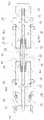
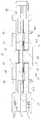
도 1은 본 발명에 따른 동축케이블 커넥터의 모습을 도시한 단면도이고, 도 2는 본 발명에 따른 동축케이블 커넥터의 동작모습을 도시한 단면도인 바, 이를 참조하여 설명한다.1 is a cross-sectional view showing a state of a coaxial cable connector according to the present invention, Figure 2 is a cross-sectional view showing the operation of the coaxial cable connector according to the present invention, will be described with reference to this.
본 발명에 따른 커넥터는, 모듈(20'), 제1,2고정수단(30', 30")과, 모듈(20')의 길이방향을 따라 이동한 제1,2고정수단(30', 30")을 고정하는 스토퍼(40)를 포함한다.The connector according to the present invention includes a module 20 ', first and second fixing means 30' and 30 ", and a first and second fixing means 30 ', which are moved along the longitudinal direction of the
전술한 바와 같이, 모듈(20')은 핀(21')과, 절연부(23') 및 하우징(24')을 포함하되, 상기 하우징(24')의 양단은 제1,2고정수단(30', 30")이 각각 삽입해 맞물리는 제1,2삽입홈(25, 25')을 구비하며, 제1,2삽입홈(25, 25')의 내면에는 제1,3 나사산(26, 26')이 형성된다. 그런데, 제1,2나사산(26, 26') 각각의 나선방향은 상호 역방향으로 형성된다. 즉, 제1나사산(26)이 왼 나선형이라면, 제2나사산(26')은 오른 나선형이 되는 것이다. 한편, 핀(21')의 양단은 제1,2삽입홈(25, 25')으로 인출되어서 외부로 노출되도록 연장되 인입단부(21a, 21b)를 형성한다.As described above, the module 20 'includes a pin 21', an insulator 23 'and a housing 24', both ends of the housing 24 'having first and second fixing means ( 30 ', 30 " are provided with first and
계속해서, 절연부(23')와 하우징(24') 사이에는 핀(21')의 둘레를 이격되게 감싸는 관 형상의 임피던스 매칭부재(60)가 내설 되는데, 임피던스 매칭부재(60)는 제1,2고정수단(30', 30")의 바디(33, 33')와 하우징(24') 간의 통전을 매개한다. 물론, 바디(33, 33')와 하우징(24') 간의 통전은 상호 나사산 결합시 이루어질 것이나, 임피던스 매칭부재(60)는 단순한 통전 이외에 본 발명에 따른 커넥터를 통하는 임피던스의 특성 값을 안정적으로 유지한다.Subsequently, a tubular
참고로, 임피던스를 안정적으로 유지하기 위해서는 전기적인 양 극성이 각각 통과하는 핀(21')과 하우징(24') 간의 간격을 일정하게 유지할 필요가 있는데, 도 2에 도시한 바와 같이 제1,2고정수단(30', 30")이 모듈(20')로부터 이탈하면 핀(21')과 하우징(24')의 일부인 제1,2나사산(26, 26')의 간격이 갑자기 벌어지면서 임피던스의 특성에 변화가 생길 수 있다. 따라서, 임피던스 매칭부재(60)는 제1,2고정수단(30', 30")이 모듈(20')로부터 이탈하더라도 핀(21')과 다른 극성의 전기가 흐르는 도체까지의 거리가 일정하도록 제1,2고정수단(30', 30")의 이동거리에 상응하는 길이로 인출되어 핀(21')을 감싼다.For reference, in order to maintain the impedance stably, it is necessary to maintain a constant distance between the pins 21 'and the housing 24' through which both electric polarities pass, respectively, as shown in FIG. When the fixing means 30 ', 30 "are disengaged from the module 20', the gap between the pin 21 'and the first and
제1,2고정수단(30', 30")은 모듈(20')의 제1,2삽입홈(25, 25')에 각각 삽입 고정되고, 노출된 핀(21')의 인입단부(21a, 21b)가 이동가능하게 맞물리는 통전 대(31, 31')를 각각 내장한다. 또한, 통전대(31, 31')는 바디(33, 33')에 의해 탑재 보호되고, 바디(33)는 절연부재(34)를 매개로 통전대(31, 31')를 단단히 고정한다. 여기서, 통전대(31, 31')의 일단에는 핀(21')의 인입단부(21a, 21b)가 이동가능하게 삽입되는 통전홈(31b, 31b')이 형성되고, 타단에는 동축케이블(10; 도 1 참조)의 내도체(11)가 맞물리는 접속구(31a)가 형성되거나, 통신장비의 접속홈(미도시함)으로 삽입되는 접속돌기(31c)가 형성될 수 있다.The first and second fixing means 30 'and 30 "are inserted into and fixed to the first and
참고로, 본 발명에 따른 실시예의 커넥터는 통신장비와 동축케이블을 연결할 목적으로 제작된 것으로, 모듈(20')의 양단에 제1고정수단(30')이 각각 배치된다면, 이렇게 형성된 커넥터는 한 쌍의 동축케이블을 연결할 목적으로 활용될 수 있을 것이다.For reference, the connector according to the embodiment of the present invention is manufactured for the purpose of connecting the coaxial cable with the communication equipment. If the first fixing means 30 'are disposed at both ends of the module 20', the connector thus formed is It can be used to connect a pair of coaxial cables.
한편, 제1,2삽입홈(25, 25')으로 삽입되는 바디(33, 33')의 외면에는 제1,3나사산(26, 26')에 상응하는 제2,4나사산(35, 35')이 형성된다. 물론, 제2,4나사산(35, 35') 또한 서로 역방향의 나선형을 이루면서 제1,3나사산(26, 26')과 맞물린다.On the other hand, the outer surface of the body (33, 33 ') inserted into the first and second insertion groove (25, 25'), the second, fourth thread (35, 35) corresponding to the first, third thread (26, 26 ') ') Is formed. Of course, the second and
이상 설명한 바와 같은 구조를 갖는 본 발명에 따른 커넥터는 다음과 같은 동작 특성을 갖는다.The connector according to the present invention having the structure as described above has the following operating characteristics.
우선, 전술한 바와 같이, 제1,3나사산(26, 26')과 제2,4나사산(35, 35')이 서로 역방향의 나선형을 이루면서 맞물리고, 모듈(20')을 회전하더라도 동축케이블(10) 또는 통신장비에 단단히 고정된 제1,2고정수단(30', 30")은 회전하지 않게 되므로, 모듈(20')이 회전하면 제1,3나사산(26, 26')과 제2,4나사산(35, 35')의 나 사산 결합이 함께 풀리거나 조여진다. 즉, 제1,2고정수단(30', 30")은 모듈(20')의 회전방향에 따라, 모듈(20')을 중심으로 길이방향을 따라 인출되거나 인입되면서 커넥터의 전체 길이가 조정되는 것이다.First, as described above, the first and
한편, 핀(21')의 인입단부(21a, 21b)는 통전홈(31b, 31b')을 따라 이동하되, 인입단부(21a, 21b)와 통전홈(31b, 31b') 간의 접촉상태는 그대로 유지되므로, 통전대(31, 31')와 핀(21') 간의 전기적인 연결은 제1,2고정수단(30', 30")의 길이조정시에도 항시 유지된다.Meanwhile, the
따라서, 제1,2고정수단(30', 30")에 연결된 동축케이블(10) 또는 통신장비 간의 거리가 단전 없이 길이만 조정되면서, 동축케이블(10)을 절단해서 위상을 조정하는 종래 방식과 유사한 효과를 얻을 수 있다.Therefore, the distance between the coaxial cable 10 or the communication equipment connected to the first and second fixing means 30 ', 30 "is adjusted only the length without disconnection, and the conventional method of cutting the coaxial cable 10 to adjust the phase Similar effects can be obtained.
결국, 본 발명에 따른 커넥터는 모듈(20')을 회전시켜서 제1,2고정수단(30', 30")의 길이를 조정하고, 또한, 길이를 조정하면서 위상을 측정할 수 있으므로, 보다 정밀한 위상 조정이 가능하다.As a result, the connector according to the present invention can rotate the module 20 'to adjust the length of the first and second fixing means 30' and 30 " Phase adjustment is possible.
한편, 위상 측정을 통해 커넥터의 길이가 확정되면, 현재의 길이를 항시 유지시킬 필요가 있다. 이를 위해 본 발명에 따른 커넥터는 스토퍼(40, 40')를 더 포함한다.On the other hand, if the length of the connector is determined through the phase measurement, it is necessary to always maintain the current length. To this end, the connector according to the invention further comprises
스토퍼(40, 40')는 내면에 나사산이 형성된 너트 형상을 이루고, 제1,2삽입홈(25, 25')의 외측에서 제1,2고정수단(30', 30")의 제2,4나사산(35, 35')과 맞물리면서, 스크류 방식으로 위치를 이동시킬 수 있다. 결국, 커넥터의 길이가 확정되면, 현 상태를 유지하기 위해 스토퍼(40, 40')를 각각 회전해 이동시켜서 하우 징(20')과 밀착되도록 배치한다.The
스토퍼(40, 40')는 동축케이블(10) 또는 통신장비에 고정되어 회전하지 않도록 된 제1,2고정수단(30', 30")과 함께 회전 없이 이동하므로, 스토퍼(40, 40')가 하우징(24')과 밀착된 상태라면, 스토퍼(40, 40')를 하우징(24')과 더욱 밀착하는 방향으로는 모듈(20')을 회전시킬 수 없을 것이다.The
미설명된 인출번호 "27"은 "스프링 바디"를 가리키는 것으로, 핀(21')을 감싸듯 이격되게 고정하면서 제1,2삽입홈(25, 25')으로 삽입된 제1,2고정수단(30', 30")에 끼워지면서 탄발력으로 바디(33, 33')와 밀착되어, 모듈(20')과 제1,2고정수단(30', 30") 간의 안정된 결속을 도모한다.Unexplained withdrawal number "27" refers to the "spring body", the first and second fixing means inserted into the first and
미설명된 인출번호 "50"은 "고정관체"를 가리키는 것으로, 제2고정수단(30")이 고정되는 통신장비 등과의 물리적인 결속을 견고히 하는 부재이다.Unexplained withdrawal number "50" refers to the "fixed tube", the second fixing means 30 is a member for securing a physical bond with the communication equipment and the like is fixed.
도 1은 본 발명에 따른 동축케이블 커넥터의 모습을 도시한 단면도이고,1 is a cross-sectional view showing a state of a coaxial cable connector according to the present invention,
도 2는 본 발명에 따른 동축케이블 커넥터의 동작모습을 도시한 단면도이다.2 is a cross-sectional view showing the operation of the coaxial cable connector according to the present invention.
- 첨부도면의 주요부분에 대한 용어설명 --Explanation of terms for main parts of attached drawings-
10; 동축케이블11; 내도체10; Coaxial cable 11; Conductor
12; 절연체13; 외도체12; Insulator 13; Inductor
14; 절연피복20, 20'; 모듈14;
21, 21'; 핀23, 23'; 절연부21, 21 ';
24, 24'; 하우징25, 25'; 제1,2삽입홈24, 24 ';
26, 26'; 제1,3나사산30; 고정수단26, 26 '; First and
30', 30"; 제1,2고정수단31, 31'; 통전대30 ', 30 "; 1st, 2nd fixing means 31, 31'; energizing stand
33, 33'; 바디35, 35'; 제2,4나사산33, 33 ';
40, 40'; 스토퍼60; 인피던스 매칭부재40, 40 ';
Claims (2)
Translated fromKoreanPriority Applications (1)
| Application Number | Priority Date | Filing Date | Title |
|---|---|---|---|
| KR1020080069098AKR101043747B1 (en) | 2008-07-16 | 2008-07-16 | Coaxial cable connector for phase adjustment of RF signal |
Applications Claiming Priority (1)
| Application Number | Priority Date | Filing Date | Title |
|---|---|---|---|
| KR1020080069098AKR101043747B1 (en) | 2008-07-16 | 2008-07-16 | Coaxial cable connector for phase adjustment of RF signal |
Publications (2)
| Publication Number | Publication Date |
|---|---|
| KR20100008552A KR20100008552A (en) | 2010-01-26 |
| KR101043747B1true KR101043747B1 (en) | 2011-06-27 |
Family
ID=41817150
Family Applications (1)
| Application Number | Title | Priority Date | Filing Date |
|---|---|---|---|
| KR1020080069098AExpired - Fee RelatedKR101043747B1 (en) | 2008-07-16 | 2008-07-16 | Coaxial cable connector for phase adjustment of RF signal |
Country Status (1)
| Country | Link |
|---|---|
| KR (1) | KR101043747B1 (en) |
Cited By (2)
| Publication number | Priority date | Publication date | Assignee | Title |
|---|---|---|---|---|
| KR101234659B1 (en) | 2011-08-24 | 2013-02-22 | 주식회사 텔콘 | Rf connecter |
| CN103840340A (en)* | 2014-03-19 | 2014-06-04 | 四川永贵科技有限公司 | Phase-adjustable coaxial connector |
Families Citing this family (6)
| Publication number | Priority date | Publication date | Assignee | Title |
|---|---|---|---|---|
| KR101119170B1 (en)* | 2010-05-10 | 2012-03-20 | 최동욱 | RF coaxial connector's reduce circuit coupling loss |
| RU2677277C2 (en) | 2013-06-07 | 2019-01-16 | Джемвакс Энд Каэл Ко., Лтд. | Biological markers that can be used in cancer immunotherapy |
| KR102123716B1 (en)* | 2016-12-30 | 2020-06-16 | 주식회사 에이플러스알에프 | A Radio Frequency cable connector structure |
| KR102067528B1 (en)* | 2017-10-26 | 2020-01-17 | 주식회사 부흥기술단 | Connector for linking of electric supply and transformation lines |
| KR102085984B1 (en)* | 2018-10-04 | 2020-03-06 | 주식회사 엠피디 | Coaxial cable connector regulable the phase of rf |
| KR102747445B1 (en)* | 2022-11-11 | 2024-12-27 | 한국생산기술연구원 | Connector device for controling cable impedance |
Citations (4)
| Publication number | Priority date | Publication date | Assignee | Title |
|---|---|---|---|---|
| KR20040009217A (en)* | 2002-07-19 | 2004-01-31 | 박세환 | The Production of Plastic Chips With Negative Charge |
| KR100441309B1 (en)* | 2001-11-05 | 2004-07-23 | 주식회사 에이스테크놀로지 | A phase shifter of connector type |
| KR200409217Y1 (en)* | 2005-12-02 | 2006-02-22 | 주식회사 럭스콘테크놀로지 | High Frequency Coaxial Cable Connectors |
| KR20060097671A (en)* | 2005-03-11 | 2006-09-14 | 토마스앤베츠 인터내셔널, 인크. | Coaxial Connector with Cable Fastening Element |
- 2008
- 2008-07-16KRKR1020080069098Apatent/KR101043747B1/ennot_activeExpired - Fee Related
Patent Citations (4)
| Publication number | Priority date | Publication date | Assignee | Title |
|---|---|---|---|---|
| KR100441309B1 (en)* | 2001-11-05 | 2004-07-23 | 주식회사 에이스테크놀로지 | A phase shifter of connector type |
| KR20040009217A (en)* | 2002-07-19 | 2004-01-31 | 박세환 | The Production of Plastic Chips With Negative Charge |
| KR20060097671A (en)* | 2005-03-11 | 2006-09-14 | 토마스앤베츠 인터내셔널, 인크. | Coaxial Connector with Cable Fastening Element |
| KR200409217Y1 (en)* | 2005-12-02 | 2006-02-22 | 주식회사 럭스콘테크놀로지 | High Frequency Coaxial Cable Connectors |
Cited By (2)
| Publication number | Priority date | Publication date | Assignee | Title |
|---|---|---|---|---|
| KR101234659B1 (en) | 2011-08-24 | 2013-02-22 | 주식회사 텔콘 | Rf connecter |
| CN103840340A (en)* | 2014-03-19 | 2014-06-04 | 四川永贵科技有限公司 | Phase-adjustable coaxial connector |
Also Published As
| Publication number | Publication date |
|---|---|
| KR20100008552A (en) | 2010-01-26 |
Similar Documents
| Publication | Publication Date | Title |
|---|---|---|
| KR101043747B1 (en) | Coaxial cable connector for phase adjustment of RF signal | |
| US8134424B2 (en) | Electrostatic connector | |
| US7811133B2 (en) | Shielded electrical connector with a spring arrangement | |
| EP2636105B1 (en) | Electrical connector with grounding member | |
| JP6058033B2 (en) | How to check the connection status of antenna and cable | |
| US12176133B2 (en) | Inductive component and method for producing the same | |
| CN101036264B (en) | Antenna feed structure | |
| US20130090010A1 (en) | Surge Protector Components Having a Plurality of Spark Gap Members Between a Central Conductor and an Outer Housing | |
| US20110215986A1 (en) | Antenna Assembly | |
| KR102123716B1 (en) | A Radio Frequency cable connector structure | |
| US9875845B2 (en) | Coupling device and coupling assembly for the contact-free transmission of data signals and method for the transmission of data signals | |
| US7538743B1 (en) | Balanced and shortened antennas | |
| US7101203B2 (en) | Method and apparatus for electronically interconnecting high voltage modules positioned in relatively close proximity | |
| KR200478019Y1 (en) | Adjustable matched cable assemblies and signal transmission system thereof | |
| US9928941B2 (en) | Impedance matching device | |
| US10436816B2 (en) | Test coaxial connector | |
| US10062980B2 (en) | Field terminable plug assembly | |
| JP2017175299A (en) | Wire antenna device | |
| KR20150051721A (en) | Connecting apparatus of cable connector for twist prevent | |
| EP2157667B1 (en) | Method for supplying power over a coaxial cable and corresponding connector | |
| US20250219385A1 (en) | Cable splicing device having a coupling portion that is configured to move relative to a conducting portion so as to improve installation versatility and/or electrical performance | |
| US20020106936A1 (en) | Connection element for connecting a semi-rigid coaxial conductor | |
| JP3214259U (en) | Connector for cable tester cord | |
| WO2014052325A1 (en) | Coaxial cable connector, such as for use with leaky feeder communications systems, and methods therefor |
Legal Events
| Date | Code | Title | Description |
|---|---|---|---|
| A201 | Request for examination | ||
| PA0109 | Patent application | St.27 status event code:A-0-1-A10-A12-nap-PA0109 | |
| PA0201 | Request for examination | St.27 status event code:A-1-2-D10-D11-exm-PA0201 | |
| D13-X000 | Search requested | St.27 status event code:A-1-2-D10-D13-srh-X000 | |
| PG1501 | Laying open of application | St.27 status event code:A-1-1-Q10-Q12-nap-PG1501 | |
| D14-X000 | Search report completed | St.27 status event code:A-1-2-D10-D14-srh-X000 | |
| E902 | Notification of reason for refusal | ||
| PE0902 | Notice of grounds for rejection | St.27 status event code:A-1-2-D10-D21-exm-PE0902 | |
| E13-X000 | Pre-grant limitation requested | St.27 status event code:A-2-3-E10-E13-lim-X000 | |
| P11-X000 | Amendment of application requested | St.27 status event code:A-2-2-P10-P11-nap-X000 | |
| P13-X000 | Application amended | St.27 status event code:A-2-2-P10-P13-nap-X000 | |
| E90F | Notification of reason for final refusal | ||
| PE0902 | Notice of grounds for rejection | St.27 status event code:A-1-2-D10-D21-exm-PE0902 | |
| T11-X000 | Administrative time limit extension requested | St.27 status event code:U-3-3-T10-T11-oth-X000 | |
| P11-X000 | Amendment of application requested | St.27 status event code:A-2-2-P10-P11-nap-X000 | |
| P13-X000 | Application amended | St.27 status event code:A-2-2-P10-P13-nap-X000 | |
| E701 | Decision to grant or registration of patent right | ||
| PE0701 | Decision of registration | St.27 status event code:A-1-2-D10-D22-exm-PE0701 | |
| GRNT | Written decision to grant | ||
| PR0701 | Registration of establishment | St.27 status event code:A-2-4-F10-F11-exm-PR0701 | |
| PR1002 | Payment of registration fee | St.27 status event code:A-2-2-U10-U11-oth-PR1002 Fee payment year number:1 | |
| PG1601 | Publication of registration | St.27 status event code:A-4-4-Q10-Q13-nap-PG1601 | |
| PN2301 | Change of applicant | St.27 status event code:A-5-5-R10-R13-asn-PN2301 St.27 status event code:A-5-5-R10-R11-asn-PN2301 | |
| FPAY | Annual fee payment | Payment date:20140612 Year of fee payment:4 | |
| PR1001 | Payment of annual fee | St.27 status event code:A-4-4-U10-U11-oth-PR1001 Fee payment year number:4 | |
| FPAY | Annual fee payment | Payment date:20150615 Year of fee payment:5 | |
| PR1001 | Payment of annual fee | St.27 status event code:A-4-4-U10-U11-oth-PR1001 Fee payment year number:5 | |
| FPAY | Annual fee payment | Payment date:20160610 Year of fee payment:6 | |
| PR1001 | Payment of annual fee | St.27 status event code:A-4-4-U10-U11-oth-PR1001 Fee payment year number:6 | |
| P22-X000 | Classification modified | St.27 status event code:A-4-4-P10-P22-nap-X000 | |
| PN2301 | Change of applicant | St.27 status event code:A-5-5-R10-R13-asn-PN2301 St.27 status event code:A-5-5-R10-R11-asn-PN2301 | |
| PN2301 | Change of applicant | St.27 status event code:A-5-5-R10-R13-asn-PN2301 St.27 status event code:A-5-5-R10-R11-asn-PN2301 | |
| PR1001 | Payment of annual fee | St.27 status event code:A-4-4-U10-U11-oth-PR1001 Fee payment year number:7 | |
| PR1001 | Payment of annual fee | St.27 status event code:A-4-4-U10-U11-oth-PR1001 Fee payment year number:8 | |
| R18-X000 | Changes to party contact information recorded | St.27 status event code:A-5-5-R10-R18-oth-X000 | |
| FPAY | Annual fee payment | Payment date:20190605 Year of fee payment:9 | |
| PR1001 | Payment of annual fee | St.27 status event code:A-4-4-U10-U11-oth-PR1001 Fee payment year number:9 | |
| PC1903 | Unpaid annual fee | St.27 status event code:A-4-4-U10-U13-oth-PC1903 Not in force date:20200617 Payment event data comment text:Termination Category : DEFAULT_OF_REGISTRATION_FEE | |
| R18-X000 | Changes to party contact information recorded | St.27 status event code:A-5-5-R10-R18-oth-X000 | |
| PC1903 | Unpaid annual fee | St.27 status event code:N-4-6-H10-H13-oth-PC1903 Ip right cessation event data comment text:Termination Category : DEFAULT_OF_REGISTRATION_FEE Not in force date:20200617 |