KR101042323B1 - Polishing unit and substrate polishing apparatus having the same - Google Patents
Polishing unit and substrate polishing apparatus having the sameDownload PDFInfo
- Publication number
- KR101042323B1 KR101042323B1KR1020090073476AKR20090073476AKR101042323B1KR 101042323 B1KR101042323 B1KR 101042323B1KR 1020090073476 AKR1020090073476 AKR 1020090073476AKR 20090073476 AKR20090073476 AKR 20090073476AKR 101042323 B1KR101042323 B1KR 101042323B1
- Authority
- KR
- South Korea
- Prior art keywords
- rotating shaft
- unit
- shaft
- polishing
- vertical arm
- Prior art date
- Legal status (The legal status is an assumption and is not a legal conclusion. Google has not performed a legal analysis and makes no representation as to the accuracy of the status listed.)
- Active
Links
- 238000005498polishingMethods0.000titleclaimsabstractdescription109
- 239000000758substrateSubstances0.000titleclaimsabstractdescription68
- 238000003825pressingMethods0.000claimsabstractdescription59
- 239000000126substanceSubstances0.000claimsabstractdescription13
- 238000000034methodMethods0.000claimsdescription44
- 239000011553magnetic fluidSubstances0.000claimsdescription24
- 239000000463materialSubstances0.000claimsdescription13
- 230000002265preventionEffects0.000claimsdescription13
- 230000008878couplingEffects0.000claimsdescription11
- 238000010168coupling processMethods0.000claimsdescription11
- 238000005859coupling reactionMethods0.000claimsdescription11
- 239000011347resinSubstances0.000claimsdescription2
- 229920005989resinPolymers0.000claimsdescription2
- 238000007789sealingMethods0.000claims2
- 230000000149penetrating effectEffects0.000claims1
- 238000007517polishing processMethods0.000abstractdescription33
- 235000012431wafersNutrition0.000description94
- 238000011084recoveryMethods0.000description65
- 239000007788liquidSubstances0.000description38
- 238000004140cleaningMethods0.000description20
- 239000012530fluidSubstances0.000description20
- 238000011282treatmentMethods0.000description15
- 239000000443aerosolSubstances0.000description7
- 230000003750conditioning effectEffects0.000description5
- 239000002245particleSubstances0.000description5
- 239000004065semiconductorSubstances0.000description5
- 230000003028elevating effectEffects0.000description4
- 230000005484gravityEffects0.000description4
- 230000007423decreaseEffects0.000description3
- 238000001035dryingMethods0.000description3
- 238000002347injectionMethods0.000description3
- 239000007924injectionSubstances0.000description3
- 238000000926separation methodMethods0.000description3
- 239000002002slurrySubstances0.000description3
- 239000007921spraySubstances0.000description3
- 239000000284extractSubstances0.000description2
- 230000001965increasing effectEffects0.000description2
- 238000004519manufacturing processMethods0.000description2
- 239000007769metal materialSubstances0.000description2
- 238000005507sprayingMethods0.000description2
- 239000008186active pharmaceutical agentSubstances0.000description1
- 238000005452bendingMethods0.000description1
- 238000004891communicationMethods0.000description1
- 238000005520cutting processMethods0.000description1
- 230000003247decreasing effectEffects0.000description1
- 238000005137deposition processMethods0.000description1
- 238000005530etchingMethods0.000description1
- 239000010419fine particleSubstances0.000description1
- 238000000227grindingMethods0.000description1
- 210000004185liverAnatomy0.000description1
- 238000010297mechanical methods and processMethods0.000description1
- 238000000206photolithographyMethods0.000description1
- 239000010409thin filmSubstances0.000description1
- WFKWXMTUELFFGS-UHFFFAOYSA-NtungstenChemical compound[W]WFKWXMTUELFFGS-UHFFFAOYSA-N0.000description1
- 229910052721tungstenInorganic materials0.000description1
- 239000010937tungstenSubstances0.000description1
- 238000004148unit processMethods0.000description1
- 238000005406washingMethods0.000description1
Images


Classifications
- B—PERFORMING OPERATIONS; TRANSPORTING
- B24—GRINDING; POLISHING
- B24B—MACHINES, DEVICES, OR PROCESSES FOR GRINDING OR POLISHING; DRESSING OR CONDITIONING OF ABRADING SURFACES; FEEDING OF GRINDING, POLISHING, OR LAPPING AGENTS
- B24B37/00—Lapping machines or devices; Accessories
- B24B37/04—Lapping machines or devices; Accessories designed for working plane surfaces
- B—PERFORMING OPERATIONS; TRANSPORTING
- B24—GRINDING; POLISHING
- B24B—MACHINES, DEVICES, OR PROCESSES FOR GRINDING OR POLISHING; DRESSING OR CONDITIONING OF ABRADING SURFACES; FEEDING OF GRINDING, POLISHING, OR LAPPING AGENTS
- B24B31/00—Machines or devices designed for polishing or abrading surfaces on work by means of tumbling apparatus or other apparatus in which the work and/or the abrasive material is loose; Accessories therefor
- B24B31/12—Accessories; Protective equipment or safety devices; Installations for exhaustion of dust or for sound absorption specially adapted for machines covered by group B24B31/00
Landscapes
- Engineering & Computer Science (AREA)
- Mechanical Engineering (AREA)
- Mechanical Treatment Of Semiconductor (AREA)
- Cleaning Or Drying Semiconductors (AREA)
Abstract
Translated fromKoreanDescription
Translated fromKorean본 발명은 반도체 제조 장치 및 방법에 관한 것으로서, 보다 상세하게는 반도체 기판을 매엽식 처리 방식으로 연마 및 세정하는 기판 처리 장치 및 방법에 관한 것이다.BACKGROUND OF THE INVENTION 1. Field of the Invention The present invention relates to a semiconductor manufacturing apparatus and method, and more particularly, to a substrate processing apparatus and method for polishing and cleaning a semiconductor substrate by a sheet-fed process.
일반적으로 반도체 소자의 제조 공정은 박막의 형성 및 적층을 위해 증착 공정, 사진 공정, 식각 공정 등 다수의 단위 공정들을 반복 수행해야만 한다. 웨이퍼 상에 요구되는 소정의 회로 패턴이 형성될 때까지 이들 공정은 반복되며, 회로 패턴이 형성된 후 웨이퍼의 표면에는 많은 굴곡이 생기게 된다. 최근 반도체 소자는 고집적화에 따라 그 구조가 다층화되며, 웨이퍼 표면의 굴곡의 수와 이들 사이의 단차가 증가하고 있다. 웨이퍼 표면의 비평탄화는 사진 공정에서 디포커스(Defocus) 등의 문제를 발생시키므로 웨이퍼의 표면을 평탄화하기 위해 주기적으로 웨이퍼 표면을 연마하여야 한다.In general, a semiconductor device manufacturing process must repeatedly perform a plurality of unit processes such as a deposition process, a photo process, and an etching process to form and stack thin films. These processes are repeated until the desired circuit pattern is formed on the wafer, and after the circuit pattern is formed, a lot of bending occurs on the surface of the wafer. In recent years, as semiconductor devices become highly integrated, their structures are multilayered, and the number of bends on the surface of the wafer and the step between them are increasing. Unplanarization of the wafer surface causes problems such as defocus in the photolithography process, and thus the wafer surface must be polished periodically to planarize the surface of the wafer.
웨이퍼의 표면을 평탄화하기 위해 다양한 표면 평탄화 기술이 있으나 이 중 좁은 영역뿐만 아니라 넓은 영역의 평탄화에 있어서도 우수한 평탄도를 얻을 수 있 는 화학적 기계적 연마(Chemical Mechanical Polishing : CMP) 장치가 주로 사용된다. 화학적 기계적 연마 장치는 텅스텐이나 산화물 등이 입혀진 웨이퍼의 표면을 기계적 마찰에 의해 연마시킴과 동시에 화학적 연마재에 의해 연마시키는 장치로서, 아주 미세한 연마를 가능하게 한다.Various surface planarization techniques are used to planarize the surface of the wafer, but chemical mechanical polishing (CMP) apparatuses, which can obtain excellent flatness not only for narrow areas but also for wide areas, are mainly used. The chemical mechanical polishing apparatus is an apparatus for polishing a surface of a wafer coated with tungsten, an oxide, or the like by mechanical friction and polishing with a chemical abrasive, and enables very fine polishing.
웨이퍼 연마시, 연마 장치는 연마 패드의 상면에 웨이퍼를 배치시킨 후 웨이퍼를 연마 패드에 가압하면서 회전시켜 웨이퍼를 연마한다. 연마 공정시, 웨이퍼를 고정하는 고정부재가 회전하면서 웨이퍼의 연마가 이루어지므로, 고정부재의 회전에 의해 고정부재 내부에서 발생된 이물이 연마 패드 측으로 떨어질 수 있고, 이로 인해, 연마 불량이 발생한다.In wafer polishing, the polishing apparatus places a wafer on an upper surface of the polishing pad and then rotates the wafer while pressing the polishing pad to polish the wafer. During the polishing process, since the wafer is polished while the fixing member holding the wafer rotates, foreign matter generated inside the fixing member may fall to the polishing pad side due to the rotation of the fixing member, which causes polishing failure.
본 발명의 목적은 제품 효율을 향상시킬 수 있는 연마 유닛을 제공하는 것이다.It is an object of the present invention to provide a polishing unit capable of improving product efficiency.
또한, 본 발명의 목적은 상기한 연마 유닛을 구비하는 기판 연마 장치를 제공하는 것이다.It is also an object of the present invention to provide a substrate polishing apparatus having the polishing unit described above.
상기한 본 발명의 목적을 실현하기 위한 하나의 특징에 따른 연마 유닛은, 가압부, 수직암부, 스윙암부 및 구동부로 이루어진다.The polishing unit according to one feature for realizing the above object of the present invention comprises a pressing portion, a vertical arm portion, a swing arm portion and a driving portion.
가압부는 기판의 표면을 연마하는 연마 패드를 구비하며, 중심축을 기준으로 회전 가능하다. 수직암부는 기둥 형상을 갖고, 일 단부가 상기 가압부에 결합되며, 상기 가압부를 회전시킨다. 스윙암부는 상기 수직암부와 결합하고, 상기 수직암부의 길이 방향과 직교하는 방향으로 연장되며, 스윙 가능하다. 구동부는 상기 스윙암부와 결합하고, 상기 스윙암부 및 상기 수직암부에 각각 회전력을 제공한다.The pressing portion has a polishing pad for polishing the surface of the substrate and is rotatable about a central axis. The vertical arm portion has a columnar shape, one end is coupled to the pressing portion, and rotates the pressing portion. The swing arm portion is coupled to the vertical arm portion, extends in a direction orthogonal to the longitudinal direction of the vertical arm portion, and is swingable. The driving unit is coupled to the swing arm unit and provides rotational force to the swing arm unit and the vertical arm unit, respectively.
구체적으로, 상기 수직암부는 회전축, 고정축, 적어도 하나의 베어링 및 자석을 구비한다. 회전축은 상기 가압부에 고정 결합되고, 상기 가압부를 회전시킨다. 고정축은 상기 회전축으로부터 이격되어 상기 회전축을 둘러싼다. 베어링은 상기 회전축과 상기 고정축 사이에 개재되어 회전축을 둘러싸고, 상기 회전축의 위치를 고정시킨다. 자석은 상기 회전축과 상기 고정축 사이에서 상기 베어링의 아래에 구비되고, 상기 회전축을 둘러싼다.Specifically, the vertical arm portion has a rotating shaft, a fixed shaft, at least one bearing and a magnet. The rotating shaft is fixedly coupled to the pressing portion and rotates the pressing portion. The fixed shaft is spaced apart from the rotating shaft and surrounds the rotating shaft. A bearing is interposed between the rotating shaft and the fixed shaft to surround the rotating shaft and fix the position of the rotating shaft. A magnet is provided below the bearing between the rotating shaft and the fixed shaft, and surrounds the rotating shaft.
또한, 상기한 본 발명의 목적을 실현하기 위한 하나의 특징에 따른 연마 유닛은 가압부, 수직암부 및 구동부로 이루어진다.In addition, the polishing unit according to one feature for realizing the object of the present invention described above is composed of a pressing portion, a vertical arm portion and a driving portion.
가압부는 기판의 표면을 연마하는 연마 패드를 구비하며, 중심축을 기준으로 회전 가능하다. 수직암부는 기둥 형상을 갖고, 일 단부가 상기 가압부에 분리 가능하게 결합되며, 상기 가압부를 회전시킨다. 구동부는 상기 수직암부에 회전력을 제공한다. 구체적으로, 상기 수직암부는 고정축, 회전축, 및 자성 유체를 구비한다. 고정축은 관통홀이 형성된 하면, 및 상기 하면의 단부로부터 수직하게 연장되어 중공형의 통 형상을 갖는 측벽을 갖고, 상면이 개구된다. 회전축은 상기 고정축 내에서 상기 고정축으로부터 이격되어 설치되고, 하단부가 상기 관통홀을 관통하여 상기 가압부에 고정 결합되며, 회전하여 상기 가압부를 회전시키고, 외주면에 단턱이 형성된다. 자성 유체는 상기 고정축 내에서 상기 회전축과 상기 고정축 사이에 개 재되고, 상기 고정축의 하면과 상기 회전축의 단턱에 의해 정의되는 공간에 주입되어 상기 회전축과 접하며, 상기 회전축을 둘러싸고, 상기 관통홀을 통해 외부로 노출된다.The pressing portion has a polishing pad for polishing the surface of the substrate and is rotatable about a central axis. The vertical arm portion has a columnar shape, one end of which is detachably coupled to the pressing portion, and rotates the pressing portion. The driving unit provides a rotational force to the vertical arm. In detail, the vertical arm part includes a fixed shaft, a rotating shaft, and a magnetic fluid. The fixed shaft has a lower surface on which a through hole is formed and a side wall extending vertically from an end of the lower surface and having a hollow cylindrical shape, and the upper surface is opened. The rotating shaft is installed spaced apart from the fixed shaft in the fixed shaft, the lower end penetrates the through hole and is fixedly coupled to the pressing unit, rotates to rotate the pressing unit, and a stepped portion is formed on an outer circumferential surface. A magnetic fluid is interposed between the rotating shaft and the fixed shaft within the fixed shaft, and injected into a space defined by the lower surface of the fixed shaft and the stepped portion of the rotating shaft to contact the rotating shaft and surround the rotating shaft. Exposed to the outside through.
또한, 상기한 본 발명의 목적을 실현하기 위한 하나의 특징에 따른 기판 연마 장치는 기판 지지유닛 및 연마 유닛으로 이루어진다.In addition, the substrate polishing apparatus according to one feature for realizing the above object of the present invention comprises a substrate supporting unit and a polishing unit.
기판 지지유닛은 기판이 안착되고, 회전 가능하다. 연마 유닛은 상기 기판 지지유닛의 일측에 설치되고, 상기 기판의 표면을 연마한다. 구체적으로, 상기 연마 유닛은 가압부, 수직암부, 스윙암부 및 구동부를 구비한다. 가압부는 상기 기판의 표면을 연마 패드를 구비하며, 중심축을 기준으로 회전 가능하다. 수직암부는 하단부가 상기 가압부의 상면에 고정 결합되어 상기 가압부를 회전시키는 회전축, 상기 회전축으로부터 이격되어 상기 회전축을 둘러싸는 고정축, 상기 회전축과 상기 고정축 사이에 개재되어 회전축을 둘러싸는 적어도 하나의 베어링, 및 상기 회전축과 상기 고정축 사이에서 상기 베어링의 아래에 설치되어 상기 회전축을 둘러싸는 자석을 구비한다. 스윙암부는 상기 수직암부와 결합하고, 상기 수직암부의 길이 방향과 직교하는 방향으로 연장되며, 스윙 가능하다. 구동부는 상기 스윙암부와 결합하고, 상기 스윙암부 및 상기 수직암부에 각각 회전력을 제공한다.The substrate support unit is mounted on the substrate and rotatable. The polishing unit is installed on one side of the substrate support unit, and polishes the surface of the substrate. Specifically, the polishing unit includes a pressing portion, a vertical arm portion, a swing arm portion and a driving portion. The pressing unit has a polishing pad on the surface of the substrate, and is rotatable about a central axis. The vertical arm portion has a lower end is fixedly coupled to the upper surface of the pressing portion to rotate the pressing portion, a fixed shaft spaced apart from the rotating shaft surrounding the rotating shaft, at least one interposed between the rotating shaft and the fixed shaft surrounding the rotating shaft A bearing, and a magnet disposed below the bearing between the rotating shaft and the fixed shaft to surround the rotating shaft. The swing arm portion is coupled to the vertical arm portion, extends in a direction orthogonal to the longitudinal direction of the vertical arm portion, and is swingable. The driving unit is coupled to the swing arm unit and provides rotational force to the swing arm unit and the vertical arm unit, respectively.
상술한 본 발명에 따르면, 고정축 내에서 발생된 이물이 자석 또는 자성 유체 측으로 유도되므로, 수직암부는 내부의 이물이 외부로 유출되는 것을 방지할 수 있다. 이에 따라, 연마 유닛은 수직암부내의 이물이 연마 공정 중인 기판에 떨어지 는 것을 방지하고, 제품의 수율을 향상시킬 수 있다.According to the present invention described above, since the foreign matter generated in the fixed shaft is guided to the magnet or magnetic fluid side, the vertical arm portion can prevent the foreign matter inside from leaking to the outside. Accordingly, the polishing unit can prevent foreign matter in the vertical arm portion from falling on the substrate during the polishing process, and improve the yield of the product.
이하, 첨부한 도면들을 참조하여 본 발명의 바람직한 실시예를 보다 상세하게 설명한다. 이하에서는, 웨이퍼를 반도체 기판의 일례로 설명하나, 본 발명의 기술적 사상과 범위는 이에 한정되지 않는다.Hereinafter, preferred embodiments of the present invention will be described in detail with reference to the accompanying drawings. Hereinafter, the wafer will be described as an example of a semiconductor substrate, but the spirit and scope of the present invention are not limited thereto.
도 1은 본 발명의 일 실시예에 따른 매엽식 기판 처리 시스템을 개략적으로 나타낸 도면이다.1 is a view schematically showing a sheet type substrate processing system according to an embodiment of the present invention.
도 1을 참조하면, 본 발명의 기판 처리 시스템(2000)은 로딩/언로딩부(10), 인덱스 로봇(Index Robot)(20), 버퍼부(30), 메인 이송 로봇(Main Transfer Robot)(50), 다수의 기판 연마부(1000) 및 제어부(60)를 포함할 수 있다.Referring to FIG. 1, the
상기 로딩/언로딩부(10)는 다수의 로드 포트(11a, 11b, 11c, 11d)를 포함한다. 이 실시예에 있어서, 상기 로딩/언로딩부(11)는 네 개의 로드 포트(11a, 11b, 11c, 11d)를 구비하나, 상기 로드 포트(11a, 11b, 11c, 11d)의 개수는 상기 기판 처리 시스템(2000)의 공정 효율 및 풋 프린트(Foot print) 조건에 따라 증가하거나 감소할 수도 있다.The loading /
상기 로드 포트들(11a, 11b, 11c, 11d)에는 웨이퍼들이 수납되는 풉들(Front Open Unified Pods: FOUPs)(12a, 12b, 12c, 12d)이 안착된다. 각 풉(12a, 12b, 12c, 12d)은 웨이퍼들을 지면에 대해 수평하게 배치한 상태로 수납하기 위한 다수의 슬롯이 형성된다. 상기 풉(12a, 12b, 12c, 12d)에는 각 기판 연마부(1000)에서 처리가 완료된 웨이퍼들 또는 상기 각 기판 연마부(1000)에 투입할 웨이퍼들을 수납한다. 이하, 설명의 편의를 위해, 상기 각 기판 연마부(1000)에 의해 처리가 완료된 웨이퍼를 가공 웨이퍼라 하고, 아직 처리되지 않은 웨이퍼를 원시 웨이퍼라 한다.Front open unified pods (FOUPs) 12a, 12b, 12c, and 12d in which wafers are accommodated are mounted in the
상기 로딩/언로딩부(11)와 상기 버퍼부(30) 사이에는 제1 이송 통로(41)가 형성되고, 상기 제1 이송 통로(41)에는 제1 이송 레일(42)이 설치된다. 상기 인덱스 로봇(20)은 상기 제1 이송 레일(42)에 설치되고, 상기 제1 이송 레일(42)을 따라 이동하면서 상기 로딩/언로딩부(11)와 상기 버퍼부(30) 간에 웨이퍼들을 이송한다. 즉, 상기 인덱스 로봇(20)은 상기 로딩/언로딩부(11)에 안착된 풉(12a, 12b, 12c, 12d)으로부터 적어도 한 매의 원시 웨이퍼를 인출하여 상기 버퍼부(30)에 적재한다. 또한, 상기 인덱스 로봇(20)은 상기 버퍼부(30)로부터 적어도 한 매의 가공 웨이퍼를 인출하여 상기 로딩/언로딩부(11)에 안착된 풉(12a, 12b, 12c, 12d)에 적재한다.A
한편, 상기 버퍼부(30)는 상기 제1 이송 통로(41)의 일측에 설치된다. 상기 버퍼부(30)는 상기 인덱스 로봇(20)에 의해 이송된 원시 웨이퍼들을 수납하고, 상기 기판 연마부들에서 처리된 가공 웨이퍼들을 수납한다.On the other hand, the
상기 메인 이송 로봇(50)은 제2 이송 통로(43)에 설치된다. 상기 제2 이송 통로(43)에는 제2 이송 레일(44)이 구비되고, 상기 제2 이송 레일(44)에는 상기 메인 이송 로봇(50)이 설치된다. 상기 메인 이송 로봇(50)은 상기 제2 이송 레일(44)을 따라 이동하면서, 상기 버퍼부(30)와 상기 기판 연마부들 간에 웨이퍼를 이송한 다. 즉, 상기 메인 이송 로봇(50)은 상기 버퍼부(30)로부터 적어도 한 매의 원시 웨이퍼를 인출하여 상기 기판 연마부(1000)에 제공하고, 상기 기판 연마부(1000)에서 처리된 웨이퍼, 즉 가공 웨이퍼를 상기 버퍼부(30)에 적재한다.The
상기 제2 이송 통로(43)의 양측에는 상기 기판 연마부들이 배치되고, 각 기판 연마부(1000)는 상기 원시 웨이퍼를 연마 및 세정하여 상기 가공 웨이퍼로 만든다. 상기 기판 연마부들은 적어도 두 개 이상의 기판 연마부가 상기 제2 이송 통로(43)를 사이에 두고 서로 마주하게 배치된다. 본 발명의 일례로, 기판 연마부들은 평면상에서 볼 때 상기 제2 이송 통로(43) 양측에 각각 두 개씩 상기 제2 이송 통로(43)를 따라 병렬 배치되나, 상기 제2 이송 통로(43)의 양 측에 각각 배치되는 기판 연마부(1000)의 개수는 상기 기판 연마 시스템(2000)의 공정 효율 및 풋 프린트에 따라 증가하거나 감소할 수도 있다.The substrate polishing units are disposed at both sides of the
한편, 각 기판 연마부(1000)는 상기 제어부(60)와 연결되고, 상기 제어부(60)의 제어에 따라 원시 웨이퍼를 연마 및 세정한다. 즉, 상기 제어부(60)는 상기 기판 연마부(1000)를 제어하여 각 기판 연마부(1000)의 연마 공정을 제어한다.Meanwhile, each
이하, 도면을 참조하여 상기 기판 연마부(1000)의 구성에 대해 구체적으로 설명한다.Hereinafter, the structure of the
도 2는 도 1에 도시된 기판 연마부를 나타낸 사시도이고, 도 3은 도 2에 도시된 기판 지지유닛 및 용기 유닛을 구체적으로 나타낸 부분 절개 사시도이다.2 is a perspective view illustrating the substrate polishing unit illustrated in FIG. 1, and FIG. 3 is a partially cut perspective view illustrating the substrate support unit and the container unit illustrated in FIG. 2.
도 1 내지 도 3을 참조하면, 상기 기판 연마 시스템(2000)은 웨이퍼(70)의 상면을 연마하는 연마 공정 및 연마 공정 후 웨이퍼(70)의 표면을 세정하는 세정 공정을 하나의 기판 연마부(1000) 내에서 순차적으로 진행할 수 있다.1 to 3, the
구체적으로, 상기 기판 연마부(1000)는 기판 지지유닛(100), 용기 유닛(bowl unit)(200), 연마 유닛(300), 제1 및 제2 처리액 공급 유닛(410, 420), 브러쉬 유닛(510), 에어로졸 유닛(520) 및 패드 컨디셔닝 유닛(600)을 포함할 수 있다.In detail, the
상기 기판 지지유닛(100)은 상기 메인 이송 로봇(50)으로부터 이송된 웨이퍼(70)가 안착된다. 상기 기판 지지 유닛(100)은 상기 웨이퍼(70)의 연마 공정과 세정 공정이 이루어지는 동안 상기 웨이퍼(70)를 지지 및 고정시킨다. 상기 기판 지지 유닛(100)은 상기 웨이퍼(70)가 안착되는 스핀 헤드(110), 상기 스핀 헤드(110)를 지지하는 지지부(120), 및 회전력을 제공하는 스핀 구동부(미도시)를 포함할 수 있다.The
상기 스핀 헤드(110)는 평면상에서 볼 때, 대체로 원 형상을 갖고, 상면으로부터 하면으로 갈수록 점차 폭이 감소한다. 본 발명의 일례로, 상기 스핀 헤드(110)는 상기 웨이퍼(70)를 지지하는 상면의 면적이 상기 웨이퍼(70)의 면적 보다 작다. 따라서, 측면에서 볼 때 상기 스핀 헤드(110)에 안착된 웨이퍼(70)는 단부가 상기 스핀 헤드(110) 상면의 단부보다 외측으로 돌출된다.The
상기 스핀 헤드(110)의 아래에는 상기 지지부(120)가 설치되고, 상기 지지부(120)는 상기 스핀 구동부(130)와 연결된다. 상기 지지부(120)는 대체로 원기둥 형상을 가지며, 상기 스핀 헤드(110)와 결합한다. 상기 스핀 구동부는 상기 지지부(120)를 회전시키고, 상기 지지부(120)의 회전력은 상기 스핀 헤드(110)에 전달 되어 상기 스핀 헤드(110)가 회전된다. 연마 공정 및 세정 공정이 이루어지는 동안, 상기 스핀 헤드(110)는 상면에 상기 기판(70)을 고정시킨 상태에서 상기 스핀 구동부로부터 제공되는 회전력에 의해 회전한다.The
상기 기판 지지 유닛(100)은 상기 용기 유닛(200) 내부에 수용된다. 상기 용기 유닛(200)은 제1 및 제2 처리 용기(process bowl)(210, 220), 제1 및 제2 회수통(recovery vat)(230, 240), 제1 및 제2 회수관(251, 252), 및 승강부재(260)를 포함할 수 있다.The
구체적으로, 상기 제1 및 제2 처리 용기(210, 220)는 상기 기판 지지유닛(100)을 둘러싸고, 상기 웨이퍼(70)의 연마 공정 및 세정 공정이 이루어지는 공정 공간을 제공한다. 상기 제1 및 제2 처리 용기(210, 220)는 각각 상부가 개방되며, 상기 제1 및 제2 처리 용기(210, 220)의 개방된 상부를 통해 상기 스핀 헤드(110)가 노출된다. 이 실시예에 있어서, 상기 제1 및 제2 처리 용기(210, 220)는 원형의 링 형상을 가지나, 상기 제1 및 제2 처리 용기(210, 220)의 형상은 이에 국한되지 않고 다양한 형상을 가질 수 있다.In detail, the first and
구체적으로, 상기 제1 처리 용기(210)는 측벽(211), 상판(212) 및 가이드부(213)를 포함할 수 있다. 상기 측벽(211)은 대체로 원형의 링 형상을 갖고, 상기 기판 지지 유닛(100)을 둘러싼다.In detail, the
상기 측벽(211)의 상단부는 상기 상판(212)과 연결된다. 상기 상판(212)은 상기 측벽(211)으로부터 연장되어 형성되고, 상기 측벽(211)으로부터 멀어질수록 상향 경사진 경사면으로 이루어진다. 상기 상판(212)은 대체로 원형의 링 형상을 갖고, 평면상에서 볼 때 상기 스핀 헤드(110)로부터 이격되어 상기 스핀 헤드(110)를 둘러싼다.An upper end of the
상기 가이드부(213)는 제1 및 제2 가이드 벽(213a, 213b)을 포함한다. 상기 제1 가이드 벽(213a)은 상기 측벽(211)의 내벽으로부터 돌출되어 상기 상판(212)과 마주하며, 상기 측벽으로부터 멀어질수록 하향 경사진 경사면으로 이루어지고, 원형의 링 형상을 갖는다. 상기 제2 가이드 벽(213b)은 상기 제1 가이드 벽(213a)으로부터 아래로 수직하게 연장되고, 상기 측벽(211)과 마주하며, 원형의 링 형상을 갖는다. 상기 가이드부(213)는 상기 웨이퍼(70)의 연마 공정중 상기 제1 처리 용기(210)의 측벽(211)과 상판(212)의 내면들측으로 비산된 처리액이 상기 제1 회수통(230) 측으로 흐르도록 가이드한다.The
상기 제1 처리 용기(210)의 외측에는 상기 제2 처리 용기(220)가 설치된다. 상기 제2 처리 용기(220)는 상기 제1 처리 용기(210)를 둘러싸고, 상기 제1 처리 용기(210)보다 큰 크기를 갖는다.The
구체적으로, 상기 제2 처리 용기(220)는 측벽(221) 및 상판(222)을 포함할 수 있다. 상기 측벽(221)은 대체로 원형의 링 형상을 갖고, 상기 제1 처리 용기(210)의 측벽(211)을 둘러싼다. 상기 측벽(221)은 상기 제1 처리 용기(210)의 측벽(211)과 이격되어 위치하며, 상기 제1 처리 용기(210)와 연결된다.In detail, the
상기 측벽(221)의 상단부는 상기 상판(222)과 연결된다. 상기 상판(222)은 상기 측벽(221)으로부터 연장되어 형성되고, 상기 측벽(221)으로부터 멀어질수록 상향 경사진 경사면으로 이루어진다. 상기 상판(222)은 대체로 원형의 링 형상을 갖고, 평면상에서 볼 때 상기 스핀 헤드(110)로부터 이격되어 상기 스핀 헤드(110)를 둘러싼다. 상기 상판(222)은 상기 제1 처리 용기(210)의 상판(211) 상부에서 상기 제1 처리 용기(210)의 상판(211)과 마주하며, 상기 제1 처리 용기(210)의 상판(211)과 이격되어 위치한다.An upper end of the
상기 제1 및 제2 처리 용기(210, 220)의 아래에는 연마 공정 및 세정 공정에서 사용된 처리액들을 회수하는 상기 제1 및 제2 회수통(230, 240)이 설치된다. 상기 제1 및 제2 회수통(230, 240)은 대체로 원형의 링 형상을 갖고, 상부가 개방된다. 이 실시예에 있어서, 상기 제1 및 제2 회수통(230, 240)은 원형의 링 형상을 가지나, 상기 제1 및 제2 회수통(230, 240)의 형상은 이에 국한되지 않고 다양하게 형성될 수 있다.Under the first and
상기 제1 회수통(230)은 상기 제1 처리 용기(210)의 아래에 설치되고, 연마 공정에서 사용된 처리액을 회수한다. 제2 회수통(240)은 상기 제2 처리 용기(220)의 아래에 설치되고, 세정 공정에서 사용된 처리액을 회수한다.The
구체적으로, 상기 제1 회수통(230)은 바닥판(231), 제1 측벽(232), 제2 측벽(233) 및 연결부(234)를 포함할 수 있다. 상기 바닥판(231)은 대체로 원형의 링 형상을 갖고, 상기 지지부(220)를 둘러싼다. 본 발명의 일례로, 상기 바닥판(231)은 상기 제1 회수통(230)에 회수된 처리액의 배출을 용이하게 하기 위해 종단면이 'V' 형상을 갖는다. 이에 따라, 상기 바닥판(231)에는 링 형상의 회수 유로(231a)가 형성되며, 상기 처리액의 배출 및 회수가 용이하다.In detail, the
상기 제1 측벽(232)은 상기 바닥판(231)으로부터 수직하게 연장되어 처리액 을 회수하는 제1 회수 공간(RS1)을 형성한다. 상기 제2 측벽(233)은 상기 제1 측벽(232)으로부터 이격되어 상기 제1 측벽(232)과 마주한다. 상기 연결부(234)는 상기 제1 측벽(232)의 상단부 및 상기 제2 측벽(233)의 상단부와 연결되고, 상기 제1 측벽(232)으로부터 상기 제2 측벽(233)으로 갈수록 상향 경사진 경사면으로 이루어진다. 상기 연결부(234)는 상기 제1 회수 공간(RS1) 밖으로 떨어진 처리액이 상기 제1 회수 공간(RS1)에 유입되도록 상기 제1 회수 공간(RS1) 측으로 가이드한다.The
상기 제1 회수통(230)의 외측에는 상기 제2 회수통(240)이 설치된다. 상기 제2 회수통(240)은 상기 제1 회수통(230)을 둘러싸고, 상기 제1 회수통(230)으로부터 이격되어 위치한다. 구체적으로, 상기 제2 회수통(240)은 바닥판(241), 제1 측벽(242) 및 제2 측벽(243)을 포함할 수 있다. 상기 바닥판(241)은 대체로 원형의 링 형상을 갖고, 상기 제1 회수통(230)의 바닥판(231)을 둘러싼다. 본 발명의 일례로, 상기 바닥판(241)은 상기 제2 회수통(240)에 회수된 처리액의 배출을 용이하게 하기 위해 종단면이 'V' 형상을 갖는다. 이에 따라, 상기 바닥판(241)에는 링 형상의 회수 유로(241a)가 형성되며, 처리액의 배출 및 회수가 용이하다.The
상기 제1 및 제2 측벽(242, 243)은 상기 바닥판(241)으로부터 수직하게 연장되어 처리액을 회수하는 제2 회수 공간(RS2)을 형성하며, 원형의 링 형상을 갖는다. 상기 제1 측벽(242)은 상기 제1 회수통(230)의 제1 측벽(232)과 제2 측벽(233)과의 사이에 위치하고, 상기 제1 회수통(230)의 제1 측벽(232)을 둘러싼다. 상기 제2 회수통(240)의 제2 측벽(243)은 상기 바닥판(241)을 사이에두고 상기 제1 측벽(242)과 마주하고, 상기 제1 측벽(242)을 둘러싼다. 상기 제2 회수통(240)의 제2 측벽(243)은 상기 제1 회수통(230)의 제2 측벽(233)을 둘러싸며, 상단부가 상기 제2 처리 용기(220)의 측벽(222) 외측에 위치한다.The first and
상기 웨이퍼(70)의 연마 및 세정 공정시, 각 공정에 따라 상기 스핀 헤드(110)와 상기 제1 및 제2 처리 용기(210, 220) 간의 수직 위치가 변경되며, 상기 제1 및 제2 회수통(230, 240)은 서로 다른 공정에서 사용된 처리액을 회수한다.During the polishing and cleaning process of the
구체적으로, 상기 연마 공정시 상기 스핀 헤드(110)는 제1 처리 용기(210) 안에 배치되며, 상기 제1 처리 용기(210) 내부에서 상기 웨이퍼(70)의 연마 공정이 이루어진다. 연마 공정이 이루어지는 동안 상기 스핀 헤드(110)의 회전에 의해 상기 웨이퍼(70)가 회전한다. 이에 따라, 상기 연마 공정 시 상기 웨이퍼(70)에 분사된 처리액이 상기 웨이퍼(70)의 회전력에 의해 상기 제1 처리 용기(210)의 측벽(211) 내면 및 상판(212) 내면측으로 비산된다. 상기 제1 처리 용기(210)의 측벽(211)과 상판(212)의 내면들에 묻은 처리액은 상기 제1 처리 용기(210)의 상판(212) 및 측벽(211)을 따라 중력 방향으로 흘러 상기 가이드부(213)에 도달하고, 상기 가이드부(213)의 내면을 따라 중력 방향으로 흘러 상기 제1 회수통(230)에 회수된다.Specifically, during the polishing process, the
연마 공정 후 세정 공정시, 상기 스핀 헤드(110)는 상기 제1 처리 용기(210)의 상부에서 상기 제2 처리 용기(220)의 상판(222) 아래에 배치되며, 세정 공정이 이루어지는 동안 회전한다. 이에 따라, 세정 공정에서 상기 웨이퍼에 제공된 처리액이 상기 제2 처리 용기(220)의 상판(222) 내면과 측벽(221) 내면 및 상기 제1 처리 용기(210)의 외면측으로 비산된다. 상기 제1 처리 용기(210)의 측벽(211)은 상 기 제2 회수통(240)의 바닥판(241) 상부에 위치하며, 상기 제1 처리 용기(210)의 외면에 묻은 처리액은 상기 제1 처리 용기(210)의 외면을 따라 중력 방향으로 흘러 상기 제2 회수통(240)에 회수된다. 또한, 상기 제2 처리 용기(220)의 내면에 묻은 처리액은 상기 제2 처리 용기(220)의 내면을 따라 중력 방향으로 흘러 상기 제2 회수통에 회수된다.During the cleaning process after the polishing process, the
이와 같이, 상기 제1 회수통(230)은 연마 공정에서 사용된 처리액을 회수하고, 상기 제2 회수통(240)은 세정 공정에서 사용된 처리액을 회수한다. 이에 따라, 상기 용기 유닛(200)은 용기 유닛(200) 내에서 이루어진 각 공정 단계별로 처리액을 분리 회수할 수 있으므로, 처리액의 재이용이 가능하고, 처리액의 회수가 용이하다.As described above, the
상기 제1 회수통(230)은 상기 제1 회수관(251)과 연결되고, 상기 제2 회수통(240)은 상기 제2 회수관(252)이 연결된다. 상기 제1 회수관(251)은 상기 제1 회수통(230)의 바닥판(231)에 결합되고, 상기 제1 회수통(230)의 바닥판(231)에는 상기 제1 회수관(251)과 연통되는 제1 회수홀(231b)이 형성된다. 상기 제1 회수통(230)의 제1 회수 공간(RS1)에 회수된 처리액은 상기 제1 회수홀(231b)을 경유하여 상기 제1 회수관(251)을 통해 외부로 배출된다.The
이 실시예에 있어서, 상기 용기 유닛(200)은 두 개의 처리 용기(210, 220)와 두 개의 회수통(230, 240)을 구비하나, 상기 처리 용기(210, 220)와 상기 회수통(230, 240)의 개수는 연마 공정 및 세정 공정에서 사용되는 처리액들의 종류수 및 분리 회수할 처리액의 종류수에 따라 증가할 수도 있다.In this embodiment, the
상기 제2 회수관(252)은 상기 제2 회수통(240)의 바닥판(241)에 결합되고, 상기 제2 회수통(240)의 바닥판(241)에는 상기 제2 회수관(252)과 연통되는 제2 회수홀(241b)이 형성된다. 상기 제2 회수통(240)의 제2 회수 공간(RS2)에 회수된 처리액은 상기 제2 회수홀(241b)을 경유하여 상기 제2 회수관(252)을 통해 외부로 배출된다.The
이 실시예에 있어서, 상기 제1 회수관(251)과 상기 제2 회수관(252)은 각각 한 개씩 구비되나, 상기 제1 및 제2 회수관(251, 252)의 개수는 상기 제1 및 제2 회수통(230, 240)의 크기 및 회수 효율에 따라 증가할 수도 있다.In this embodiment, each of the first and
한편, 상기 제2 처리 용기(220)의 외측에는 수직 이동이 가능한 상기 승강 부재(260)가 설치된다. 상기 승강 부재(260)는 상기 제2 처리 용기(220)의 측벽(221)에 결합되고, 상기 제1 및 제2 처리 용기(210, 220)의 수직 위치를 조절한다. 구체적으로, 상기 승강 부재(260)는 브라켓(261), 이동축(262) 및 구동기(263)를 포함할 수 있다. 브라켓(261)은 상기 제2 처리 용기(220)의 외측벽(221)에 고정 설치되고, 상기 이동축(262)과 결합한다. 상기 이동축(262)은 상기 구동기(263)에 연결되고, 상기 구동기(263)에 의해 상하 방향으로 이동된다.On the other hand, the lifting
상기 승강 부재(260)는 웨이퍼(70)가 스핀 헤드(110)에 안착되거나, 스핀 헤드(110)로부터 들어 올려질 때 스핀 헤드(110)가 상기 제1 및 제2 처리 용기(210, 220)의 상부로 돌출되도록 상기 제1 및 제2 처리 용기(210, 220)를 하강시킨다. 하강시, 상기 제1 회수통(230)의 제1 및 제2 측벽(232, 233)과 연결부(234)는 상기 제1 처리 용기(210)의 측벽(211)과 제1 및 제2 가이드 벽(213a, 213b)에 의해 형성 된 공간 안으로 인입된다.The elevating
또한, 승강 부재(260)는 웨이퍼(10)의 연마 공정 및 세정 공정 진행시, 상기 연마 공정에서 사용된 처리액과 상기 세정 공정에서 사용된 처리액을 분리 회수하기 위해 상기 제1 및 제2 처리 용기(210, 220)를 승강 및 하강시켜 각 처리 용기(210, 220)와 상기 스핀 헤드(110) 간의 상대적인 수직 위치를 조절한다.In addition, the elevating
이 실시예에 있어서, 상기 기판 연마부(1000)는 상기 제1 및 제2 처리 용기(210, 220)를 수직 이동시켜 제1 및 제2 처리 용기(210, 220)와 상기 스핀 헤드(110) 간의 상대적인 수직 위치를 변경시키나, 상기 스핀 헤드(110)를 수직 이동시켜 상기 제1 및 제2 처리 용기(210, 220)와 상기 스핀 헤드(110) 간의 상대적인 수직 위치를 변경시킬 수도 있다.In this embodiment, the
한편, 상기 용기 유닛(200)의 외측에는 상기 연마 유닛(300), 제1 및 제2 처리 유체 공급 유닛(510, 520), 상기 브러쉬 유닛(610), 상기 에어로졸 유닛(620), 및 상기 패드 컨디셔닝 유닛(700)이 설치된다.Meanwhile, the polishing
상기 연마 유닛(300)은 상기 기판 지지유닛(100)에 고정된 웨이퍼(70)의 표면을 화학적 기계적 방법으로 연마하여 상기 웨이퍼(70)의 표면을 평탄화한다.The polishing
도 4는 도 2에 도시된 연마 유닛을 나타낸 사시도이고, 도 5는 도 4에 도시된 연마 유닛을 나타낸 부분 절개 측면도이다.4 is a perspective view of the polishing unit shown in FIG. 2, and FIG. 5 is a partially cutaway side view of the polishing unit shown in FIG. 4.
도 3, 도 4 및 도 5를 참조하면, 연마 유닛(300)은 가압부(310), 수직암부(320), 스윙암부(swing arm part)(330) 및 구동부(340)를 포함할 수 있다.3, 4, and 5, the polishing
구체적으로, 상기 가압부(310)는 연마 공정 시 상기 스핀 헤드(110)에 고정 된 웨이퍼(70)의 상부에 배치된다. 상기 가압부(310)는 상기 웨이퍼(70)에 접촉된 상태로 회전하여 상기 웨이퍼(70)를 연마하며, 상기 가압부(310)가 상기 웨이퍼(70)를 연마하는 동안 상기 웨이퍼(70)의 상면에는 상기 웨이퍼(70)를 위한 약액, 예컨대, 슬러리가 제공된다.Specifically, the
상기 가압부(310)의 상단부에는 상기 수직암부(320)가 고정 설치된다. 상기 수직암부(320)는 상기 스핀 헤드(110)의 상면에 대해 수직하게 연장되어 배치되고, 상기 구동부(340)로부터 제공된 회전력에 의해 길이 방향의 중심축을 기준으로 회전한다. 상기 가압부(310) 및 상기 수직압부(320)의 구성에 대한 구체적인 대한 설명은 후술한 도 6에서 하기로 한다.The
상기 수직암부(320)의 상부에는 상기 스윙암부(330)가 설치된다. 상기 스윙암부(330)는 막대 형상의 회전 케이스(331) 및 상기 구동부(340)로부터의 회전력을 상기 유체 공급부(320)에 전달하는 벨트-풀리 어셈블리(335)를 포함할 수 있다. 상기 회전 케이스(331)는 일측이 상기 유체 공급부(320)에 결합되며, 타측이 상기 구동부(340)에 결합된다.The
상기 구동부(340)는 상기 스윙암부(330)를 회전시키는 제1 구동 모터(341), 상기 수직암부(320)를 회전시키는 제2 구동 모터(342) 및 상기 가압부(310)의 수직 위치를 조절하는 수직 이동부(343)를 포함할 수 있다.The driving
상기 제1 구동 모터(341)는 상기 회전 케이스(331)에 결합되고, 상기 회전 케이스(331)에 회전력을 제공한다. 상기 제1 구동 모터(341)는 시계 방향으로의 회전력과 반시계 방향으로의 회전력을 교대로 반복적으로 제공할 수 있다. 이에 따 라, 상기 스윙암부(330)는 상기 구동부(340)에 결합된 부분을 중심축으로하여 상기 구동부(340)에 의해 스윙한다. 연마 공정 시, 상기 가압부(310)는 상기 스윙암부(330)의 스윙 동작에 의해 상기 웨이퍼(70)의 상부에서 원호 형태로 수평 왕복 이동할 수 있다.The
상기 제1 구동 모터(341)의 아래에는 상기 제2 구동 모터(342)가 설치된다. 상기 제2 구동 모터(342)는 상기 벨트-풀리 어셈블리(335)에 회전력을 제공하고, 상기 벨트-풀리 어셈블리(335)는 상기 제2 구동 모터(342)의 회전력을 상기 유체 공급부(320)에 제공한다. 상기 벨트-풀리 어셈블리(335)는 상기 회전 케이스(331)에 내장되고, 구동 풀리(332), 종동 풀리(333) 및 벨트(334)를 포함할 수 있다. 상기 구동 풀리(332)는 상기 제1 구동 모터(341)의 상부에 설치되고, 상기 제1 구동 모터(341)를 관통하는 수직 암(344)의 일측에 결합된다. 상기 수직 암(344)의 타측에는 상기 제2 구동 모터(342)가 결합된다.The
상기 종동 풀리(333)는 상기 구동 풀리(332)와 마주하게 배치되고, 상기 수직암부(320)의 상부에 설치되어 상기 수직암부(320)에 결합된다. 상기 구동 풀리(332)와 상기 종동 풀리(333)는 상기 벨트(334)를 통해 서로 연결되며, 상기 벨트(334)는 상기 구동 풀리(332) 및 상기 종동 풀리(333)에 감긴다.The driven
상기 제2 구동 모터(342)의 회전력은 상기 수직 암(344)을 통해 상기 구동 풀리(332)에 전달되고, 이에 따라, 상기 구동 풀리(332)가 회전한다. 상기 구동 풀리(332)의 회전력은 상기 벨트(334)를 통해 상기 종동 풀리(333)에 전달되고, 이에 따라, 상기 종동 풀리(333)가 회전한다. 상기 종동 풀리(333)의 회전력은 상기 유 체 공급부(320)에 전달되고, 이에 따라, 상기 가압부(310) 및 상기 수직암부(320)가 회전한다.The rotational force of the
상기 제1 구동 모터(341) 및 상기 제2 구동 모터(342)의 배후에는 상기 수직 이동부(343)가 설치된다. 상기 수직 이동부(343)는 볼 스크류(343a), 너트(343b) 및 제3 구동 모터(343c)를 포함할 수 있다. 상기 볼 스크류(343a)는 막대 형상을 갖고, 지면에 대해 수직하게 설치된다. 상기 너트(343b)는 상기 볼 스크류(343a)에 끼워지고, 상기 제2 구동 모터(342)에 고정된다. 상기 볼 스크류(343a)의 아래에는 상기 제3 구동 모터(343c)가 설치된다. 상기 제3 구동 모터(343c)는 상기 볼 스크류(343a)와 결합하고, 시계 방향의 회전력 및 반시계 방향의 회전력을 상기 볼 스트류(343a)에 제공할 수 있다. 상기 볼 스크류(343a)는 상기 제3 구동 모터(343c)에 의해 시계 방향 또는 반시계 방향으로 회전한다. 상기 너트(343b)는 상기 볼 스크류(343a)의 회전에 의해 상기 볼 스크류(343a)를 따라 상하 이동하며, 이에 따라, 상기 너트(343b)에 결합된 제2 구동 모터(342)가 상기 너트(343b)와 함께 상하 이동한다. 상기 제2 구동 모터(342)의 수직 이동에 의해 상기 제1 구동 모터(341) 및 상기 스윙암부(330)가 상하 이동하고, 이에 따라, 상기 수직암부(320) 및 가압부(310) 또한 상하 이동한다.The vertical moving
이 실시예에 있어서, 상기 수직 이동부(343)는 볼 스크류(343a), 너트(343b) 및 제3 구동 모터(343c)를 구비하여 리니어 모터 방식으로 수직 이동력을 제공하나, 실린더를 구비하여 수직 이동력을 제공할 수도 있다.In this embodiment, the vertical moving
한편, 상기 스윙 구동부(341), 스핀 구동부(342), 상기 볼 스크류(343a), 상 기 너트(343b) 및 수직 암(344)은 구동 케이스(345)에 내장되고, 상기 구동 케이스(345)는 수직 방향으로 긴 막대 형상을 갖는다.Meanwhile, the
이하, 도면을 참조하여 상기 가압부(310) 및 상기 수직암부(320)에 대해 구체적으로 설명한다.Hereinafter, the
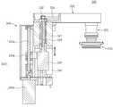
도 6은 도 5에 도시된 수직암부와 가압부를 나타낸 종단면도이고, 도 7은 도 6의 절단선 I-I'에 따른 횡단면도이다.6 is a vertical cross-sectional view showing the vertical arm portion and the pressing portion shown in Figure 5, Figure 7 is a cross-sectional view along the cutting line I-I 'of FIG.
도 2, 도 5 및 도 6을 참조하면, 상기 수직암부(320)는 상기 구동부(340)로부터 제공된 회전력에 의해 회전하여 상기 가압부(310)를 회전시키고, 상기 가압부(310)가 상기 웨이퍼(70)를 가압하는 압력을 제어하기 위한 공기를 상기 가압부(310)에 제공한다.2, 5 and 6, the
구체적으로, 상기 수직암부(320)는 하우징(321), 회전축(322), 로터리 조인트(323), 제1 및 제2 베어링(324a, 324b), 제1 및 제2 보조축(325a, 325b), 자석(326), 및 자성 유체(magnetic fluid)(327)를 포함할 수 있다.In detail, the
상기 하우징(321)은 대체로 원통형의 관 형상을 갖는다. 이 실시예에 있어서, 상기 하우징(321)은 상기 가압부(310)와 인접한 하면(321a) 및 상기 하면(321a)의 단부로부터 위로 연장되어 링 형상을 갖는 측벽(321b)을 구비한다. 상기 하우징(321)의 하면(321a)에는 상기 회전축(322)이 관통하여 삽입되는 관통홀이 형성된다. 상기 하우징(321)의 상단부는 상기 스윙암부(330)의 회전 케이스(331) 안에 삽입되어 상기 회전 케이스(331)에 고정 결합된다.The
상기 회전축(322)은 상기 하우징(321) 내에 설치되고, 상기 하우징(321)과 이격되어 위치한다. 상기 회전축(322)은 대체로 원 기둥 형상을 갖고, 하단부가 상기 하우징(321)의 하면(321a)에 형성된 관통홀을 관통하여 상기 가압부(310)에 고정 결합된다.The
상기 회전축(322)은 상기 하우징(321)의 길이 방향으로 연장되며, 중앙부에 상기 회전축(322)의 길이 방향으로 연장된 공기 통로(322a)가 형성된다. 상기 회전축(322)은 상기 종동 풀리(333)에 연결되어 상기 종동 풀리(333)의 회전력에 의해 길이 방향의 중심축을 기준으로 회전한다. 상기 회전축(322)의 회전시, 상기 하우징(321)은 고정된 상태에서 상기 회전축(322)만 회전한다. 즉, 상기 하우징(321)은 일종의 고정축 기능을 한다.The
상기 회전축(322)의 상단부는 상기 로터리 조인트(323)에 연결 결합되고, 상기 로터리 조인트(323)는 상기 회전축(322)의 공기 통로(322a)에 공기를 제공한다. 상기 종동 풀리(333)에 고정 결합된다. 상기 로터리 조인트(323)는 회전부와 고정부로 이루어지고, 상기 회전부는 상기 종동 풀리(333)에 고정 결합되어 상기 종동 풀리(333)의 회전력에 의해 회전한다. 상기 로터리 조인트(323)의 고정부는 공기를 제공하는 에어 라인(80)에 연결된다. 상기 에어 라인(80)으로부터 제공된 공기는 상기 로터리 조인트(323)를 통해 상기 공기 통로(322a)에 유입되고, 상기 공기 통로(322a)를 따라 흘러 상기 가압부(310)에 유입된다. The upper end of the
상기 하우징(321)과 상기 회전축(322)과의 사이에는 상기 제1 및 제2 베어링(324a, 324b)이 설치된다. 상기 제1 및 제2 베어링(324a. 324b)은 상기 하우징(321)과 상기 회전축(322)을 연결 결합하고, 상기 하우징(321)이 고정된 상태에 서 상기 회전축(322)이 안정적으로 회전하도록 상기 회전축(322)의 위치를 고정시킨다. 상기 제1 베어링(323a)은 상기 스윙암부(330)와 인접하게 위치하고, 상기 제2 베어링(323b)은 상기 가압부(310)와 인접하게 위치한다. 상기 제1 및 제2 베어링(323a, 323b)의 내륜들은 상기 회전축(322)에 끼워져 상기 회전축(322)과 함께 회전하고, 외륜들은 상기 하우징(321)에 결합되어 상기 회전축(322) 회전 시 회전하지 않는다. 따라서, 상기 회전축(322)만 회전하고, 상기 하우징(321)은 회전하지 않는다.The first and
또한, 상기 회전축(322)과 상기 하우징(321)과의 사이에는 상기 제1 및 제2 보조축(325a, 325b)이 더 설치될 수 있다. 상기 제1 및 제2 보조축(325a, 325b)은 상기 제1 및 제2 베어링(324a, 324b) 사이에 설치되고, 상기 하우징(321)의 측벽(321b)과 상기 회전축(322) 사이에 구비된다. 상기 제1 보조축(325a)은 상기 하우징(321) 내벽을 둘러싸고, 상기 하우징(321)을 보호한다. 상기 제2 보조축(325b)은 상기 회전축(322)의 외벽을 둘러싸고, 상기 회전축(322)을 보호한다.In addition, the first and second
도 6 및 도 7을 참조하면, 상기 제2 베어링(324b)의 아래에는 상기 자석(326)이 구비된다. 상기 자석(326)은 상기 하우징(321) 내에서 상기 하우징(321)의 측벽(321b)과 상기 회전축(322) 사이에 개재되고, 상기 하우징(321)의 하면(321a)에 구비되며, 상기 자석(326)은 상기 회전축(322)을 둘러싸는 링 형상을 갖는다. 이 실시예에 있어서, 상기 자석(326)은 상기 하우징(321)의 하면(321a)에 안착된 바닥면, 및 상기 바닥면의 단부로부터 수직하게 연장되어 링 형상을 갖는 측면을 구비한다. 상기 자석(326)의 바닥면에는 상기 회전축(322)이 관통하여 삽입 되는 홀이 형성된다. 또한, 이 실시예에 있어서, 상기 자석(326)은 영구 자석으로 이루어진다.6 and 7, the
상기 자석(326)과 상기 회전축(322)과의 사이에는 상기 자성 유체(327)가 주입된다. 상기 자성 유체(327)는 상기 하우징(321) 내에 구비되고, 상기 하우징(321)의 하면과 접한다. 여기서, 상기 하우징(321)의 하면(321a)과 상기 회전축(322) 간의 이격 거리는 상기 하우징(321)의 측벽(321b)과 상기 회전축(322) 간의 이격 거리 보다 좁다.The
상기 자성 유체(327)는 상기 상기 회전축(322)을 둘러싸며, 상기 자석(326)의 자력에 의해 상기 자석(326)과 상기 회전축(322) 사이에 고정된다. 상기 자성 유체(327)는 상기 회전축(322)의 외주면에 형성된 단턱(322b)과 상기 하우징(321)의 하면 및 상기 자석(236)에 의해 정의된 공간 안에 구비되어 상기 자석(236)과 상기 회전축(322) 사이의 공간을 밀폐한다. 여기서, 상기 단턱(322b)은 상기 하우징(321)의 하면(321a)과 인접하게 위치하며, 상기 자성 유체(327)는 상기 하우징(321)의 하면(321a)에 형성된 관통홀의 바로 위에 위치한다. 이에 따라, 상기 자성 유체(327)는 상기 관통홀을 통해 외부로 노출된다.The
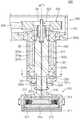
도 8은 수직암부 내에서 발생된 이물이 자석과 자성 유체 측으로 가이드되는 과정을 나타낸 횡단면도이다.8 is a cross-sectional view illustrating a process in which foreign materials generated in the vertical arm part are guided to the magnet and the magnetic fluid.
도 8을 참조하면, 상기 자성 유체(327)는 상기 자석(326)과 상기 회전축(322) 사이의 공간을 밀폐하므로, 상기 하우징(321) 내에 발생된 이물(PC), 예컨대, 상기 제1 및 제2 베어링(324a, 324b)의 작동에 의해 발생된 이물(PC)이 상기 하우징(321) 하면(321a)에 형성된 홀을 통해 외부로 유출되는 것을 방지한다.Referring to FIG. 8, since the
즉, 상기 회전축(321)의 회전 동작에 의해 상기 하우징(321) 안의 공간(DS)에서 발생되는 이물은 주로 자성에 반응하는 금속 물질이 많다. 이러한 이물(PC)은 상기 자석(326)과 상기 자성 유체(327)의 자력에 의해 상기 자석(326)과 상기 자성 유체(327) 측으로 유도된다. 도 8에서 도면 부호 PF는 상기 이물(PC)이 상기 자석(326)과 상기 자성 유체(327) 측으로 유도되는 흐름을 나타낸다.That is, the foreign matter generated in the space DS in the
상기 자석(326)과 상기 자성 유체(327) 측으로 유도된 이물(PC)은 상기 자석(326)에 달라 붙거나 상기 자성 유체(327) 내로 유입된다. 이에 따라, 상기 이물(PC)이 상기 하우징(321)과 상기 회전축(322) 사이의 틈새를 통해 외부로 유출되지 못하므로, 상기 연마 유닛(300)은 상기 수직암부(320) 내에서 발생된 이물(PC)이 연마 공정 중인 웨이퍼로 떨어지는 것을 방지하고, 제품의 수율을 향상시킬 수 있다.The foreign material PC guided to the
한편, 상기 수직암부(320)는 상기 수직암부(320) 내에서 발생된 이물(PC)이 외부로 유출되는 것을 2차적으로 방지하는 이물 방지링(328)을 더 포함할 수 있다. 상기 이물 방지링(328)는 상기 하우징(321)과 상기 가압부(310) 사이에 설치되고, 상기 회전축(322)을 둘러싼다. 상기 이물 방지링(328)은 링 형상을 갖고, 상기 이물 방지링(328)은 상기 회전축(322)에 끼워져 상기 회전축(322)에 밀착 고정되며, 상기 하우징(321)의 하면(321a)에 형성된 홀을 정의하는 면과 상기 회전축(322) 간의 이격 거리 보다 더 넓은 폭을 갖는다. 이에 따라, 상기 하우징(321)과 상기 회전축(322) 사이의 틈새를 통해 이물이 유출되더라도 상기 이물 방지링(328)에 의해 2차적으로 차단된다. 본 발명의 일례로, 상기 이물 방지링(328)은 탄성을 갖는 수지 재질로 이루어지며, 상기 회전축(322)과 함께 회전한다.On the other hand, the
또한, 상기 이물 방지링(328)은 상기 하우징(321)의 하면(321a)과 결합하는 결합 돌기(328a)를 더 포함할 수 있다. 상기 결합 돌기(328a)는 상기 이물 방지링(328)의 상면으로부터 돌출되어 상기 하우징(321)의 하면(321a)에 형성된 결합홈(321c)에 삽입된다.In addition, the foreign
한편, 상기 회전축(322)의 하단부에는 상기 가압부(310)가 고정 설치된다. 상기 가압부(310)는 연마 패드(311), 연마 케이스(312), 상부 및 하부 플레이트(313, 314), 패드 홀더(315), 결합 플레이트(316), 및 벨로우즈(317)를 포함할 수 있다.On the other hand, the
상기 연마 패드(311)는 플레이트 형상을 갖고, 대체로 원형의 링 형상을 갖는다. 상기 연마 패드(311)는 연마 공정 시 하면을 웨이퍼의 상면에 접촉시킨 상태에서 회전하여 웨이퍼를 연마한다. 상기 연마 패드(311)는 상기 웨이퍼의 지름 보다 작은 지름을 갖고, 연마 공정 시 상기 구동부(340)에 의해 스윙하면서 상기 웨이퍼를 연마한다. 이와 같이, 상기 연마 패드(311)가 상기 웨이퍼보다 작은 크기를 가지므로, 상기 연마 유닛(300)은 상기 웨이퍼를 국부적으로 연마할 수 있고, 특정 영역에서의 과연마를 방지할 수 있다.The
상기 연마 패드(311)의 상부에는 상기 연마 케이스(312)가 구비된다. 상기 연마 본체(312)는 대체로 원형의 링 형상을 갖고, 내부에는 상기 상부 및 하부 플레이트(313, 314)와 상기 벨로우즈(317)가 설치된다. 상기 연마 본체(312)의 상면 중앙부에는 결합홀이 형성되고, 상기 결합홀에는 결합 플레이트(316)가 구비된다. 상기 결합 플레이트(316)는 상기 연마 본체(312)와 이격되어 위치하며, 상기 수직암부(320)의 회전축(322)에 고정 결합된다.The polishing
상기 결합 플레이트(316)의 하면에는 상기 상부 플레이트(313)가 고정 설치되고, 상기 상부 플레이트(313)의 아래에는 상기 상부 플레이트(313)와 이격되어 상기 하부 플레이트(314)가 설치된다. 상기 하부 플레이트(314)의 하면에는 상기 패드 홀더(315)가 결합되며, 상기 패드 홀더(315)의 하면에는 상기 연마 패드(311)가 결합된다.The
한편, 상기 상부 플레이트(313)와 상기 하부 플레이트(314) 사이에는 상기 벨로우즈(317)가 구비된다. 상기 벨로우즈(317)는 금속 재질로 이루어지고, 상기 회전축(322)의 공기 통로(322a)로부터 제공되는 공기를 주입받으며, 공기압에 의해 수직 방향으로 팽창 및 수축한다. 연마 공정의 진행시, 상기 벨로우즈(317)는 공기압에 의해 연마 패드(311)가 웨이퍼에 밀착되도록 신장된다. 또한, 상기 기판 지지부재(100)(도 2 참조)의 상부에서 대기 시, 상기 벨로우즈(316)는 상기 공기 통로(322a)로부터 제공되는 진공압에 의해 수축되고, 이에 따라, 상기 연마 패드(311)가 상기 기판 지지부재(100)에 안착된 웨이퍼로부터 이격된다.Meanwhile, the
이와 같이, 상기 가압부(310)는 공기압에 의해 신장 및 수축되는 상기 벨로우즈(317)를 이용하므로, 연마 공정 시 상기 연마 패드(311)는 상기 웨이퍼의 상면 형상에 따라 틸팅이 가능하다.As such, since the
다시, 도 1 내지 도 3을 참조하면, 상기 용기 유닛(200)의 외측에는 상기 제 1 및 제2 처리 유체 공급 유닛(410, 420)이 설치된다. 상기 제1 및 제2 처리 유체 공급 유닛(410, 420)은 상기 웨이퍼(70)의 연마 공정 및 세정 공정에 필요한 처리 유체를 상기 기판 지지유닛(100)에 고정된 웨이퍼(70)에 분사한다. 구체적으로, 상기 제1 처리 유체 공급 유닛(410)은 상기 제2 처리 용기(220)의 측벽(221)에 고정 설치된다. 연마 공정 또는 세정 공정 시, 상기 제1 처리 유체 공급 유닛(410)은 상기 스핀 헤드(110)에 고정된 웨이퍼(70)에 처리 유체를 분사하여 상기 웨이퍼(70)를 처리한다. 이 실시예에 있어서, 상기 제1 처리 유체 공급 유닛(420)에서 분사되는 처리 유체는 웨이퍼(70)의 세정 또는 건조를 위한 처리액일 수도 있고, 건조를 위한 건조 가스일 수도 있다.Again, referring to FIGS. 1 to 3, the first and second processing
본 발명의 일례로, 상기 제1 처리 유체 공급 유닛(410)은 네 개의 분사 노즐을 구비하나, 상기 분사 노즐의 개수는 웨이퍼(70) 세정에 사용되는 상기 처리 유체의 종류수에 따라 증가하거나 감소할 수도 있다.In one example of the present invention, the first processing
상기 제2 처리 유체 공급 유닛(420)은 스윙 가능하게 설치되고, 상기 스핀 헤드(110)에 고정된 웨이퍼(70)의 상면에 처리 유체를 분사한다. 상기 제2 처리 유체 공급 유닛(420)에서 제공되는 처리 유체는 슬러리일 수도 있다. 또한, 상기 연마 공정시, 슬러리는 상기 제2 처리 유체 공급 유닛(420)이 아닌 별도의 약액 분사 부재(미도시)에 의해 상기 웨이퍼(70)에 분사될 수도 있다.The second processing
한편, 상기 브러쉬 유닛(510)은 연마 공정 후 웨이퍼(70) 표면의 이물을 물리적으로 제거한다. 상기 브러쉬 유닛(510)은 상기 웨이퍼(70)에 표면에 접촉되어 상기 웨이퍼(70) 표면의 이물을 물리적으로 닦아 내는 브러쉬 패드를 구비하고, 스 윙이 가능하다. 세정 공정시, 상기 브러쉬 유닛(510)은 스윙 동작을 통해 상기 브러쉬 패드를 상기 스핀 헤드(110)의 상부에 배치시킨 상태에서 상기 브러쉬 패드를 회전시켜 상기 스핀 헤드(110)에 고정된 웨이퍼(70)를 세정한다.On the other hand, the
상기 브러쉬 유닛(510)의 일측에는 상기 에어로졸 유닛(520)이 배치된다. 상기 에어로졸 유닛(520)은 상기 스핀 헤드(110)에 고정된 웨이퍼(70)에 처리액을 미세 입자형태로 고압 분무하여 상기 웨이퍼(70) 표면의 이물을 제거한다. 본 발명의 일례로, 상기 에어로졸 유닛(520)은 초음파를 이용하여 상기 처리액을 작은 입자 형태로 분무한다. 상기 브러쉬 유닛(510)은 비교적 큰 입자의 이물을 제거하는 데 사용되며, 상기 에어로졸 유닛(520)은 상기 브러쉬 유닛(510)에 비해 비교적으로 작은 입자의 이물을 제거하는 데 사용된다.The
한편, 상기 패드 컨디셔닝 유닛(600)은 상기 연마 유닛(300)이 홈 포트(home port)에서 대기 중일 때, 상기 연마 유닛(300)을 세정 및 재생시킨다. 즉, 상기 연마 패드(311)(도 6 참조)에는 상기 연마 공정의 효율을 향상시키기 위해 상기 웨이퍼와 접촉되는 면에 소정의 연마 패턴이 형성된다. 이러한 연마 패턴은 상기 웨이퍼를 연마하는 과정에서 상기 웨이퍼와의 마찰에 의해 점점 마모되며, 연마 과정에서 사용되는 약액들이 상기 연마 패턴 내에서 경화될 수도 있다. 상기 패드 컨디셔닝 유닛(600)은 연마 패드(311)의 표면을 연마하여 상기 연마 패드(311)를 재생시킨다.Meanwhile, the
이상 실시예를 참조하여 설명하였지만, 해당 기술 분야의 숙련된 당업자는 하기의 특허 청구의 범위에 기재된 본 발명의 사상 및 영역으로부터 벗어나지 않는 범위 내에서 본 발명을 다양하게 수정 및 변경시킬 수 있음을 이해할 수 있을 것이다.Although described with reference to the embodiments above, those skilled in the art will understand that the present invention can be variously modified and changed without departing from the spirit and scope of the invention as set forth in the claims below. Could be.
도 1은 본 발명의 일 실시예에 따른 매엽식 연마 시스템을 개략적으로 나타낸 도면이다.1 is a view schematically showing a sheet type polishing system according to an embodiment of the present invention.
도 2는 도 1에 도시된 기판 연마 장치를 나타낸 사시도이다.FIG. 2 is a perspective view illustrating the substrate polishing apparatus shown in FIG. 1.
도 3은 도 2에 도시된 기판 지지유닛 및 용기 유닛을 구체적으로 나타낸 부분 절개 사시도이다.3 is a partial cutaway perspective view illustrating the substrate support unit and the container unit shown in FIG. 2 in detail.
도 4는 도 2에 도시된 연마 유닛을 나타낸 사시도이다.4 is a perspective view illustrating the polishing unit illustrated in FIG. 2.
도 5는 도 4에 도시된 연마 유닛을 나타낸 부분 절개 측면도이다.FIG. 5 is a partial cutaway side view of the polishing unit shown in FIG. 4. FIG.
도 6은 도 5에 도시된 수직암부와 가압부를 나타낸 종단면도이다.6 is a vertical cross-sectional view showing the vertical arm portion and the pressing portion shown in FIG.
도 7은 도 6의 절단선 I-I'에 따른 횡단면도이다.FIG. 7 is a cross-sectional view taken along the line II ′ of FIG. 6.
도 8은 수직암부 내에서 발생된 이물이 자석과 자성 유체 측으로 가이드되는 과정을 나타낸 횡단면도이다.8 is a cross-sectional view illustrating a process in which foreign materials generated in the vertical arm part are guided to the magnet and the magnetic fluid.
* 도면의 주요 부분에 대한 부호 설명 *Description of the Related Art [0002]
100 : 기판 지지부재200 : 용기 유닛100
300 : 연마 유닛410 : 제1 처리액 공급 유닛300: polishing unit 410: first processing liquid supply unit
420 : 제2 처리액 공급 유닛510 : 브러쉬 유닛420: second processing liquid supply unit 510: brush unit
520 : 에어로졸 유닛600 : 패드 컨디셔닝 유닛520: aerosol unit 600: pad conditioning unit
1000 : 기판 연마부1000: substrate polishing part
Claims (12)
Translated fromKoreanPriority Applications (1)
| Application Number | Priority Date | Filing Date | Title |
|---|---|---|---|
| KR1020090073476AKR101042323B1 (en) | 2009-08-10 | 2009-08-10 | Polishing unit and substrate polishing apparatus having the same |
Applications Claiming Priority (1)
| Application Number | Priority Date | Filing Date | Title |
|---|---|---|---|
| KR1020090073476AKR101042323B1 (en) | 2009-08-10 | 2009-08-10 | Polishing unit and substrate polishing apparatus having the same |
Publications (2)
| Publication Number | Publication Date |
|---|---|
| KR20110015993A KR20110015993A (en) | 2011-02-17 |
| KR101042323B1true KR101042323B1 (en) | 2011-06-17 |
Family
ID=43774495
Family Applications (1)
| Application Number | Title | Priority Date | Filing Date |
|---|---|---|---|
| KR1020090073476AActiveKR101042323B1 (en) | 2009-08-10 | 2009-08-10 | Polishing unit and substrate polishing apparatus having the same |
Country Status (1)
| Country | Link |
|---|---|
| KR (1) | KR101042323B1 (en) |
Families Citing this family (1)
| Publication number | Priority date | Publication date | Assignee | Title |
|---|---|---|---|---|
| KR101951186B1 (en)* | 2017-11-07 | 2019-02-25 | 한국생산기술연구원 | Conditioner of chemical mechanical polishing apparatus for uniform-wearing of polishing pad |
Citations (3)
| Publication number | Priority date | Publication date | Assignee | Title |
|---|---|---|---|---|
| JPH10109264A (en) | 1996-10-02 | 1998-04-28 | Ebara Corp | Polishing device |
| JP2004319730A (en) | 2003-04-16 | 2004-11-11 | Nikon Corp | Processing apparatus, semiconductor device manufacturing method using the same, and semiconductor device manufactured by the method |
| KR20090024328A (en)* | 2007-09-04 | 2009-03-09 | 삼성전자주식회사 | Wafer Polishing Carrier Device and Chemical Mechanical Grinding Equipment |
- 2009
- 2009-08-10KRKR1020090073476Apatent/KR101042323B1/enactiveActive
Patent Citations (3)
| Publication number | Priority date | Publication date | Assignee | Title |
|---|---|---|---|---|
| JPH10109264A (en) | 1996-10-02 | 1998-04-28 | Ebara Corp | Polishing device |
| JP2004319730A (en) | 2003-04-16 | 2004-11-11 | Nikon Corp | Processing apparatus, semiconductor device manufacturing method using the same, and semiconductor device manufactured by the method |
| KR20090024328A (en)* | 2007-09-04 | 2009-03-09 | 삼성전자주식회사 | Wafer Polishing Carrier Device and Chemical Mechanical Grinding Equipment |
Also Published As
| Publication number | Publication date |
|---|---|
| KR20110015993A (en) | 2011-02-17 |
Similar Documents
| Publication | Publication Date | Title |
|---|---|---|
| KR101170760B1 (en) | Substrate polishing apparatus | |
| KR101004435B1 (en) | Substrate Polishing Apparatus and Substrate Polishing Method Using The Same | |
| KR101037634B1 (en) | Substrate Polishing Apparatus and Substrate Cleaning Method Using the Same | |
| KR101042321B1 (en) | Substrate Polishing Apparatus and Method | |
| KR101042323B1 (en) | Polishing unit and substrate polishing apparatus having the same | |
| KR101098365B1 (en) | Apparatus and method of treating substrate | |
| KR101041451B1 (en) | Substrate support member, substrate polishing apparatus having same, and substrate polishing method using same | |
| KR101041452B1 (en) | Substrate supporting member, substrate polishing apparatus having the same and method of polishing substrate using the same | |
| KR101034235B1 (en) | Substrate Polishing Apparatus and Substrate Polishing Method Using The Same | |
| KR101098368B1 (en) | Substrate polishing apparatus and method of polishing substrate using the same | |
| KR101095039B1 (en) | Substrate Polishing Apparatus and Method | |
| KR101086786B1 (en) | Substrate support unit, and substrate polishing apparatus having same | |
| KR101083778B1 (en) | Pad conditioning unit, substrate polishing apparatus having same, and polishing pad regeneration method using same | |
| KR101191036B1 (en) | Substrate Processing Apparatus and Method | |
| KR101024357B1 (en) | Fluid supply unit, substrate processing apparatus having same, and substrate processing method using same | |
| KR101009046B1 (en) | Substrate Polishing Apparatus and Substrate Polishing Method Using The Same | |
| KR101042319B1 (en) | Substrate polishing apparatus | |
| KR101041873B1 (en) | Substrate Polishing Apparatus and Substrate Polishing Method Using The Same | |
| KR101160165B1 (en) | Substrate polishing apparatus | |
| KR101080867B1 (en) | Substrate polishing apparatus and method of polishing substrate using the same | |
| KR101041874B1 (en) | Polishing unit, substrate polishing apparatus having same, and substrate polishing method using same | |
| KR101069848B1 (en) | Substrate supporting member, substrate polishing apparatus having the same and method of polishing substrate using the same | |
| KR101041453B1 (en) | Pad conditioning unit, substrate polishing apparatus having same, and polishing pad regeneration method using same | |
| KR101034237B1 (en) | Polishing unit, substrate polishing apparatus having same, and substrate polishing method using same | |
| KR20110055500A (en) | Substrate polishing apparatus |
Legal Events
| Date | Code | Title | Description |
|---|---|---|---|
| A201 | Request for examination | ||
| PA0109 | Patent application | Patent event code:PA01091R01D Comment text:Patent Application Patent event date:20090810 | |
| PA0201 | Request for examination | ||
| E902 | Notification of reason for refusal | ||
| PE0902 | Notice of grounds for rejection | Comment text:Notification of reason for refusal Patent event date:20110217 Patent event code:PE09021S01D | |
| PG1501 | Laying open of application | ||
| E701 | Decision to grant or registration of patent right | ||
| PE0701 | Decision of registration | Patent event code:PE07011S01D Comment text:Decision to Grant Registration Patent event date:20110531 | |
| GRNT | Written decision to grant | ||
| PR0701 | Registration of establishment | Comment text:Registration of Establishment Patent event date:20110610 Patent event code:PR07011E01D | |
| PR1002 | Payment of registration fee | Payment date:20110613 End annual number:3 Start annual number:1 | |
| PG1601 | Publication of registration | ||
| FPAY | Annual fee payment | Payment date:20140610 Year of fee payment:4 | |
| PR1001 | Payment of annual fee | Payment date:20140610 Start annual number:4 End annual number:4 | |
| FPAY | Annual fee payment | Payment date:20150611 Year of fee payment:5 | |
| PR1001 | Payment of annual fee | Payment date:20150611 Start annual number:5 End annual number:5 | |
| FPAY | Annual fee payment | Payment date:20170613 Year of fee payment:7 | |
| PR1001 | Payment of annual fee | Payment date:20170613 Start annual number:7 End annual number:7 | |
| PR1001 | Payment of annual fee | Payment date:20200603 Start annual number:10 End annual number:10 | |
| PR1001 | Payment of annual fee | Payment date:20210325 Start annual number:11 End annual number:11 | |
| PR1001 | Payment of annual fee | Payment date:20220525 Start annual number:12 End annual number:12 | |
| PR1001 | Payment of annual fee | Payment date:20230524 Start annual number:13 End annual number:13 |