KR101040732B1 - Transmission line monitoring device - Google Patents
Transmission line monitoring deviceDownload PDFInfo
- Publication number
- KR101040732B1 KR101040732B1KR1020100119291AKR20100119291AKR101040732B1KR 101040732 B1KR101040732 B1KR 101040732B1KR 1020100119291 AKR1020100119291 AKR 1020100119291AKR 20100119291 AKR20100119291 AKR 20100119291AKR 101040732 B1KR101040732 B1KR 101040732B1
- Authority
- KR
- South Korea
- Prior art keywords
- power
- transmission
- monitoring
- voltage
- line
- Prior art date
- Legal status (The legal status is an assumption and is not a legal conclusion. Google has not performed a legal analysis and makes no representation as to the accuracy of the status listed.)
- Active
Links
Images


Classifications
- G—PHYSICS
- G08—SIGNALLING
- G08B—SIGNALLING OR CALLING SYSTEMS; ORDER TELEGRAPHS; ALARM SYSTEMS
- G08B25/00—Alarm systems in which the location of the alarm condition is signalled to a central station, e.g. fire or police telegraphic systems
- G08B25/01—Alarm systems in which the location of the alarm condition is signalled to a central station, e.g. fire or police telegraphic systems characterised by the transmission medium
- G08B25/08—Alarm systems in which the location of the alarm condition is signalled to a central station, e.g. fire or police telegraphic systems characterised by the transmission medium using communication transmission lines
- G—PHYSICS
- G01—MEASURING; TESTING
- G01R—MEASURING ELECTRIC VARIABLES; MEASURING MAGNETIC VARIABLES
- G01R31/00—Arrangements for testing electric properties; Arrangements for locating electric faults; Arrangements for electrical testing characterised by what is being tested not provided for elsewhere
- G01R31/08—Locating faults in cables, transmission lines, or networks
- G—PHYSICS
- G08—SIGNALLING
- G08B—SIGNALLING OR CALLING SYSTEMS; ORDER TELEGRAPHS; ALARM SYSTEMS
- G08B23/00—Alarms responsive to unspecified undesired or abnormal conditions
- H—ELECTRICITY
- H02—GENERATION; CONVERSION OR DISTRIBUTION OF ELECTRIC POWER
- H02H—EMERGENCY PROTECTIVE CIRCUIT ARRANGEMENTS
- H02H7/00—Emergency protective circuit arrangements specially adapted for specific types of electric machines or apparatus or for sectionalised protection of cable or line systems, and effecting automatic switching in the event of an undesired change from normal working conditions
- H02H7/26—Sectionalised protection of cable or line systems, e.g. for disconnecting a section on which a short-circuit, earth fault, or arc discharge has occured
Landscapes
- Physics & Mathematics (AREA)
- General Physics & Mathematics (AREA)
- Business, Economics & Management (AREA)
- Emergency Management (AREA)
- Remote Monitoring And Control Of Power-Distribution Networks (AREA)
Abstract
Translated fromKorean
Description
Translated fromKorean본 발명은 송배전 시스템에 관한 것으로, 더욱 상세하게는 송배전 시스템의 가공선로 또는 지중선로에 권취되어 송배전선로의 물리적 형상변화 및 전력 상태를 감시하고, 감시결과를 무선 네트워크로 탑재하기 위한 송배전선로 감시장치에 관한 것이다.The present invention relates to a transmission and distribution system, and more particularly, the transmission and distribution line monitoring apparatus for monitoring the physical shape change and power state of the transmission and distribution line is wound on the overhead line or underground line of the transmission and distribution system, and to mount the monitoring result to the wireless network It is about.
최근 들어, 송배전선으로는 대용량 송전을 위한 증용량전선(HCC), 가공지선으로는 광섬유를 포함하여 통신기능을 추가한 광섬유 복합 가공지선(OPGW)의 사용이 증가하고 있다. 이러한, 발전소로부터 발전된 전력을 가공선을 통해 수용지로 공급하는데 있어서 가공선의 사고 발생, 즉 주위환경으로 인한 가공선 훼손 등에 의해 발생되는 그 파급 효과는 대단히 크기 때문에 가공선을 감시하는 기술은 가공선 선로 관리에 있어서 중요한 부분을 차지한다.In recent years, the use of an optical fiber composite overhead line (OPGW) with added communication functions, including an optical fiber as an overhead line (HCC) for a large capacity transmission, and an optical fiber as a overhead line has been increasing. In the supply of electric power generated from the power plant to the receiving site through the overhead line, the ripple effect caused by the accident of the overhead line, that is, the damage of the overhead line due to the surrounding environment, is so great that the technology for monitoring the overhead line is important for the overhead line management. Take part.
그러나, 가공선은 비교적 산악지역이나 호수 등 상주 인력을 배치하기 어려운 지역에 설치되며, 가공선의 선로가 길기 때문에 인력에 의한 가공선의 감시가 용이하지 못한 단점이 있다. 따라서, 가공선을 안전하게 유지하여 수용지로의 지속적인 전력공급을 가능하게 하고 유사시에는 즉각적인 검출과 차단으로 사고를 방지하고 복구를 조기에 매듭짓기 위하여 여러 감시장비와 제어장비 및 인력의 필요성이 중요시되고 있다.However, the overhead line is installed in an area where it is difficult to place resident manpower such as a mountainous area or a lake, and there is a disadvantage in that the overhead line of the overhead line is not easy to monitor the overhead line by manpower. Therefore, the necessity of various monitoring equipment, control equipment, and manpower is important in order to keep the overhead line safe to enable continuous power supply to the receiving area, and in case of emergency, to prevent accidents by early detection and interruption and to knot recovery early.
이에, 가공선 감시의 중요성에 따라 여러 센서와 영상 장비를 구비하고 있는 가공선 감시용 장치를 포함하여 이루어진 가공선 감시시스템을 개발하게 되었다. 이러한, 가공선 감시시스템은 가공선에 센서를 장착하거나 철탑에 카메라를 장착하여 가공선 및 그 주위 환경을 감시하며, 해당 가공선 및 그 주위 환경에 대한 정보를 관리자에게 제공해 주는 기능을 수행하도록 구현되고 있는 실정이다.Accordingly, according to the importance of overhead line monitoring, a overhead line monitoring system including a overhead line monitoring device equipped with various sensors and imaging equipment has been developed. The overhead line monitoring system is equipped with a sensor on the overhead line or a camera mounted on a steel tower to monitor the overhead line and its surroundings, and to provide information to the manager about the overhead line and its surroundings. .
예를 들어, 기존의 가공선 감시 장치는 철탑에 장착되어 있는 폐쇄회로 카메라를 이용하여 가공선 및 애자 연결 부위의 이미지를 촬영하여 해당 촬영된 이미지를 가공선을 이루는 광섬유 복합 가공지선(OPGW), 또는 무선통신 모듈을 통해 감시시스템 서버로 전송하도록 구현되어 있다. 이에, 관리자는 해당 가공선 및 애자 연결부위의 이미지를 감시시스템 서버를 통해 모니터링 하게 된다. 또한, 가공선 설비의 고장에 주원인으로 작용하는 기후 및 환경의 변화를 감시하기 위해 해당하는 센서를 가공선에 장착하여 해당 가공선 주위의 풍향, 풍속, 가공선 온도 및 가공선에 흐르는 전력의 변화에 대한 정보를 검출하고 해당 검출된 정보를 감시시스템 서버로 전송하여 이를 관리자가 모니터링 할 수 있도록 구현되어 있다.For example, the conventional overhead line monitoring device uses a closed circuit camera mounted on a steel tower to take images of overhead lines and insulator joints, and uses the optical fiber composite overhead line (OPGW), or wireless communication, to form the overhead line. It is implemented to transmit to the surveillance system server through the module. Thus, the manager monitors the image of the overhead line and insulator connection through the surveillance system server. In addition, in order to monitor changes in the climate and environment that are the main causes of breakdowns in overhead line equipment, a corresponding sensor is mounted on the overhead line to detect information on the wind direction, wind speed, overhead line temperature and changes in power flowing through the overhead line. The system transmits the detected information to the surveillance system server so that the administrator can monitor it.
그러나, 기존의 가공선 감시 장치에서의 가공선 감시용 장치는 센서나 카메라가 가공선이나 철탑에 고정 장착되어 있기 때문에, 가공선 부식 등의 가공선 훼손 상태 및 가공선 주변의 유해 환경(예를 들어, 수목이 자라는 현상 등)을 세밀하게 관찰하기가 어려운 문제점이 있었다.
However, in the conventional overhead line monitoring device, since the overhead line monitoring device has a sensor or camera fixedly mounted on the overhead line or steel tower, the damaged state of the overhead line such as corrosion of the overhead line and the harmful environment around the overhead line (for example, the growth of trees) Etc.) was difficult to observe in detail.
본 발명은 이와 같은 문제점을 해결하기 위해 창출된 것으로, 본 발명의 목적은 일체화된 구조를 갖고 임의의 가공선로 또는 지중선로에 영구장착되어 송배전선로의 이상상태를 실시간으로 감시할 수 있도록 함에 따라, 배전설비의 감시 효율을 증대시킬 수 있는 송배전선로 감시 장치를 제공함에 있다.The present invention has been made to solve the above problems, the object of the present invention is to have an integrated structure and permanently mounted on any overhead line or underground line to monitor the abnormal state of the transmission and distribution line in real time, It is to provide a transmission line monitoring device that can increase the monitoring efficiency of the distribution equipment.
본 발명의 다른 목적은, 자연재해로 인한 배선선로의 하중 증가 또는 기준치 이상의 요동상태를 감지하고, 감지결과를 무선송출함으로써 배선선로의 물리적 변화를 감시하여 추후 발생 우려에 대한 요소를 사전에 인지할 수 있는 송배전선로 감시 장치를 제공함에 있다.Another object of the present invention is to detect an increase in load of a wiring line due to a natural disaster or a fluctuation state above a reference value, and to monitor the physical change of the wiring line by wirelessly transmitting the detection result so as to recognize in advance the factors of concern about future occurrence. It is to provide a transmission line monitoring device that can be.
본 발명의 또 다른 목적은, 송배전선로 상으로 권취되는 전류검출 센서로부터 이상전류 및 전압의 변화를 인지함으로써, 송전 또는 배전의 효율적 관리가 가능한 송배전선로 감시 장치를 제공함에 있다.Still another object of the present invention is to provide a transmission line monitoring apparatus capable of efficiently managing transmission or distribution by recognizing changes in abnormal current and voltage from a current detection sensor wound on a transmission line.
본 발명의 또 다른 목적은, 배선선로의 유도 전자기력을 이용하여 소비전력량을 구축하도록 함에 따라, 일 회 설치시 영구적으로 사용 가능한 송배전선로 감시 장치를 제공함에 있다.
Still another object of the present invention is to provide a power transmission line monitoring device that can be used permanently at a time of installation, by using the induced electromagnetic force of the wiring line to build a power consumption.
상기 목적을 달성하기 위한 본 발명의 관점에 따른 송배전선로 감시장치는, 전력 송배전 시스템에서의 송배전선로 상태를 감시하는 장치에 있어서, 소정 형상의 하우징을 갖는 본체 상단에 설치되어 송배전선로에 권취되도록 결합되며 다수의 권취 코일을 포함하는 CT 하우징으로 구성되고; 상기 CT 하우징은 원통형 구조에서 중앙이 절개되어 제1 권취커버 및 제2 권취커버로 분리되며, 절개면의 상단에 회동 힌지가 결합되어 상기 제1 권취커버 및 제2 권취커버가 회동 개폐 가능하도록 성형되며; 상기 본체는 본체의 기울어진 각도를 인지하고, 상기 코일로부터 유도되는 전류, 전압을 검출하여 송전 또는 배전 전력을 인지하기 위한 센싱 기능과, 상기 센싱 기능을 기반으로 전력상태를 감시하는 전력감시 기능과, 상기 코일로부터 유도된 전력을 시스템 전원으로 변환하는 전원 변환 기능을 포함하여, 상기 전력상태를 소정의 통신 네트워크로 탑재하도록 무선 송출기능 및 시스템 운용을 위한 시스템 관리기능을 수행하는 제어장치를 포함하고, 상기 전력감시 기능은, 순시전압저하(Instantaneous voltage sag or dip) 감시모드, 순시전압상승(Instantaneous voltage swell) 감시모드, 순시정전(Instantaneous Interruption) 감시모드, 고조파(Harmonics) 감시모드, 불평형률(Current Unbalance) 감시모드 중 어느 하나 이상을 감시하는 것을 특징으로 한다.Transmission line monitoring apparatus according to an aspect of the present invention for achieving the above object, in the apparatus for monitoring the state of the transmission line in the power transmission and distribution system, is installed on the upper end of the main body having a predetermined shape housing coupled to be wound on the transmission line A CT housing comprising a plurality of winding coils; The CT housing is cut in the center of the cylindrical structure and separated into a first winding cover and a second winding cover, and a pivoting hinge is coupled to an upper end of the incision surface to form the first winding cover and the second winding cover to be rotatable open and closed. Become; The main body has a sensing function for recognizing the inclination angle of the main body, the current and voltage derived from the coil to detect the transmission or distribution power, and a power monitoring function for monitoring the power state based on the sensing function; And a control device for performing a wireless transmission function and a system management function for operating the system, including a power conversion function for converting power derived from the coil into system power, to mount the power state to a predetermined communication network. The power monitoring function includes: instantaneous voltage sag or dip monitoring mode, instantaneous voltage swell monitoring mode, instantaneous interrupt monitoring mode, harmonics monitoring mode, and unbalance rate Current Unbalance) characterized in that to monitor any one or more of the monitoring mode.
본 발명의 바람직한 실시 예에 따르면, 상기 제어장치는 상기 제1 CT로부터 검출된 유도전압을 정류 및 평활시켜 소망하는 전압 및 전력으로 변환하여 시스템 전원을 공급하는 전원 변환모듈; 상기 제2 CT로부터 검출된 전류 및 전압 신호를 소정 레벨로 증폭시키는 증폭부; 상기 증폭부의 출력 신호를 디지털 신호로 변환하는 AD 컨버터; 상기 본체의 기울어진 상태 또는 기준치 이상의 진동, 요동 상태를 전기적 신호로 변환 및 신호증폭하는 자이로센서 모듈; 상기 송배전선로의 전력상태를 감시하기 위한 알고리즘, 상기 알고리즘에 근거하여 검출된 전력상태를 데이터화된 정보로 저장 관리하는 메모리; 상기 메모리로 탑재된 전력상태 감시 알고리즘에 근거하여, 상기 AD 컨버터의 출력 데이터에 대한 전력분석을 수행하고, 상기 자이로센서 모듈로부터 인지되는 송배전선로의 물리적 변화를 판단하며, 그 결과를 시각정보와 더불어 상기 메모리로 저장관리되도록 제어하고, 실시간 전력 감시 및 송배전선로의 물리적 변화 감시를 토대로 이벤트 발생 여부를 판단한 후, 기 저장된 데이터를 외부로 송출하는 제어부; 및 상기 제어부의 데이터 송출 지시에 응답하여 기 설정된 통신 네트워크로 해당 데이터를 전송 제어하는 통신모듈로 이루어진 것을 특징으로 한다.
According to a preferred embodiment of the present invention, the control device includes a power conversion module for supplying system power by rectifying and smoothing the induced voltage detected from the first CT to a desired voltage and power; An amplifier for amplifying the current and voltage signals detected from the second CT to a predetermined level; An AD converter for converting the output signal of the amplifier into a digital signal; A gyro sensor module for converting an inclined state or vibration of the main body or a vibration of the main body into an electrical signal and amplifying the signal; An algorithm for monitoring a power state of the transmission and distribution line, and a memory configured to store and manage the power state detected based on the algorithm as dataized information; Based on the power state monitoring algorithm loaded into the memory, power analysis is performed on the output data of the AD converter, and the physical change of the transmission / distribution line recognized from the gyro sensor module is determined, and the result is combined with visual information. A controller for controlling the storage to be stored in the memory, determining whether an event occurs based on real-time power monitoring and physical change monitoring of a transmission and distribution line, and then transmitting previously stored data to the outside; And a communication module configured to control transmission of corresponding data to a preset communication network in response to a data transmission instruction of the controller.
본 발명에서 제시되는 송배전선로 감시장치는, 일체화된 구조를 갖고 임의의 가공선로 또는 지중선로에 영구장착되어 송배전선로의 이상상태를 실시간으로 감시할 수 있도록 함에 따라, 배전설비의 감시 효율을 증대시킬 수 있으며, 자연재해로 인한 배선선로의 하중 증가 또는 기준치 이상의 요동상태를 감지하고, 감지결과를 무선 송출함으로써 배선선로의 물리적 변화를 감시하여 추후 발생 우려에 대한 요소를 사전에 인지할 수 있음에 따라 전력 설비의 효율적 관리를 유도할 수 있는 효과가 있다.
The transmission and distribution line monitoring apparatus proposed in the present invention has an integrated structure and is permanently mounted on an arbitrary overhead line or underground line to monitor the abnormal state of the transmission and distribution line in real time, thereby increasing the monitoring efficiency of the distribution facility. It is possible to detect the increase in load of the wiring line due to natural disaster or fluctuating condition above the standard value, and to monitor the physical change of the wiring line by transmitting the detection result wirelessly, so that the factors for the possibility of future occurrence can be recognized in advance. There is an effect that can lead to efficient management of the power equipment.
도 1은 종래 가공선 감시 시스템을 나타낸 도면이다.
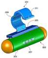
도 2는 본 발명에 따른 송배전선로 감시 장치를 나타낸 사시도이다.
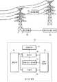
도 3은 도 2의 주요 기능을 설명하기 위한 구성도이다.
도 4는 본 발명의 일부 기능에 따른 동작을 설명하기 위한 도면이다.1 is a view showing a conventional overhead line monitoring system.
2 is a perspective view showing a transmission line monitoring device according to the present invention.
3 is a configuration diagram illustrating the main functions of FIG. 2.
4 is a view for explaining an operation according to some functions of the present invention.
이하, 본 발명의 바람직한 실시 예를 첨부된 예시도면에 의거 상세히 설명하면 다음과 같다.Hereinafter, preferred embodiments of the present invention will be described in detail with reference to the accompanying drawings.
먼저, 도 2는 본 발명에 따른 송배전선로 감시장치를 나타낸 사시도이다. 도시된 바와 같이, 소정 형상의 하우징을 갖는 본체(203) 상단에 설치되어 송배전선로에 권취되도록 결합되는 CT 하우징(201)으로 구성된다. 상기 CT 하우징(201)은 원통형 구조에서 중앙이 절개되어 제1 권취커버(209) 및 제2 권취커버(211)로 분리되고, 절개면의 상단에 회동 힌지가 결합되어 상기 제1 권취커버(209) 및 제2 권취커버(211)가 회동 개폐 가능한 구조로 성형된다. 따라서, 상기 CT 하우징(201)은 송배전선로를 수용함에 있어, 상기 제1 권취커버(209)를 개구시킨 후, 상기 CT 하우징(201)의 중앙으로 송배전선로의 외주부를 수용토록 한다. 이후, 상기 제1 권취커버(209)는 회동시켜 제2 권취커버(211)와 밀착시킨다. 상기 제1 권취커버(209) 및 제2 권취커버(211)는 하단부에 마련된 체결홈(205)에 의해 나사결합된다.First, Figure 2 is a perspective view showing a transmission line monitoring device according to the present invention. As shown, it is composed of a
상기 CT 하우징(201)의 내부에는 공지된 바와 같이 다수의 코일이 권취되어 있으며, 상기 코일은 송배전선로로부터 유도되는 전자기장에 의해 소정의 전력이 야기되도록 한다. 이에, 상기 본체(203)는 본체의 기울어진 각도를 인지하고, 상기 코일로부터 유도되는 전류, 전압을 검출하여 송전 또는 배전 전력을 인지하기 위한 센싱 기능과, 상기 센싱 기능을 기반으로 전력상태를 감시하는 전력감시 기능과, 상기 코일로부터 유도된 전력을 시스템 전원으로 변환하는 전원 변환 기능을 포함하여, 상기 전력상태를 소정의 통신 네트워크로 탑재하도록 무선 송출기능 및 시스템 운용을 위한 시스템 관리기능을 갖는다. 미설명된 동작 표시부(207)는 시스템의 동작 상태를 표시하기 위한 것으로, 이는 제조과정에서 테스트용 램프로 인지됨이 바람직할 것이다.As is known, a plurality of coils are wound inside the
도 3은 본 발명에 따른 주요 기능을 설명하기 위한 구성도이다. 도시된 바와 같이, 상기 CT 하우징(201)에 내설되어 송배전선로의 유도 전자기장으로부터 유도전압을 제공하는 제1 CT와, 상기 송배전선로로 공급되는 전력에 대한 유도 전류, 전압을 제공하는 제2 CT로 구성된 CT와, 상기 제1 CT로부터 검출된 유도전압을 정류 및 평활시켜 소망하는 전압 및 전력으로 변환하여 시스템 전원을 공급하는 전원 변환모듈(307)과, 상기 제2 CT로부터 검출된 전류 및 전압 신호를 소정 레벨로 증폭시키는 증폭부(311)와, 상기 증폭부(311)의 출력 신호를 디지털 신호로 변환하는 AD 컨버터(313)와, 상기 본체(203)의 기울어진 상태 또는 기준치 이상의 진동, 요동 상태를 전기적 신호로 변환 및 신호증폭하는 자이로센서 모듈(305)과, 상기 송배전선로의 전력상태를 감시하기 위한 알고리즘, 상기 알고리즘에 근거하여 검출된 전력상태를 데이터화된 정보로 저장 관리하는 메모리(303), 상기 메모리(303)로 탑재된 전력상태 감시 알고리즘에 근거하여, 상기 AD 컨버터(313)의 출력 데이터에 대한 전력분석을 수행하고, 상기 자이로센서 모듈(305)로부터 인지되는 송배전선로의 물리적 변화를 판단하며, 그 결과를 시각정보와 더불어 상기 메모리(303)로 저장관리되도록 제어하고, 실시간 전력 감시 및 송배전선로의 물리적 변화 감시를 토대로 이벤트 발생 여부를 판단한 후, 기 저장된 데이터를 외부로 송출하는 제어부(301)와, 상기 제어부(301)의 데이터 송출 지시에 응답하여 기 설정된 통신 네트워크로 해당 데이터를 전송 제어하는 통신모듈(315)로 이루어진다.3 is a configuration diagram for explaining the main function according to the present invention. As shown in the drawing, a first CT provided in the
여기서, 상기 자이로센서 모듈(305)은 3축 자이로센서로 구성됨으로써, 상기 송배전선로의 상하 진동 및 좌우 진동에 따른 변화량을 판단한다. 상기 송배전선로의 상하 진동은 폭설 또는 과도한 주변 온도 상승으로 인한 송배전선로가 인장 되는 현상을 의미하며, 상기 송배전선로의 과도 또는 급격한 좌우 진동은 송배전 시스템의 물리적 변화 또는 외력에 의한 강압 상태로 인지될 수 있을 것이다.Here, the
한편, 상기 AD 컨버터(313)로부터 검출되는 전력감시는 먼저, 전압저하(Voltage sag or dip) 즉, 정격주파수에서 지속시간이 0.5싸이클에서 1분정도, 전압저하의 정도가 실효치기준 0.1 p.u. 에서 0.9 p.u. 인 현상을 나타내는 순시전압저하(Instantaneous voltage sag or dip) 감시, 전압상승은 정격주파수에서 지속시간이 0.5싸이클에서 1분정도, 전압크기가 실효치기준 1.1 p.u. 에서 1.8 p.u.정도로 되는 현상으로서, 이 중에서 지속시간이 0.5 싸이클에서 30 싸이클정도까지의 현상을 나타내는 순시전압상승(Instantaneous voltage swell) 감시, 단기간정전(Short-duration Interruption)은 공급전압이나 부하전류가 1분을 초과하지 않는 시간범위내에서 0.1 p.u.미만으로 감소하는 현상으로서, 그 지속시간이 30싸이클 이하의 경우를 나타내는 순시정전(Instantaneous Interruption) 감시, 전력계통의 부하와 기기의 비선형적인 특성에 의하여 발생되며, 기본주파수(정현파 : 60Hz)의 정수배 주파수를 가지는 사인파의 전압 또는 전류를 나타내는 고조파(Harmonics) 감시, 삼상 전압 또는 전류의 평균치에 대한 최대편차로 정의되며, 그 최대편차를 삼상 전압 또는 전류의 평균치로 나눈 비율(%)을 나타내는 불평형률(Current Unbalance)을 감시한다.On the other hand, the power monitoring detected from the
이러한 감시항목은 각각의 기준치가 설정되어 있으며, 기준치 초과 시 소정의 상기 제어부(301)는 이벤트를 발생시킨다. 예컨대, 전류 불평형율이 30%를 초과하는 경우 제어부(301)는 이벤트를 발생시켜 관리자 또는 관리서버로 해당 정보를 제공하는 것이다.Each of the monitoring items has a reference value set, and when the reference value is exceeded, the
이하, 본 발명의 동작을 설명하면 다음과 같다.Hereinafter, the operation of the present invention will be described.
먼저, 본 발명에 따른 송배전선로 감시장치(200)는 작업자에 의해 송배전선로의 소정 위치에 설치된다. 설치되는 위치는 송배전선로의 중앙에 근접함이 바람직하며, 이는 송배전선로의 기울기를 판단하기 위한 것이다. 상기 송배전선로 감시장치(200)를 설치함에 있어, 관리자는 상기 CT 하우징(201)의 제1 권취커버(209)를 개구시킨 후, 송배전선로의 소망 위치에 설치하고 상기 제1 권취커버(209)를 밀폐시킨다. 이는 상기 체결홈(205)을 통해 제1 권취커버(209) 및 제2 권취커버(211)를 상호 결합시키는 것으로, 송배전선로로부터 이탈 또는 이송되지 못하도록 한다.First, the transmission
이와 같이 송배전선로 감시장치(200)의 설치가 완료되면, 상기 CT 하우징(201)에 내설되는 제1 CT 및 제2 CT는 각각으로 유도 전자기장을 제공받고, 또한 송배전선로의 전류, 전압의 변화량을 인지하게 된다. 먼저, 상기 제1 CT는 송배전선로의 전자기장에 근거하여 소정의 전압을 유도하며, 이는 상기 전원 변환모듈(307)로 인가된다. 상기 전원 변환모듈(307)은 제1 CT로부터 유도되는 전압을 전파정류시킨 후, 평활회로를 거쳐 직류화된 전압으로 가공한다. 그리고, 시스템 전원에 대응하는 레귤레이터를 통해 정격전압을 출력함으로써, 시스템 전원으로 적용토록 한다.When the installation of the transmission
한편, 상기 제2 CT는 송배전선로의 전류 및 전압에 대응하는 신호를 검출하여 상기 증폭부(311)로 전송한다. 상기 증폭부(311)는 검출신호를 소정 레벨의 신호로 증폭한 후, 상기 AD 컨버터(313)로 제공한다. 상기 AD 컨버터(313)는 상기 검출신호에 대한 디지털 신호변환을 통해 상기 제어부(301)로 제공한다.On the other hand, the second CT detects a signal corresponding to the current and the voltage of the transmission line and transmits to the
상기 제어부(301)는 검출신호에 대한 디지털 데이터를 기반으로, 송배전선로에 대한 순시전압저하(Instantaneous voltage sag or dip), 순시전압상승(Instantaneous voltage swell), 순시정전(Instantaneous Interruption), 고조파(Harmonics), 불평형률(Current Unbalance)을 판단한다.The
상기 순시전압저하(Instantaneous voltage sag or dip)은 정격주파수에서 지속시간이 0.5 싸이클에서 1분정도, 전압저하의 정도가 실효치기준 0.1 p.u. 에서 0.9 p.u. 인 현상을 말한다. 따라서, 상기 제어부(301)는 이 중에서 특히 지속시간이 0.5싸이클에서 30싸이클정도가 되는 전압저하현상을 판단한다. 또한, 새그(Sag)는 지속시간의 길이에 따라서 다시 세 가지로 세분화되는데 순시 새그는 0.2 cycle ~ 30 cycle, 순간 새그는 30 cycle ~ 180 cycle, 일시 새그는 180 cycle ~ 3600 cycle의 지속시간을 갖는 것으로 구분한다. 이 외에 0.9PU 이하의 크기로서 지속시간이 3600cycle 이상인 전압저하는 저전압으로 구분한다. 상기 제어부(301)는 이를 근거로 순시전압저하 및 새그 상태를 판단하고 그 결과를 상기 메모리(303)에 저장한다.The instantaneous voltage sag or dip is a duration of 0.5 cycles at the rated frequency for about 1 minute, and the degree of voltage drop is 0.1 p.u. 0.9 p.u. Refers to the phenomenon. Accordingly, the
한편, 상기 순시전압상승(Instantaneous voltage swell)은 정격주파수에서 지속시간이 0.5싸이클에서 1분정도, 전압크기가 실효치기준 1.1 p.u. 에서 1.8 p.u.정도로 되는 현상을 나타내는데, 상기 제어부(301)는 이 중에서 지속시간이 0.5 싸이클에서 30 싸이클정도까지로 되는 현상을 판단한다. 더불어, 상기 제어부(301)는 스웰(Swell)도 판단할 수 있는데, 이는 지속시간에 따라 순시 스웰은 0.2 cycle ~ 30 cycle, 순간 스웰은 30 cycle ~ 180 cycle, 일시 스웰은 180 cycle ~ 3600 cycle의 지속시간을 갖는 것으로 구분한다. 물론, 1.1PU 이상 크기의 전압이 3600cycle 이상 지속되는 전압상승은 과전압으로 구분한다.On the other hand, the instantaneous voltage swell (Instantaneous voltage swell) is a duration of 0.5 cycle 1 minute at the rated frequency, the voltage magnitude 1.1 p.u. In this case, the phenomenon of about 1.8 p.u. is shown, and the
상기 순시정전(Instantaneous Interruption)은 공급전압이나 부하전류가 1분을 초과하지 않는 시간 범위 내에서 0.1 p.u.미만으로 감소하는 현상을 나타내며, 제어부(301)는 특히 그 지속시간이 30싸이클 이하의 경우를 판단한다. 여기서, 제어부(301)는 인터럽션을 구분토록 하여 전력감시의 효율을 높일 수 있는데, 상기 인터럽션(Interruption)은 지속시간에 따라 순시 인터럽션(0.2 cycle ~ 30 cycle), 순간 인터럽션(30 cycle ~ 180 cycle), 일시 인터럽션(180 cycle ~ 3600 cycle)으로 구분되며, 지속시간을 근거로 판단한다.The instantaneous interruption is a phenomenon in which the supply voltage or the load current decreases to less than 0.1 pu within a time range not exceeding 1 minute, and the
상기 고조파(Harmonics) 판단은 공급계통의 기본주파수(정현파 : 60Hz)의 정수배 주파수를 가지는 사인파의 전압 또는 전류로서 판단되는데, 고조파왜형은 전력계통의 부하와 기기의 비선형적인 특성에 의하여 발생되며, 상기 제어부(301)는 이 왜형에 대한 각차 조파성분의 크기 및 위상각을 토대로 고조파 신호를 인지한다. 한편, 불평형률(Current Unbalance)은 삼상 전압 또는 전류의 평균치에 대한 최대편차로 정의되기 때문에, 그 최대편차를 삼상 전압 또는 전류의 평균치로 나눈 비율(%)로 산출한다.The harmonics determination is determined as the voltage or current of a sine wave having an integral frequency of the fundamental frequency (sine wave: 60 Hz) of the supply system. The harmonic distortion is generated by the load of the power system and the nonlinear characteristics of the device. The
따라서, 상기 제어부(301)는 전력감시에 대한 순시전압저하(Instantaneous voltage sag or dip), 순시전압상승(Instantaneous voltage swell), 순시정전(Instantaneous Interruption), 고조파(Harmonics), 불평형률(Current Unbalance)을 판단하고, 판단시점에서의 시각정보를 포함하여 상기 메모리(303)에 등록한다. 그리고, 이러한 과정에서 이벤트가 발생 즉, 전력감시 결과가 기준치에 도달하거나, 중요한 이벤트가 발생할 경우, 상기 제어부(301)는 메모리(303)에 저장된 소정 기간의 데이터와 더불어, 이벤트 발생신호를 출력한다. 이는 설정된 통신 프로토콜에 따라 포멧화된 정보로 제공하는 것으로, 상기 통신모듈(315)은 통신 네트워크로 이를 탑재한다.Accordingly, the
즉, 상기 제어부(301)는 메모리(303)에 누적된 전력감시 정보를 추출하여, 해당 관리서버로 전송하는 것으로, 상기 관리서버는 전력감시에 대한 측정값을 토대로 전력의 변동 추이를 분석하며, 관리자는 전력감시 변동에 맞는 적절한 대비가 이루어질 수 있도록 한다. 또한, 상기 통신모듈(315)은 별도의 중계기가 설치될 경우, 근거리 통신모듈 예컨대, 무선랜, WiFi, Wibro, PLC, 지그비(ZigBee), 블루투스(Bluetooth), UWB(Ultra WideBand), LED를 이용한 통신 등이 사용될 수 있으며, 바람직하게는 CDMA 통신이 적절할 것이다.That is, the
한편, 상기 자이로센서 모듈(305)은 송배전선로의 기울기 상태 즉, 상하 진동 또는 기울기, 좌우진동 상태를 판단하기 위한 자이로센서를 포함하고 있으며, 이러한 자이로센서는 3축 자이로센서이다. 자이로센서는 가속도 센서로써, 송배전선로의 유동에 따른 가속도 변화를 3축(X축, Y축, Z축) 방향으로 인지하고, 이에 대한 결과를 전기적 신호로 출력한다. 따라서, 도 4의 (가)와 같이 송배전선로 상에 결합된 송배전선로 감시장치(200)가 설치된 후, 도 4의 (나)와 같이 외력 또는 주변환경에 의해 송배전선로가 기울여질 경우, 상기 자이로센서 모듈(307)은 기울어진 방향 및 가속도에 대응하는 신호를 출력한다.On the other hand, the
자이로센서 모듈(305)의 신호출력은 디지털 신호로 제공될 수 있으며, 상기 제어부(301)는 자이로센서 모듈(305)의 출력 데이터를 근거로, 송배전선로의 현재 상태를 인지한다. 예컨대, 자이로센서 모듈(305)의 출력신호가 X축으로 가속될 경우, 이는 송배전선로가 좌우로 요동치는 것으로, 제어부(301)는 진동의 범위가 기준치에 도달하는지를 판단한다. 판단결과, 기준치를 넘을 경우 이벤트를 발생시켜 관리자에게 통지하는 것이다.The signal output of the
또한, 상기 자이로센서 모듈(305)의 출력신호가 Y축으로 가속될 경우, 송배전선로가 상하로 유동되는 것으로, 가속의 범위가 기준치를 넘을 경우 상기 제어부(301)는 외력에 의해 송배전선로가 진동하는 것으로 판단하고 이에 대한 이벤트 발생신호를 제공한다. 물론, 가속의 크기가 작을 경우 이는 폭설에 의해 송배전선로가 하중이 높아지는 것으로 판단할 것이다. 반면, 상기 자이로센서 모듈(305)의 출력 신호가 Z축으로 가속될 경우, 이는 송배전선로의 인장 또는 장력의 변화를 나타내는 것으로, 상기 제어부(301)는 설정된 기준치에 따라 주변 환경의 온도변화에 기인한 것인지 또는 전력 시설물에 의한 물리적 변화인지를 판단한다. 그리고, 제어부(301)는 판단결과가 기준치를 넘는 것으로 인지될 경우, 상기 통신모듈(315)을 통해 관리 서버로 해당 정보를 전송하고, 이벤트가 발생되었음을 통지한다.
In addition, when the output signal of the
200 : 송배전선로 감시장치201 : CT 하우징
203 : 본체205 : 체결홈
207 : 동작 표시부209 : 제1 권취커버
211 : 제2 권취커버301 : 제어부
303 : 메모리305 : 자이로 센서모듈
307 : 전원 변환모듈311 : 증폭부
313 : AD 컨버터315 : 통신모듈200: transmission and distribution line monitoring device 201: CT housing
203: main body 205: fastening groove
207: operation display unit 209: first winding cover
211: second winding cover 301: control unit
303: memory 305: gyro sensor module
307: power conversion module 311: amplifier
313: AD converter 315: communication module
Claims (6)
Translated fromKorean소정 형상의 하우징을 갖는 본체 상단에 설치되어 송배전선로에 권취되도록 결합되며 다수의 권취 코일을 포함하는 CT 하우징으로 구성되고;
상기 CT 하우징은 원통형 구조에서 중앙이 절개되어 제1 권취커버 및 제2 권취커버로 분리되며, 절개면의 상단에 회동 힌지가 결합되어 상기 제1 권취커버 및 제2 권취커버가 회동 개폐 가능하도록 성형되며;
상기 본체는 본체의 기울어진 각도를 인지하고, 상기 코일로부터 유도되는 전류, 전압을 검출하여 송전 또는 배전 전력을 인지하기 위한 센싱 기능과, 상기 센싱 기능을 기반으로 전력상태를 감시하는 전력감시 기능과, 상기 코일로부터 유도된 전력을 시스템 전원으로 변환하는 전원 변환 기능을 포함하여, 상기 전력상태를 소정의 통신 네트워크로 탑재하도록 무선 송출기능 및 시스템 운용을 위한 시스템 관리기능을 수행하는 제어장치를 포함하되;
상기 전력감시 기능은 정격주파수에서 지속시간이 0.5싸이클에서 1분정도, 전압저하의 정도가 실효치기준 0.1 p.u. 에서 0.9 p.u. 인 현상을 나타내는 순시전압저하(Instantaneous voltage sag or dip) 감시모드; 전압상승은 정격주파수에서 지속시간이 0.5싸이클에서 1분정도, 전압크기가 실효치기준 1.1 p.u. 에서 1.8 p.u.정도로 되는 현상으로서, 이 중에서 지속시간이 0.5 싸이클에서 30 싸이클정도까지의 현상을 나타내는 순시전압상승(Instantaneous voltage swell) 감시모드; 단기간정전(Short-duration Interruption)은 공급전압이나 부하전류가 1분을 초과하지 않는 시간범위 내에서 0.1 p.u.미만으로 감소하는 현상으로서, 그 지속시간이 30싸이클 이하의 경우를 나타내는 순시정전(Instantaneous Interruption) 감시모드; 전력계통의 부하와 기기의 비선형적인 특성에 의하여 발생되며, 기본주파수(정현파 : 60Hz)의 정수배 주파수를 가지는 사인파의 전압 또는 전류를 나타내는 고조파(Harmonics) 감시모드; 삼상 전압 또는 전류의 평균치에 대한 최대편차로 정의되며, 그 최대편차를 삼상 전압 또는 전류의 평균치로 나눈 비율(%)을 나타내는 불평형률(Current Unbalance) 감시모드 중 어느 하나 이상을 감시하는 것을 특징으로 하는 송배전선로 감시장치.In the apparatus for monitoring the state of the transmission line in the power transmission and distribution system,
It is installed in the upper end of the main body having a housing of a predetermined shape is coupled to be wound on the transmission and distribution line and consists of a CT housing including a plurality of winding coils;
The CT housing is cut in the center of the cylindrical structure and separated into a first winding cover and a second winding cover, and a pivoting hinge is coupled to an upper end of the incision surface to form the first winding cover and the second winding cover to be rotatable open and closed. Become;
The main body has a sensing function for recognizing the inclination angle of the main body, the current and voltage derived from the coil to detect the transmission or distribution power, and a power monitoring function for monitoring the power state based on the sensing function; Including a power conversion function for converting the power derived from the coil to system power, including a control device for performing a wireless transmission function and system management function for operating the system to mount the power state to a predetermined communication network, ;
The power monitoring function includes an instantaneous voltage sag or dip monitoring mode in which a duration at a rated frequency is about 1 minute at 0.5 cycles and a voltage drop is 0.1 pu to 0.9 pu based on an effective value; The voltage rise is a phenomenon in which the duration is about 1 minute at 0.5 cycles at the rated frequency and the voltage is about 1.1 pu to 1.8 pu based on the effective value. Among these, the instantaneous voltage rise is indicative of the duration is 0.5 cycles to about 30 cycles. (Instantaneous voltage swell) monitoring mode; Short-duration interruption is a phenomenon in which the supply voltage or the load current decreases to less than 0.1 pu within a time range not exceeding 1 minute, and instantaneous interruption indicates that the duration is less than 30 cycles. ) Monitoring mode; A harmonics monitoring mode generated by a load of a power system and a nonlinear characteristic of a device, and indicating a voltage or current of a sine wave having an integral frequency of a fundamental frequency (sine wave: 60 Hz); Defined as the maximum deviation of the average value of three-phase voltage or current, characterized in that to monitor at least one of the unbalanced monitoring mode (%) indicating the ratio (%) of the maximum deviation divided by the average value of the three-phase voltage or current Transmission line monitoring device.
상기 CT 하우징은 송배전선로의 유도 전자기장으로부터 유도전압을 제공하는 제1 CT와, 상기 송배전선로로 공급되는 전력에 대한 유도 전류, 전압을 제공하는 제2 CT로 분리 구성되는 것을 특징으로 하는 송배전선로 감시장치.The method of claim 1,
The CT housing is divided into a first CT for providing an induced voltage from an induced electromagnetic field of a transmission and distribution line, and a second CT for providing an induced current and voltage for power supplied to the transmission and distribution line. Device.
상기 송배전선로는 가공선로 또는 지중선로인 것을 특징으로 하는 송배전선로 감시장치.The method according to claim 1 or 2,
The transmission and distribution line monitoring apparatus, characterized in that the overhead line or overhead line.
상기 제어장치는 상기 제1 CT로부터 검출된 유도전압을 정류 및 평활시켜 소망하는 전압 및 전력으로 변환하여 시스템 전원을 공급하는 전원 변환모듈;
상기 제2 CT로부터 검출된 전류 및 전압 신호를 소정 레벨로 증폭시키는 증폭부;
상기 증폭부의 출력 신호를 디지털 신호로 변환하는 AD 컨버터;
상기 본체의 기울어진 상태 또는 기준치 이상의 진동, 요동 상태를 전기적 신호로 변환 및 신호증폭하는 자이로센서 모듈;
상기 송배전선로의 전력상태를 감시하기 위한 알고리즘, 상기 알고리즘에 근거하여 검출된 전력상태를 데이터화된 정보로 저장 관리하는 메모리;
상기 메모리로 탑재된 전력상태 감시 알고리즘에 근거하여, 상기 AD 컨버터의 출력 데이터에 대한 전력분석을 수행하고, 상기 자이로센서 모듈로부터 인지되는 송배전선로의 물리적 변화를 판단하며, 그 결과를 시각정보와 더불어 상기 메모리로 저장관리되도록 제어하고, 실시간 전력 감시 및 송배전선로의 물리적 변화 감시를 토대로 이벤트 발생 여부를 판단한 후, 기 저장된 데이터를 외부로 송출하는 제어부; 및
상기 제어부의 데이터 송출 지시에 응답하여 기 설정된 통신 네트워크로 해당 데이터를 전송 제어하는 통신모듈로 이루어진 것을 특징으로 하는 송배전선로 감시장치.The method according to claim 1 or 2,
The control device includes a power conversion module for supplying system power by rectifying and smoothing the induced voltage detected from the first CT to a desired voltage and power;
An amplifier for amplifying the current and voltage signals detected from the second CT to a predetermined level;
An AD converter for converting the output signal of the amplifier into a digital signal;
A gyro sensor module for converting an inclined state or vibration of the main body or a vibration of the main body into an electrical signal and amplifying the signal;
An algorithm for monitoring a power state of the transmission and distribution line, and a memory configured to store and manage the power state detected based on the algorithm as dataized information;
Based on the power state monitoring algorithm loaded into the memory, power analysis is performed on the output data of the AD converter, and the physical change of the transmission / distribution line recognized from the gyro sensor module is determined, and the result is combined with visual information. A controller for controlling the storage to be stored in the memory, determining whether an event occurs based on real-time power monitoring and physical change monitoring of a transmission and distribution line, and then transmitting previously stored data to the outside; And
And a communication module configured to control transmission of corresponding data to a predetermined communication network in response to a data transmission instruction of the controller.
상기 자이로센서 모듈은 3축 자이로센서로 구성됨으로써, 상기 송배전선로의 상하 진동, 좌우 진동 및 수평진동에 따른 가속도 변화량을 판단하는 것을 특징으로 하는 송배전선로 감시장치.The method of claim 4, wherein
The gyro sensor module is composed of a three-axis gyro sensor, the transmission line monitoring device, characterized in that for determining the amount of acceleration change according to the vertical vibration, left and right vibration and horizontal vibration of the transmission line.
Priority Applications (1)
| Application Number | Priority Date | Filing Date | Title |
|---|---|---|---|
| KR1020100119291AKR101040732B1 (en) | 2010-11-29 | 2010-11-29 | Transmission line monitoring device |
Applications Claiming Priority (1)
| Application Number | Priority Date | Filing Date | Title |
|---|---|---|---|
| KR1020100119291AKR101040732B1 (en) | 2010-11-29 | 2010-11-29 | Transmission line monitoring device |
Publications (1)
| Publication Number | Publication Date |
|---|---|
| KR101040732B1true KR101040732B1 (en) | 2011-06-10 |
Family
ID=44405435
Family Applications (1)
| Application Number | Title | Priority Date | Filing Date |
|---|---|---|---|
| KR1020100119291AActiveKR101040732B1 (en) | 2010-11-29 | 2010-11-29 | Transmission line monitoring device |
Country Status (1)
| Country | Link |
|---|---|
| KR (1) | KR101040732B1 (en) |
Cited By (33)
| Publication number | Priority date | Publication date | Assignee | Title |
|---|---|---|---|---|
| KR101225592B1 (en) | 2012-02-17 | 2013-01-24 | 주식회사 이피이 | System for warning damage of underground power cable |
| KR101320339B1 (en)* | 2013-04-04 | 2013-10-23 | (주)테라에너지시스템 | Security camera system using of electromagnetic inductive power supply |
| EP2734850A4 (en)* | 2011-07-21 | 2015-02-25 | Electric Power Res Inst | AIR CONDUCTOR SENSOR |
| CN104655990A (en)* | 2015-03-16 | 2015-05-27 | 贵州电力试验研究院 | Medium and low-voltage power distribution network simulation system based on energy feedback |
| CN105225379A (en)* | 2015-11-05 | 2016-01-06 | 山东华驰变压器股份有限公司 | A kind of antitheft transformer |
| KR101626141B1 (en) | 2015-09-17 | 2016-05-31 | 서천전기공사(주) | Apparatus for watching fault of power distribution line |
| KR101630370B1 (en)* | 2015-11-03 | 2016-06-14 | 씨앤씨에이드 주식회사 | Line diagnostic system |
| KR20170099037A (en) | 2016-02-22 | 2017-08-31 | 주식회사 아모센스 | Power supply apparatus using current transformer |
| KR20170099039A (en) | 2016-02-22 | 2017-08-31 | 주식회사 아모센스 | Variable current transformer module for generating power |
| KR101785987B1 (en) | 2014-12-08 | 2017-10-17 | 중소기업은행 | Real Time Power Transmission Line Dip monitoring system through measuring pressure at dip point and method thereof |
| KR20170121551A (en) | 2016-04-25 | 2017-11-02 | 주식회사 아모센스 | Power supply apparatus using current transformer |
| KR20170123295A (en)* | 2017-10-18 | 2017-11-07 | 엠엠피씨 주식회사 | Forest Fire Monitoring System |
| US9970759B2 (en) | 2014-09-02 | 2018-05-15 | Electric Power Research Institute, Inc. | Sensor and method for identifying downed power transmission conductors and structures |
| KR20190105529A (en) | 2016-08-05 | 2019-09-17 | 주식회사 아모센스 | Current transformer module and power supply apparatus having the same |
| KR102025648B1 (en) | 2019-04-26 | 2019-09-27 | 주식회사 한국나이스이테크 | System for auto-monitoring of underground distribution line |
| KR101991859B1 (en)* | 2018-01-24 | 2019-09-30 | 호남대학교 산학협력단 | short circuit and electric leakage detection apparatus for power cable |
| KR20200030385A (en) | 2018-09-12 | 2020-03-20 | 주식회사 아모센스 | Electromagnetic inductive power supply apparatus |
| KR102112534B1 (en) | 2020-03-18 | 2020-05-20 | 김기동 | The monitor unit for the earth leakage cut off of the underground transmission cable |
| KR102117344B1 (en) | 2020-03-02 | 2020-06-01 | 이삼종 | Electric leakage monitoring system of distribution line |
| KR102149813B1 (en) | 2020-01-29 | 2020-09-01 | 주식회사 대성사 | System for auto-monitoring of underground distribution line |
| KR102160450B1 (en) | 2020-04-22 | 2020-09-29 | 이윤정 | The section failure management system of the distribution line |
| KR102161275B1 (en) | 2020-05-11 | 2020-10-05 | 주식회사 더한양 | The section failure management system of the distribution line |
| KR20210031134A (en)* | 2019-09-11 | 2021-03-19 | 한국전력공사 | Transmission line monitoring system and monitoring device for check the status of transmission line |
| CN112578231A (en)* | 2020-12-29 | 2021-03-30 | 南京佳智飞迅科技有限公司 | Special weak current power detection method and equipment thereof |
| US20210109131A1 (en)* | 2019-10-14 | 2021-04-15 | Lg Electronics Inc. | Wireless power sensor |
| CN114166175A (en)* | 2021-12-08 | 2022-03-11 | 国网江苏省电力有限公司检修分公司 | A core deformation detection device and method for a composite cross arm insulator |
| KR102454187B1 (en)* | 2022-07-27 | 2022-10-14 | 주식회사 라온엔지니어링 | IoT system for sensing electric arc fire of power line |
| KR102454182B1 (en)* | 2022-07-27 | 2022-10-14 | 주식회사 라온엔지니어링 | IoT sensor module for sensing electric arc of power line |
| KR20230122804A (en)* | 2022-02-15 | 2023-08-22 | 한국해양대학교 산학협력단 | Unmanned Forest Fire Surveillance System |
| KR102657023B1 (en) | 2023-12-30 | 2024-04-12 | 주식회사 강산테크 | Electric leakage preventing system for distribution line of the mountainous region |
| KR102821013B1 (en) | 2024-07-31 | 2025-06-18 | 주식회사 바로전력기술 | System For Accurate Detecting Abnormal State Of Insulator String To Remote Region Employing Division Voltage Distribution Of Insulator String |
| US12406567B2 (en) | 2019-04-24 | 2025-09-02 | Lindsey Firesense, LLP | Electrical power line mounted fire warning system |
| KR102854462B1 (en)* | 2024-12-11 | 2025-09-03 | 주용진 | Defect Detection Device For Each Underground Distribution Line Section |
Citations (4)
| Publication number | Priority date | Publication date | Assignee | Title |
|---|---|---|---|---|
| JPH0882644A (en)* | 1994-09-12 | 1996-03-26 | Sumitomo Electric Ind Ltd | Power cable insulation deterioration diagnosis device |
| JPH09243366A (en)* | 1996-03-07 | 1997-09-19 | Hitachi Cable Ltd | Motion measurement device for power lines |
| US7369045B2 (en)* | 2002-10-07 | 2008-05-06 | Roger Hansen | Monitoring system and device for an electric power line network |
| KR20100043834A (en)* | 2008-10-21 | 2010-04-29 | 필컴퍼니주식회사 | Wireless monitoring system for detection of glitch current of transmission and distribution line |
- 2010
- 2010-11-29KRKR1020100119291Apatent/KR101040732B1/enactiveActive
Patent Citations (4)
| Publication number | Priority date | Publication date | Assignee | Title |
|---|---|---|---|---|
| JPH0882644A (en)* | 1994-09-12 | 1996-03-26 | Sumitomo Electric Ind Ltd | Power cable insulation deterioration diagnosis device |
| JPH09243366A (en)* | 1996-03-07 | 1997-09-19 | Hitachi Cable Ltd | Motion measurement device for power lines |
| US7369045B2 (en)* | 2002-10-07 | 2008-05-06 | Roger Hansen | Monitoring system and device for an electric power line network |
| KR20100043834A (en)* | 2008-10-21 | 2010-04-29 | 필컴퍼니주식회사 | Wireless monitoring system for detection of glitch current of transmission and distribution line |
Cited By (41)
| Publication number | Priority date | Publication date | Assignee | Title |
|---|---|---|---|---|
| EP2734850A4 (en)* | 2011-07-21 | 2015-02-25 | Electric Power Res Inst | AIR CONDUCTOR SENSOR |
| US9261414B2 (en) | 2011-07-21 | 2016-02-16 | Electric Power Research Institute, Inc. | Overhead conductor sensor |
| KR101225592B1 (en) | 2012-02-17 | 2013-01-24 | 주식회사 이피이 | System for warning damage of underground power cable |
| JP2016517261A (en)* | 2013-04-04 | 2016-06-09 | テラ エナジー システム ソリューション カンパニー リミテッド | Surveillance camera system using electromagnetic induction power supply |
| KR101320339B1 (en)* | 2013-04-04 | 2013-10-23 | (주)테라에너지시스템 | Security camera system using of electromagnetic inductive power supply |
| WO2014163432A1 (en)* | 2013-04-04 | 2014-10-09 | ㈜테라에너지시스템 | Security camera system using power supply in electromagnetic induction scheme |
| US9824282B2 (en) | 2013-04-04 | 2017-11-21 | Ferrarispower Co., Ltd. | Security camera system using power supply by electromagnetic induction scheme |
| US9970759B2 (en) | 2014-09-02 | 2018-05-15 | Electric Power Research Institute, Inc. | Sensor and method for identifying downed power transmission conductors and structures |
| KR101785987B1 (en) | 2014-12-08 | 2017-10-17 | 중소기업은행 | Real Time Power Transmission Line Dip monitoring system through measuring pressure at dip point and method thereof |
| CN104655990A (en)* | 2015-03-16 | 2015-05-27 | 贵州电力试验研究院 | Medium and low-voltage power distribution network simulation system based on energy feedback |
| KR101626141B1 (en) | 2015-09-17 | 2016-05-31 | 서천전기공사(주) | Apparatus for watching fault of power distribution line |
| KR101630370B1 (en)* | 2015-11-03 | 2016-06-14 | 씨앤씨에이드 주식회사 | Line diagnostic system |
| CN105225379A (en)* | 2015-11-05 | 2016-01-06 | 山东华驰变压器股份有限公司 | A kind of antitheft transformer |
| KR20170099037A (en) | 2016-02-22 | 2017-08-31 | 주식회사 아모센스 | Power supply apparatus using current transformer |
| KR20170099039A (en) | 2016-02-22 | 2017-08-31 | 주식회사 아모센스 | Variable current transformer module for generating power |
| KR20170121551A (en) | 2016-04-25 | 2017-11-02 | 주식회사 아모센스 | Power supply apparatus using current transformer |
| KR20190105529A (en) | 2016-08-05 | 2019-09-17 | 주식회사 아모센스 | Current transformer module and power supply apparatus having the same |
| KR20170123295A (en)* | 2017-10-18 | 2017-11-07 | 엠엠피씨 주식회사 | Forest Fire Monitoring System |
| KR101991859B1 (en)* | 2018-01-24 | 2019-09-30 | 호남대학교 산학협력단 | short circuit and electric leakage detection apparatus for power cable |
| KR20200030385A (en) | 2018-09-12 | 2020-03-20 | 주식회사 아모센스 | Electromagnetic inductive power supply apparatus |
| US12406567B2 (en) | 2019-04-24 | 2025-09-02 | Lindsey Firesense, LLP | Electrical power line mounted fire warning system |
| KR102025648B1 (en) | 2019-04-26 | 2019-09-27 | 주식회사 한국나이스이테크 | System for auto-monitoring of underground distribution line |
| KR20210031134A (en)* | 2019-09-11 | 2021-03-19 | 한국전력공사 | Transmission line monitoring system and monitoring device for check the status of transmission line |
| KR102489584B1 (en)* | 2019-09-11 | 2023-01-16 | 한국전력공사 | Transmission line monitoring system and monitoring device for check the status of transmission line |
| US20210109131A1 (en)* | 2019-10-14 | 2021-04-15 | Lg Electronics Inc. | Wireless power sensor |
| KR102149813B1 (en) | 2020-01-29 | 2020-09-01 | 주식회사 대성사 | System for auto-monitoring of underground distribution line |
| KR102117344B1 (en) | 2020-03-02 | 2020-06-01 | 이삼종 | Electric leakage monitoring system of distribution line |
| KR102112534B1 (en) | 2020-03-18 | 2020-05-20 | 김기동 | The monitor unit for the earth leakage cut off of the underground transmission cable |
| KR102160450B1 (en) | 2020-04-22 | 2020-09-29 | 이윤정 | The section failure management system of the distribution line |
| KR102161275B1 (en) | 2020-05-11 | 2020-10-05 | 주식회사 더한양 | The section failure management system of the distribution line |
| CN112578231A (en)* | 2020-12-29 | 2021-03-30 | 南京佳智飞迅科技有限公司 | Special weak current power detection method and equipment thereof |
| CN112578231B (en)* | 2020-12-29 | 2024-06-11 | 南京佳智飞迅科技有限公司 | Method and equipment special for weak electric power detection |
| CN114166175A (en)* | 2021-12-08 | 2022-03-11 | 国网江苏省电力有限公司检修分公司 | A core deformation detection device and method for a composite cross arm insulator |
| CN114166175B (en)* | 2021-12-08 | 2024-01-23 | 国网江苏省电力有限公司检修分公司 | Core deformation detection device and method for composite cross arm insulator |
| KR102671640B1 (en)* | 2022-02-15 | 2024-05-31 | 국립한국해양대학교산학협력단 | Unmanned Forest Fire Surveillance System |
| KR20230122804A (en)* | 2022-02-15 | 2023-08-22 | 한국해양대학교 산학협력단 | Unmanned Forest Fire Surveillance System |
| KR102454187B1 (en)* | 2022-07-27 | 2022-10-14 | 주식회사 라온엔지니어링 | IoT system for sensing electric arc fire of power line |
| KR102454182B1 (en)* | 2022-07-27 | 2022-10-14 | 주식회사 라온엔지니어링 | IoT sensor module for sensing electric arc of power line |
| KR102657023B1 (en) | 2023-12-30 | 2024-04-12 | 주식회사 강산테크 | Electric leakage preventing system for distribution line of the mountainous region |
| KR102821013B1 (en) | 2024-07-31 | 2025-06-18 | 주식회사 바로전력기술 | System For Accurate Detecting Abnormal State Of Insulator String To Remote Region Employing Division Voltage Distribution Of Insulator String |
| KR102854462B1 (en)* | 2024-12-11 | 2025-09-03 | 주용진 | Defect Detection Device For Each Underground Distribution Line Section |
Similar Documents
| Publication | Publication Date | Title |
|---|---|---|
| KR101040732B1 (en) | Transmission line monitoring device | |
| CN205486332U (en) | Nobody system of patrolling and examining of intelligence | |
| CN201989147U (en) | Inspection robot for cable tunnel | |
| KR102117344B1 (en) | Electric leakage monitoring system of distribution line | |
| US10017362B2 (en) | Apparatus and method in connection with crane sheave | |
| CN111721969B (en) | Tower barrel health state monitoring method based on fixed detection and mobile detection | |
| CN102562154A (en) | Cable tunnel routing inspection robot | |
| CA2773970C (en) | Device, system and method for monitoring the line sag of power lines and such | |
| KR101183587B1 (en) | System and method for monitoring underground transmission line | |
| CN105738809A (en) | Monitoring device for temperature rise and vibration of motor and realizing method thereof | |
| KR101475060B1 (en) | Photovoltaic power generation facilities | |
| KR102231116B1 (en) | Electric leakage monitoring system | |
| CN106023491A (en) | Intelligent voltage transformer antitheft device | |
| KR20150032395A (en) | Wind turbine monitoring system to detect foundation displacement and abnormal structural movement during operation | |
| EP2847545A1 (en) | Monitoring system and method | |
| CN113366188A (en) | System and method for monitoring the condition of a fall protection safety system | |
| CN103542835A (en) | Foundation settlement monitoring system | |
| KR101353387B1 (en) | Communication tower-structure status monitoring system using displacement sensor | |
| KR20120024137A (en) | Apparatus for preventing damage of tracking type photovoltaic panel support | |
| KR100994517B1 (en) | Maximum Power Integrated Control System | |
| CN111917180A (en) | Intelligent power tower monitoring system | |
| CN104359508A (en) | High-voltage transmission tower monitoring device with solar power generation system | |
| KR100858216B1 (en) | Overhead Line Monitoring System | |
| JP2021083228A (en) | Snow removal device of power receiving/transforming facility case, snow removal device control method of power receiving/transforming facility case, and computer program | |
| EP3874570B1 (en) | Device for manipulating movement of an overhead power line |
Legal Events
| Date | Code | Title | Description |
|---|---|---|---|
| A201 | Request for examination | ||
| PA0109 | Patent application | Patent event code:PA01091R01D Comment text:Patent Application Patent event date:20101129 | |
| PA0201 | Request for examination | ||
| A302 | Request for accelerated examination | ||
| PA0302 | Request for accelerated examination | Patent event date:20101213 Patent event code:PA03022R01D Comment text:Request for Accelerated Examination Patent event date:20101129 Patent event code:PA03021R01I Comment text:Patent Application | |
| E902 | Notification of reason for refusal | ||
| PE0902 | Notice of grounds for rejection | Comment text:Notification of reason for refusal Patent event date:20110221 Patent event code:PE09021S01D | |
| AMND | Amendment | ||
| E601 | Decision to refuse application | ||
| PE0601 | Decision on rejection of patent | Patent event date:20110511 Comment text:Decision to Refuse Application Patent event code:PE06012S01D Patent event date:20110221 Comment text:Notification of reason for refusal Patent event code:PE06011S01I | |
| AMND | Amendment | ||
| PX0901 | Re-examination | Patent event code:PX09011S01I Patent event date:20110511 Comment text:Decision to Refuse Application Patent event code:PX09012R01I Patent event date:20110308 Comment text:Amendment to Specification, etc. | |
| PX0701 | Decision of registration after re-examination | Patent event date:20110530 Comment text:Decision to Grant Registration Patent event code:PX07013S01D Patent event date:20110518 Comment text:Amendment to Specification, etc. Patent event code:PX07012R01I Patent event date:20110511 Comment text:Decision to Refuse Application Patent event code:PX07011S01I Patent event date:20110308 Comment text:Amendment to Specification, etc. Patent event code:PX07012R01I | |
| X701 | Decision to grant (after re-examination) | ||
| GRNT | Written decision to grant | ||
| PR0701 | Registration of establishment | Comment text:Registration of Establishment Patent event date:20110603 Patent event code:PR07011E01D | |
| PR1002 | Payment of registration fee | Payment date:20110607 End annual number:3 Start annual number:1 | |
| PG1601 | Publication of registration | ||
| FPAY | Annual fee payment | Payment date:20140602 Year of fee payment:4 | |
| PR1001 | Payment of annual fee | Payment date:20140602 Start annual number:4 End annual number:4 | |
| FPAY | Annual fee payment | Payment date:20150603 Year of fee payment:5 | |
| PR1001 | Payment of annual fee | Payment date:20150603 Start annual number:5 End annual number:5 | |
| FPAY | Annual fee payment | Payment date:20160603 Year of fee payment:6 | |
| PR1001 | Payment of annual fee | Payment date:20160603 Start annual number:6 End annual number:6 | |
| FPAY | Annual fee payment | Payment date:20180604 Year of fee payment:8 | |
| PR1001 | Payment of annual fee | Payment date:20180604 Start annual number:8 End annual number:8 | |
| FPAY | Annual fee payment | Payment date:20190603 Year of fee payment:9 | |
| PR1001 | Payment of annual fee | Payment date:20190603 Start annual number:9 End annual number:9 | |
| PR1001 | Payment of annual fee | Payment date:20200601 Start annual number:10 End annual number:10 | |
| PR1001 | Payment of annual fee | Payment date:20210603 Start annual number:11 End annual number:11 | |
| PR1001 | Payment of annual fee | Payment date:20220531 Start annual number:12 End annual number:12 | |
| PR1001 | Payment of annual fee | Payment date:20230531 Start annual number:13 End annual number:13 | |
| PR1001 | Payment of annual fee | Payment date:20240603 Start annual number:14 End annual number:14 | |
| PR1001 | Payment of annual fee | Payment date:20250602 Start annual number:15 End annual number:15 |