KR101040414B1 - Vaginal Inserts for C-Type Incontinence - Google Patents
Vaginal Inserts for C-Type IncontinenceDownload PDFInfo
- Publication number
- KR101040414B1 KR101040414B1KR1020057003696AKR20057003696AKR101040414B1KR 101040414 B1KR101040414 B1KR 101040414B1KR 1020057003696 AKR1020057003696 AKR 1020057003696AKR 20057003696 AKR20057003696 AKR 20057003696AKR 101040414 B1KR101040414 B1KR 101040414B1
- Authority
- KR
- South Korea
- Prior art keywords
- leg
- delete delete
- legs
- incontinence
- vaginal
- Prior art date
- Legal status (The legal status is an assumption and is not a legal conclusion. Google has not performed a legal analysis and makes no representation as to the accuracy of the status listed.)
- Expired - Lifetime
Links
- 206010021639IncontinenceDiseases0.000titleclaimsdescription17
- 238000003780insertionMethods0.000claimsabstractdescription43
- 230000037431insertionEffects0.000claimsabstractdescription43
- 210000001215vaginaAnatomy0.000claimsdescription23
- 230000007246mechanismEffects0.000claimsdescription8
- 239000013013elastic materialSubstances0.000claimsdescription3
- 230000014759maintenance of locationEffects0.000claims1
- 206010046543Urinary incontinenceDiseases0.000abstractdescription22
- 238000007912intraperitoneal administrationMethods0.000abstractdescription7
- 210000003708urethraAnatomy0.000description20
- 210000002700urineAnatomy0.000description11
- 210000003205muscleAnatomy0.000description10
- 210000003689pubic boneAnatomy0.000description9
- 238000000034methodMethods0.000description6
- 210000001519tissueAnatomy0.000description4
- 210000004291uterusAnatomy0.000description4
- 206010066218Stress Urinary IncontinenceDiseases0.000description3
- 210000003195fasciaAnatomy0.000description3
- 239000000463materialSubstances0.000description3
- 239000000560biocompatible materialSubstances0.000description2
- 238000012986modificationMethods0.000description2
- 230000004048modificationEffects0.000description2
- 210000000664rectumAnatomy0.000description2
- 210000000626ureterAnatomy0.000description2
- 206010011224CoughDiseases0.000description1
- 230000009471actionEffects0.000description1
- 210000000988bone and boneAnatomy0.000description1
- 210000003756cervix mucusAnatomy0.000description1
- 150000001875compoundsChemical class0.000description1
- 230000006835compressionEffects0.000description1
- 238000007906compressionMethods0.000description1
- 210000002808connective tissueAnatomy0.000description1
- 230000008602contractionEffects0.000description1
- 230000008878couplingEffects0.000description1
- 238000010168coupling processMethods0.000description1
- 238000005859coupling reactionMethods0.000description1
- 230000013872defecationEffects0.000description1
- 230000003205diastolic effectEffects0.000description1
- 230000003511endothelial effectEffects0.000description1
- 230000003993interactionEffects0.000description1
- 230000002452interceptive effectEffects0.000description1
- 239000002085irritantSubstances0.000description1
- 231100000021irritantToxicity0.000description1
- 210000003734kidneyAnatomy0.000description1
- 238000012423maintenanceMethods0.000description1
- 238000000465mouldingMethods0.000description1
- 210000004400mucous membraneAnatomy0.000description1
- 210000003903pelvic floorAnatomy0.000description1
- 210000004197pelvisAnatomy0.000description1
- 230000002093peripheral effectEffects0.000description1
- 229920001296polysiloxanePolymers0.000description1
- 229920002635polyurethanePolymers0.000description1
- 239000004814polyurethaneSubstances0.000description1
- 229920005989resinPolymers0.000description1
- 239000011347resinSubstances0.000description1
- 206010041232sneezingDiseases0.000description1
- 208000022170stress incontinenceDiseases0.000description1
- 230000008961swellingEffects0.000description1
- 229920003002synthetic resinPolymers0.000description1
- 239000000057synthetic resinSubstances0.000description1
- 238000011282treatmentMethods0.000description1
Images


Classifications
- A—HUMAN NECESSITIES
- A61—MEDICAL OR VETERINARY SCIENCE; HYGIENE
- A61F—FILTERS IMPLANTABLE INTO BLOOD VESSELS; PROSTHESES; DEVICES PROVIDING PATENCY TO, OR PREVENTING COLLAPSING OF, TUBULAR STRUCTURES OF THE BODY, e.g. STENTS; ORTHOPAEDIC, NURSING OR CONTRACEPTIVE DEVICES; FOMENTATION; TREATMENT OR PROTECTION OF EYES OR EARS; BANDAGES, DRESSINGS OR ABSORBENT PADS; FIRST-AID KITS
- A61F2/00—Filters implantable into blood vessels; Prostheses, i.e. artificial substitutes or replacements for parts of the body; Appliances for connecting them with the body; Devices providing patency to, or preventing collapsing of, tubular structures of the body, e.g. stents
- A61F2/0004—Closure means for urethra or rectum, i.e. anti-incontinence devices or support slings against pelvic prolapse
- A61F2/0031—Closure means for urethra or rectum, i.e. anti-incontinence devices or support slings against pelvic prolapse for constricting the lumen; Support slings for the urethra
- A61F2/005—Closure means for urethra or rectum, i.e. anti-incontinence devices or support slings against pelvic prolapse for constricting the lumen; Support slings for the urethra with pressure applied to urethra by an element placed in the vagina
- A—HUMAN NECESSITIES
- A61—MEDICAL OR VETERINARY SCIENCE; HYGIENE
- A61B—DIAGNOSIS; SURGERY; IDENTIFICATION
- A61B17/00—Surgical instruments, devices or methods
- A61B17/42—Gynaecological or obstetrical instruments or methods
Landscapes
- Health & Medical Sciences (AREA)
- Urology & Nephrology (AREA)
- Life Sciences & Earth Sciences (AREA)
- Heart & Thoracic Surgery (AREA)
- Engineering & Computer Science (AREA)
- Biomedical Technology (AREA)
- Public Health (AREA)
- Veterinary Medicine (AREA)
- Animal Behavior & Ethology (AREA)
- General Health & Medical Sciences (AREA)
- Cardiology (AREA)
- Oral & Maxillofacial Surgery (AREA)
- Transplantation (AREA)
- Vascular Medicine (AREA)
- Surgery (AREA)
- Molecular Biology (AREA)
- Medical Informatics (AREA)
- Nuclear Medicine, Radiotherapy & Molecular Imaging (AREA)
- Reproductive Health (AREA)
- Pregnancy & Childbirth (AREA)
- Gynecology & Obstetrics (AREA)
- Orthopedics, Nursing, And Contraception (AREA)
- Prostheses (AREA)
Abstract
Translated fromKoreanDescription
Translated fromKorean본 발명은 요실금자용 장치 및 이의 사용 방법에 관한 것이다. 더욱 구체적으로는, 본 발명은, 특히 증가된 복강내압 발작 동안의 여성의 요실금을 경감시키기 위한 비용 효율적인 C-형 장치에 관한 것이다.The present invention relates to an incontinence device and a method of using the same. More specifically, the present invention relates to a cost-effective C-type device, in particular for alleviating urinary incontinence in women during an increased intraperitoneal pressure attack.
진성 복압성 요실금을 야기하는 주요 원인은 요도가 원래의 복강내 위치로부터 이동되어 근위 요도로 복압이 불완전하게 전달되기 때문이다. 일부 여성, 특히 한 명 이상의 아이를 출산한 여성 및 나이든 여성은 복압성 요실금 또는 복합 복압성 및 자극성 실금으로 인한 불수의적 요 유실의 발생을 경험할 수 있다. 재채기 또는 기침은 복강내압을 증가시키고, 이는 차례로 방광에 대한 압력을 증가시켜 요의 불수의적 배출을 야기한다. 이러한 요 유실의 빈도 및 심각도는 요도질근막 구역 부근의 근육 및 조직이 점점 약해지면서 증가될 수 있다. 또한, 방광에 인접한 요도의 상부 말단에 위치한 요도조임근은, 이것이 둥글거나 또는 원형 단면 형상일 때 방광으로부터 요도로 요가 통과하지 못하게 밀봉하도록 잘 작용함은 인식되어 왔다.The main cause of true stress urinary incontinence is that the urethra is moved from its original intraperitoneal position, resulting in incomplete delivery of the pressure to the proximal urethra. Some women, especially women who have given birth to more than one child and older women, may experience the occurrence of involuntary urine loss due to stress incontinence or combined stress and irritant incontinence. Sneezing or coughing increases the intraperitoneal pressure, which in turn increases the pressure on the bladder, causing involuntary discharge of urine. The frequency and severity of this loss may increase as muscles and tissues near the urethral fascia area become weaker. It has also been recognized that the urethral diastolic muscle located at the upper end of the urethra adjacent to the bladder works well to seal the passage of the urethra from the bladder when it is round or circular in cross-sectional shape.
요도 근위의 지지는 이를 골반저(pelvic floor)보다 높이 올리고, 복강내압의 증가를 겪게 하여, 압축 및 배변 자제의 유지를 가능케 한다. 그러나, 이 통로 가 더 많은 타원형 또는 난원형 외관을 갖는 단면 형상으로 왜곡되면, 조임근이 적합하게 폐쇄할 수 없다. 따라서, 불수의적 요 유실 경향이 증가된다. 요도 및 질은 별개의 구조가 아님을 잊지 않아야 한다. 이들의 요생식동으로부터의 통상의 편향 때문에, 이들은 요도의 2/3 원위에 접합된다. 이 부위에서는, 이들은 내골반 연결 조직에 의해 서로 결합되어 요도의 지지가 요도 자체의 인접 구조에의 부착 뿐만 아니라 질 및 요도주위 조직의 골반벽으로의 연결에도 의존한다.The support of the proximal urethra raises it above the pelvic floor and undergoes an increase in intraperitoneal pressure, allowing for the maintenance of compression and defecation control. However, if this passage is distorted into a cross-sectional shape with more oval or oval appearance, the tightening muscles may not be closed properly. Thus, the tendency for involuntary urine loss is increased. It should not be forgotten that the urethra and vagina are not separate structures. Because of their normal deflection from urethral sinus, they are conjugated to two thirds of the urethra. At this site, they are joined to each other by endothelial connective tissue so that the support of the urethra depends not only on the attachment of the urethra itself to the adjacent structure, but also on the connection of the vaginal and peripheral tissue to the pelvic wall.
모든 여성이 나이를 먹기 때문에, 복압성 요실금과 통상적으로 관련된 불수의적 요 유실을 감소시키기 위한 비수술적인 방법 또는 처치에 대한 계속 증가되는 요구가 있다. 이 목적을 위해 입수가능한 특수화된 제품이 존재하지만, 대부분은 처방과 함께만 구매될 수 있고, 이것들은 의사에 의해 이것들이 정확하게 작동하도록, 적합한 치수로 만들고, 신체로 삽입되고/되거나 조절될 필요가 있다.As all women age, there is an ever-increasing need for non-surgical methods or treatments to reduce the involuntary urine loss commonly associated with stress urinary incontinence. There are specialized products available for this purpose, but most can only be purchased with prescriptions, which need to be sized, inserted into the body and / or adjusted by the doctor so that they work correctly. have.
처방전 없이 상업적으로 입수가능한 장치의 부족의 관점에서, 소비자가 구매할 수 있고, 복잡하지 않고 사용자가 사용하기 편한 요실금자용 장치에 대한 요구가 있다. 게다가, 여성이 자신의 신체로 삽입하고 제거하기가 쉽고, 즉 착용하기에 더욱 편리하고, 장기간에 걸쳐 적합하게 작용할 수 있는 심리적이고 현실적인 확실성을 제공하는 요실금자용 장치에 대한 요구가 있다.In view of the lack of over-the-counter commercially available devices, there is a need for a device for urinary incontinence that can be purchased by a consumer, which is not complicated and user friendly. In addition, there is a need for a device for incontinence that is easy for a woman to insert into and remove from her body, i.e. more convenient to wear, and that provides psychological and realistic certainty that can function properly over a long period of time.
발명의 요약Summary of the Invention
본 발명은 요실금자용 질내 장치의 제1 다리의 근위부와 제2 다리의 근위부가 전체적으로 "C-형" 형상을 형성하게 연결된 가요성 기저부를 포함하는 요실금자용 질내 장치에 관한 것이다. 또한, 본 장치는 삽입 부재, 제거 부재 또는 이들 모두로 이루어지는 군으로부터 선택되는 부재를 포함한다. 본 장치는, 다리의 원위부가 서로를 향해 움직여 장치의 질관으로의 삽입을 보조할 수 있도록 탄성 물질로 형성될 수 있다.The present invention relates to an intravaginal incontinence device comprising a flexible base connected proximal portion of the first leg and proximal portion of the second leg of the urinary incontinence device to form an overall "C-shaped" shape. The apparatus also includes a member selected from the group consisting of insertion members, removal members or both. The device may be formed of an elastic material so that the distal portions of the legs may move toward each other to assist insertion of the device into the vaginal canal.
게다가, 장치의 기저는, 사용시 장치가 질 내에서 더욱 안전하게 보유될 수 있도록 다리를 외향적으로 또는 서로로부터 멀어지는 방향으로 편향시킬 수 있다. 바람직하게는, 본 장치는, 각각의 다리가 각각 좌측 질벽 및 우측 질벽과 또는 전방 질벽 및 후방 질벽과 접촉할 수 있도록 질 내에 선택적으로 위치시킬 수 있다.In addition, the base of the device may deflect the legs outwardly or in a direction away from each other so that, in use, the device can be held more safely in the vagina. Preferably, the device may be selectively positioned in the vagina so that each leg may contact the left and right vaginal walls or the anterior and posterior vaginal walls, respectively.
C-형 형상이기 때문에, 본 장치는, 사용시 다리가 하향으로 연장되고 장치가 상향으로 볼록한 형태를 갖도록 삽입될 수 있다. 이 형상에서는, 부재가 하나 이상의 다리의 원위 말단 상에 제공되고, 전형적으로 각각의 다리의 원위 말단 상에 제공된다. 이와 관련하여, 부재는 제1 다리의 원위부 상에 제공되는 제1 제거 부재 및 제2 다리의 원위부 상에 제공되는 제2 제거 부재를 포함할 수 있다. 제1 및 제2 제거 부재 각각은 끈을 포함할 수 있다.Because of the C-shaped shape, the device can be inserted such that in use the leg extends downward and the device has a convex upward shape. In this shape, the member is provided on the distal end of one or more legs and is typically provided on the distal end of each leg. In this regard, the member may comprise a first removal member provided on the distal portion of the first leg and a second removal member provided on the distal portion of the second leg. Each of the first and second removal members may comprise a string.
장치의 삽입을 보조하기 위해, 부재는 제거 부재로부터 분리될 수 있거나 또는 제거 부재의 부분으로서 형성될 수 있는 삽입 부재를 추가로 포함할 수 있다. 삽입 부재는 제1 삽입 부재가 제1 다리의 원위부 상에 제공되고 제2 삽입 부재가 제2 다리의 원위부 상에 제공되도록 임의의 몇가지 형태를 취할 수 있다.To assist with the insertion of the device, the member may further include an insertion member that may be separated from the removal member or formed as part of the removal member. The insertion member may take any of several forms such that the first insertion member is provided on the distal portion of the first leg and the second insertion member is provided on the distal portion of the second leg.
다르게는, 본 장치는, 사용시 다리가 상향으로 연장되고 장치가 하향으로 오목한 형태를 갖도록 삽입될 수 있다. 이 실시태양에서는, 부재는 장치의 기저부의 외부면 상에 제공된다. 부재는 장치와 함께 일체형으로 형성되고 장치의 삽입 및 제거를 위해 움켜 쥘 수 있는 표면을 제공하도록 만들어질 수 있다.Alternatively, the device may be inserted such that, in use, the legs extend upward and the device has a concave downward configuration. In this embodiment, the member is provided on the outer surface of the base of the device. The member may be formed integrally with the device and be made to provide a grippable surface for insertion and removal of the device.
다르게는, 본 발명의 장치는 각각 전방 질벽 또는 좌측 질벽과 연결되는 제1 부분 및 후방 질벽 또는 우측 질벽과 연결되는 제2 부분을 갖는 질내 장치이다. 본 장치는 전체적으로 궁 형상이고, 탄성 물질로 형성되어 사용시 탄력적으로 변형될 수 있고, 따라서 각각 전방 및 후방 (또는 좌측 및 우측) 질벽과 접촉하는 제1 및 제2 부분을 편향시켜 질 내에서 적합한 위치로 장치를 보유할 수 있도록 한다. 또한, 본 장치는 삽입 부재, 제거 부재 및 이들 모두의 조합물로 이루어지는 군으로부터 선택되는, 기저에 연결된 부재를 갖는다. 부재는 장치의 부분으로서 일체형으로 형성될 수 있다.Alternatively, the device of the present invention is an intravaginal device having a first portion connected with an anterior vaginal wall or a left vaginal wall and a second portion connected with a posterior vaginal wall or a right vaginal wall, respectively. The device is generally arch-shaped and can be elastically deformed in use by being formed of an elastic material, thus positioning the first and second portions in contact with the anterior and posterior (or left and right) vaginal walls, respectively, in a suitable position within the vagina. To retain the device. The apparatus also has a member connected to the base, selected from the group consisting of insertion members, removal members and combinations of both. The member may be integrally formed as part of the device.
또한, 본 발명은 상기 및 명세서에 기재된 바와 같은 여성 요실금자용 장치를 제공하고, 장치의 다리를 서로를 향해 압축하면서 여성의 질 내로 장치를 삽입하고, 장치의 다리를 질관 내에서 벌어지게 하여 장치의 각각의 다리가 각각 좌측 질벽 및 우측 질벽 또는 전방 질벽 및 후방 질벽과 접촉하게 하여 여성 요실금을 경감시키는 방법을 포함한다.The present invention also provides a device for female incontinence as described above and in the specification, inserting the device into the vagina of a woman while compressing the legs of the device toward each other, and opening the device's legs in the vaginal canal to A method of reducing female urinary incontinence by bringing each leg into contact with the left and right vaginal or anterior and posterior vaginal walls, respectively.
바람직하게는, 본 발명의 장치 및 방법은 점막 조직의 과도한 마찰 또는 팽창을 야기하지 않고 질 분비물의 정상적인 배출을 가능케 하는 장치의 사용에 의한 여성 요실금의 조절을 제공한다.Preferably, the devices and methods of the present invention provide for the control of female urinary incontinence by the use of a device that enables normal drainage of vaginal secretions without causing excessive friction or swelling of mucosal tissue.
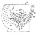
도 1은 질관 내에 위치하고, 치골결합과 상호 작용하여 요도 튜브가 압축될 수 있게 하고 증가된 복강내압의 발작 동안의 요실금을 경감시키는 요실금자용 장 치의 한 실시태양을 나타내는 인체의 정중시상면 절단도이다.1 is a median sagittal cross-sectional view of a human body showing an embodiment of an urinary incontinence device located in the vaginal canal that interacts with the pubic bone to allow the urethral tube to be compressed and relieve incontinence during increased intraperitoneal pressure attacks. .
도 2는 질관 내에 위치하고, 치골결합과 상호 작용하여 요도 튜브가 압축될 수 있게 하고 증가된 복강내압의 발작 동안의 요실금을 경감시키는 요실금자용 장치의 또다른 실시태양을 나타내는 인체의 정중시상면 절단도이다.FIG. 2 is a median sagittal view of a human body showing another embodiment of an urinary incontinence device located in the vaginal canal and interacting with the pubic bone to allow the urethral tube to compress and relieve incontinence during increased intraperitoneal pressure attacks; to be.
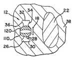
도 3은 요실금자용 장치의 다리가 전방 질벽 및 후방 질벽과 접촉하는, 도 1의 3-3선을 따라 얻은 단면도이다.3 is a cross-sectional view taken along line 3-3 of FIG. 1, with the legs of the urinary incontinence device in contact with the anterior vaginal wall and the posterior vaginal wall.
도 4는 요실금자용 장치의 다리가 좌측 질벽 및 우측 질벽과 접촉하는 것을 제외하고는 도 1의 3-3선을 따라 얻은 단면도이다.4 is a cross-sectional view taken along line 3-3 of FIG. 1 except that the legs of the urinary incontinence device are in contact with the left and right vaginal walls.
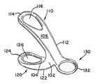
도 5는 장치의 다리가 장치가 삽입될 때 상향 위치인 본 발명의 요실금자용 장치의 한 실시태양의 사시도이다. 바꾸어 말하면, 다리는 장치가 사용될 때 자궁목에 인접한다.5 is a perspective view of one embodiment of the incontinence device of the present invention in which the leg of the device is in an upward position when the device is inserted. In other words, the legs are adjacent to the cervical neck when the device is used.
도 6은 장치의 다리가 장치가 삽입될 때 상향 위치인 본 발명의 요실금자용 장치의 또다른 실시태양의 사시도이다. 바꾸어 말하면, 다리는 장치가 사용될 때 자궁목에 인접한다.6 is a perspective view of another embodiment of the incontinence device of the present invention in which the leg of the device is in an upward position when the device is inserted. In other words, the legs are adjacent to the cervical neck when the device is used.
도 7은 장치의 다리가 장치가 삽입될 때 하향 위치이고, 부재가 각각의 다리의 원위 말단에서 제거 부재를 포함하는, 본 발명의 요실금자용 장치의 또다른 실시태양의 사시도이다.FIG. 7 is a perspective view of another embodiment of the incontinence device of the present invention wherein the legs of the device are in a downward position when the device is inserted and the member includes a removal member at the distal end of each leg.
도 8은 장치의 다리가 장치가 삽입될 때 상향 위치이고, 장치가 각각의 다리의 원위 말단에서 제거 부재 및 삽입기 (도시되지 않음)와 상호 작용하는 삽입 부재를 포함하는 부재를 포함하는, 본 발명의 요실금자용 장치의 또다른 실시태양의 사시도이다.FIG. 8 shows that the legs of the device are in an upward position when the device is inserted, and wherein the device includes a member including a removal member and an insertion member that interacts with an inserter (not shown) at the distal end of each leg. Is a perspective view of another embodiment of the incontinence device of the invention.
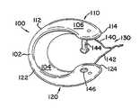
도 9는 장치의 다리가 장치가 삽입될 때 상향 위치이고, 장치가 각각의 다리의 원위 말단에서 제거 부재 및 삽입기 (도시되지 않음)와 상호 작용하는 삽입 부재를 포함하는 부재를 포함하는, 본 발명의 요실금자용 장치의 또다른 실시태양의 사시도이다.FIG. 9 shows that the legs of the device are in an upward position when the device is inserted, and wherein the device includes a member including a removal member and an insertion member that interacts with an inserter (not shown) at the distal end of each leg. Is a perspective view of another embodiment of the incontinence device of the invention.
도 10은 장치의 다리가 장치가 삽입될 때 상향 위치이고, 장치가 각각의 다리의 원위 말단에서 제거 부재 및 삽입기 (도시되지 않음)와 상호 작용하는 삽입 부재를 포함하는 부재를 포함하는, 본 발명의 요실금자용 장치의 또다른 실시태양의 사시도이다.FIG. 10 shows that the legs of the device are in an upward position when the device is inserted, and wherein the device includes a member including a removal member and an insertion member that interacts with an inserter (not shown) at the distal end of each leg. Is a perspective view of another embodiment of the incontinence device of the invention.
도 11은 장치의 다리가 장치가 삽입될 때 상향 위치이고, 장치가 삽입기와 상호 작용하는 각각의 다리의 원위 말단에서의 삽입 및 제거 부재를 포함하는 부재를 포함하는, 본 발명의 요실금자용 장치의 또다른 실시태양의 사시도이다.FIG. 11 is an incontinence device of the present invention wherein the legs of the device are in an up position when the device is inserted, including members including insertion and removal members at the distal end of each leg with which the device interacts with the inserter. Is a perspective view of another embodiment.
도 12는 장치의 다리가 장치가 삽입될 때 상향 위치이고, 장치가 삽입기 및/또는 제거기와 연결되는 각각의 다리의 근위 말단에서 삽입 및 제거 부재를 포함하는 부재를 포함하여 다리가 서로 근접하고 장치가 질 내로 삽입되기가 쉬운 도 11의 요실금자용 장치의 실시태양의 사시도이다.12 shows the legs of the device in an upward position when the device is inserted, the legs being close to each other including a member comprising an insertion and removal member at the proximal end of each leg to which the device is connected with the inserter and / or the remover. 11 is a perspective view of an embodiment of the urinary incontinence device of FIG. 11 that is easy to insert into the vagina.
도 1 및 2를 살펴보면, 여성의 인체 (10)가 질 (12), 자궁목 (14), 자궁 (16), 요도 (18), 방광 (20) 및 치골결합 (22)과 함께 도시된다. 질 (12)은 인체 (10)를 나가는 질입구 (24)를 갖고, 질입구 (24)로부터 자궁목 (14)까지 연장되는 질관 (26)을 포함한다. 질관 (26)은 대부분의 여성에서 약 4 인치 내지 약 6 인치 (약 102 mm 내지 약 153 mm)로 변하는 범위의 길이를 갖는다. 자궁목 (14)은 자궁으로의 입구이고, 질관 (26)의 상부측 및 자궁 (16) 사이에 위치한다. 직장 (27)은 질 (12) 후방에 위치한다. 질관 (26)은 내부 주변부 (28)를 갖는다.1 and 2, a female
도 3 및 4에서 가장 잘 나타낸 바와 같이, 내부 주변부 (28)는 우측벽 (30), 좌측벽 (32), 전방벽 (34) 및 후방벽 (36)으로 이루어진다. 4개의 벽 (30, 32, 34 및 36)은 내부 주변부 (28)의 전체 360 도를 둘러싼다. 전방벽 (34)는 요도 (18)에 가장 근접하게 위치하고, 요도 (18)은 치골결합 (22) 및 질 (12) 사이에 위치한다.As best shown in FIGS. 3 and 4, the
질관 (26)은 각각이 전체 길이의 약 1/3을 나타내는, 3가지 대략 동일한 부분으로 나누어질 수 있다. 각각의 부분은 길이가 대략 2 인치 (대략 51 mm)이다. 질관 (26)의 세부분 중 가운데가, 요도 (18)에 근접하기 때문에 여성 요실금을 경감시키는데 가장 중요한 부분이며, 요실금자용 장치가 위치되어야 하는 위치이다. 또한, 질관 (26)의 세부분 중 가운데가 치골결합 (22)로부터 수평적으로 어긋나 있으며, 이는 인체 (10)의 정면부 (38)에 인접하게 위치한 뼈 융기부이다. 질 (12) 내에 위치한 요실금자용 장치 및 치골결합 (22) 사이의 상호 작용은 요도 (18)를 압축시켜 방광으로부터의 불수의적 요 흐름을 경감시키게 한다.
또한, 요도 튜브로도 불리는 요도 (18)는 인체 (10)으로부터 나가는 제1 개구 (40)로부터 방광 (20)의 하부면에 위치한 제2 개구 (42)까지 연장되어 있는 할로우 튜브이다. 요도 (18)는 대부분의 여성에서 약 1.5 인치 (약 38 mm)의 길이를 갖는다. 요도는 방광 (20)에 일시적으로 저장된 요를 인체로부터 배출하는 작용을 한다. 요도 (18)는 내부 주변부의 길이를 따라 위치한 다수의 요도조임근 (44)를 갖는다. 요도조임근 (44)는 개구 (42) 보다 아래에 위치하며, 요의 통과를 방지하기 위해 정상적으로 요도 (18)의 수축을 유지하는 고리형 근육이다. 정상적인 생리적 작용에 의한 요도조임근 (44)의 이완은 신체로부터 요를 수의적으로 배출시킬 수 있다.The
다시 도 1 및 2를 보면, 인체 (10)은 질 (12) 및 치골결합 (22) 사이에 위치한 요도질근막 구역 (46)에 위치한 근조직 및 신체 조직을 포함한다. 방광 (20)은 치골결합 (22) 후방에 놓이고, 질 (12) 및 자궁 (16)에 의해 직장 (27)과 분리된다. 요를 신장으로부터 방광 (20)까지 수송하는 요관 (도시되지 않음)은 골반으로부터 방광 (20) 후방측까지 지나간다. 요관 양쪽 모두가 종결되는 방광저 (48)은 질 (12)의 전방벽 (34)에 인접하게 위치한다.Referring again to FIGS. 1 and 2, the
도 1 및 2를 보면, 요실금자용 장치 (100)은 질관 (26) 내에 위치하여 도시된다. 요실금자용 장치 (100)은 요도질근막 구역 (46) 내에 위치한 근조직 및 신체 조직을 지지하도록 질을 가로질러 다리를 놓도록 디자인되었다.1 and 2, the
도 3 및 4에서는, 요실금자용 장치 (100)은 벌어진 상태로 도시되었다. 요실금자용 장치 (100)의 일부, 특히 제1 다리 (110) 및 제2 다리 (120)은 각각 우측 및 좌측벽 (30 및 32)을 직접 접촉하거나 또는 각각 전방 및 후방벽(34 및 36)을 직접 접촉하여 요도 튜브 (18)에 대한 지지 배경을 제공한다. 요도 튜브 (18)은 충분히 압축되어 요의 흐름을 차단하고 요도조임근 (44)에 대한 지지부를 제공하여 적합하게 작용할 수 있게 할 수 있다. 요실금자용 장치 (100) 및 치골결합 (22) 사이에 요도 튜브 (18)을 압축시켜 방광으로부터의 요의 불수의적 흐름을 제한한다.3 and 4, the
도 5를 보면, 요실금자용 장치 (100)의 한 실시태양이 도시되어 있다. 장치 (100)은 제1 다리 (110)을 제2 다리 (120)으로 연결하여 전체적으로 "C-형" 형상을 형성하게 하는 기저부 (102)를 갖는다. 장치는 내부면 (104) 및 외부면 (106)을 가지며, 양 표면 모두 매끈한 에지 및/또는 윤곽을 가져 장치 (100)의 삽입, 배치 및 회수에서의 임의의 불편함을 최소화시킨다.5, one embodiment of the
바람직하게는, 장치 (100)은 단일 구조일 수 있고, 탄성을 갖는 불활성 생친화성 합성 수지를 성형하여 형성될 수 있다. 한가지 이러한 수지는 성형된 실리콘 화합물, 폴리우레탄 또는 다른 적절한 생친화성 물질, 또는 이 물질들의 조합물이다. 어떠한 경우에서도, 단일 구조로 또는 다른 방식으로 제조된 장치 (100)은 당업계에 공지된 적절한 생친화성 물질로 제조된다.Preferably, the
기저부 (102)는 다리 (110, 120)을 외향으로 편향시키지만 충분히 탄성이어서 다리 (110, 120)이 서로를 향한 방향으로 압축되어 장치 (100)의 삽입이 간단하게 되게 하는 가요성 물질로 형성된다.The
제1 다리 (110)은 기저부 (102)와 연결되는 근위 말단 (112) 및 근위 말단 (112)로부터 연장되는 원위 말단 (114)를 갖는다. 유사하게, 제2 다리 (120)은 기저부 (102)와 연결되는 근위 말단 (122) 및 근위 말단 (122)로부터 연장되는 원위 말단 (124)를 갖는다. 각각의 다리는 약 40 mm로 내지 약 70 mm, 바람직하게는 약 50 mm 내지 약 60 mm, 더욱 바람직하게는 약 55 mm의 길이를 갖는다.The
원위 말단 (114 및 124)는 만곡된 프로파일을 나타내어 임의의 불편함을 최소화한다. 정상적으로, 원위 말단은 약 0.125 인치 내지 약 0.9375 인치, 바람직하게는 약 0.5625 인치 내지 약 0.8125 인치, 더욱 바람직하게는 약 0.75 인치의 만곡 반경을 갖는다.Distal ends 114 and 124 exhibit a curved profile to minimize any discomfort. Normally, the distal end has a bend radius of about 0.125 inches to about 0.9375 inches, preferably about 0.5625 inches to about 0.8125 inches, more preferably about 0.75 inches.
도 6에 도시된 바와 같이, 한 실시태양에서는, 제1 다리 (110)의 원위 말단 (114)가 구멍 (116)과 함께 제공되어 재료 값을 경감시키고 사용시 더욱 큰 편리함을 제공할 수 있다. 이러한 실시태양과 유사하게, 제2 다리 (120)의 원위 말단 (124)는 구멍 (126)과 함께 제공될 수 있다.As shown in FIG. 6, in one embodiment, the
또한, 장치 (100)은 질 내로 장치를 삽입하거나, 질로부터 장치를 회수하거나 또는 양쪽 모두를 하는데 사용될 수 있는 부재 (130)을 가진다. 이와 관련하여, 도 5 및 6을 보면, 부재 (130)은 기저부 (102)의 외부면 (106) 상에 존재하며, 외향으로 연장된다. 이 실시태양에서 부재 (130)은 임의의 적절한 형태를 취할 수 있지만, 정상적으로 만곡형을 가져 임의의 과도한 마찰 또는 기타 자극을 최소화시킨다. 부재 (130)은 중심 구멍을 갖는 고리형 부재 (132)로서 도 5 및 6에 도시되어 있다.The
도 5 및 6에 도시된 실시태양에서는, 장치 (100)은 적합한 위치에서 도 1에 도시된 바와 같이 다리 (110, 120)이 상향으로 연장되어 놓이면서 장치 (100)이 하향으로 오목하게 되도록 질 (12) 내로 삽입된다. 게다가, 장치 (100)은 제1 다리 (110)가 우측 질벽 (30)과 직접 접촉하고, 제2 다리 (120)이 좌측 질벽 (32)과 직접 접촉하도록 선택적으로 위치시킬 수 있다. 다르게는, 장치 (100)은 제1 다리 (110)이 전방벽 (34)과 접촉하고, 제2 다리 (120)이 후방벽 (36)과 접촉하도록 선택적으로 위치시킬 수 있다.In the embodiment shown in FIGS. 5 and 6, the
도 7 내지 9를 살펴보면, 본 발명의 다른 실시태양이 도시되어 있다. 또한, 이들 실시태양의 장치 (100)은, 사용시 다리 (110, 120)이 하향으로 연장되고 장치 (100)이 상향으로 볼록한 위치로 나타내는 것을 제외하고, 전체적으로 "C-형" 장치이다. 도 7을 구체적으로 보면, 장치 (100)은 제1 다리 (110)의 원위 말단 (114)로부터 연장되는 끈의 형태인 제1 제거 부재 (140) 및 제2 다리 (120)의 원위 말단 (124)로부터 연장되는 역시 끈의 형태인 제2 제거 부재 (142)를 포함하는 부재 (130)을 갖는다.7-9, another embodiment of the present invention is shown. Also, the
도 8에 도시된 바와 같은 다른 실시태양에서는, 부재 (130)은 제1 제거 부재 (140), 제2 제거 부재 (142), 제1 삽입 부재 (144) 및 제2 삽입 부재 (146)을 포함한다. 제1 제거 부재 (140)은 제1 다리 (110)의 원위 말단 (114)로부터 연장되는 끈의 형태이다. 제2 제거 부재 (142) 또한 제2 다리 (120)의 원위 말단 (124)로부터 연장되는 끈의 형태이다. 제1 삽입 부재 (144)는 제1 다리 (110)의 원위 말단 (114)의 내부면 (104)으로부터 연장되고, 제2 다리 (120)의 원위 말단 (124)의 내부면 (104)으로부터 연장되는 제2 삽입 부재 (146)와 상호 작용적으로 결합된다. 이와 같이, 제1 삽입 부재 (144)는 제2 삽입 부재 (146)과 상호 작용하여 적절한 삽입 기구 (도시되지 않음)를 사용하여 질 (12) 내로 장치 (100)를 삽입하기 위해 서로 인접한 다리 (110, 120)의 원위 말단 (114, 124)를 위치시키고 유지시킨다. 삽입 기구는 장치 (100)을 선택적으로 위치시킬 뿐만 아니라 제2 삽입 부재 (146)과 상호 작용적인 결합으로부터 제1 삽입 부재 (144)를 배출하기도 한다.In another embodiment as shown in FIG. 8, the
도 9에 가장 잘 도시된 바와 같은 또다른 실시태양에서는, 부재 (130)은 제1 다리 (110)의 원위 말단 (114)의 외부면 (106) 상에 제공되는 제1 삽입 부재 (244)를 포함한다. 동일한 제2 삽입 부재 (도시되지 않음)가 유사하게 제2 다리 (120)의 원위 말단 (124)의 외부면 (106) 상에 제공된다. 삽입 기구 (도시되지 않음)는 제1 다리 (110)을 제2 다리 (120)을 향하게 편향시켜 질 (12) 내로의 삽입을 위한 장치 (100)의 더 작은 프로파일을 생기게 한다. 또한, 삽입 기구는 장치 (100)을 선택적으로 위치시키고, 배출시 다리 (110 및 120)가 우측 및 좌측 질벽 (30, 32) 또는 전방 및 후방 질벽 (34, 36)과 접촉하도록 선택적으로 외향으로 편향된다.In another embodiment, as best shown in FIG. 9, the
도 10에 도시된 또다른 실시태양에서는, 부재 (130)이 제1 다리 (110)의 원위 말단 (114)의 내부면 (104) 상에 제공되는 제1 삽입 부재 (344) 및 제2 다리 (120)의 원위 말단 (124)의 내부면 (104) 상에 제공되는 제2 삽입 부재 (346)을 포함한다. 삽입 기구 (도시되지 않음)는 제1 다리 (110)을 제2 다리 (120)을 향해 편향시켜 질 (12) 내로 장치 (100)의 삽입을 위한 더 작은 프로파일을 생기게 한다. 또한, 삽입 기구는 장치 (100)을 선택적으로 위치시키고, 배출시 다리 (110 및 120)가 우측 및 좌측 질벽 (30, 32) 또는 전방 및 후방 질벽 (34, 36)과 접촉하도록 선택적으로 외향으로 편향된다.In another embodiment shown in FIG. 10, the
도 11 및 12를 살펴보면, 본 발명의 요실금자용 장치 (100)의 또다른 실시태양이 도시되어 있다. 이 실시태양에서는, 삽입 및 제거 부재 (130)이 기저부 (102)에 인접하여 제공된다. 특히, 삽입 및 제거 부재 (130)은 각각 다리 (110, 120)의 근위 (112, 122)에서 외부면 (106) 상에 제공되는 제1 오목부 (444) 및 제2 오목부 (446)을 포함한다. 오목부 (444, 446)은 삽입/제거 기구 (500) 상에 제공되는 각각의 플랜지 (502, 504)와 상호 작용한다.11 and 12, another embodiment of the
도 12에 더욱 구체적으로 도시된 바와 같이, 플랜지 (502, 504)는 각각의 오목부 (444, 446)과 결합하여 제1 다리 (110)을 제2 다리 (120)을 향해 편향시켜 질 내로의 삽입 및 질로부터의 제거를 위한 장치 (100)의 더 작은 프로파일을 생기게 한다.As more specifically shown in FIG. 12, the
상기에 기재된 바와 같은 본 발명의 장치는 1회 사용 후에 처분되거나, 1회 보다 더 많이 착용되거나 또는 처분되기 전에 일정한 기간 (예를 들어, 1주일) 동안 재사용할 수 있다.The device of the present invention as described above may be disposed of after a single use, worn more than once, or reused for a period of time (eg, one week) before being disposed of.
본 발명은 구체적인 실시태양과 함께 기술되었지만, 많은 다른 방법, 변경 및 변형이 앞선 기재로부터 당업자에게 명백할 수 있다. 따라서, 본 발명은 청구의 범위의 취지 및 범위 내에 속하는 이러한 모든 다른 방법, 변경 및 변형을 내포하도록 의도된 것이다.While the present invention has been described in conjunction with specific embodiments, many other methods, modifications, and variations may be apparent to those skilled in the art from the foregoing description. Accordingly, the present invention is intended to embrace all such other methods, modifications, and variations that fall within the spirit and scope of the claims.
Claims (20)
Translated fromKoreanApplications Claiming Priority (2)
| Application Number | Priority Date | Filing Date | Title |
|---|---|---|---|
| US10/246,005US6676594B1 (en) | 2002-09-18 | 2002-09-18 | C-shaped vaginal incontinence insert |
| US10/246,005 | 2002-09-18 |
Related Child Applications (1)
| Application Number | Title | Priority Date | Filing Date |
|---|---|---|---|
| KR1020117007336ADivisionKR20110036653A (en) | 2002-09-18 | 2003-05-20 | Vaginal Inserts for C-Type Incontinence |
Publications (2)
| Publication Number | Publication Date |
|---|---|
| KR20050042797A KR20050042797A (en) | 2005-05-10 |
| KR101040414B1true KR101040414B1 (en) | 2011-06-09 |
Family
ID=29780334
Family Applications (2)
| Application Number | Title | Priority Date | Filing Date |
|---|---|---|---|
| KR1020057003696AExpired - LifetimeKR101040414B1 (en) | 2002-09-18 | 2003-05-20 | Vaginal Inserts for C-Type Incontinence |
| KR1020117007336ACeasedKR20110036653A (en) | 2002-09-18 | 2003-05-20 | Vaginal Inserts for C-Type Incontinence |
Family Applications After (1)
| Application Number | Title | Priority Date | Filing Date |
|---|---|---|---|
| KR1020117007336ACeasedKR20110036653A (en) | 2002-09-18 | 2003-05-20 | Vaginal Inserts for C-Type Incontinence |
Country Status (8)
| Country | Link |
|---|---|
| US (1) | US6676594B1 (en) |
| EP (1) | EP1539027A2 (en) |
| KR (2) | KR101040414B1 (en) |
| AU (1) | AU2003233612B2 (en) |
| BR (1) | BR0314016B1 (en) |
| CA (1) | CA2497907C (en) |
| MX (1) | MXPA05002395A (en) |
| WO (1) | WO2004026172A2 (en) |
Families Citing this family (44)
| Publication number | Priority date | Publication date | Assignee | Title |
|---|---|---|---|---|
| WO2004103213A1 (en)* | 2003-05-22 | 2004-12-02 | Contipi Ltd. | Device for the prevention of urinary incontinence in females |
| MXPA06010653A (en) | 2004-03-18 | 2007-03-26 | Contipi Ltd | Apparatus for the prevention of urinary incontinence in females. |
| WO2005087153A2 (en)* | 2004-03-18 | 2005-09-22 | Contipi Ltd. | Apparatus for the treatment of feminine pelvic organ prolapse |
| AU2006210494B2 (en)* | 2005-02-04 | 2011-01-06 | Ams Research Corporation | Needle design for male transobturator sling |
| JP2008537497A (en)* | 2005-03-17 | 2008-09-18 | コンティピ リミテッド | Urinary incontinence improvement device for women |
| IL176883A (en) | 2005-09-22 | 2013-09-30 | Eliahu Eliachar | Apparatus for the amelioration of urinary incontinence in females |
| US8613698B2 (en)* | 2006-07-10 | 2013-12-24 | Mcneil-Ppc, Inc. | Resilient device |
| WO2008008794A2 (en)* | 2006-07-10 | 2008-01-17 | Mc Neil-Ppc, Inc. | Resilient device |
| US10219884B2 (en) | 2006-07-10 | 2019-03-05 | First Quality Hygienic, Inc. | Resilient device |
| US7717892B2 (en)* | 2006-07-10 | 2010-05-18 | Mcneil-Ppc, Inc. | Method of treating urinary incontinence |
| US10004584B2 (en) | 2006-07-10 | 2018-06-26 | First Quality Hygienic, Inc. | Resilient intravaginal device |
| US7455567B2 (en)* | 2006-08-02 | 2008-11-25 | Hanesbrands Inc. | Garments having auxetic foam layers |
| RU2479284C2 (en)* | 2007-06-11 | 2013-04-20 | Контипи Лтд. | Tension-adjusted ring for female urinary incontinence relief |
| US9339363B2 (en) | 2007-10-01 | 2016-05-17 | Kimberly Clark Worldwide, Inc. | Management of urinary incontinence in females |
| US8651109B2 (en)* | 2008-04-23 | 2014-02-18 | Contipi Ltd. | Pessaries for prolapse alleviation |
| JP5525043B2 (en) | 2009-05-28 | 2014-06-18 | コンタイン コーポレーション | Correction of stress urinary incontinence |
| US20110152604A1 (en)* | 2009-12-23 | 2011-06-23 | Hull Jr Raymond J | Intravaginal incontinence device |
| US9072578B2 (en) | 2010-03-16 | 2015-07-07 | Pelvalon, Inc. | Intra-vaginal device for fecal incontinence |
| US9289278B2 (en) | 2010-03-16 | 2016-03-22 | Pelvalon, Inc. | Intra-vaginal devices and methods for treating fecal incontinence |
| US9022919B2 (en) | 2010-12-23 | 2015-05-05 | Kimberly-Clark Worldwide, Inc. | Vaginal insert device having a support portion with plurality of struts |
| US9814630B2 (en) | 2010-12-23 | 2017-11-14 | Kimberly-Clark Worldwide, Inc. | Vaginal insert device having a support portion with plurality of foldable areas |
| JP2014530678A (en) | 2011-09-22 | 2014-11-20 | ペルヴァロン・インコーポレイテッド | Intravaginal device and method for treating fecal incontinence |
| US8911344B2 (en) | 2011-12-20 | 2014-12-16 | Kimberly-Clark Worldwide, Inc. | Vaginal insert device having perpendicular segments |
| US9320640B2 (en) | 2012-06-29 | 2016-04-26 | The Procter & Gamble Company | Method of attaching a withdrawal member to a pessary device |
| US9439748B2 (en)* | 2012-10-10 | 2016-09-13 | The Procter & Gamble Company | Pessary device |
| US9999490B2 (en) | 2013-02-14 | 2018-06-19 | Pelvalon, Inc. | Intra-vaginal devices and methods for treating fecal incontinence |
| US9216105B2 (en) | 2013-03-14 | 2015-12-22 | Medicele, Llc. | Rectocele and cystocele device |
| US9072582B2 (en) | 2013-03-14 | 2015-07-07 | Ryan Maaskamp | Rectocele device |
| US9186234B2 (en) | 2013-04-23 | 2015-11-17 | Terell Reglin | Apparatus for promoting urorectal organ emptying and related method |
| WO2016112107A1 (en)* | 2015-01-06 | 2016-07-14 | Jacky Lee | Intravaginal device for alleviating incontinence |
| KR101721040B1 (en) | 2015-12-23 | 2017-03-29 | 주식회사 엘지생활건강 | Urinary incontinence protecting apparatus |
| ES2842380T3 (en) | 2016-07-25 | 2021-07-13 | Ovala Inc | Incontinence device |
| US10441402B2 (en) | 2016-07-25 | 2019-10-15 | Rinovum Subsidiary 2, LLC | Incontinence device |
| WO2018140192A1 (en) | 2017-01-24 | 2018-08-02 | Liv Labs Inc. | Stress urinary incontinence (sui) device |
| AU2018257495B2 (en) | 2017-04-26 | 2023-09-14 | Ovala, Inc. | Introducer for urinary incontinence device |
| US10849659B2 (en) | 2017-05-25 | 2020-12-01 | Mikisha Haeri | Fertility device and method of use, operation, and manufacture |
| USD833009S1 (en) | 2017-07-24 | 2018-11-06 | Rinovum Subsidiary 2, LLC | Incontinence device |
| USD832437S1 (en) | 2017-07-24 | 2018-10-30 | Rinovum Subsidiary 2, LLC | Incontinence device |
| USD835273S1 (en)* | 2017-07-25 | 2018-12-04 | Life360 Innovations Inc. | Urethral plug inserter |
| EP4223210A1 (en)* | 2017-11-10 | 2023-08-09 | Hegenbergerspeculum APS | Device |
| US11259957B2 (en) | 2019-09-25 | 2022-03-01 | Ryan Maaskamp | Rectocele guide |
| KR102081032B1 (en)* | 2019-11-01 | 2020-02-24 | 김계환 | Device for treating unrinary incontinence and panties having the same |
| USD1071181S1 (en) | 2022-04-20 | 2025-04-15 | Liv Labs Inc. | Urinary incontinence device |
| CN114848228B (en)* | 2022-05-23 | 2023-04-11 | 江苏泰科博曼医疗器械有限公司 | Auxiliary pressing device for stress urinary incontinence |
Citations (2)
| Publication number | Priority date | Publication date | Assignee | Title |
|---|---|---|---|---|
| US5036867A (en) | 1986-10-14 | 1991-08-06 | Zedlani Pty. Limited | Urinary incontinence device |
| US5618256A (en) | 1993-08-20 | 1997-04-08 | Coloplast A/S | Device for arrangement in vagina for prevention of involuntary urination with females and an applicator for use in insertion of the device |
Family Cites Families (141)
| Publication number | Priority date | Publication date | Assignee | Title |
|---|---|---|---|---|
| US1790801A (en) | 1931-02-03 | Louis dickstehst | ||
| US1280979A (en) | 1917-06-12 | 1918-10-08 | Avard A Ellis | Tampon. |
| US2092427A (en) | 1932-07-13 | 1937-09-07 | Ross Frederick Alexnader | Catamenial device |
| US2057206A (en) | 1933-10-31 | 1936-10-13 | Meyer S Marks | Hygienic catamenial tampon |
| US2264586A (en) | 1937-06-24 | 1941-12-02 | Ross Frederick Alexander | Catamenial device |
| US2201412A (en) | 1937-09-27 | 1940-05-21 | Stein Jacob | Tampon |
| US2355628A (en) | 1941-01-18 | 1944-08-15 | Calhoun Vernon | Catamenial device and method of making same |
| US2298752A (en) | 1941-04-18 | 1942-10-13 | Joseph R Crockford | Tampon |
| US2401585A (en) | 1943-08-04 | 1946-06-04 | Leon S Seidler | Depositor and applicator |
| US2487200A (en) | 1946-07-16 | 1949-11-08 | Margaret W Trager | Tampon |
| US2501972A (en) | 1946-07-31 | 1950-03-28 | Leon S Seidler | Depositor and applicator |
| US2491017A (en) | 1946-09-28 | 1949-12-13 | Vera E Robinson | Tampon with built-in applicator |
| US2700188A (en) | 1948-05-11 | 1955-01-25 | Curlator Corp | Fiber web forming machine |
| US2519912A (en) | 1948-07-03 | 1950-08-22 | Laun Hellmut | Tampon |
| US2711173A (en) | 1954-01-15 | 1955-06-21 | Leon S Seidler | Depositors and applicators |
| US2739593A (en) | 1954-02-25 | 1956-03-27 | Zonite Products Corp | Medicated vaginal tampons |
| US2890497A (en) | 1954-03-10 | 1959-06-16 | Curlator Corp | Machine for forming random fiber webs |
| US2938519A (en) | 1957-02-08 | 1960-05-31 | John L Marco | Bodily orifice seal |
| US3011495A (en) | 1958-02-11 | 1961-12-05 | Personal Products Corp | Absorbent product |
| US3079921A (en) | 1959-04-17 | 1963-03-05 | Johnson & Johnson | Absorbent product |
| DE1815375U (en) | 1960-02-01 | 1960-07-21 | Wilhelm H Esser | TYING THREAD FOR AGRICULTURAL PURPOSES MADE OF PLASTIC. |
| US3034508A (en) | 1960-10-19 | 1962-05-15 | Jr George S Nalle | Molded tampon applicators |
| US3032036A (en) | 1960-10-19 | 1962-05-01 | Rader Sidney | Applicator for treating hemorrhoids |
| US3090385A (en) | 1960-12-05 | 1963-05-21 | Johnson & Johnson | Tampon applicator |
| US3138159A (en) | 1961-02-15 | 1964-06-23 | Johnson & Johnson | Absorbent product |
| NL145138B (en) | 1964-08-04 | Hahn Carl Dr Kg | APPLICATOR WITH TAMPON. | |
| US3369544A (en) | 1965-03-31 | 1968-02-20 | Kimberly Clark Co | Catamenial tampon |
| US3469286A (en) | 1965-03-31 | 1969-09-30 | Kimberly Clark Co | Method for fabricating compressed and folded absorbent tampons |
| JPS49116B1 (en) | 1965-06-11 | 1974-01-05 | ||
| GB1105885A (en) | 1965-09-14 | 1968-03-13 | Giuseppe De Crescenzo | Improvements in or relating to absorbent tampons or pessaries |
| GB1115727A (en) | 1965-11-15 | 1968-05-29 | Harry Hall Tomkin | Apparatus controlling incontinence in the female |
| US3543754A (en) | 1967-10-16 | 1970-12-01 | Jones Sr John L | Tampon applicator |
| US3554184A (en) | 1968-04-17 | 1971-01-12 | Henry N Habib | Pubo-vaginal incontinence device |
| GB1289107A (en) | 1968-12-10 | 1972-09-13 | ||
| US3643661A (en) | 1969-07-15 | 1972-02-22 | Kimberly Clark Co | Tampon for directional placement and applicator therefor |
| US3705575A (en) | 1969-09-26 | 1972-12-12 | Lynn Euryl Edwards | Incontinence device for female use |
| US3596328A (en) | 1969-10-09 | 1971-08-03 | Joseph A Voss | Method of making catamenial devices |
| US3706311A (en) | 1970-11-27 | 1972-12-19 | Procter & Gamble | Self-spreading catamenial tampon |
| US3765417A (en) | 1971-02-24 | 1973-10-16 | Kimberly Clark Co | Arcuate tampon applicator |
| SE364634B (en) | 1971-05-25 | 1974-03-04 | Svenska Cellulosa Ab | |
| JPS50989B2 (en) | 1971-09-10 | 1975-01-14 | ||
| US3762413A (en) | 1972-06-21 | 1973-10-02 | Kimberly Clark Co | Tampon with multiple strings |
| US4011034A (en) | 1972-07-08 | 1977-03-08 | Karl Kroyer St. Anne's Limited | Production of fibrous sheet material |
| US4160004A (en) | 1972-07-08 | 1979-07-03 | Karl Kroyer St. Anne's Limited | Production of fibrous sheet material |
| GB1452262A (en) | 1972-07-13 | 1976-10-13 | Devices Implants Ltd | Pessary ring electrode system |
| GB1359343A (en) | 1972-11-07 | 1974-07-10 | Levy N | Pneumatic inhibitor for female incontinence |
| FR2228464A1 (en) | 1973-05-10 | 1974-12-06 | Heguy Michelle | Incontinent female patient ureter blocking device - is of flexible material with balloon compressing urethra |
| US3918452A (en) | 1974-08-01 | 1975-11-11 | Edward Cornfeld | Tampons impregnated with contraceptive compositions |
| US3971378A (en) | 1974-12-20 | 1976-07-27 | Ortho Pharmaceutical Corporation | Expansible tampon |
| GB1497807A (en) | 1975-01-18 | 1978-01-12 | Kroyer St Annes Ltd Karl | Method and apparatus for dry forming a layer of fibre |
| GB1497808A (en) | 1975-05-29 | 1978-01-12 | Kroyer St Annes Ltd Karl | Apparatus for dry forming a layer of fibre |
| US4019498A (en) | 1975-06-27 | 1977-04-26 | The University Of Iowa Research Foundation | Device for control of female urinary incontinence |
| US3983875A (en) | 1976-02-05 | 1976-10-05 | Kimberly-Clark Corporation | Tampon-inserter stick combination with a modified stick-receiving socket |
| FR2342717A1 (en) | 1976-03-02 | 1977-09-30 | Levy Nellie | Female urine incontinence inhibition device - has air release valve to deflate bladder inserted into vagina and inflated by pump hidden in clothing |
| GB1516573A (en) | 1976-04-02 | 1978-07-05 | Kroyer St Annes Ltd Karl | Dry-laying a web of particulate or fibrous material |
| DE2721511C2 (en) | 1976-05-12 | 1985-11-28 | Honshu Seishi K.K., Tokyo | Adsorbent nonwoven fabric and process for its manufacture |
| US4139006A (en) | 1977-03-18 | 1979-02-13 | Corey Arthur E | Female incontinence device |
| US4148317A (en) | 1977-09-14 | 1979-04-10 | Personal Products Company | Reduced length tampon-applicator assembly |
| DE2747245A1 (en) | 1977-10-21 | 1979-04-26 | Walter Koss | Resilient plug for anus - has support plate carrying flexible skin filled with soft rubber or plastics foam material |
| DK144382C (en) | 1977-11-08 | 1982-07-26 | Kroyer K K K | Apparatus for the preparation of a web-shaped fiber product |
| US4212301A (en) | 1978-08-14 | 1980-07-15 | Kimberly-Clark Corporation | Digital tampon |
| DE2855179C2 (en) | 1978-12-20 | 1982-06-09 | Dr. Carl Hahn GmbH, 4000 Düsseldorf | Feminine hygiene tampon |
| US4266546A (en) | 1980-02-25 | 1981-05-12 | Kimberly-Clark Corporation | Wrapped folded tampons |
| US4307716A (en) | 1980-04-11 | 1981-12-29 | Davis Alwyn K | Invaginate supported ovoid pessary |
| US4318407A (en) | 1980-08-28 | 1982-03-09 | Kimberly-Clark Corporation | Folded tampon pledget |
| US4398532A (en) | 1980-12-12 | 1983-08-16 | Sweeney Iii William J | Insertion device for a diaphragm |
| US4335721A (en) | 1981-02-17 | 1982-06-22 | Kimberly-Clark Corporation | Tampon containing fusible portions |
| DE3122954C2 (en) | 1981-06-10 | 1983-04-14 | Temca Chemische Union GmbH, 8500 Nürnberg | A tampon made of open-cell plastic foam for hygienic or medical purposes |
| US4498899A (en) | 1982-04-05 | 1985-02-12 | Ethyl Molded Products Company | Tampon applicator |
| US4486191A (en) | 1982-08-12 | 1984-12-04 | Technology Unlimited Inc. | Tampon |
| US4516570A (en) | 1982-08-27 | 1985-05-14 | Taban Charles H | Pessary |
| CA1242124A (en) | 1983-09-27 | 1988-09-20 | Thomas G. Eakin | Incontienence devices for women |
| GB2146901B (en)* | 1983-09-27 | 1987-01-28 | Thomas George Eakin | Incontinence devices for women |
| US4573963A (en) | 1983-10-17 | 1986-03-04 | Kimberly-Clark Corporation | Outer tampon tube with finger grip |
| US4573964A (en) | 1983-10-17 | 1986-03-04 | Kimberly-Clark Corporation | Outer tampon tube with recessed finger grip |
| US4536178A (en) | 1983-11-10 | 1985-08-20 | International Playtex, Inc. | Tampon applicator |
| US4669478A (en) | 1985-03-21 | 1987-06-02 | Robertson Jack R | Device for diagnosing and relieving female incontinence |
| AU601170B2 (en) | 1985-06-19 | 1990-09-06 | Fortune Capital Management B.V. | Pessary |
| JPS6294156A (en) | 1985-10-18 | 1987-04-30 | ユニ・チヤ−ム株式会社 | Sanitary tampon insert jig |
| US4668557A (en) | 1986-07-18 | 1987-05-26 | The University Of Iowa Research Foundation | Polyhedron cell structure and method of making same |
| US5386836A (en) | 1986-10-14 | 1995-02-07 | Zedlani Pty Limited | Urinary incontinence device |
| GB8713938D0 (en) | 1987-06-15 | 1987-07-22 | West H R | Female urinary incontinence devices |
| DE3720858A1 (en) | 1987-06-24 | 1989-01-05 | Thomas Moenks | Device for the treatment of urinary incontinence in women |
| US4857044A (en) | 1987-12-17 | 1989-08-15 | Kimberly-Clark Corporation | Compact tampon applicator with hollow tampon and radially expandable applicator tube |
| CA1327424C (en) | 1988-09-16 | 1994-03-08 | James C. Armour | Compact tampon applicator |
| US5007894A (en) | 1989-02-10 | 1991-04-16 | Goran Enhorning | Female incontinence device |
| US5112348A (en) | 1989-08-30 | 1992-05-12 | Glassman Jacob A | Tampon construction |
| JPH03106365A (en) | 1989-09-20 | 1991-05-02 | Kao Corp | tampon |
| EP0460807A3 (en) | 1990-05-03 | 1992-01-08 | Zedlani Pty. Limited | Urinary incontinence device |
| US5041077A (en) | 1990-10-26 | 1991-08-20 | George Kulick | Intravaginal incontinence prosthesis |
| US5479945A (en) | 1990-12-31 | 1996-01-02 | Uromed Corporation | Method and a removable device which can be used for the self-administered treatment of urinary tract infections or other disorders |
| US5509427A (en) | 1990-12-31 | 1996-04-23 | Uromed Corporation | Urethral plug assembly having adhesive for enhanced sealing capabilities and method of using said plug assembly |
| US5074855A (en) | 1991-01-10 | 1991-12-24 | Advanced Surgical Intervention, Inc. | Urinary incontinence pad |
| US5336208A (en) | 1991-01-10 | 1994-08-09 | Advanced Surgical Intervention, Inc. | Urinary incontinence pad |
| US5147301A (en) | 1991-12-11 | 1992-09-15 | Francesco Ruvio | Female incontinent device |
| US6189535B1 (en) | 1992-03-19 | 2001-02-20 | Goran E. Enhorning | Deflatable vaginal pessary |
| US5224494A (en) | 1992-03-19 | 1993-07-06 | Enhorning Goran E | Vaginal pessary |
| US5352182A (en) | 1992-05-27 | 1994-10-04 | Kalb Irvin M | Product and method to treat female incontinence |
| US5476434A (en) | 1992-05-27 | 1995-12-19 | Kalb; Irvin M. | Female incontinence device including electronic sensors |
| US5273521A (en) | 1992-08-26 | 1993-12-28 | Peiler Frances K | Tampon applicator for delivery of a medicament |
| US6283952B1 (en) | 1992-12-30 | 2001-09-04 | Tambrands, Inc. | Shaped tampon |
| US5355896A (en) | 1993-02-23 | 1994-10-18 | Norman Schulman | Vaginal pessary |
| US5395308A (en) | 1993-09-24 | 1995-03-07 | Kimberly-Clark Corporation | Thermoplastic applicator exhibiting accelerated breakup when immersed in water |
| US5395309A (en) | 1993-10-08 | 1995-03-07 | Merocel Corporation | Nasal pack applicator |
| US5512032A (en) | 1993-12-23 | 1996-04-30 | Hk Medical Technologies, Inc. | Nonsurgical intraurethral bladder control device |
| ATE175095T1 (en) | 1994-01-13 | 1999-01-15 | Eckehard Dr Hammersen | INFLATABLE BALLOON-LIKE SUPPORT BODY |
| US5603685A (en) | 1994-07-01 | 1997-02-18 | Tutrone, Jr.; Donald F. | Inflatable vaginal pessary |
| US5533990A (en) | 1994-09-23 | 1996-07-09 | Kimberly-Clark Corporation | Tampon exhibiting low frictional drag |
| US6071259A (en) | 1994-12-29 | 2000-06-06 | Mcneil-Ppc, Inc. | Optional inserter for digital tampons |
| US5554109A (en) | 1995-01-09 | 1996-09-10 | Frayman; Max | Compactly assembled tampon applicator |
| US5609586A (en) | 1995-04-18 | 1997-03-11 | Zadini; Filiberto P. | Intravaginal expandable member for prevention of vaginal bleeding |
| US5609559A (en) | 1995-05-15 | 1997-03-11 | Weitzner; Howard B. | Device for female patients to prevent involuntary loss of urine |
| JPH11509111A (en) | 1995-06-07 | 1999-08-17 | インサイト・メディカル・コーポレーション | Urethral cap |
| CA2181015C (en) | 1995-07-14 | 2000-10-10 | Thomas C. Mcnelis | Supporting rim structure of an open insertion end tampon applicator used to post form an insertion end of a tampon pledget |
| DE19602878C1 (en) | 1996-01-29 | 1997-09-25 | Reca Med Gmbh | Incontinence tampon |
| US5771899A (en) | 1996-03-14 | 1998-06-30 | Bioteque America Inc. | Pessary |
| AUPN881596A0 (en)* | 1996-03-20 | 1996-04-18 | Biswas, Nicholas | An intra-vaginal device |
| US5988169A (en) | 1996-03-29 | 1999-11-23 | Iotek, Inc. | Vaginal insert and method for treating urogenital disorders |
| US6030375A (en) | 1996-03-29 | 2000-02-29 | Iotek, Inc. | Compressible vaginal insert and method for treating urogenital disorders |
| US5816248A (en) | 1996-03-29 | 1998-10-06 | Iotek, Inc. | Channeled vaginal insert and method for treating urogenital disorders |
| US5785640A (en) | 1996-05-23 | 1998-07-28 | Kresch; Arnold J. | Method for treating female incontinence |
| US5813973A (en) | 1996-05-30 | 1998-09-29 | Gloth; David | Device and method for alleviating female urinary incontinence |
| US5755906A (en) | 1996-08-12 | 1998-05-26 | Kimberly-Clark Worldwide, Inc. | Method of forming a tampon having a resilient member |
| US5795346A (en) | 1996-08-12 | 1998-08-18 | Kimberly-Clark Worldwide, Inc. | Tampon having a resilient member |
| EP0955982B1 (en) | 1996-08-12 | 2002-10-02 | Kimberly-Clark Worldwide, Inc. | A laterally expandable tampon and a method of forming the tampon |
| US5659934A (en) | 1996-08-12 | 1997-08-26 | Kimberly-Clark Worldwide, Inc. | Method of forming a laterally expandable tampon |
| US5873971A (en) | 1996-11-14 | 1999-02-23 | Kimberly Clark Worldwide, Inc. | Method of forming a tampon which can be comfortably withdrawn from a body cavity |
| US5807372A (en) | 1996-11-14 | 1998-09-15 | Kimberly-Clark Worldwide, Inc. | Tampon capable of being comfortably withdrawn from a body cavity |
| US5885204A (en) | 1996-11-27 | 1999-03-23 | Insight Medical Corporation | Incontinence device and method of use |
| US6019743A (en) | 1997-06-30 | 2000-02-01 | Mcneil-Ppc, Inc. | Flexible applicator for inserting an article into a mammalin body cavity |
| US5988386A (en) | 1998-03-20 | 1999-11-23 | Morrow; Jacqueline M. | Feminine hygiene storage unit |
| US6095998A (en) | 1998-07-29 | 2000-08-01 | The Procter & Gamble Company | Expandable bag tampon and spreading tampon applicator therefor |
| US5894842A (en) | 1998-08-11 | 1999-04-20 | Long Island Jewish Medical Center | Pessary for treating vaginal prolapse |
| IL126111A0 (en) | 1998-09-07 | 1999-05-09 | Medivice Systems Ltd | Tampon applicator |
| US6142928A (en) | 1998-12-21 | 2000-11-07 | Kimberly-Clark Worldwide, Inc. | Urinary incontinence device and a method of making the same |
| US6090038A (en) | 1998-12-21 | 2000-07-18 | Kimberly-Clark Worldwide, Inc. | Expandable dome-shaped urinary incontinence device and a method of making the same |
| US6090098A (en) | 1998-12-21 | 2000-07-18 | Kimberly-Clark Worldwide, Inc. | Method for alleviating female urinary incontinence |
| US6270470B1 (en) | 1999-06-18 | 2001-08-07 | The Procter & Gamble Company | Method of providing side-to-side coverage with a tampon |
| US6436428B1 (en) | 2000-03-21 | 2002-08-20 | Enhance Pharmaceuticals, Inc. | Device and method for treating urinary incontinence in females |
| US6460542B1 (en) | 2001-01-03 | 2002-10-08 | Medical Technology & Innovations, Inc. | Female incontinence control device |
| US6415484B1 (en) | 2001-06-05 | 2002-07-09 | Kimberly-Clark Worldwide, Inc. | Method of forming a urinary incontinence device |
- 2002
- 2002-09-18USUS10/246,005patent/US6676594B1/ennot_activeExpired - Lifetime
- 2003
- 2003-05-20WOPCT/US2003/015958patent/WO2004026172A2/ennot_activeApplication Discontinuation
- 2003-05-20KRKR1020057003696Apatent/KR101040414B1/ennot_activeExpired - Lifetime
- 2003-05-20KRKR1020117007336Apatent/KR20110036653A/ennot_activeCeased
- 2003-05-20MXMXPA05002395Apatent/MXPA05002395A/enactiveIP Right Grant
- 2003-05-20CACA2497907Apatent/CA2497907C/ennot_activeExpired - Fee Related
- 2003-05-20BRBRPI0314016-4Apatent/BR0314016B1/ennot_activeIP Right Cessation
- 2003-05-20AUAU2003233612Apatent/AU2003233612B2/ennot_activeExpired
- 2003-05-20EPEP03729049Apatent/EP1539027A2/ennot_activeWithdrawn
Patent Citations (2)
| Publication number | Priority date | Publication date | Assignee | Title |
|---|---|---|---|---|
| US5036867A (en) | 1986-10-14 | 1991-08-06 | Zedlani Pty. Limited | Urinary incontinence device |
| US5618256A (en) | 1993-08-20 | 1997-04-08 | Coloplast A/S | Device for arrangement in vagina for prevention of involuntary urination with females and an applicator for use in insertion of the device |
Also Published As
| Publication number | Publication date |
|---|---|
| EP1539027A2 (en) | 2005-06-15 |
| AU2003233612B2 (en) | 2008-04-24 |
| MXPA05002395A (en) | 2005-05-27 |
| US6676594B1 (en) | 2004-01-13 |
| WO2004026172A3 (en) | 2004-04-29 |
| CA2497907A1 (en) | 2004-04-01 |
| CA2497907C (en) | 2010-12-21 |
| AU2003233612A1 (en) | 2004-04-08 |
| KR20110036653A (en) | 2011-04-07 |
| BR0314016A (en) | 2005-07-19 |
| BR0314016B1 (en) | 2013-04-24 |
| KR20050042797A (en) | 2005-05-10 |
| WO2004026172A2 (en) | 2004-04-01 |
Similar Documents
| Publication | Publication Date | Title |
|---|---|---|
| KR101040414B1 (en) | Vaginal Inserts for C-Type Incontinence | |
| KR100944060B1 (en) | Molar incontinence vaginal inserts | |
| US6808485B2 (en) | Compressible resilient incontinence insert | |
| US5036867A (en) | Urinary incontinence device | |
| US6460542B1 (en) | Female incontinence control device | |
| AU606408B2 (en) | Female incontinence device | |
| NZ224254A (en) | Intra-vaginal urinary incontinence control device | |
| NZ222169A (en) | Intra-vaginal, urinary incontinence control device | |
| CA2035913A1 (en) | Device for controlling female incontinence |
Legal Events
| Date | Code | Title | Description |
|---|---|---|---|
| PA0105 | International application | Patent event date:20050303 Patent event code:PA01051R01D Comment text:International Patent Application | |
| PG1501 | Laying open of application | ||
| A201 | Request for examination | ||
| PA0201 | Request for examination | Patent event code:PA02012R01D Patent event date:20080229 Comment text:Request for Examination of Application | |
| E902 | Notification of reason for refusal | ||
| PE0902 | Notice of grounds for rejection | Comment text:Notification of reason for refusal Patent event date:20100129 Patent event code:PE09021S01D | |
| AMND | Amendment | ||
| E90F | Notification of reason for final refusal | ||
| PE0902 | Notice of grounds for rejection | Comment text:Final Notice of Reason for Refusal Patent event date:20100804 Patent event code:PE09021S02D | |
| E601 | Decision to refuse application | ||
| PE0601 | Decision on rejection of patent | Patent event date:20110126 Comment text:Decision to Refuse Application Patent event code:PE06012S01D Patent event date:20100804 Comment text:Final Notice of Reason for Refusal Patent event code:PE06011S02I Patent event date:20100129 Comment text:Notification of reason for refusal Patent event code:PE06011S01I | |
| J201 | Request for trial against refusal decision | ||
| PJ0201 | Trial against decision of rejection | Patent event date:20110228 Comment text:Request for Trial against Decision on Refusal Patent event code:PJ02012R01D Patent event date:20110126 Comment text:Decision to Refuse Application Patent event code:PJ02011S01I Appeal kind category:Appeal against decision to decline refusal Decision date:20110415 Appeal identifier:2011101001547 Request date:20110228 | |
| A107 | Divisional application of patent | ||
| AMND | Amendment | ||
| PA0104 | Divisional application for international application | Comment text:Divisional Application for International Patent Patent event code:PA01041R01D Patent event date:20110330 | |
| PB0901 | Examination by re-examination before a trial | Comment text:Amendment to Specification, etc. Patent event date:20110330 Patent event code:PB09011R02I Comment text:Request for Trial against Decision on Refusal Patent event date:20110228 Patent event code:PB09011R01I Comment text:Amendment to Specification, etc. Patent event date:20100421 Patent event code:PB09011R02I | |
| B701 | Decision to grant | ||
| PB0701 | Decision of registration after re-examination before a trial | Patent event date:20110415 Comment text:Decision to Grant Registration Patent event code:PB07012S01D Patent event date:20110411 Comment text:Transfer of Trial File for Re-examination before a Trial Patent event code:PB07011S01I | |
| GRNT | Written decision to grant | ||
| PR0701 | Registration of establishment | Comment text:Registration of Establishment Patent event date:20110602 Patent event code:PR07011E01D | |
| PR1002 | Payment of registration fee | Payment date:20110602 End annual number:3 Start annual number:1 | |
| PG1601 | Publication of registration | ||
| FPAY | Annual fee payment | Payment date:20140526 Year of fee payment:4 | |
| PR1001 | Payment of annual fee | Payment date:20140526 Start annual number:4 End annual number:4 | |
| FPAY | Annual fee payment | Payment date:20150522 Year of fee payment:5 | |
| PR1001 | Payment of annual fee | Payment date:20150522 Start annual number:5 End annual number:5 | |
| FPAY | Annual fee payment | Payment date:20160525 Year of fee payment:6 | |
| PR1001 | Payment of annual fee | Payment date:20160525 Start annual number:6 End annual number:6 | |
| FPAY | Annual fee payment | Payment date:20170526 Year of fee payment:7 | |
| PR1001 | Payment of annual fee | Payment date:20170526 Start annual number:7 End annual number:7 | |
| FPAY | Annual fee payment | Payment date:20180524 Year of fee payment:8 | |
| PR1001 | Payment of annual fee | Payment date:20180524 Start annual number:8 End annual number:8 | |
| FPAY | Annual fee payment | Payment date:20190528 Year of fee payment:9 | |
| PR1001 | Payment of annual fee | Payment date:20190528 Start annual number:9 End annual number:9 | |
| PR1001 | Payment of annual fee | Payment date:20210525 Start annual number:11 End annual number:11 | |
| PC1801 | Expiration of term | Termination date:20231120 Termination category:Expiration of duration |