KR101038262B1 - Directional valve unit and cough aid - Google Patents
Directional valve unit and cough aidDownload PDFInfo
- Publication number
- KR101038262B1 KR101038262B1KR1020110011994AKR20110011994AKR101038262B1KR 101038262 B1KR101038262 B1KR 101038262B1KR 1020110011994 AKR1020110011994 AKR 1020110011994AKR 20110011994 AKR20110011994 AKR 20110011994AKR 101038262 B1KR101038262 B1KR 101038262B1
- Authority
- KR
- South Korea
- Prior art keywords
- air
- valve unit
- inlet
- outlet
- entrance
- Prior art date
- Legal status (The legal status is an assumption and is not a legal conclusion. Google has not performed a legal analysis and makes no representation as to the accuracy of the status listed.)
- Expired - Fee Related
Links
Images


Classifications
- A—HUMAN NECESSITIES
- A61—MEDICAL OR VETERINARY SCIENCE; HYGIENE
- A61M—DEVICES FOR INTRODUCING MEDIA INTO, OR ONTO, THE BODY; DEVICES FOR TRANSDUCING BODY MEDIA OR FOR TAKING MEDIA FROM THE BODY; DEVICES FOR PRODUCING OR ENDING SLEEP OR STUPOR
- A61M16/00—Devices for influencing the respiratory system of patients by gas treatment, e.g. ventilators; Tracheal tubes
- A61M16/20—Valves specially adapted to medical respiratory devices
- A61M16/201—Controlled valves
- A—HUMAN NECESSITIES
- A61—MEDICAL OR VETERINARY SCIENCE; HYGIENE
- A61M—DEVICES FOR INTRODUCING MEDIA INTO, OR ONTO, THE BODY; DEVICES FOR TRANSDUCING BODY MEDIA OR FOR TAKING MEDIA FROM THE BODY; DEVICES FOR PRODUCING OR ENDING SLEEP OR STUPOR
- A61M16/00—Devices for influencing the respiratory system of patients by gas treatment, e.g. ventilators; Tracheal tubes
- A61M16/0003—Accessories therefor, e.g. sensors, vibrators, negative pressure
- A—HUMAN NECESSITIES
- A61—MEDICAL OR VETERINARY SCIENCE; HYGIENE
- A61M—DEVICES FOR INTRODUCING MEDIA INTO, OR ONTO, THE BODY; DEVICES FOR TRANSDUCING BODY MEDIA OR FOR TAKING MEDIA FROM THE BODY; DEVICES FOR PRODUCING OR ENDING SLEEP OR STUPOR
- A61M16/00—Devices for influencing the respiratory system of patients by gas treatment, e.g. ventilators; Tracheal tubes
- A61M16/06—Respiratory or anaesthetic masks
- A—HUMAN NECESSITIES
- A61—MEDICAL OR VETERINARY SCIENCE; HYGIENE
- A61M—DEVICES FOR INTRODUCING MEDIA INTO, OR ONTO, THE BODY; DEVICES FOR TRANSDUCING BODY MEDIA OR FOR TAKING MEDIA FROM THE BODY; DEVICES FOR PRODUCING OR ENDING SLEEP OR STUPOR
- A61M39/00—Tubes, tube connectors, tube couplings, valves, access sites or the like, specially adapted for medical use
- A61M39/10—Tube connectors; Tube couplings
Landscapes
- Health & Medical Sciences (AREA)
- Heart & Thoracic Surgery (AREA)
- Engineering & Computer Science (AREA)
- Pulmonology (AREA)
- Anesthesiology (AREA)
- Biomedical Technology (AREA)
- Hematology (AREA)
- Life Sciences & Earth Sciences (AREA)
- Animal Behavior & Ethology (AREA)
- General Health & Medical Sciences (AREA)
- Public Health (AREA)
- Veterinary Medicine (AREA)
- Emergency Medicine (AREA)
- Percussion Or Vibration Massage (AREA)
Abstract
Translated fromKoreanDescription
Translated fromKorean본 발명은 호흡기관으로 공기를 주입 및 배출시켜 기침을 유도하기 위한 방향 전환 밸브 유닛 및 이를 이용한 기침 보조 장치에 관한 것이다.
The present invention relates to a direction switching valve unit for inducing and injecting air into the respiratory tract and a cough assist device using the same.
기침은 우리 몸의 중요한 방어작용의 하나이며, 가스, 세균 등의 해로운 물질이나 다양한 이물질이 기도 안으로 들어오는 것을 막아준다. 또한 흡입된 이물질이나 기도의 분비물이 기도 밖으로 배출되도록 하여 항상 기도를 깨끗하게 유지시키는 작용을 한다.Coughing is one of our body's major defenses, and it prevents harmful substances such as gas and bacteria, and various foreign objects from entering our airways. In addition, inhaled foreign substances or airway secretions are discharged out of the airways, which keeps the airways clean.
따라서 예를 들어 호흡계 근육의 마비를 동반한 신경근 환자나 제한성 폐질환자와 같이 기침 기능이 저하된 경우 이물질에 의해 폐렴이 발병하거나 분비물이 기도를 막아 호흡곤란 현상을 일으키게 된다.
Therefore, when coughing is deteriorated, such as neuromuscular patients with respiratory muscle paralysis or restrictive lung disease, pneumonia may be caused by foreign substances or secretions may block the airways and cause dyspnea.
이와 같은 위험으로부터 환자를 보호하기 위해서 기침 보조 장치가 개발되어 있다. 상기 기침 보조 장치는 환자의 기도로 공기를 공급(양압)하다가 빠르게 흡입(음압)하여 기침을 유도하는 것으로서, 일정한 압력으로 공기를 흡입하면서 동시에 배출시키는 공기압 발생 유닛과 이렇게 만들어진 공기압을 이용하여 환자의 기도로 공기를 공급 또는 배출시키기 위한 방향 전환 밸브 유닛으로 구성된다.Cough aids have been developed to protect patients from such risks. The cough aid device is to supply air (positive pressure) to the patient's airway and inhale (negative pressure) quickly to induce a cough. And a diverter valve unit for supplying or discharging air to the airways.
그러나 종래 기침 보조 장치는 필요한 공기압의 범위를 넘어 과도하게 공급되는 현상이 발생하는데, 이와 같은 현상에 대한 안전구조가 되어있지 않으므로 환자에게 치명적인 위험을 초래할 수 있다.However, the conventional cough aid device is excessively supplied beyond the required air pressure range, which does not have a safety structure for such a phenomenon may cause a fatal risk to the patient.
또한, 종래 기침 보조 장치는 환자로부터 흡입되는 공기를 재공급하는 구조로 되어 있어 환자의 기관지 내에 있던 이물질이 재침투하거나 산소량의 부족현상 등을 초래할 수 있다.In addition, the conventional cough aid device has a structure for re-supply air inhaled from the patient may cause the foreign matter in the bronchus of the patient to reinvade or lack of oxygen.
아울러, 종래 기침 보조 장치는 공기가 출입하는 연결구의 끝단에 환자의 입에 대기 위한 마스크 호스를 연결하여 사용하는데, 상기 연결구의 사이즈가 제한되어 있으므로 다른 사이즈의 마스크 호스, 박테리아 필터 또는 커넥터 등을 연결하지 못하는 단점이 있다.
In addition, the conventional cough aid device is used to connect the mask hose for waiting in the mouth of the patient at the end of the connector that the air enters, but because the size of the connector is limited, other sizes of mask hose, bacteria filter or connector, etc. There is a drawback to not doing it.
본 발명은 환자에게 공기를 공급 또는 배출하는 과정에서 과도한 공기압이 작용하는 것을 방지하도록 한 방향 전환 밸브 유닛 및 이를 이용한 기침 보조 장치를 제공하려는 것이다.It is an object of the present invention to provide a divert valve unit and a cough assist device using the same to prevent excessive air pressure from being applied to or discharged from a patient.
본 발명은 공기를 공급하는 과정에서 일부의 공기를 외부로 배출시켜 공기압을 조절하는 한편, 그만큼 새로운 공기가 유입되도록 한 방향 전환 밸브 유닛 및 이를 이용한 기침 보조 장치를 제공하려는 것이다.The present invention is to provide a direction switching valve unit and a cough assist device using the same while the air pressure to adjust the air pressure by discharging a part of the air to the outside in the process of supplying air.
본 발명은 연결구에 사이즈가 다른 마스크 호스, 박테리아 필터 또는 커넥터를 연결하여 사용할 수 있도록 한 방향 전환 밸브 유닛 및 이를 이용한 기침 보조 장치를 제공하려는 것이다.
It is an object of the present invention to provide a diverter valve unit and a cough assist device using the same so as to connect a mask hose, a bacteria filter or a connector having a different size to the connector.
본 발명의 방향 전환 밸브 유닛은 전면에는 공기가 출입하는 입구와 출구가 각각 형성되고, 배면에는 공기가 출입하는 제1 출입구가 형성되며, 바닥면에는 공기가 출입하는 제2 출입구가 형성된 하우징; 상기 하우징 내부에 축 설치되고, 둥근 외면을 따라 상기 입구와 출구로부터 상기 제1 출입구로 이동하는 수평 통로가 형성되며, 상기 수평 통로의 일정 구간은 한 쌍의 격판으로 구획되고, 중심에는 상기 제2 출입구로부터 상기 한 쌍의 격판 사이로 연결되는 수직 통로가 형성된 회전체; 및 상기 하우징 상측에 설치되고, 상기 회전체의 축과 연결되는 정역 모터;를 포함하여 구성된다.The direction switching valve unit of the present invention has a front inlet and an outlet through which air enters, respectively, a back is formed with a first entrance through which air enters, and a bottom has a housing formed with a second entrance through which air enters; A shaft is installed inside the housing, and a horizontal passage is formed to move from the inlet and the outlet to the first entrance along a rounded outer surface, and a predetermined section of the horizontal passage is partitioned by a pair of diaphragms, and in the center of the second passage. A rotating body having a vertical passage connected from the entrance to the pair of diaphragms; And a forward and reverse motor installed above the housing and connected to the shaft of the rotating body.
상기 한 쌍의 격판은 그 사이에 상기 입구와 출구를 동시에 커버하도록 축으로부터 일정각도 벌어지게 형성된다.The pair of diaphragms is formed at an angle from the shaft to simultaneously cover the inlet and the outlet therebetween.
상기 회전체의 회전을 감지하면서 모터의 구동을 제어하기 위한 감지수단을 포함하여 구성된다.It comprises a sensing means for controlling the driving of the motor while sensing the rotation of the rotating body.
상기 감지수단은 상기 정역 모터와 회전체 사이의 축에 결합되고, 테두리를 따라 일정간격으로 마크가 형성된 원반; 및 상기 하우징 상측에 설치되고, 상기 원반의 마크를 감지하는 센서;를 포함하여 구성된다.The sensing means is coupled to the shaft between the stationary motor and the rotating body, the disk is formed at a predetermined interval along the rim; And a sensor installed at an upper side of the housing and detecting a mark of the disc.
본 발명의 기침 보조 장치는 공기 흡입구를 통해 공기를 흡입하면서 동시에 공기 배출구를 통해 공기를 배출시키는 공기압 발생 유닛; 및 상기 공기압 발생 유닛으로부터 발생하는 공기압을 이용하여 호흡기관으로 공기를 공급하거나 호흡기관으로부터 공기를 흡입하도록 방향을 전환하도록 하되, 상기 공기압에 의한 공기의 일부를 외부로 배출시키거나 외부로부터 공기를 일부 흡입하여 공기압을 조절하도록 형성된 방향 전환 밸브 유닛;을 포함하여 구성된다.The cough assist device of the present invention comprises: an air pressure generating unit that sucks air through the air inlet and simultaneously exhausts air through the air outlet; And using the air pressure generated from the air pressure generating unit to change the direction to supply air to the respiratory tract or to suck air from the respiratory tract, to discharge a part of the air by the pneumatic pressure to the outside or to partially remove the air from the outside. And a directional valve unit configured to inhale and adjust air pressure.
상기 공기압 발생 유닛의 공기 흡입구 및 공기 배출구와 상기 방향 전환 밸브 유닛의 입구와 출구를 연결하면서 공기의 이동 통로를 형성하는 연결함;을 포함하여 구성된다.And connecting the air inlet and the air outlet of the air pressure generating unit with the inlet and the outlet of the directional valve unit to form a moving passage of air.
상기 연결함은 밀폐된 내부에 상기 연결된 공기 배출구와 입구가 연결되는 제1 통로와 상기 공기 흡입구와 출구를 연결하는 제2 통로가 구획 형성된다.The junction box includes a first passage in which the connected air outlet and the inlet are connected, and a second passage connecting the air inlet and the outlet, in a sealed interior.
상기 방향 전환 밸브 유닛의 제1 출입구과 호스로 연결되고, 환자의 입에 밀착하기 위한 마스크 호스와 연결하도록 형성된 연결구; 및 상기 공기압 발생 유닛, 방향 전환 밸브 유닛 및 연결함을 안착시킨 상태로 커버하도록 하되, 상기 연결구가 관통하여 결합되는 결합구와 상기 방향 전환 밸브 유닛의 제2 출입구에 대응하는 통풍구가 형성된 케이스;를 포함하여 구성된다.A connector connected to a first entrance of the directional valve unit by a hose, the connector being connected to a mask hose to be in close contact with a patient's mouth; And a case configured to cover the air pressure generating unit, the direction switching valve unit, and the connection box in a seated state, wherein a coupling hole through which the connector is coupled and a ventilation hole corresponding to the second entrance of the direction switching valve unit is formed. It is configured by.
상기 연결구의 끝단에 결합되고, 그 외면과 내면은 상기 연결구의 외면 또는 내면과 다른 지름으로 형성된 보조 연결구;를 포함하여 구성된다.
It is coupled to the end of the connector, the outer surface and the inner surface is an auxiliary connector formed to a different diameter than the outer surface or the inner surface of the connector; is configured to include.
본 발명의 방향 전환 밸브 유닛 및 이를 이용한 기침 보조 장치에 의하면 공기압 발생 유닛 및 방향 전환 밸브 유닛을 통해 환자에게 최적의 공기압으로 공기를 공급 또는 배출하도록 형성함으로써, 사용이 더욱 안전해지는 효과가 있다.According to the present invention, the divert valve unit and the cough assist device using the same may be configured to supply or discharge air at an optimal pneumatic pressure to the patient through the pneumatic generator and the divert valve unit, thereby making the use more safe.
본 발명의 방향 전환 밸브 유닛 및 이를 이용한 기침 보조 장치에 의하면 방향 전환 밸브 유닛을 통해 환자의 호흡기로 공급되는 공기 중의 일부를 외부로 배출시키고 그만큼 외부에서 새로운 공기가 유입되도록 함으로써, 환자에게 공급되는 공기압의 조절 기능이 더욱 향상되고 신선한 공기를 더욱 원활하게 공급할 수 있는 효과가 있다.According to the divert valve unit and the cough aid device using the same according to the present invention by discharging a part of the air supplied to the patient's respirator through the divert valve unit to the outside and by introducing new air from the outside, the air pressure supplied to the patient The adjustment function of the is further improved, and the fresh air can be supplied more smoothly.
본 발명의 방향 전환 밸브 유닛 및 이를 이용한 기침 보조 장치에 의하면 연결구에 결합하는 보조 연결구를 통해 사이즈가 다른 마스크 호스, 박테리아 필터 또는 커넥터 등을 결합하여 사용할 수 있을 뿐만 아니라 이를 간편하게 교체하여 사용할 수 있도록 함으로써, 사용이 더욱 편리해지는 효과가 있다.
According to the directional valve unit and the cough aid device using the same according to the present invention, not only can be used to combine the mask hose, bacteria filter or connector of different sizes through the auxiliary connector to be connected to the connector, but also to easily replace it , The effect is more convenient to use.
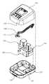
도 1은 본 발명이 적용된 기침 보조 장치가 도시된 사시도.
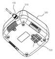
도 2는 본 발명이 적용된 기침 보조 장치가 도시된 요부의 분해 사시도.
도 3은 본 발명이 적용된 기침 보조 장치가 도시된 저면 사시도.
도 4는 본 발명이 적용된 기침 보조 장치의 공기압 발생 유닛과 방향 전환 밸브 유닛을 도시한 사시도.
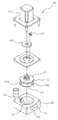
도 5는 본 발명이 적용된 방향 전환 밸브 유닛을 도시한 분해 사시도.
도 6은 본 발명이 적용된 방향 전환 밸브 유닛을 도시한 측단면도.
도 7은 본 발명이 적용된 방향 전환 밸브 유닛을 도시한 정단면도.
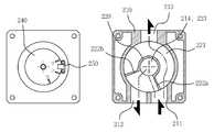
도 8은 본 발명이 적용된 방향 전환 밸브 유닛을 도시한 평단면도.
도 9는 본 발명이 적용된 방향 전환 밸브 유닛을 도시한 평면도.
도 10 내지 도 13은 본 발명이 적용된 방향 전환 밸브 유닛의 작동 상태를 도시한 설명도.
도 14는 본 발명이 적용된 기침 보조 장치가 도시한 저면 분해 사시도.
도 15은 본 발명이 적용된 기침 보조 장치의 공기 출입구 및 보조 연결구를 도시한 분해 사시도.
도 16은 본 발명이 적용된 연결구 및 보조 연결구의 결합 상태를 도시한 단면도.
도 17은 본 발명이 적용된 보조 연결구의 사용 예를 도시한 사용상태 사시도.1 is a perspective view showing a cough aid device to which the present invention is applied.
Figure 2 is an exploded perspective view of the main portion showing the cough aid device to which the present invention is applied.
Figure 3 is a bottom perspective view of the cough aid device to which the present invention is applied.
4 is a perspective view showing an air pressure generating unit and a directional valve unit of the cough assistance device to which the present invention is applied.
5 is an exploded perspective view showing a direction change valve unit to which the present invention is applied.
Figure 6 is a side cross-sectional view showing a directional valve unit to which the present invention is applied.
7 is a front sectional view showing a directional valve unit to which the present invention is applied.
8 is a plan sectional view showing a directional valve unit to which the present invention is applied.
Figure 9 is a plan view showing a directional valve unit to which the present invention is applied.
10 to 13 are explanatory diagrams showing an operating state of the direction change valve unit to which the present invention is applied.
Figure 14 is a bottom exploded perspective view showing a cough aid device to which the present invention is applied.
15 is an exploded perspective view showing an air inlet and an auxiliary connector of the cough aid device to which the present invention is applied.
Figure 16 is a cross-sectional view showing a coupling state of the connector and the auxiliary connector to which the present invention is applied.
Figure 17 is a perspective view showing the state of use of the auxiliary connector to which the present invention is applied.
본 발명의 바람직한 실시 예를 첨부된 도면에 의거하여 구체적으로 살펴본다.
Preferred embodiments of the present invention will now be described in detail with reference to the accompanying drawings.
본 발명의 기침 보조 장치는 도 1 내지 도 17에 도시된 바와 같이 공기압 발생 유닛(100)과 방향 전환 밸브 유닛(200)을 포함하여 구성된다.
As illustrated in FIGS. 1 to 17, the cough assist device of the present invention includes an air
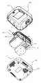
상기 공기압 발생 유닛(100)은 공기 흡입구(110)를 통해 공기를 흡입하면서 동시에 공기 배출구(120)를 통해 공기를 배출시키는 것으로서, 예를 들어 도 2 및 도 4에 도시된 바와 같이 모터의 회전력을 조절하여 터보 팬이 공기를 공급 또는 흡입하는 공기압을 조절한다. 상기 공기압 발생 유닛(100)의 공기압은 환자로 공급되는 공기를 강하게 또는 약하게 공급하거나 흡입하는 역할을 한다. 상기 공기압 발생 유닛(100)은 실시 예로서 터보 팬(Turbo fan)이 적용되기 때문에 회전 축 방향에 공기 흡입구(110)가 형성되고 측면에 공기 배출구(120)가 형성되며, 상기 공기 흡입구(110)와 공기 배출구(120)는 전방을 향해 연결되도록 한다.
The air
상기 방향 전환 밸브 유닛(200)은 상기 공기압 발생 유닛(100)으로부터 발생하는 공기압을 이용하여 호흡기관으로 공기를 공급하거나 호흡기관으로부터 공기를 흡입하도록 방향을 전환하는 것으로서, 상기 공기압에 의한 공기의 일부를 외부로 배출시키거나 외부로부터 공기를 일부 흡입하여 공기압을 조절하도록 형성된다. 즉, 본 발명의 방향 전환 밸브 유닛(200)이 공기를 공급하거나 흡입하는 역할 외에 공기를 공급 또는 흡입하는 과정에서 외부로 공기가 빠져나가거나 외부의 공기가 유입되도록 하여 공기압을 조절하는 기능이 포함된 것이다. 이 경우 외부로 빠져나가거나 외부로부터 유입되는 공기량이 많아지면 환자로 공급되거나 흡입되는 공기압이 작아지고, 외부로 빠져나가거나 외부로부터 유입되는 공기량이 작아지면 환자로 공급되거나 흡입되는 공기압이 작아진다.The direction
상기 방향 전환 밸브 유닛(200)의 실시 예로서 도 4 내지 도 13에 도시된 바와 같이 하우징(210), 회전체(220) 및 정역 모터(230)를 포함하여 구성된다.4 to 13, the
상기 하우징(210)은 전면에 공기가 출입하는 입구(211)와 출구(212)가 각각 형성되고, 배면에는 공기가 출입하는 제1 출입구(213)가 형성되며, 바닥면에는 공기가 출입하는 제2 출입구(214)가 형성된다. 상기 입구(211)와 출구(212)는 좌우에 나란하게 형성되고, 상기 제1 출입구(213)는 중앙에 형성되는데, 상기 입구(211)와 출구(212) 및 제1 출입구(213)는 동일한 높이에 형성되도록 한다. 상기 제2 출입구(214)는 내부의 중심 축 상에 형성된다.The
상기 회전체(220)는 상기 하우징(210) 내부에 축 설치되고, 둥근 외면을 따라 상기 입구(211)와 출구(212)로부터 상기 제1 출입구(213)로 이동하는 수평 통로(221)가 형성되며, 상기 수평 통로(221)의 일정 구간은 한 쌍의 격판(222a, 222b)으로 구획되고, 중심에는 상기 제2 출입구(214)로부터 상기 한 쌍의 격판(222a, 222b) 사이로 연결되는 수직 통로(223)가 형성된다. 이때, 상기 한 쌍의 격판(222a, 222b)은 그 사이에 상기 입구(211)와 출구(212)를 동시에 커버하도록 축으로부터 일정각도 벌어지게 형성된다. 따라서 상기 회전체(220)가 회전하여 상기 격판(222a, 222b)의 위치를 변경하기 때문에 입구(211)와 제1 출입구(213) 사이에 통로를 개방하거나 출구(212)와 제1 출입구(213) 사이의 통로를 개방하거나, 입구(211) 및 출구(212)와 제1 출입구(213) 사이의 통로를 차단하면서 제2 출입구(214)와 개방되도록 하는 한편, 상기 입구(211) 및 출구(212)와 제1 출입구(213) 또는 제2 출입구(214) 사이에 통로를 동시에 개방하도록 하는 것이다. 이에 대한 구체적인 작용은 아래에서 설명한다.The
상기 정역 모터(230)는 상기 하우징(210) 상측에 설치되고, 상기 회전체(220)의 축과 연결되는 것으로서, 상기 회전체(220)의 회전 각도를 조절하게 된다.The forward and
아울러, 상기 방향 전환 밸브 유닛(200)은 상기 회전체(220)의 회전을 감지하면서 정역 모터(230)의 구동을 제어하기 위한 감지수단을 포함하여 구성된다. 즉, 상기 감지수단은 현재 회전체(220)의 회전 각도를 감지하여 제1 출입구(213)를 통해 공급 또는 흡입되는 공기압이 어느 정도인지를 인식할 수 있고, 이로 인해 정확한 공기압을 조절할 수 있는 것이다. 상기 감지수단은 실시 예로서 상기 정역 모터(230)와 회전체(220) 사이의 축에 결합되고, 테두리를 따라 일정간격으로 마크가 형성된 원반(240)과 상기 하우징(210) 상측에 설치되고, 상기 원반(240)의 마크를 감지하는 센서(250)를 포함하여 구성된다. 상기 원반(240)의 마크는 센서가 감지할 수 있는 홀이 될 수 있고, 이 경우 상기 센서(250)는 광신호를 이용한 포토 센서가 될 수 있다.
In addition, the direction switching
본 발명의 기침 보조 장치는 실시 예로서 도 2 및 도 4에 도시된 바와 같이 상기 공기압 발생 유닛(100)의 공기 흡입구(110) 및 공기 배출구(120)와 상기 방향 전환 밸브 유닛(200)의 입구(211)와 출구(212)를 연결하면서 공기의 이동 통로를 형성하는 연결함(300)을 포함하여 구성된다. 즉, 기존에 관으로 연결되는 구성을 대체하여 단일화된 하나의 연결함(300)을 통해 공기압 발생 유닛(100)과 방향 전환 밸브 유닛(200) 사이의 공기 통로를 형성함으로써, 설치공간을 좀더 줄일 수 있는 것이다. 이를 위해 상기 공기압 발생 유닛(100)의 공기 흡입구(110) 및 공기 배출구(120)와 방향 전환 밸브 유닛(200)의 입구(211) 및 출구(212)는 동일한 방향으로 형성해야 한다.As shown in FIG. 2 and FIG. 4, the cough assist device of the present invention has an
상기 연결함(300)은 실시 예로서 밀폐된 내부에 상기 연결된 공기 배출구(120)와 입구(211)가 연결되는 제1 통로(310)와 상기 공기 흡입구(110)와 출구(212)를 연결하는 제2 통로(320)가 격벽에 의해 구획 형성된다. 따라서 상기 공기압 발생 유닛(100)의 공기 배출구(120)로부터 배출되는 공기는 방향 전환 밸브 유닛(200)의 입구(211)를 통해 환자의 호흡기관으로 공급하고, 상기 공기압 발생 유닛(100)의 공기 흡입구(110)에서 흡입하는 공기는 방향 전환 밸브 유닛(200)의 출구(212)를 통해 환자의 호흡기관으로부터 흡입하게 된다.
The
본 발명의 기침 보조 장치는 실시 예로서 도 2 및 도 3에 도시된 바와 같이 상기 방향 전환 밸브 유닛(200)의 제1 출입구(213)와 호스로 연결되고, 환자의 입에 밀착하기 위한 마스크 호스와 연결하도록 형성된 연결구(400)가 구성되고, 상기 공기압 발생 유닛(100), 방향 전환 밸브 유닛(200) 및 연결함(300)을 안착시킨 상태로 커버하도록 하되, 상기 연결구(400)가 관통하여 결합되는 결합구(510)와 상기 방향 전환 밸브 유닛(200)의 제2 출입구(214)에 대응하는 통풍구(520)가 형성된 케이스(500)가 구성된다.As shown in FIG. 2 and FIG. 3, the cough assist device of the present invention is connected to the
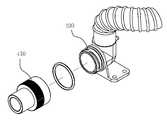
상기 연결구(400)는 실시 예로서 도 16 및 도 17에 도시된 바와 같이 보조 연결구(410)를 포함하여 구성된다. 상기 보조 연결구(410)은 상기 연결구(400)의 끝단에 결합되는 것으로서, 그 외면과 내면은 상기 연결구(400)의 외면 또는 내면과 다른 지름으로 형성된다. 즉, 상기 연결구(400)는 예를 들어 도 16에 도시된 바와 같이 내경의 지름(D1)이 22mm라면, 상기 보조 연결구(410)는 내경의 지름(D2)가 15mm이고, 외경의 지름(d1)이 22mm가 되도록 한다. 따라서 도 17에 도시된 바와 같이 상기 각각 다른 지름(D1, D2, d1)의 연결구에 대응하는 결합구가 형성된 마스크 호스, 박테리아 필터 또는 커넥터를 간편하게 연결하여 사용할 수 있게 된다.
The
이와 같은 구성으로 이루어진 기침 보조 장치의 작용을 구체적으로 살펴본다.Look at the action of the cough aid device made of such a configuration in detail.
작용의 구체적인 설명에 앞서 다음에 설명되는 용어를 정리하면 다음과 같다. 인헤일 모드(INHALE MODE)는 환자가 숨을 들이마시는 흡기상태이나, 본 발명의 기침 보조장치가 주체로서 공기압 발생 유닛(100)에서 발생한 공기압을 이용하여 연결함(300)과 방향 전환 밸브 유닛(200)을 통해 환자의 호흡기관으로 공기를 공급하는 상태로 설명한다. 퍼지 모드(PAUSE MODE)는 환자가 숨을 멈춘 무호흡상태이나, 본 발명의 기침 보조장치가 주체로서 공기압 발생 유닛(100)이 흡입하거나 배출하는 공기압을 방향 전환 밸브 유닛(200)이 차단하여 환자의 호흡기관으로 공기를 공급하거나 흡입하는 것을 멈춘 상태로 설명한다. 익스헤일 모드(EXHALE MODE)는 환자가 숨을 내뱉는 호기상태이나, 본 발명의 기침 보조장치가 주체로서 공기압 발생 유닛(100)에서 발생한 공기압을 이용하여 연결함(300)과 방향 전환 밸브 유닛(200)을 통해 환자의 호흡기관으로부터 공기를 흡입하는 상태로 설명한다. 이하, 이해를 돕기 위해 기침 보조장치를 통한 공급, 차단, 흡입과 함께 환자의 흡기, 호흡 멈춤 및 호기를 병행하여 표기한다.
Before describing the operation, the terms described below are summarized as follows. Inhale mode (INHALE MODE) is the inhalation state in which the patient inhales, but the cough aid of the present invention is connected mainly by using the air pressure generated in the air pressure generating unit 100 (300) and the directional valve unit ( It is described as a state supplying air to the respiratory tract of the patient through 200). PAUSE MODE is the apnea state in which the patient stops breathing, but the direction switching
이 경우 상기 공기압 발생 유닛(100)은 구동 속도를 조절하여 통상의 환자에게 적합한 공기압을 발생시켜 공기의 공급(환자는 흡기) 또는 흡입(환자는 호기)이 이루어지는 상태로서 설명하고, 상기 마스크 호스는 연결구(400) 또는 보조 연결구(410)에 연결한 후 환자의 입에 밀착시킨 상태로서 설명한다.
In this case, the air
최초 기침 보조 장치를 사용하기 위해 전원을 키고 압력을 설정한 상태에서 가동시키면 도 4에 도시된 바와 같이 상기 공기압 발생 유닛(100)이 설정된 압력에 따른 회전속도로 구동하면서 공기 흡입구(110)를 통해 공기를 흡입하고, 동시에 공기 배출구(120)를 통해 공기를 배출시킨다. 이때, 상기 공기 배출구(120)로부터 배출되는 공기는 연결함(300)의 제1 통로(310)를 통해 상기 방향 전환 밸브 유닛(200)의 입구(211)로 공급되고, 상기 공기 흡입구(110)로 흡입되는 공기는 상기 방향 전환 밸브 유닛(200)의 출구(212)로부터 상기 연결함(300)의 제2 통로(320)를 통해 흡입된다. 이와 같은 작용은 기침 보조 장치를 사용하는 동안 계속해서 변함없이 이루어진다. 다만, 기침 보조 장치의 사용 압력을 조절하면 상기 공기압 발생 유닛(100)의 구동속도가 변하면서 공기압이 조절된다.
When the power is turned on and the pressure is set to use the first cough assist device, the air
상기 인헤일 모드(INHALE MODE)는 도 10에 도시된 바와 같이 회전체(220)를 회전시켜 한 쌍의 격판(222a, 222b)을 통해 입구(211)와 제1 출입구(213)가 개방되도록 함으로써, 제1 출입구(213)를 통해 환자의 호흡기관으로 공기를 공급(환자는 흡기)한다. 이 경우 상기 제2 출입구(214)와 출구(212)가 개방되므로 외부의 신선한 공기가 공기압 발생 유닛(100)으로 흡입된다. 이때, 상기 감지수단에 의해 현재 환자의 호흡기관으로 설정된 압력의 공기를 공급(환자는 흡기)하고 있음을 인식하게 된다.In the HALE mode (INHALE MODE) by rotating the
이 과정에서 상기 환자의 호흡기관으로 공급(환자는 흡기)되는 공기압이 큰 경우 도 11에 도시된 바와 같이 회전체(220)를 일정각도 회전시켜 일측 격판(222a)이 입구(211) 사이에 위치하도록 함으로써, 일부의 공기가 제2 출입구(214) 또는 출구(212)로 빠져나가도록 하여 상기 제1 출입구(213)를 통해 환자의 호흡기관으로 공급(환자는 흡기)되는 공기의 압력을 조절한다. 이때, 상기 감지수단에 의해 회전체의 회전각도를 판단함으로써, 현재 얼마의 공기압으로 환자의 호흡기관에 공기를 공급(환자는 흡기)하고 있는지 알 수 있는데, 반대로 상기 감지수단에 의해 정확한 값으로 회전체를 회전시킬 수 있는 것이다.
In this process, when the air pressure supplied to the respiratory tract of the patient (patient is inhaled) is large, one
상기 퍼즈 모드(PAUSE MODE)는 도 12에 도시된 바와 같이 회전체(220)를 회전시켜 한 쌍의 격판(222a, 222b)을 통해 입구(211) 및 출구(212)가 제1 출입구(213)와 연결되는 통로를 막음으로써, 제1 출입구(213)를 통해 환자의 호흡기관으로 공급되는 공기를 차단(환자는 호흡 멈춤)하여 환자의 호흡이 멈추도록 한다. 이 경우 상기 입구(211) 및 출구(212)는 서로 개방된 상태이므로 자체적으로 공기를 순환시키고, 특히 입구(211) 및 출구(212)와 제2 출입구(214)가 개방된 상태이므로 내부의 공기가 외부로 배출되거나 외부의 신선한 공기가 공기압 발생 유닛(100)으로 흡입된다. 이때, 상기 감지수단에 의해 현재 환자의 호흡기관으로 공기의 공급이 차단(환자는 호흡 멈춤)되었음을 인식하게 된다.
In the PAUSE MODE, as shown in FIG. 12, the
상기 익스헤일 모드(EXHALE MODE)는 도 13에 도시된 바와 같이 회전체(220)를 회전시켜 한 쌍의 격판(222a, 222b)을 통해 출구(212)와 제1 출입구(213)가 개방되도록 함으로써, 제1 출입구(213)를 통해 환자의 호흡기관으로부터 공기를 흡입(환자는 호기)한다. 이 경우 상기 제2 출입구(214)와 입구(211)가 개방되므로 환자로부터 유입되는 내부의 공기가 공기압 발생 유닛(100)을 통해 외부로 배출된다. 이때, 상기 감지수단에 의해 현재 환자의 호흡기관으로부터 설정된 압력의 공기를 흡입(환자는 호기)하고 있음을 인식하게 된다.In the EXHALE MODE, as shown in FIG. 13, the
이때, 환자의 호흡기관으로부터 공기를 흡입(환자는 호기)하는 공기압은 공기압 발생 유닛(100)의 회전 속도를 통해서 조절한다. 즉, 초기에 환자의 상태를 확인하고 그에 따라 공기압 발생 유닛(100)의 회전 속도를 조절하여 공기를 흡입(환자는 호기)하는 공기압을 설정하되, 앞서 설명된 인헤일 모드와 같이 방향 전환 밸브 유닛(200)을 이용하여 흡입(환자는 호기)하는 공기압을 조절하지는 않는다. 이때, 상기 감지수단에 의해 회전체(220)의 회전각도를 판단함으로써, 현재 정상적으로 흡입(환자는 호기)이 이루어지고 있는 지를 확인할 수 있는 것이다.At this time, the air pressure for inhaling air (patient exhalation) from the respiratory tract of the patient is adjusted through the rotational speed of the air
이때, 상기 익스헤일 모드에서의 공기압 발생 유닛(100)의 회전 속도를 이용한 흡입(환자는 호기) 공기압력은 인헤일 모드에서의 공기압 발생 유닛(100)의 회전 속도를 이용한 공급(환자는 흡기) 공기압과 방향 전환 밸브 유닛(200)을 이용한 공급(환자는 흡기) 공기압을 합한 공기압 보다 크거나 같아야 한다. 즉, (익스헤일 모드의 공기압) ≥ (인헤일 모드의 공기압)의 공식이 성립되어야 하는데, 이는 환자로 공급한 공기가 완전히 흡입되지 못할 경우 환자의 호흡기관에 이물질이 완전히 빠지지 못하고 남아있을 수 있기 때문이다.
At this time, the suction (patient exhalation) using the rotational speed of the air
따라서 이와 같은 본 발명의 구성과 그로 인한 작용에 의하면 공기압 발생 유닛(100) 및 방향 전환 밸브 유닛(200)을 통해 환자에게 최적의 공기압으로 공기를 공급 또는 배출하도록 형성함으로써, 사용이 더욱 안전해지게 된다.Therefore, according to the configuration of the present invention and the effects thereof, the air
또한, 방향 전환 밸브 유닛(200)을 통해 공기가 외부로 배출되고 또 외부에서 새로운 공기가 유입됨으로써, 환자에게 신선한 공기를 공급할 수 있게 된다.In addition, the air is discharged to the outside through the
아울러, 연결구(400)에 결합하는 보조 연결구(410)를 통해 유아용이나 성인용 또는 여러 범용 마스크를 교체하여 사용할 수 있도록 함으로써, 사용이 더욱 편리해진다.
In addition, by allowing the
100: 공기압 발생 유닛 110: 공기 흡입구
120: 공기 배출구
200: 방향 전환 밸브 유닛 210: 하우징
211: 입구 212: 출구
213: 제1 출입구 214: 제2 출입구
220: 회전체 221: 수평통로
222: 격판 223: 수직통로
230: 정역 모터 240: 원반
250: 센서
300: 연결함 310: 제1 통로
320: 제2 통로
400: 연결구 410: 보조 연결구
500: 케이스 510: 결합구
520: 통풍구100: air pressure generating unit 110: air intake
120: air outlet
200: direction change valve unit 210: housing
211: entrance 212: exit
213: first doorway 214: second doorway
220: rotating body 221: horizontal passage
222: plate 223: vertical passage
230: static motor 240: disc
250: sensor
300: connected box 310: first passage
320: second passage
400: connector 410: auxiliary connector
500: case 510: coupler
520: vent
Claims (13)
Translated fromKorean상기 하우징 내부에 축 설치되고, 둥근 외면을 따라 상기 입구와 출구로부터 상기 제1 출입구로 이동하는 수평 통로가 형성되며, 상기 수평 통로의 일정 구간은 한 쌍의 격판으로 구획되고, 중심에는 상기 제2 출입구로부터 상기 한 쌍의 격판 사이로 연결되는 수직 통로가 형성된 회전체; 및
상기 하우징 상측에 설치되고, 상기 회전체의 축과 연결되는 정역 모터;를 포함하여 구성된 것을 특징으로 하는 방향 전환 밸브 유닛.
A housing having an inlet and an outlet through which air enters and exits, a first entrance through which air enters and a rear, respectively, and a second entrance through which air enters and exits;
A shaft is installed inside the housing, and a horizontal passage is formed to move from the inlet and the outlet to the first entrance along a rounded outer surface, and a predetermined section of the horizontal passage is partitioned by a pair of diaphragms, and in the center of the second passage. A rotating body having a vertical passage connected from the entrance to the pair of diaphragms; And
And a forward and reverse motor installed at the upper side of the housing and connected to the shaft of the rotating body.
The directional valve unit according to claim 1, wherein the pair of diaphragms are formed at an angle from the shaft to simultaneously cover the inlet and the outlet therebetween.
The directional valve unit of claim 1, comprising sensing means for controlling the driving of the motor while sensing the rotation of the rotating body.
상기 정역 모터와 회전체 사이의 축에 결합되고, 테두리를 따라 일정간격으로 마크가 형성된 원반; 및
상기 하우징 상측에 설치되고, 상기 원반의 마크를 감지하는 센서;를 포함하여 구성된 것을 특징으로 하는 방향 전환 밸브 유닛.
The method according to claim 3, The sensing means,
A disk coupled to an axis between the stationary motor and the rotating body and having marks formed at regular intervals along an edge thereof; And
And a sensor installed above the housing and sensing a mark of the disc.
상기 공기압 발생 유닛으로부터 발생하는 공기압을 이용하여 호흡기관으로 공기를 공급하거나 호흡기관으로부터 공기를 흡입하도록 방향을 전환하도록 하되, 상기 공기압에 의한 공기의 일부를 외부로 배출시키거나 외부로부터 공기를 일부 흡입하여 공기압을 조절하도록 형성된 방향 전환 밸브 유닛;을 포함하여 구성된 것을 특징으로 하는 기침 보조 장치.
An air pressure generating unit that sucks air through the air inlet and simultaneously exhausts air through the air outlet; And
The air pressure generated from the air pressure generating unit is used to change the direction to supply air to the respiratory tract or to suck air from the respiratory tract, and to discharge a part of the air by the pneumatic pressure to the outside or to suck some air from the outside. Cough assistance device comprising a; direction change valve unit formed to adjust the air pressure.
전면에는 공기가 출입하는 입구와 출구가 각각 형성되고, 배면에는 공기가 출입하는 제1 출입구가 형성되며, 바닥면에는 공기가 출입하는 제2 출입구가 형성된 하우징;
상기 하우징 내부에 축 설치되고, 둥근 외면을 따라 상기 입구와 출구로부터 상기 제1 출입구로 이동하는 수평 통로가 형성되며, 상기 수평 통로의 일정 구간은 한 쌍의 격판으로 구획되고, 중심에는 상기 제2 출입구로부터 상기 한 쌍의 격판 사이로 연결되는 수직 통로가 형성된 회전체; 및
상기 하우징 상측에 설치되고, 상기 회전체의 축과 연결되는 정역 모터;를 포함하여 구성된 것을 특징으로 하는 기침 보조 장치.
The method according to claim 5, The direction switching valve unit,
A housing having an inlet and an outlet through which air enters and exits, a first entrance through which air enters and a rear, respectively, and a second entrance through which air enters and exits;
A shaft is installed inside the housing, and a horizontal passage is formed to move from the inlet and the outlet to the first entrance along a rounded outer surface, and a predetermined section of the horizontal passage is partitioned by a pair of diaphragms, and in the center of the second passage. A rotating body having a vertical passage connected from the entrance to the pair of diaphragms; And
And a forward and reverse motor installed on the housing and connected to the shaft of the rotating body.
The cough assisting device according to claim 6, wherein the pair of diaphragms are formed at an angle from the shaft to simultaneously cover the inlet and the outlet therebetween.
The cough aid device according to claim 6, comprising a sensing means for controlling the driving of the motor while sensing the rotation of the rotating body.
상기 정역 모터와 회전체 사이의 축에 결합되고, 테두리를 따라 일정간격으로 마크가 형성된 원반; 및
상기 하우징 상측에 설치되고, 상기 원반의 마크를 감지하는 센서;를 포함하여 구성된 것을 특징으로 하는 기침 보조 장치.
The method according to claim 8, The sensing means,
A disk coupled to an axis between the stationary motor and the rotating body and having marks formed at regular intervals along an edge thereof; And
And a sensor installed on the housing and detecting a mark of the disc.
The cough assisting device according to claim 6, wherein the air inlet and the air outlet of the air pressure generating unit and the inlet and the outlet of the directional valve unit are connected to form an air passage.
The cough assisting device according to claim 10, wherein the junction box is formed in a sealed interior, the first passage connecting the connected air outlet and the inlet and the second passage connecting the air inlet and the outlet.
상기 공기압 발생 유닛, 방향 전환 밸브 유닛 및 연결함을 안착시킨 상태로 커버하도록 하되, 상기 연결구가 관통하여 결합되는 결합구와 상기 방향 전환 밸브 유닛의 제2 출입구에 대응하는 통풍구가 형성된 케이스;를 포함하여 구성된 것을 특징으로 하는 기침 보조 장치.
11. The apparatus of claim 10, further comprising: a connector connected to a first entrance of the directional valve unit by a hose, the connector being connected to a mask hose to closely contact a patient's mouth; And
A case formed to cover the air pressure generating unit, the direction switching valve unit, and the connection box in a seated state, wherein a coupling port through which the connector is coupled and a ventilation hole corresponding to the second entrance of the direction switching valve unit is formed; Cough aid device, characterized in that configured.
The cough assisting device according to claim 12, wherein the auxiliary connector is coupled to an end of the connector, and the outer and inner surfaces thereof are auxiliary connectors formed to have different diameters from the outer surface or the inner surface of the connector.
Priority Applications (1)
| Application Number | Priority Date | Filing Date | Title |
|---|---|---|---|
| KR1020110011994AKR101038262B1 (en) | 2011-02-10 | 2011-02-10 | Directional valve unit and cough aid |
Applications Claiming Priority (1)
| Application Number | Priority Date | Filing Date | Title |
|---|---|---|---|
| KR1020110011994AKR101038262B1 (en) | 2011-02-10 | 2011-02-10 | Directional valve unit and cough aid |
Publications (1)
| Publication Number | Publication Date |
|---|---|
| KR101038262B1true KR101038262B1 (en) | 2011-06-01 |
Family
ID=44404848
Family Applications (1)
| Application Number | Title | Priority Date | Filing Date |
|---|---|---|---|
| KR1020110011994AExpired - Fee RelatedKR101038262B1 (en) | 2011-02-10 | 2011-02-10 | Directional valve unit and cough aid |
Country Status (1)
| Country | Link |
|---|---|
| KR (1) | KR101038262B1 (en) |
Cited By (11)
| Publication number | Priority date | Publication date | Assignee | Title |
|---|---|---|---|---|
| KR101160880B1 (en) | 2012-03-27 | 2012-06-28 | (주)서일퍼시픽 | Regulating device of aerial inflow volume |
| KR101180309B1 (en)* | 2012-03-27 | 2012-09-06 | (주)서일퍼시픽 | Direction change valve module and Cough assistance machine using the direction change valve module |
| KR101192689B1 (en)* | 2012-03-27 | 2012-10-19 | (주)서일퍼시픽 | Device of cough help |
| KR101459332B1 (en)* | 2014-08-19 | 2014-11-07 | (주)서일퍼시픽 | Portable cough stimulating device using high frequency vibration wave |
| KR101606681B1 (en)* | 2016-01-13 | 2016-03-28 | (주)서일퍼시픽 | Portable cough stimulating device |
| KR20210047409A (en)* | 2019-10-21 | 2021-04-30 | 인제대학교 산학협력단 | Device of self pulmonary rehabilitation |
| CN113117210A (en)* | 2021-04-17 | 2021-07-16 | 赵田田 | A supplementary respiratory equipment for infectious department |
| KR20220090170A (en)* | 2020-12-22 | 2022-06-29 | 연세대학교 산학협력단 | The device assisting lung expansion and coughing for the patients in a state of uncontrollable glottis function, apparatus and method including the same |
| KR20230015220A (en) | 2021-07-22 | 2023-01-31 | 주식회사 쉐어앤서비스 | Cough causing apparatus and Switching valve device for the same |
| CN116672555A (en)* | 2022-01-18 | 2023-09-01 | 河北金康安医疗器械科技有限公司 | Gas path switching device and expectoration system of expectoration machine |
| KR20240068476A (en) | 2022-11-10 | 2024-05-17 | 주식회사 쉐어앤서비스 | Switching valve device for cough causing apparatus and cough causing apparatus using the same |
Citations (4)
| Publication number | Priority date | Publication date | Assignee | Title |
|---|---|---|---|---|
| JPH1043288A (en) | 1986-05-15 | 1998-02-17 | C R Bard Inc | Suction drainage device |
| JP2002511786A (en) | 1998-03-17 | 2002-04-16 | レスメッド・リミテッド | Breathable gas supply |
| KR20040097437A (en)* | 2003-05-12 | 2004-11-18 | 비앤알(주) | Medical bottle |
| KR20100129770A (en)* | 2008-03-17 | 2010-12-09 | 디스커버리 라보라토리스, 인크. | Breathing Circuit Adapters and Proximal Aerosol Delivery Systems |
- 2011
- 2011-02-10KRKR1020110011994Apatent/KR101038262B1/ennot_activeExpired - Fee Related
Patent Citations (4)
| Publication number | Priority date | Publication date | Assignee | Title |
|---|---|---|---|---|
| JPH1043288A (en) | 1986-05-15 | 1998-02-17 | C R Bard Inc | Suction drainage device |
| JP2002511786A (en) | 1998-03-17 | 2002-04-16 | レスメッド・リミテッド | Breathable gas supply |
| KR20040097437A (en)* | 2003-05-12 | 2004-11-18 | 비앤알(주) | Medical bottle |
| KR20100129770A (en)* | 2008-03-17 | 2010-12-09 | 디스커버리 라보라토리스, 인크. | Breathing Circuit Adapters and Proximal Aerosol Delivery Systems |
Cited By (17)
| Publication number | Priority date | Publication date | Assignee | Title |
|---|---|---|---|---|
| US9345851B2 (en) | 2012-03-27 | 2016-05-24 | Seoil Pacific Corp | Direction switching valve unit and cough assisting device using the same |
| KR101180309B1 (en)* | 2012-03-27 | 2012-09-06 | (주)서일퍼시픽 | Direction change valve module and Cough assistance machine using the direction change valve module |
| KR101192689B1 (en)* | 2012-03-27 | 2012-10-19 | (주)서일퍼시픽 | Device of cough help |
| KR101160880B1 (en) | 2012-03-27 | 2012-06-28 | (주)서일퍼시픽 | Regulating device of aerial inflow volume |
| KR101459332B1 (en)* | 2014-08-19 | 2014-11-07 | (주)서일퍼시픽 | Portable cough stimulating device using high frequency vibration wave |
| CN106964038B (en)* | 2016-01-13 | 2019-09-03 | 株式会社瑞日太平洋 | Movable type cough inducer |
| WO2017122910A1 (en)* | 2016-01-13 | 2017-07-20 | (주)서일퍼시픽 | Portable in-exsufflator |
| CN106964038A (en)* | 2016-01-13 | 2017-07-21 | 株式会社瑞日太平洋 | Movable type cough inducer |
| KR101606681B1 (en)* | 2016-01-13 | 2016-03-28 | (주)서일퍼시픽 | Portable cough stimulating device |
| KR20210047409A (en)* | 2019-10-21 | 2021-04-30 | 인제대학교 산학협력단 | Device of self pulmonary rehabilitation |
| KR102300819B1 (en) | 2019-10-21 | 2021-09-14 | 인제대학교 산학협력단 | Device of self pulmonary rehabilitation |
| KR20220090170A (en)* | 2020-12-22 | 2022-06-29 | 연세대학교 산학협력단 | The device assisting lung expansion and coughing for the patients in a state of uncontrollable glottis function, apparatus and method including the same |
| KR102565104B1 (en) | 2020-12-22 | 2023-08-09 | 연세대학교 산학협력단 | The device assisting lung expansion and coughing for the patients in a state of uncontrollable glottis function, apparatus and method including the same |
| CN113117210A (en)* | 2021-04-17 | 2021-07-16 | 赵田田 | A supplementary respiratory equipment for infectious department |
| KR20230015220A (en) | 2021-07-22 | 2023-01-31 | 주식회사 쉐어앤서비스 | Cough causing apparatus and Switching valve device for the same |
| CN116672555A (en)* | 2022-01-18 | 2023-09-01 | 河北金康安医疗器械科技有限公司 | Gas path switching device and expectoration system of expectoration machine |
| KR20240068476A (en) | 2022-11-10 | 2024-05-17 | 주식회사 쉐어앤서비스 | Switching valve device for cough causing apparatus and cough causing apparatus using the same |
Similar Documents
| Publication | Publication Date | Title |
|---|---|---|
| KR101038262B1 (en) | Directional valve unit and cough aid | |
| US9345851B2 (en) | Direction switching valve unit and cough assisting device using the same | |
| CN101628134B (en) | Respiration device | |
| JP2022020679A (en) | Ventilator devices and methods | |
| CN112169130B (en) | Breathable gas inlet control apparatus for respiratory therapy device | |
| AU2016339393B2 (en) | Inexsufflation system | |
| BRPI0716568A2 (en) | METHOD FOR OPERATING A PATIENT FAN ASSEMBLY, AND PATIENT FAN APPLIANCE | |
| CN106110457B (en) | A kind of sputum elimination machine and its respirator system | |
| CN208340024U (en) | A kind of novel Respiratory Medicine lung capacity training device | |
| CN107096104A (en) | A kind of Oxygen therapy apparatus and its nasal tube road | |
| AU2008319519A1 (en) | Fan unit with bypass vent holes | |
| KR101459332B1 (en) | Portable cough stimulating device using high frequency vibration wave | |
| KR101606681B1 (en) | Portable cough stimulating device | |
| JP2019195646A (en) | Ventilator apparatus and method | |
| CN117563159B (en) | Following type auxiliary air supply respirator and control method thereof | |
| CN201727823U (en) | Double-air-passage laryngeal mask | |
| JP2002219175A (en) | Adapter for artificial respiration suctioning and automatic suctioning device | |
| CN206120951U (en) | Sputum excretion machine and diaphragm valve thereof | |
| KR101192689B1 (en) | Device of cough help | |
| KR101160880B1 (en) | Regulating device of aerial inflow volume | |
| TWM605814U (en) | Auxiliary device for breathing | |
| CN216319373U (en) | Mask for preventing backflow and aspiration in anesthesia induction process | |
| CN212491074U (en) | Epidemic prevention breathing machine with sleep apnea prevention function | |
| CN210020725U (en) | Expectoration qi invigorating device | |
| KR20240068476A (en) | Switching valve device for cough causing apparatus and cough causing apparatus using the same |
Legal Events
| Date | Code | Title | Description |
|---|---|---|---|
| A201 | Request for examination | ||
| PA0109 | Patent application | St.27 status event code:A-0-1-A10-A12-nap-PA0109 | |
| PA0201 | Request for examination | St.27 status event code:A-1-2-D10-D11-exm-PA0201 | |
| P11-X000 | Amendment of application requested | St.27 status event code:A-2-2-P10-P11-nap-X000 | |
| R15-X000 | Change to inventor requested | St.27 status event code:A-3-3-R10-R15-oth-X000 | |
| A302 | Request for accelerated examination | ||
| PA0302 | Request for accelerated examination | St.27 status event code:A-1-2-D10-D17-exm-PA0302 St.27 status event code:A-1-2-D10-D16-exm-PA0302 | |
| P11-X000 | Amendment of application requested | St.27 status event code:A-2-2-P10-P11-nap-X000 | |
| P13-X000 | Application amended | St.27 status event code:A-2-2-P10-P13-nap-X000 | |
| PE0801 | Dismissal of amendment | St.27 status event code:A-2-2-P10-P12-nap-PE0801 | |
| R15-X000 | Change to inventor requested | St.27 status event code:A-3-3-R10-R15-oth-X000 | |
| R16-X000 | Change to inventor recorded | St.27 status event code:A-3-3-R10-R16-oth-X000 | |
| E902 | Notification of reason for refusal | ||
| PE0902 | Notice of grounds for rejection | St.27 status event code:A-1-2-D10-D21-exm-PE0902 | |
| P11-X000 | Amendment of application requested | St.27 status event code:A-2-2-P10-P11-nap-X000 | |
| P13-X000 | Application amended | St.27 status event code:A-2-2-P10-P13-nap-X000 | |
| E701 | Decision to grant or registration of patent right | ||
| PE0701 | Decision of registration | St.27 status event code:A-1-2-D10-D22-exm-PE0701 | |
| GRNT | Written decision to grant | ||
| PR0701 | Registration of establishment | St.27 status event code:A-2-4-F10-F11-exm-PR0701 | |
| PR1002 | Payment of registration fee | St.27 status event code:A-2-2-U10-U11-oth-PR1002 Fee payment year number:1 | |
| PG1601 | Publication of registration | St.27 status event code:A-4-4-Q10-Q13-nap-PG1601 | |
| FPAY | Annual fee payment | Payment date:20140218 Year of fee payment:4 | |
| PR1001 | Payment of annual fee | St.27 status event code:A-4-4-U10-U11-oth-PR1001 Fee payment year number:4 | |
| FPAY | Annual fee payment | Payment date:20150313 Year of fee payment:5 | |
| PR1001 | Payment of annual fee | St.27 status event code:A-4-4-U10-U11-oth-PR1001 Fee payment year number:5 | |
| FPAY | Annual fee payment | Payment date:20160520 Year of fee payment:6 | |
| PR1001 | Payment of annual fee | St.27 status event code:A-4-4-U10-U11-oth-PR1001 Fee payment year number:6 | |
| P22-X000 | Classification modified | St.27 status event code:A-4-4-P10-P22-nap-X000 | |
| FPAY | Annual fee payment | Payment date:20170523 Year of fee payment:7 | |
| PR1001 | Payment of annual fee | St.27 status event code:A-4-4-U10-U11-oth-PR1001 Fee payment year number:7 | |
| PR1001 | Payment of annual fee | St.27 status event code:A-4-4-U10-U11-oth-PR1001 Fee payment year number:8 | |
| LAPS | Lapse due to unpaid annual fee | ||
| PC1903 | Unpaid annual fee | St.27 status event code:A-4-4-U10-U13-oth-PC1903 Not in force date:20190526 Payment event data comment text:Termination Category : DEFAULT_OF_REGISTRATION_FEE | |
| PC1903 | Unpaid annual fee | St.27 status event code:N-4-6-H10-H13-oth-PC1903 Ip right cessation event data comment text:Termination Category : DEFAULT_OF_REGISTRATION_FEE Not in force date:20190526 | |
| PN2301 | Change of applicant | St.27 status event code:A-5-5-R10-R13-asn-PN2301 St.27 status event code:A-5-5-R10-R11-asn-PN2301 |