KR101038203B1 - Package of wiper blade - Google Patents
Package of wiper bladeDownload PDFInfo
- Publication number
- KR101038203B1 KR101038203B1KR1020090050371AKR20090050371AKR101038203B1KR 101038203 B1KR101038203 B1KR 101038203B1KR 1020090050371 AKR1020090050371 AKR 1020090050371AKR 20090050371 AKR20090050371 AKR 20090050371AKR 101038203 B1KR101038203 B1KR 101038203B1
- Authority
- KR
- South Korea
- Prior art keywords
- wiper blade
- frame
- protrusion
- packaging container
- lower case
- Prior art date
- Legal status (The legal status is an assumption and is not a legal conclusion. Google has not performed a legal analysis and makes no representation as to the accuracy of the status listed.)
- Expired - Fee Related
Links
Images


Classifications
- B—PERFORMING OPERATIONS; TRANSPORTING
- B65—CONVEYING; PACKING; STORING; HANDLING THIN OR FILAMENTARY MATERIAL
- B65D—CONTAINERS FOR STORAGE OR TRANSPORT OF ARTICLES OR MATERIALS, e.g. BAGS, BARRELS, BOTTLES, BOXES, CANS, CARTONS, CRATES, DRUMS, JARS, TANKS, HOPPERS, FORWARDING CONTAINERS; ACCESSORIES, CLOSURES, OR FITTINGS THEREFOR; PACKAGING ELEMENTS; PACKAGES
- B65D85/00—Containers, packaging elements or packages, specially adapted for particular articles or materials
- B65D85/68—Containers, packaging elements or packages, specially adapted for particular articles or materials for machines, engines or vehicles in assembled or dismantled form
- B—PERFORMING OPERATIONS; TRANSPORTING
- B65—CONVEYING; PACKING; STORING; HANDLING THIN OR FILAMENTARY MATERIAL
- B65D—CONTAINERS FOR STORAGE OR TRANSPORT OF ARTICLES OR MATERIALS, e.g. BAGS, BARRELS, BOTTLES, BOXES, CANS, CARTONS, CRATES, DRUMS, JARS, TANKS, HOPPERS, FORWARDING CONTAINERS; ACCESSORIES, CLOSURES, OR FITTINGS THEREFOR; PACKAGING ELEMENTS; PACKAGES
- B65D75/00—Packages comprising articles or materials partially or wholly enclosed in strips, sheets, blanks, tubes or webs of flexible sheet material, e.g. in folded wrappers
- B65D75/04—Articles or materials wholly enclosed in single sheets or wrapper blanks
- B65D75/20—Articles or materials wholly enclosed in single sheets or wrapper blanks in sheets or blanks doubled around contents and having their opposed free margins united, e.g. by pressure-sensitive adhesive, crimping, heat-sealing, or welding
- B65D75/22—Articles or materials wholly enclosed in single sheets or wrapper blanks in sheets or blanks doubled around contents and having their opposed free margins united, e.g. by pressure-sensitive adhesive, crimping, heat-sealing, or welding the sheet or blank being recessed to accommodate contents
- B—PERFORMING OPERATIONS; TRANSPORTING
- B65—CONVEYING; PACKING; STORING; HANDLING THIN OR FILAMENTARY MATERIAL
- B65D—CONTAINERS FOR STORAGE OR TRANSPORT OF ARTICLES OR MATERIALS, e.g. BAGS, BARRELS, BOTTLES, BOXES, CANS, CARTONS, CRATES, DRUMS, JARS, TANKS, HOPPERS, FORWARDING CONTAINERS; ACCESSORIES, CLOSURES, OR FITTINGS THEREFOR; PACKAGING ELEMENTS; PACKAGES
- B65D43/00—Lids or covers for rigid or semi-rigid containers
- B65D43/14—Non-removable lids or covers
- B65D43/16—Non-removable lids or covers hinged for upward or downward movement
- B65D43/162—Non-removable lids or covers hinged for upward or downward movement the container, the lid and the hinge being made of one piece
- B—PERFORMING OPERATIONS; TRANSPORTING
- B65—CONVEYING; PACKING; STORING; HANDLING THIN OR FILAMENTARY MATERIAL
- B65D—CONTAINERS FOR STORAGE OR TRANSPORT OF ARTICLES OR MATERIALS, e.g. BAGS, BARRELS, BOTTLES, BOXES, CANS, CARTONS, CRATES, DRUMS, JARS, TANKS, HOPPERS, FORWARDING CONTAINERS; ACCESSORIES, CLOSURES, OR FITTINGS THEREFOR; PACKAGING ELEMENTS; PACKAGES
- B65D75/00—Packages comprising articles or materials partially or wholly enclosed in strips, sheets, blanks, tubes or webs of flexible sheet material, e.g. in folded wrappers
- B65D75/28—Articles or materials wholly enclosed in composite wrappers, i.e. wrappers formed by associating or interconnecting two or more sheets or blanks
- B65D75/30—Articles or materials enclosed between two opposed sheets or blanks having their margins united, e.g. by pressure-sensitive adhesive, crimping, heat-sealing, or welding
- B65D75/32—Articles or materials enclosed between two opposed sheets or blanks having their margins united, e.g. by pressure-sensitive adhesive, crimping, heat-sealing, or welding one or both sheets or blanks being recessed to accommodate contents
- B65D75/36—Articles or materials enclosed between two opposed sheets or blanks having their margins united, e.g. by pressure-sensitive adhesive, crimping, heat-sealing, or welding one or both sheets or blanks being recessed to accommodate contents one sheet or blank being recessed and the other formed of relatively stiff flat sheet material, e.g. blister packages, the recess or recesses being preformed
- B—PERFORMING OPERATIONS; TRANSPORTING
- B60—VEHICLES IN GENERAL
- B60S—SERVICING, CLEANING, REPAIRING, SUPPORTING, LIFTING, OR MANOEUVRING OF VEHICLES, NOT OTHERWISE PROVIDED FOR
- B60S1/00—Cleaning of vehicles
- B60S1/02—Cleaning windscreens, windows or optical devices
- B60S1/04—Wipers or the like, e.g. scrapers
- B60S1/32—Wipers or the like, e.g. scrapers characterised by constructional features of wiper blade arms or blades
- B60S1/38—Wiper blades
- B60S2001/3898—Wiper blades method for manufacturing wiper blades
- B—PERFORMING OPERATIONS; TRANSPORTING
- B65—CONVEYING; PACKING; STORING; HANDLING THIN OR FILAMENTARY MATERIAL
- B65D—CONTAINERS FOR STORAGE OR TRANSPORT OF ARTICLES OR MATERIALS, e.g. BAGS, BARRELS, BOTTLES, BOXES, CANS, CARTONS, CRATES, DRUMS, JARS, TANKS, HOPPERS, FORWARDING CONTAINERS; ACCESSORIES, CLOSURES, OR FITTINGS THEREFOR; PACKAGING ELEMENTS; PACKAGES
- B65D2585/00—Containers, packaging elements or packages specially adapted for particular articles or materials
- B65D2585/68—Containers, packaging elements or packages specially adapted for particular articles or materials for machines, engines, or vehicles in assembled or dismantled form
- B65D2585/6802—Containers, packaging elements or packages specially adapted for particular articles or materials for machines, engines, or vehicles in assembled or dismantled form specific machines, engines or vehicles
- B65D2585/6875—Containers, packaging elements or packages specially adapted for particular articles or materials for machines, engines, or vehicles in assembled or dismantled form specific machines, engines or vehicles engines, motors, machines and vehicle parts
- B65D2585/6882—Containers, packaging elements or packages specially adapted for particular articles or materials for machines, engines, or vehicles in assembled or dismantled form specific machines, engines or vehicles engines, motors, machines and vehicle parts vehicle parts
- B65D2585/6885—Containers, packaging elements or packages specially adapted for particular articles or materials for machines, engines, or vehicles in assembled or dismantled form specific machines, engines or vehicles engines, motors, machines and vehicle parts vehicle parts wiper blades
- Y—GENERAL TAGGING OF NEW TECHNOLOGICAL DEVELOPMENTS; GENERAL TAGGING OF CROSS-SECTIONAL TECHNOLOGIES SPANNING OVER SEVERAL SECTIONS OF THE IPC; TECHNICAL SUBJECTS COVERED BY FORMER USPC CROSS-REFERENCE ART COLLECTIONS [XRACs] AND DIGESTS
- Y10—TECHNICAL SUBJECTS COVERED BY FORMER USPC
- Y10S—TECHNICAL SUBJECTS COVERED BY FORMER USPC CROSS-REFERENCE ART COLLECTIONS [XRACs] AND DIGESTS
- Y10S206/00—Special receptacle or package
- Y10S206/825—Recoil-type retainer
Landscapes
- Engineering & Computer Science (AREA)
- Mechanical Engineering (AREA)
- Chemical & Material Sciences (AREA)
- Composite Materials (AREA)
- Packaging Of Annular Or Rod-Shaped Articles, Wearing Apparel, Cassettes, Or The Like (AREA)
- Packaging Of Machine Parts And Wound Products (AREA)
- Packages (AREA)
Abstract
Translated fromKoreanDescription
Translated fromKorean본 발명은 와이퍼 블레이드를 포장하기 위한 포장용기에 관한 것으로서, 더욱 상세하게는 포장된 와이퍼 블레이드가 용기의 내부에 형성된 고정수단에 의해 고정된 상태를 유지하여 제품의 손상을 방지할 수 있는 동시에 부피를 최소화하고 그 형상을 대용량 포장에 적합하도록 한 와이퍼 블레이드의 포장용기에 관한 것이다.The present invention relates to a packaging container for wrapping a wiper blade, and more particularly, the packaged wiper blade can be fixed by the fixing means formed in the interior of the container to prevent damage to the product and at the same time The present invention relates to a packaging container for wiper blades, which minimizes its shape and makes it suitable for large-capacity packaging.
일반적으로 자동차는 대기 중의 먼지 또는 기상상태에 따라 전방 유리면이 오염됨에 따라 시야가 흐려지는 것을 방지하기 위해, 전방 유리면을 닦는 와이퍼 블레이드가 설치된다. 상기 와이퍼 블레이드는 유리면과 밀착된 상태로 소정각도로 회동하면서 전방 유리면을 닦아 안전운전을 위한 운전자의 시계를 확보할 수 있다.In general, a vehicle is provided with a wiper blade for wiping the front glass surface in order to prevent blurred vision due to contamination of the front glass surface due to dust or weather conditions in the air. The wiper blade may be secured to the driver's watch for safe driving by wiping the front glass surface while rotating at a predetermined angle in close contact with the glass surface.
전술된 와이퍼 블레이드는 지속적인 사용에 의해 고무 스트립 부분이 열화되어 밀착 또는 세척력이 저하될 경우, 주기적 또는 비주기적으로 교체해야 할 필요가 있다. 따라서, 이러한 와이퍼 블레이드는 별도로 판매되고 있으며, 사용자는 판매되고 있는 와이퍼 블레이드 중에서 자신의 차량에 적합한 와이퍼 블레이드를 구매하여 직접 교체 사용하고 있다.The wiper blade described above needs to be replaced periodically or aperiodically when the rubber strip portion is degraded by continuous use and the adhesion or cleaning power is degraded. Therefore, these wiper blades are sold separately, and the user purchases a wiper blade suitable for his vehicle and directly replaces the wiper blade on the market.
한편, 자동차의 전방 유리면은 곡면으로 이루어져 있으며 와이퍼 블레이드는 이 전방 유리면에 밀착된 상태를 유지해야 하므로, 와이퍼 블레이드 역시 만곡된 형상을 가지도록 만들어질 필요가 있다.On the other hand, the front glass surface of the vehicle is made of a curved surface and the wiper blade should be kept in close contact with the front glass surface, so the wiper blade needs to be made to have a curved shape.
그런데, 만곡된 와이퍼 블레이드의 형상에 맞춰 만곡된 포장용기를 제작할 경우에는, 와이퍼 블레이드에 지나친 외력이 가해지지 않아 제품 보호가 용이하지만, 포장용기의 부피가 커지고 복수의 포장용기를 대형의 포장박스에 재포장할 때 포장공간을 많이 차지해 운반 및 유통비용이 과다하게 소모되는 문제가 있다.By the way, when manufacturing a curved packaging container according to the shape of the curved wiper blade, it is easy to protect the product because excessive external force is not applied to the wiper blade, but the volume of the packaging container is large and a plurality of packaging containers are placed in a large packaging box. When repacking takes up a lot of packaging space, there is a problem that excessive transportation and distribution costs are consumed.
이러한 문제를 해소하고자 직사각형(즉, 장방형)의 포장용기를 사용할 경우에는, 포장용기의 부피를 최소화할 수 있어 운반 및 유통비용을 절감할 수는 있지만, 만곡된 형상을 유지하려는 와이퍼 블레이드의 탄성으로 인하여 와이퍼 블레이드의 양쪽 말단의 고무 스트립 부분이 포장용기의 내부표면에 맞닿아 가압되면서 제품이 손상될 우려가 있다.In order to solve this problem, a rectangular (ie, rectangular) container is used, the volume of the container can be minimized to reduce the transportation and distribution costs, but the elasticity of the wiper blades to maintain the curved shape Due to this, the rubber strip portions at both ends of the wiper blade are pressed against the inner surface of the packaging container, which may damage the product.
이러한 종래의 문제점들을 해결하기 위한 본 발명은, 포장된 와이퍼 블레이드가 용기의 내부에 형성된 고정수단에 의해 고정된 상태를 유지할 수 있도록 함으로써 제품의 손상을 방지할 수 있는 동시에 부피를 최소화하고 그 형상을 대용량 포장에 적합하도록 한 와이퍼 블레이드의 포장용기를 제공하고자 하는 것이다.The present invention for solving the above problems, the packaged wiper blade can be kept fixed by the fixing means formed in the interior of the container to prevent damage to the product while minimizing the volume and shape It is an object of the present invention to provide a wiper blade packaging container suitable for high-capacity packaging.
상기 목적을 달성하기 위한 본 발명에 따르면, 자동차에 장착되어 사용될 때에는 원호형상으로 만곡된 형상을 가지도록 만들어지는 와이퍼 블레이드를 포장하기 위한 포장용기로서, 상기 와이퍼 블레이드를 수용할 수 있는 수용부가 형성되어 있는 하부 케이스와; 상기 하부 케이스를 덮어 상기 수용부를 밀폐하는 상부 케이스와; 상기 와이퍼 블레이드가 직선형상을 유지하면서 상기 하부 케이스의 수용부에 수용될 수 있도록 상기 수용부 내에 형성되는 복수의 고정돌기; 를 포함하는 것을 특징으로 하는 와이퍼 블레이드의 포장용기가 제공된다.According to the present invention for achieving the above object, as a packaging container for wrapping the wiper blade is made to have a curved shape in an arc shape when used in a vehicle, the receiving portion is formed to accommodate the wiper blade A lower case; An upper case covering the lower case to seal the receiving part; A plurality of fixing protrusions formed in the accommodating part such that the wiper blade can be accommodated in the accommodating part of the lower case while maintaining a straight shape; There is provided a packaging container for the wiper blade comprising a.
상기 와이퍼 블레이드는, 자동차의 유리면에 밀착되는 고무 재질의 와이퍼 스트립과, 상기 와이퍼 스트립이 장착되는 프레임과, 상기 프레임을 자동차의 와이퍼 암에 연결시키기 위한 어댑터를 포함하며, 상기 하부 케이스는 상기 어댑터와 결합되어 상기 어댑터를 상기 수용부 내에 유지시키기 위한 결합돌기를 포함하는 것이 바람직하다.The wiper blade may include a wiper strip of rubber material in close contact with the glass surface of the vehicle, a frame on which the wiper strip is mounted, and an adapter for connecting the frame to the wiper arm of the vehicle. It is preferable to include a coupling protrusion coupled to maintain the adapter in the receiving portion.
상기 고정돌기는, 포장시 상기 프레임의 일측 표면에 맞닿을 수 있도록 상기 수용부 내에서 돌출 형성되는 하나 이상의 제1 고정돌기와, 포장시 상기 프레임의 타측 표면에 맞닿을 수 있도록 상기 수용부 내에서 돌출 형성되는 하나 이상의 제2 고정돌기를 포함하며, 상기 제1 고정돌기와 상기 제2 고정돌기는 상기 프레임을 동시에 반대방향에서 지지함으로써 상기 하부 케이스에 수용된 상기 프레임이 직선형상을 유지할 수 있게 하는 것이 바람직하다.The fixing protrusion may include one or more first fixing protrusions protruding from the accommodating part to be in contact with one surface of the frame during packing, and protruding within the accommodating part to be in contact with the other surface of the frame during packing. It includes one or more second fixing projections formed, it is preferable that the first fixing protrusion and the second fixing protrusion to support the frame in the opposite direction at the same time to maintain the frame accommodated in the lower case in a straight shape. .
상기 제1 고정돌기는 상기 프레임의 중앙 부분에서 상기 프레임의 상부표면에 맞닿을 수 있는 위치에 형성되고, 상기 제2 고정돌기는 상기 프레임의 양쪽 말단 부분에서 상기 프레임의 하부표면 및 끝면에 맞닿을 수 있는 위치에 형성되는 것이 바람직하다.The first fixing protrusion is formed at a position that can be in contact with the upper surface of the frame in the center portion of the frame, the second fixing protrusion is in contact with the lower surface and the end surface of the frame at both end portions of the frame It is preferably formed at a position where it can be.
상기 제2 고정돌기는, 상기 프레임의 하부표면과 끝면이 함께 맞닿을 수 있도록 절곡된 형상의 절곡부와, 상기 절곡부의 모서리에 형성되어 상기 프레임의 말단이 탄성적으로 결합되는 오목 홈부를 포함하는 것이 바람직하다.The second fixing protrusion may include a bent portion bent so that the lower surface and the end surface of the frame abut together, and a concave groove portion formed at an edge of the bent portion to elastically couple the end of the frame. It is preferable.
상기 고정돌기는, 상기 제1 고정돌기와 협력하여 상기 프레임을 끼워 고정할 수 있도록 상기 프레임을 중심으로 상기 제1 고정돌기의 반대쪽에 형성되는 제3 고정돌기를 더 포함하는 것이 바람직하다.Preferably, the fixing protrusion further includes a third fixing protrusion formed on an opposite side of the first fixing protrusion about the frame so as to cooperate with the first fixing protrusion to fix the frame.
상기 결합돌기는, 상기 어댑터를 지지할 수 있도록 상기 수용부의 바닥으로부터 돌출되는 베이스 부와, 상기 베이스 부로부터 돌출되어 상기 어댑터에 형성된 결합구멍에 끼워지는 돌출부를 포함하는 것이 바람직하다.The coupling protrusion preferably includes a base portion protruding from the bottom of the accommodation portion so as to support the adapter, and a protrusion portion protruding from the base portion and fitted into a coupling hole formed in the adapter.
상기 결합돌기는, 상기 어댑터와의 결합상태를 유지할 수 있도록, 상기 돌출부의 말단에 환형으로 돌출 형성되는 환형 볼록부를 더 포함하는 것이 바람직하다.Preferably, the coupling protrusion further includes an annular convex portion protruding in an annular shape at the end of the protrusion so as to maintain a coupling state with the adapter.
상기 결합돌기는, 상기 베이스 부와 상기 돌출부가 연결되는 부분에서 상기 돌출부 주위의 상기 베이스 부가 함몰되어 이루어지는 환형 오목부를 더 포함하는 것이 바람직하다.Preferably, the coupling protrusion further includes an annular recess formed by recessing the base portion around the protrusion at a portion where the base portion and the protrusion are connected.
상기 하부 케이스는, 상기 수용부의 상단에서 수평방향으로 연장되는 플랜지 부와, 상기 플랜지 부 상에 형성되는 하나 이상의 제1 요철부를 포함하며, 상기 상부 케이스는 상기 제1 요철부에 상응하는 형상의 제2 요철부를 포함하여, 상기 제1 요철부와 상기 제2 요철부 사이의 결합을 통하여 상기 하부 케이스와 상기 상부 케이스가 서로 조립되는 것이 바람직하다.The lower case includes a flange portion extending in a horizontal direction from an upper end of the accommodating portion, and at least one first uneven portion formed on the flange portion, wherein the upper case is formed of a shape corresponding to the first uneven portion. Including the uneven portion, it is preferable that the lower case and the upper case are assembled to each other through the coupling between the first uneven portion and the second uneven portion.
상기 상부 케이스는 상기 하부 케이스의 일측에 일체로 연결되어 상기 상부 케이스를 선회시킴으로써 상기 상부 케이스와 상기 하부 케이스를 서로 결합시킬 수 있는 것이 바람직하다.The upper case may be integrally connected to one side of the lower case to pivot the upper case so that the upper case and the lower case may be coupled to each other.
상술한 바와 같은 본 발명에 의하면, 포장된 와이퍼 블레이드가 용기의 내부에 형성된 고정수단에 의해 고정된 상태를 유지할 수 있도록 함으로써 제품의 손상을 방지할 수 있는 동시에 부피를 최소화하고 그 형상을 대용량 포장에 적합하도록 한 와이퍼 블레이드의 포장용기가 제공될 수 있다.According to the present invention as described above, the packaged wiper blade can be kept fixed by the fixing means formed in the interior of the container to prevent damage to the product while minimizing the volume and the shape of the large-capacity packaging Packaging of wiper blades may be provided that is suitable.
또한, 본 발명에 따른 와이퍼 블레이드의 포장용기에 의하면, 생산되어 포장된 와이퍼 블레이드에 손상을 주지 않으면서도 부피를 최소화할 수 있어, 제품의 보관 및 유통에 소요되는 비용을 절감할 수 있게 된다.In addition, according to the packaging container of the wiper blade according to the present invention, it is possible to minimize the volume without damaging the wiper blade produced and packaged, it is possible to reduce the cost required for storage and distribution of the product.
이하, 본 발명의 바람직한 실시예에 따른 와이퍼 블레이드의 포장용기를, 도면을 참조하여 상세하게 설명한다.Hereinafter, a packaging container for a wiper blade according to a preferred embodiment of the present invention will be described in detail with reference to the drawings.
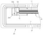
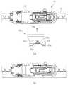
도 1에는 본 발명에 따른 와이퍼 블레이드의 포장용기의 분리 사시도가 도시되어 있다. 도 2의 (a)에는 와이퍼 블레이드가 포장된 상태의 포장용기의 평면도가, 도 2의 (b)에는 와이퍼 블레이드가 제거된 상태의 포장용기의 하부 케이스의 평면도가 도시되어 있다.1 is an exploded perspective view of the packaging container of the wiper blade according to the present invention. FIG. 2A illustrates a plan view of the packaging container in which the wiper blade is packaged, and FIG. 2B illustrates a plan view of the lower case of the packaging container in which the wiper blade is removed.
도 3에는 본 발명에 따른 와이퍼 블레이드의 포장용기에 포함된 하부 케이스의 횡단면도가 도시되어 있으며, 특히 (a)에는 도 2(b)의 A-A 선을 따라 취해진 단면도가, (b)에는 도 2(b)의 B-B 선을 따라 취해진 단면도가, (c)에는 도 2(b)의 C-C 선을 따라 취해진 단면도가, (d)에는 도 2(b)의 D-D 선을 따라 취해진 단면도가 도시되어 있다.Figure 3 is a cross-sectional view of the lower case included in the packaging of the wiper blade according to the present invention, in particular (a) is a cross-sectional view taken along the line AA of Figure 2 (b), (b) Figure 2 ( A cross-sectional view taken along the line BB of b), a cross-sectional view taken along the line CC of FIG. 2 (b) is shown in (c), and a cross-sectional view taken along the line DD of FIG. 2 (b) is shown in (d).
도 4에는 도 2(b)의 E-E 선을 따라 취해진 상기 하부 케이스의 종단면도가 도시되어 있고, 도 5에는 상기 하부 케이스와 와이퍼 블레이드의 말단 사이의 결합을 설명하기 위한 주요부 평면도가 도시되어 있다. 그리고, 도 6에는 상기 하부 케이스와 와이퍼 블레이드의 결합을 설명하기 위한 주요부 종단면도가 도시되어 있고, 도 7에는 상기 하부 케이스와 와이퍼 블레이드의 결합을 설명하기 위한 횡단면도가 도시되어 있다.4 is a longitudinal cross-sectional view of the lower case taken along line E-E of FIG. 2 (b), and FIG. 5 is a plan view of the main portion for explaining the coupling between the lower case and the end of the wiper blade. And, Figure 6 is a longitudinal cross-sectional view of the main portion for explaining the coupling of the lower case and the wiper blade, Figure 7 is a cross-sectional view for explaining the coupling of the lower case and the wiper blade.
도 1 및 도 2에 도시된 바와 같이, 본 발명에 따른 와이퍼 블레이드의 포장용기는, 포장될 와이퍼 블레이드(10)를 수용할 수 있는 수용부(21)가 형성되어 있는 하부 케이스(20)와, 이 하부 케이스(20)를 덮어 수용부(21)를 밀폐하는 상부 케 이스(30)를 포함한다.As shown in Figure 1 and 2, the packaging container of the wiper blade according to the present invention, the
와이퍼 블레이드(10)는, 자동차의 유리면에 밀착되는 고무 재질의 와이퍼 스트립(11)과, 이 와이퍼 스트립(11)이 장착되어 있으며 와이퍼 스트립(11)이 유리면에 밀착될 수 있도록 탄성을 가지는 재질로 만들어지는 프레임(12)과, 이 프레임(12)을 자동차의 와이퍼 암에 연결시키기 위한 어댑터(13)를 포함한다.The
도 1에서는 와이퍼 블레이드(10)가 직선 형상을 가지는 것처럼 도시되어 있지만 이는 도시의 편의를 위한 것으로서, 외력이 가해지지 않는 한 와이퍼 블레이드(10)는 자동차의 만곡된 유리면에 밀착될 수 있도록 만곡된 형상을 갖는다.In FIG. 1, the
와이퍼 블레이드(10)의 형상은 프레임(12)의 탄성에 의해 만곡된 상태로 유지될 수 있으며, 본 발명의 포장용기는 프레임(12)을 갖는 와이퍼 블레이드(10)를 포장하기 위해 사용되는 것이 바람직하다.The shape of the
하부 케이스(20)에 형성된 수용부(21)의 내부에는 와이퍼 블레이드(10)의 프레임(12)이 곧바로 펴진 직선상태로 포장될 수 있도록 고정하기 위한 복수의 제1 고정돌기(22) 및 제2 고정돌기(23)가 돌출 형성된다.The plurality of
제1 고정돌기(22)는 프레임(12)의 상부 표면(본 명세서에서 "상부"란 프레임(12)에 설치된 어댑터(13)가 돌출되는 방향을 의미한다.)에 맞닿고, 제2 고정돌기(23)는 프레임(12)의 하부 표면(본 명세서에서 "하부"란 프레임(12)에 설치된 어댑터(13)가 돌출되는 방향의 반대방향을 의미한다.)에 맞닿는다. 그에 따라, 제1 고정돌기(22)와 제2 고정돌기(23)는, 프레임(12)의 상하부를 동시에 반대방향에서 지지할 수 있어, 하부 케이스(20)에 수용된 프레임(12)이 직선형상을 유지할 수 있 게 한다.The
또한, 도 2에 도시된 바와 같이, 제1 고정돌기(22)는 어댑터(13) 주위, 즉 프레임(12)의 중앙 부분에서 프레임(12)의 상부표면에 맞닿을 수 있는 위치에 형성되고, 제2 고정돌기(23)는 프레임(12)의 양쪽 말단 부분에서 프레임(12)의 하부표면 및 끝면에 맞닿을 수 있는 위치에 형성되는 것이 바람직하다.In addition, as shown in FIG. 2, the
도 2는 본 발명에 따른 와이퍼 블레이드의 포장용기의 평면도로서, (a)에는 와이퍼 블레이드(10)가 하부 케이스(20) 내에 포장되어 있는 상태의 평면도가 도시되어 있고, (b)에는 상부 케이스(30)와 와이퍼 블레이드(10)가 제거된 후 하부 케이스(20)만의 평면도가 도시되어 있다.2 is a plan view of the packaging container of the wiper blade according to the present invention, (a) is a plan view of the
도 2 및 도 5에 도시된 바와 같이, 제2 고정돌기(23)는, 제1 고정돌기(22)와 협력하여 프레임(12)을 직선 상태로 유지하는 역할을 수행하는 동시에, 프레임(12)의 양쪽 끝면에 맞닿아 프레임(12)의 움직임을 제한하는 역할을 수행할 수 있다.As shown in FIG. 2 and FIG. 5, the
이를 위해 제2 고정돌기(23)는 ㄱ자 혹은 ㄴ자 형태로 절곡된 절곡부(23a)를 가지는 것이 바람직하다. 또한, 프레임(12)의 말단을 제2 고정돌기(23)의 절곡부(23a)에 확실하게 위치시킬 수 있도록, 절곡부(23a)의 모서리에 작은 오목 홈부(23b)를 형성하고, 이 오목 홈부(23b)에 프레임(12)의 말단을 탄성적으로 끼워서 결합시키는 것이 바람직하다.To this end, it is preferable that the
제2 고정돌기(23), 즉 하부 케이스(20)는 일반적으로 포장용기 등에 많이 사용되는 플라스틱 소재로 만들어질 수 있으며, 이러한 플라스틱 소재는 자체적으로 탄성을 가지므로, 오목 홈부(23b)에 프레임(12)의 말단을 탄성적으로 결합시키는 것이 가능하다.The
한편, 다시 도 1 및 도 2를 참조하면, 하부 케이스(20)에 형성된 수용부(21) 내에는 상술한 제1 고정돌기(22) 및 제2 고정돌기(23) 이외에도, 제1 고정돌기(22)와 협력하여 프레임(12)을 끼워 고정하기 위한 제3 고정돌기(24)가 형성될 수 있다.Meanwhile, referring back to FIGS. 1 and 2, in addition to the above-described
제3 고정돌기(24)는 프레임(12)을 중심으로 제1 고정돌기(22)의 반대쪽에 형성되며, 제1 고정돌기(22)과 제3 고정돌기(24)가 번갈아 배치될 수 있도록 형성되는 것이 바람직하다.The
도면에는 제1 고정돌기(22)가 2개소에 형성되고 제3 고정돌기(24)가 3개소에 형성된 것으로 도시되어 있지만, 이는 예시일 뿐이며 제1 고정돌기(22) 및 제3 고정돌기(24)의 개수에 의해 본 발명이 한정되는 것은 아니다.Although the drawing shows that the
이와 같이 본 발명에 따르면, 제1 고정돌기(22) 및 제2 고정돌기(23), 나아가서 제3 고정돌기(24)에 의해 와이퍼 블레이드(10)의 프레임(12)을 고정시키고 있다.As described above, according to the present invention, the
또한, 도 1 및 도 2에 도시된 바와 같이, 하부 케이스(20)의 수용부(21) 내에는, 자동차의 와이퍼 암과의 결합을 위해 와이퍼 블레이드(10)의 어댑터(13)에 형성되어 있는 결합구멍(13a)에 결합될 수 있는 결합돌기(25)가 형성되는 것이 바람직하다.In addition, as shown in Figures 1 and 2, in the
본 발명에 따르면, 포장된 와이퍼 블레이드(10)의 결합구멍(13a)에 하부 케이스(20)의 결합돌기(25)가 삽입되어 결합된 상태이므로, 포장용기의 개봉시 와이 퍼 블레이드(10)가 튀어나오는 것을 방지할 수 있다.According to the present invention, since the
도 3, 도 6 및 도 7에 도시된 바와 같이, 결합돌기(25)는, 어댑터(13)를 지지할 수 있도록 평평하게 돌출되는 베이스 부(25a)와, 이 베이스 부(25a)로부터 대략 원통형상을 가지도록 돌출되어 어댑터(13)에 형성된 결합구멍(13a)에 끼워지는 원통형 돌출부(25b)를 포함할 수 있다.As shown in FIGS. 3, 6 and 7, the engaging
원통형 돌출부(25b)의 말단에는, 어댑터(13)와의 결합상태를 확실하게 유지할 수 있도록, 환형 볼록부(25c)가 형성되는 것이 바람직하다. 원통형 돌출부(25b)가 어댑터(13)의 결합구멍(13a)에 끼워질 때 탄성 변형되는 환형 볼록부(25c)로 인하여, 결합된 어댑터(13)는 쉽게 이탈할 수 없게 된다.At the end of the
또한, 결합돌기(25)의 베이스 부(25a)와 원통형 돌출부(25b)가 연결되는 부분에는, 도 3의 (b), 도 5 및 도 6에 도시된 바와 같이, 원통형 돌출부(25b) 주위의 베이스 부(25a)가 오목하게 함몰되어 이루어지는 환형 오목부(25d)가 형성될 수 있다.In addition, as shown in FIGS. 3B, 5, and 6, the
도면에서는 와이퍼 블레이드(10)의 어댑터(13)에 자동차의 와이퍼 암이 삽입되어 결합되기 위한 결합구멍(13a)이 형성되어 있으며, 포장용기의 하부 케이스(20)에는 이 결합구멍(13a)에 삽입될 수 있는 형상의 결합돌기(25)가 형성되어 있는 것으로 도시하고 있다. 하지만, 어댑터에 원형의 결합구멍이 형성되어 있지 않은 형태의 와이퍼 블레이드의 경우에도, 어댑터와의 사이에서 탄성적으로 결합하여 이 어댑터를 고정시킬 수 있는 형상의 결합돌기를 포장용기의 하부 케이스에 형성하도록 본 발명을 변형시킬 수 있다.In the drawing, a
한편, 하부 케이스(20)의 수용부(21) 주위에는 상부 케이스(30)와의 결합을 위해 수용부(21)의 상단에서 수평방향으로 연장되는 플랜지 부(26)가 형성될 수 있으며, 이 플랜지 부(26) 상에는 하나 이상의 제1 요철부(27)가 형성될 수 있다.Meanwhile, a
또한, 상부 케이스(30)의 주위에는 제1 요철부(27)에 상응하는 형상의 제2 요철부(31)가 형성될 수 있으며, 도 7에 도시된 바와 같이, 이들 제1 요철부(27)와 제2 요철부(31) 사이의 결합을 통하여 하부 케이스(20)와 상부 케이스(30)가 서로 조립될 수 있다.In addition, a second
도 7을 참조하면, 상부 케이스(30)의 중앙 부분은 위쪽으로 둥글게 튀어나와 있지만, 이 중앙 부분이 곡면 형상을 가지는 대신에 사각 형상을 가지면서 볼록하게 튀어나오도록 변형될 수 있다.Referring to FIG. 7, the center portion of the
또한, 상부 케이스(30)가 하부 케이스(20)와는 별개의 부품으로 제조된 후 하부 케이스(20)에 결합됨으로써 포장 용기가 완성되는 것을 예로 들어 설명이 이루어졌지만, 상부 케이스가 하부 케이스의 일측에 일체로 연결되도록 변형될 수 있음은 물론이다. 이 경우, 상부 케이스를 선회시킴으로써 상부 케이스와 하부 케이스를 서로 결합시킬 수 있다.In addition, although the
이상과 같이 본 발명에 따른 와이퍼 블레이드의 포장용기를, 예시된 도면을 참조하여 설명하였으나, 본 발명은 이상에서 설명된 실시예와 도면에 의해 한정되지 않으며, 특허청구범위 내에서 본 발명이 속하는 기술분야에서 통상의 지식을 가진 자들에 의해 다양한 수정 및 변형이 이루어질 수 있음은 물론이다.As described above, the packaging container of the wiper blade according to the present invention has been described with reference to the illustrated drawings, but the present invention is not limited to the embodiments and drawings described above, the present invention within the claims Of course, various modifications and variations can be made by those skilled in the art.
도 1은 본 발명에 따른 와이퍼 블레이드의 포장용기의 분리 사시도,1 is an exploded perspective view of the packaging container of the wiper blade according to the present invention,
도 2는 본 발명에 따른 와이퍼 블레이드의 포장용기의 평면도로서, (a)는 와이퍼 블레이드가 포장된 상태의 평면도이고, (b)는 와이퍼 블레이드가 제거된 상태의 하부 케이스의 평면도,2 is a plan view of the packaging container of the wiper blade according to the present invention, (a) is a plan view of the wiper blade is packed, (b) is a plan view of the lower case of the wiper blade is removed,
도 3은 본 발명에 따른 와이퍼 블레이드의 포장용기에 포함된 하부 케이스의 횡단면도로서, (a)는 도 2(b)의 A-A 선을 따라 취해진 단면도이고, (b)는 도 2(b)의 B-B 선을 따라 취해진 단면도이고, (c)는 도 2(b)의 C-C 선을 따라 취해진 단면도이고, (d)는 도 2(b)의 D-D 선을 따라 취해진 단면도,Figure 3 is a cross-sectional view of the lower case included in the packaging of the wiper blade according to the present invention, (a) is a cross-sectional view taken along the line AA of Figure 2 (b), (b) is BB of Figure 2 (b) (C) is a sectional view taken along the line CC of FIG. 2 (b), (d) is a sectional view taken along the line DD of FIG. 2 (b),
도 4는 도 2(b)의 E-E 선을 따라 취해진 본 발명에 따른 와이퍼 블레이드의 포장용기의 하부 케이스의 종단면도,4 is a longitudinal cross-sectional view of the lower case of the packaging container of the wiper blade according to the present invention taken along line E-E of FIG. 2 (b);
도 5는 본 발명에 따른 와이퍼 블레이드의 포장용기의 하부 케이스와 와이퍼 블레이드의 말단 사이의 결합을 설명하기 위한 주요부 평면도,5 is a plan view of the main part for explaining the coupling between the lower case of the packaging container of the wiper blade and the end of the wiper blade according to the present invention;
도 6은 본 발명에 따른 와이퍼 블레이드의 포장용기의 하부 케이스와 와이퍼 블레이드의 결합을 설명하기 위한 주요부 종단면도, 그리고Figure 6 is a longitudinal cross-sectional view of the main part for explaining the coupling of the lower case and the wiper blade of the packaging container of the wiper blade according to the present invention, and
도 7은 본 발명에 따른 와이퍼 블레이드의 포장용기의 하부 케이스와 와이퍼 블레이드의 결합을 설명하기 위한 횡단면도이다.Figure 7 is a cross-sectional view for explaining the coupling of the lower case and the wiper blade of the packaging container of the wiper blade according to the present invention.
< 도면의 주요 부분에 대한 부호의 설명>Description of the Related Art
10 : 와이퍼 블레이드 11 : 와이퍼 스트립10: wiper blade 11: wiper strip
12 : 프레임 13 : 어댑터12: frame 13: adapter
13a : 결합구멍 20 : 하부 케이스13a: coupling hole 20: lower case
21 : 수용부 22 : 제1 고정돌기21: accommodating part 22: first fixing projection
23 : 제2 고정돌기 23a : 절곡부23: second fixing
23b : 오목 홈부 24 : 제3 고정돌기23b: concave groove 24: third fixing projection
25 : 결합돌기 25a : 베이스 부25: engaging
25b : 원통형 돌출부 25c : 환형 볼록부25b:
25d : 환형 오목부 26 : 플랜지 부25d: annular recess 26: flange
27 : 제1 요철부 30 : 상부 케이스27: first uneven portion 30: upper case
31 : 제2 요철부31: second uneven portion
Claims (11)
Translated fromKoreanPriority Applications (9)
| Application Number | Priority Date | Filing Date | Title |
|---|---|---|---|
| KR1020090050371AKR101038203B1 (en) | 2009-06-08 | 2009-06-08 | Package of wiper blade |
| JP2009190648AJP4965610B2 (en) | 2009-06-08 | 2009-08-20 | Wiper blade packaging container |
| CA2678918ACA2678918C (en) | 2009-06-08 | 2009-09-17 | Packaging case for wiper blade |
| CN2009101719092ACN101905783B (en) | 2009-06-08 | 2009-09-18 | Packaging case for wiper blade |
| EP09170889AEP2261132B1 (en) | 2009-06-08 | 2009-09-22 | Packaging case for wiper blade |
| ES09170889TES2383635T3 (en) | 2009-06-08 | 2009-09-22 | Windshield wiper blade packaging box |
| AT09170889TATE546379T1 (en) | 2009-06-08 | 2009-09-22 | PACKAGING FOR ONE WIPER BLADE |
| PL09170889TPL2261132T3 (en) | 2009-06-08 | 2009-09-22 | Packaging case for wiper blade |
| US12/565,572US7926659B2 (en) | 2009-06-08 | 2009-09-23 | Packaging case for a wiper blade |
Applications Claiming Priority (1)
| Application Number | Priority Date | Filing Date | Title |
|---|---|---|---|
| KR1020090050371AKR101038203B1 (en) | 2009-06-08 | 2009-06-08 | Package of wiper blade |
Publications (2)
| Publication Number | Publication Date |
|---|---|
| KR20100131663A KR20100131663A (en) | 2010-12-16 |
| KR101038203B1true KR101038203B1 (en) | 2011-05-31 |
Family
ID=42227795
Family Applications (1)
| Application Number | Title | Priority Date | Filing Date |
|---|---|---|---|
| KR1020090050371AExpired - Fee RelatedKR101038203B1 (en) | 2009-06-08 | 2009-06-08 | Package of wiper blade |
Country Status (9)
| Country | Link |
|---|---|
| US (1) | US7926659B2 (en) |
| EP (1) | EP2261132B1 (en) |
| JP (1) | JP4965610B2 (en) |
| KR (1) | KR101038203B1 (en) |
| CN (1) | CN101905783B (en) |
| AT (1) | ATE546379T1 (en) |
| CA (1) | CA2678918C (en) |
| ES (1) | ES2383635T3 (en) |
| PL (1) | PL2261132T3 (en) |
Cited By (1)
| Publication number | Priority date | Publication date | Assignee | Title |
|---|---|---|---|---|
| KR20220139220A (en) | 2021-04-07 | 2022-10-14 | 배성순 | Automobile Wiper Blade case |
Families Citing this family (35)
| Publication number | Priority date | Publication date | Assignee | Title |
|---|---|---|---|---|
| US8910789B2 (en)* | 2009-11-02 | 2014-12-16 | Portage Plastics Corporation | Reclosable wiper blade package with improved package closure arrangement |
| US20130227809A1 (en) | 2012-02-24 | 2013-09-05 | Pylon Manufacturing Corp. | Wiper blade |
| USD686912S1 (en)* | 2010-09-13 | 2013-07-30 | Trico Products Corporation | Windshield wiper package |
| US8613357B2 (en)* | 2010-10-27 | 2013-12-24 | Portage Plastics Corporation | Reclosable upside down beam blade wiper blade package |
| US9457768B2 (en) | 2011-04-21 | 2016-10-04 | Pylon Manufacturing Corp. | Vortex damping wiper blade |
| US9174609B2 (en) | 2011-04-21 | 2015-11-03 | Pylon Manufacturing Corp. | Wiper blade with cover |
| MX345011B (en) | 2011-07-28 | 2017-01-11 | Pylon Mfg Corp | Windshield wiper adapter, connector and assembly. |
| US9108595B2 (en) | 2011-07-29 | 2015-08-18 | Pylon Manufacturing Corporation | Windshield wiper connector |
| FR2979602B1 (en)* | 2011-09-06 | 2013-12-20 | Valeo Systemes Dessuyage | PACKAGING DEVICE AND PACKAGING FOR CURVED BLADE WIPER BLADE AND INTEGRATED FLEXIBLE STRUCTURE |
| DE102011083955A1 (en)* | 2011-10-04 | 2013-04-04 | Robert Bosch Gmbh | Device for packaging a wiper blade |
| US8505724B2 (en)* | 2011-10-26 | 2013-08-13 | Display Pack, Inc. | Package assembly for wiper blade |
| US20130219649A1 (en) | 2012-02-24 | 2013-08-29 | Pylon Manufacturing Corp. | Wiper blade |
| US10723322B2 (en) | 2012-02-24 | 2020-07-28 | Pylon Manufacturing Corp. | Wiper blade with cover |
| US10829092B2 (en) | 2012-09-24 | 2020-11-10 | Pylon Manufacturing Corp. | Wiper blade with modular mounting base |
| USD692750S1 (en) | 2012-11-15 | 2013-11-05 | Trico Products Corporation | Wiper blade package |
| US8800769B2 (en) | 2012-11-15 | 2014-08-12 | Trico Products Corporation | Packaging assembly for wiper assembly |
| WO2014145351A1 (en) | 2013-03-15 | 2014-09-18 | Kevin Putnam | Reclosable package with anti stake latches |
| US10166951B2 (en) | 2013-03-15 | 2019-01-01 | Pylon Manufacturing Corp. | Windshield wiper connector |
| US9555775B2 (en)* | 2013-03-15 | 2017-01-31 | Illinois Tool Works Inc. | Connectors and connector kit for attachment of a windshield wiper blade to multiple types of windshield wiper arms |
| US9617036B2 (en) | 2013-03-15 | 2017-04-11 | Jay Baker | Packaging container having a secure closure mechanism |
| US9045256B2 (en) | 2013-03-15 | 2015-06-02 | Jay Baker | Packaging case for a windshield wiper blade |
| US9617039B2 (en) | 2013-03-15 | 2017-04-11 | Jay Baker | Packaging container having a closure and release mechanism |
| US9505380B2 (en) | 2014-03-07 | 2016-11-29 | Pylon Manufacturing Corp. | Windshield wiper connector and assembly |
| CN104127264B (en)* | 2014-06-19 | 2017-03-22 | 爱博诺德(北京)医疗科技有限公司 | One-step pre-loaded intraocular lens implantation system |
| USD787308S1 (en) | 2014-10-03 | 2017-05-23 | Pylon Manufacturing Corp. | Wiper blade package |
| USD777079S1 (en) | 2014-10-03 | 2017-01-24 | Pylon Manufacturing Corp. | Wiper blade frame |
| US20160304259A1 (en)* | 2015-04-14 | 2016-10-20 | Portage Plastics Corporation | Reclosable Pillow-Shaped Wiper Blade Package |
| USD765501S1 (en) | 2015-05-01 | 2016-09-06 | Pylon Manufacturing Corp. | Wiper blade package with sleeve |
| WO2017075066A1 (en) | 2015-10-26 | 2017-05-04 | Pylon Manufacturing Corp. | Wiper blade |
| US11040705B2 (en) | 2016-05-19 | 2021-06-22 | Pylon Manufacturing Corp. | Windshield wiper connector |
| WO2017201485A1 (en) | 2016-05-19 | 2017-11-23 | Pylon Manufacturing Corp. | Windshield wiper connector |
| WO2017201470A1 (en) | 2016-05-19 | 2017-11-23 | Pylon Manufacturing Corp. | Windshield wiper connector |
| EP3458315B1 (en) | 2016-05-19 | 2021-09-08 | Pylon Manufacturing Corp. | Windshield wiper blade |
| WO2017201458A1 (en) | 2016-05-19 | 2017-11-23 | Pylon Manufacturing Corp. | Windshield wiper connector |
| FR3056951B1 (en)* | 2016-10-04 | 2019-07-05 | Valeo Systemes D'essuyage | SUPPORT FRAME FOR WIPER BLADE, WIPER BLADE AND WIPING SYSTEM THEREFOR |
Citations (4)
| Publication number | Priority date | Publication date | Assignee | Title |
|---|---|---|---|---|
| KR20070032481A (en)* | 2005-09-16 | 2007-03-22 | 에이디엠이십일 주식회사 | Package of wiper blade |
| KR100764467B1 (en)* | 2006-04-04 | 2007-10-09 | 에이디엠이십일 주식회사 | Package of wiper blade |
| US20070235362A1 (en)* | 2006-04-07 | 2007-10-11 | Lewis Gregg S | Wiper blade package |
| KR100802026B1 (en)* | 2007-03-23 | 2008-02-12 | 주식회사 캐프 | Car Wiper Packaging |
Family Cites Families (21)
| Publication number | Priority date | Publication date | Assignee | Title |
|---|---|---|---|---|
| US4059219A (en) | 1976-01-30 | 1977-11-22 | Diamond International Corporation | Egg carton |
| US5353935A (en) | 1994-01-31 | 1994-10-11 | Anchor Wire Corporation | Blister package with reclosable card |
| JPH07315443A (en) | 1994-05-20 | 1995-12-05 | Fujitsu General Ltd | Packaging material |
| US5593036A (en) | 1995-11-02 | 1997-01-14 | Panoramic, Inc. | Locking package |
| US5699913A (en) | 1995-11-30 | 1997-12-23 | Cellstar, Ltd. | Unitized package assembly |
| US5584387A (en) | 1996-01-19 | 1996-12-17 | Grant; Richard B. | Combination book and package case assembly |
| US5899334A (en) | 1996-05-02 | 1999-05-04 | Portage Plastics Corporation | Reclosable transparent wiper blade package |
| JPH10291537A (en) | 1997-04-16 | 1998-11-04 | Maruenu Kk | Decorative container for receiving wiper |
| US6126008A (en) | 1998-01-26 | 2000-10-03 | The Brunton Company | Interactive packaging |
| JP2000177774A (en) | 1998-12-16 | 2000-06-27 | Kataoka Purasesu Kk | Toothbrush case |
| DE19951971A1 (en)* | 1999-10-28 | 2001-05-03 | Bosch Gmbh Robert | Packaging unit for a wiper blade for windshields of motor vehicles housed in this at least in some areas |
| US6321905B1 (en) | 2000-08-28 | 2001-11-27 | Emplast, Inc. | Security package |
| US6994213B2 (en) | 2001-09-18 | 2006-02-07 | Becton, Dickinson And Company | Packaging for push button blood collection set |
| TW500113U (en) | 2001-10-02 | 2002-08-21 | Clearco Product Ltd | Improved structure of windshield wiper packing box |
| DE10224431A1 (en)* | 2002-06-01 | 2003-12-11 | Bosch Gmbh Robert | Packaging for a wiper blade for windows of motor vehicles |
| FR2859713B1 (en) | 2003-09-15 | 2005-11-18 | Valeo Systemes Dessuyage | PACKING DEVICE FOR CURVED BLADE WIPER BLADE AND INTEGRATED FLEXIBLE STRUCTURE |
| KR100503326B1 (en) | 2003-10-16 | 2005-07-25 | 현대모비스 주식회사 | Packaging Case of a wiper blade for a vehicle |
| CN1997565A (en)* | 2004-05-03 | 2007-07-11 | 运输塑料制品公司 | Wiper blade package |
| WO2006080940A1 (en)* | 2004-05-03 | 2006-08-03 | Portage Plastics Corporation | Wiper blade package |
| KR100592339B1 (en)* | 2005-05-03 | 2006-06-21 | 박세헌 | Wiper Blade Packing Case |
| WO2010033646A2 (en)* | 2008-09-16 | 2010-03-25 | Portage Plastics Corporation | Reclosable beam blade wiper blade package |
- 2009
- 2009-06-08KRKR1020090050371Apatent/KR101038203B1/ennot_activeExpired - Fee Related
- 2009-08-20JPJP2009190648Apatent/JP4965610B2/enactiveActive
- 2009-09-17CACA2678918Apatent/CA2678918C/ennot_activeExpired - Fee Related
- 2009-09-18CNCN2009101719092Apatent/CN101905783B/ennot_activeExpired - Fee Related
- 2009-09-22PLPL09170889Tpatent/PL2261132T3/enunknown
- 2009-09-22ATAT09170889Tpatent/ATE546379T1/enactive
- 2009-09-22EPEP09170889Apatent/EP2261132B1/ennot_activeNot-in-force
- 2009-09-22ESES09170889Tpatent/ES2383635T3/enactiveActive
- 2009-09-23USUS12/565,572patent/US7926659B2/ennot_activeExpired - Fee Related
Patent Citations (4)
| Publication number | Priority date | Publication date | Assignee | Title |
|---|---|---|---|---|
| KR20070032481A (en)* | 2005-09-16 | 2007-03-22 | 에이디엠이십일 주식회사 | Package of wiper blade |
| KR100764467B1 (en)* | 2006-04-04 | 2007-10-09 | 에이디엠이십일 주식회사 | Package of wiper blade |
| US20070235362A1 (en)* | 2006-04-07 | 2007-10-11 | Lewis Gregg S | Wiper blade package |
| KR100802026B1 (en)* | 2007-03-23 | 2008-02-12 | 주식회사 캐프 | Car Wiper Packaging |
Cited By (1)
| Publication number | Priority date | Publication date | Assignee | Title |
|---|---|---|---|---|
| KR20220139220A (en) | 2021-04-07 | 2022-10-14 | 배성순 | Automobile Wiper Blade case |
Also Published As
| Publication number | Publication date |
|---|---|
| ATE546379T1 (en) | 2012-03-15 |
| JP2010280444A (en) | 2010-12-16 |
| PL2261132T3 (en) | 2012-08-31 |
| US7926659B2 (en) | 2011-04-19 |
| KR20100131663A (en) | 2010-12-16 |
| ES2383635T3 (en) | 2012-06-22 |
| CA2678918A1 (en) | 2010-12-08 |
| CN101905783A (en) | 2010-12-08 |
| JP4965610B2 (en) | 2012-07-04 |
| EP2261132B1 (en) | 2012-02-22 |
| US20100307940A1 (en) | 2010-12-09 |
| EP2261132A1 (en) | 2010-12-15 |
| CA2678918C (en) | 2012-12-04 |
| CN101905783B (en) | 2012-05-09 |
Similar Documents
| Publication | Publication Date | Title |
|---|---|---|
| KR101038203B1 (en) | Package of wiper blade | |
| KR100764467B1 (en) | Package of wiper blade | |
| KR100592339B1 (en) | Wiper Blade Packing Case | |
| TWI429011B (en) | Reusable resilient cushion for wafer container | |
| KR101685884B1 (en) | Resealable and refillable wipes dispenser | |
| US20220400824A1 (en) | Three-proof earbuds box protective case | |
| JP6150758B2 (en) | Egg container and label sealing method | |
| KR20170095945A (en) | Vial holder devices, methods and systems | |
| KR20100117894A (en) | Package case for wiper blade | |
| EP0002410B1 (en) | Container for a liquid such as perfume | |
| BR112015007097B1 (en) | ASSEMBLY PROCESS OF A PACKAGING DEVICE FOR COSMETIC PRODUCT AND PACKAGING DEVICE FOR COSMETIC PRODUCT | |
| CN103767285A (en) | Food container | |
| CN104080664B (en) | Wiper for vehicle | |
| US9517875B2 (en) | Packaging, use of a packaging and method for assembling several packaging | |
| KR20040019948A (en) | Container for receiving plates | |
| JP4181926B2 (en) | Substrate storage container | |
| KR100764468B1 (en) | Package of wiper blade | |
| JP6677471B2 (en) | Cosmetic container | |
| JP5309707B2 (en) | Optical device storage container | |
| JP4611563B2 (en) | Opening holder with lid for bag-like container | |
| JP3117305U (en) | Box with lid | |
| CN213472965U (en) | Connect firm car storage tank | |
| KR101804601B1 (en) | Packaging container for batteries | |
| JP4090757B2 (en) | Bottle holder | |
| JP5470230B2 (en) | Connecting container |
Legal Events
| Date | Code | Title | Description |
|---|---|---|---|
| A201 | Request for examination | ||
| PA0109 | Patent application | St.27 status event code:A-0-1-A10-A12-nap-PA0109 | |
| PA0201 | Request for examination | St.27 status event code:A-1-2-D10-D11-exm-PA0201 | |
| R18-X000 | Changes to party contact information recorded | St.27 status event code:A-3-3-R10-R18-oth-X000 | |
| R18-X000 | Changes to party contact information recorded | St.27 status event code:A-3-3-R10-R18-oth-X000 | |
| PG1501 | Laying open of application | St.27 status event code:A-1-1-Q10-Q12-nap-PG1501 | |
| D13-X000 | Search requested | St.27 status event code:A-1-2-D10-D13-srh-X000 | |
| D14-X000 | Search report completed | St.27 status event code:A-1-2-D10-D14-srh-X000 | |
| E701 | Decision to grant or registration of patent right | ||
| PE0701 | Decision of registration | St.27 status event code:A-1-2-D10-D22-exm-PE0701 | |
| GRNT | Written decision to grant | ||
| PR0701 | Registration of establishment | St.27 status event code:A-2-4-F10-F11-exm-PR0701 | |
| PR1002 | Payment of registration fee | St.27 status event code:A-2-2-U10-U11-oth-PR1002 Fee payment year number:1 | |
| PG1601 | Publication of registration | St.27 status event code:A-4-4-Q10-Q13-nap-PG1601 | |
| PN2301 | Change of applicant | St.27 status event code:A-5-5-R10-R11-asn-PN2301 | |
| PN2301 | Change of applicant | St.27 status event code:A-5-5-R10-R14-asn-PN2301 | |
| FPAY | Annual fee payment | Payment date:20140306 Year of fee payment:4 | |
| PR1001 | Payment of annual fee | St.27 status event code:A-4-4-U10-U11-oth-PR1001 Fee payment year number:4 | |
| FPAY | Annual fee payment | Payment date:20150421 Year of fee payment:5 | |
| PR1001 | Payment of annual fee | St.27 status event code:A-4-4-U10-U11-oth-PR1001 Fee payment year number:5 | |
| PR1001 | Payment of annual fee | St.27 status event code:A-4-4-U10-U11-oth-PR1001 Fee payment year number:6 | |
| R18-X000 | Changes to party contact information recorded | St.27 status event code:A-5-5-R10-R18-oth-X000 | |
| R18-X000 | Changes to party contact information recorded | St.27 status event code:A-5-5-R10-R18-oth-X000 | |
| FPAY | Annual fee payment | Payment date:20170418 Year of fee payment:7 | |
| PR1001 | Payment of annual fee | St.27 status event code:A-4-4-U10-U11-oth-PR1001 Fee payment year number:7 | |
| FPAY | Annual fee payment | Payment date:20180417 Year of fee payment:8 | |
| PR1001 | Payment of annual fee | St.27 status event code:A-4-4-U10-U11-oth-PR1001 Fee payment year number:8 | |
| FPAY | Annual fee payment | Payment date:20190418 Year of fee payment:9 | |
| PR1001 | Payment of annual fee | St.27 status event code:A-4-4-U10-U11-oth-PR1001 Fee payment year number:9 | |
| PC1903 | Unpaid annual fee | St.27 status event code:A-4-4-U10-U13-oth-PC1903 Not in force date:20200526 Payment event data comment text:Termination Category : DEFAULT_OF_REGISTRATION_FEE | |
| PC1903 | Unpaid annual fee | St.27 status event code:N-4-6-H10-H13-oth-PC1903 Ip right cessation event data comment text:Termination Category : DEFAULT_OF_REGISTRATION_FEE Not in force date:20200526 |