KR101037069B1 - Sterile adapter - Google Patents
Sterile adapterDownload PDFInfo
- Publication number
- KR101037069B1 KR101037069B1KR1020090089929AKR20090089929AKR101037069B1KR 101037069 B1KR101037069 B1KR 101037069B1KR 1020090089929 AKR1020090089929 AKR 1020090089929AKR 20090089929 AKR20090089929 AKR 20090089929AKR 101037069 B1KR101037069 B1KR 101037069B1
- Authority
- KR
- South Korea
- Prior art keywords
- instrument
- wheel
- protrusion
- adapter
- sterile adapter
- Prior art date
- Legal status (The legal status is an assumption and is not a legal conclusion. Google has not performed a legal analysis and makes no representation as to the accuracy of the status listed.)
- Active
Links
- 238000000034methodMethods0.000claimsdescription28
- 238000012856packingMethods0.000claimsdescription12
- 239000000463materialSubstances0.000claimsdescription11
- 230000001954sterilising effectEffects0.000claimsdescription7
- 239000000853adhesiveSubstances0.000claimsdescription6
- 230000001070adhesive effectEffects0.000claimsdescription6
- 230000002093peripheral effectEffects0.000claimsdescription3
- 238000001356surgical procedureMethods0.000description8
- 238000010168coupling processMethods0.000description5
- 239000012636effectorSubstances0.000description5
- 230000008569processEffects0.000description5
- 230000008878couplingEffects0.000description3
- 238000005859coupling reactionMethods0.000description3
- 238000004659sterilization and disinfectionMethods0.000description3
- 238000009795derivationMethods0.000description2
- 230000014509gene expressionEffects0.000description2
- 238000012986modificationMethods0.000description2
- 230000004048modificationEffects0.000description2
- 230000004044responseEffects0.000description2
- 208000032544CicatrixDiseases0.000description1
- 230000002457bidirectional effectEffects0.000description1
- 230000000740bleeding effectEffects0.000description1
- 201000010099diseaseDiseases0.000description1
- 208000037265diseases, disorders, signs and symptomsDiseases0.000description1
- 230000000694effectsEffects0.000description1
- 239000013013elastic materialSubstances0.000description1
- 238000005516engineering processMethods0.000description1
- 210000004400mucous membraneAnatomy0.000description1
- 210000000056organAnatomy0.000description1
- 230000001681protective effectEffects0.000description1
- 231100000241scarToxicity0.000description1
- 230000037387scarsEffects0.000description1
- 210000001519tissueAnatomy0.000description1
- 230000009466transformationEffects0.000description1
- 238000000844transformationMethods0.000description1
Images


Classifications
- A—HUMAN NECESSITIES
- A61—MEDICAL OR VETERINARY SCIENCE; HYGIENE
- A61B—DIAGNOSIS; SURGERY; IDENTIFICATION
- A61B46/00—Surgical drapes
- A61B46/10—Surgical drapes specially adapted for instruments, e.g. microscopes
- A—HUMAN NECESSITIES
- A61—MEDICAL OR VETERINARY SCIENCE; HYGIENE
- A61B—DIAGNOSIS; SURGERY; IDENTIFICATION
- A61B34/00—Computer-aided surgery; Manipulators or robots specially adapted for use in surgery
- A61B34/30—Surgical robots
- B—PERFORMING OPERATIONS; TRANSPORTING
- B25—HAND TOOLS; PORTABLE POWER-DRIVEN TOOLS; MANIPULATORS
- B25J—MANIPULATORS; CHAMBERS PROVIDED WITH MANIPULATION DEVICES
- B25J15/00—Gripping heads and other end effectors
- B25J15/04—Gripping heads and other end effectors with provision for the remote detachment or exchange of the head or parts thereof
- A—HUMAN NECESSITIES
- A61—MEDICAL OR VETERINARY SCIENCE; HYGIENE
- A61B—DIAGNOSIS; SURGERY; IDENTIFICATION
- A61B17/00—Surgical instruments, devices or methods
- A61B2017/00477—Coupling
- A—HUMAN NECESSITIES
- A61—MEDICAL OR VETERINARY SCIENCE; HYGIENE
- A61B—DIAGNOSIS; SURGERY; IDENTIFICATION
- A61B90/00—Instruments, implements or accessories specially adapted for surgery or diagnosis and not covered by any of the groups A61B1/00 - A61B50/00, e.g. for luxation treatment or for protecting wound edges
- A61B90/08—Accessories or related features not otherwise provided for
- A61B2090/0813—Accessories designed for easy sterilising, i.e. re-usable
Landscapes
- Health & Medical Sciences (AREA)
- Engineering & Computer Science (AREA)
- Surgery (AREA)
- Life Sciences & Earth Sciences (AREA)
- Animal Behavior & Ethology (AREA)
- Heart & Thoracic Surgery (AREA)
- Medical Informatics (AREA)
- Molecular Biology (AREA)
- Biomedical Technology (AREA)
- General Health & Medical Sciences (AREA)
- Public Health (AREA)
- Veterinary Medicine (AREA)
- Robotics (AREA)
- Nuclear Medicine, Radiotherapy & Molecular Imaging (AREA)
- Mechanical Engineering (AREA)
- Manipulator (AREA)
Abstract
Translated fromKoreanDescription
Translated fromKorean본 발명은 멸균 어댑터에 관한 것이다.The present invention relates to a sterile adapter.
의학적으로 수술이란 피부나 점막, 기타 조직을 의료 기계를 사용하여 자르거나 째거나 조작을 가하여 병을 고치는 말한다. 특히, 수술부위의 피부를 절개하여 열고 그 내부에 있는 기관 등을 치료, 성형하거나 제거하는 개복 수술 등은 출혈, 부작용, 환자의 고통, 흉터 등의 문제로 인하여 최근에는 로봇(robot)을 사용한 수술이 대안으로서 각광받고 있다.Medically, surgery refers to repairing a disease by cutting, slitting, or manipulating skin, mucous membranes, or other tissues with a medical device. In particular, open surgery, which incise the skin of the surgical site and open, treat, shape, or remove the organs inside of the surgical site, has recently been performed using robots due to problems such as bleeding, side effects, patient pain, and scars. This alternative is in the spotlight.
로봇 수술에 사용되는 수술용 로봇은 의사의 조작에 의해 신호를 생성하여 전송하는 마스터(master)부와, 마스터부로부터 신호를 받아 환자에 대해 수술에 필요한 조작을 수행하는 슬레이브(slave)부로 이루어지며, 마스터부와 슬레이브부는 통합된 하나의 로봇의 형태로 구현하거나, 각각 별도의 장치로 구성하여 수술실에 배치하게 된다.Surgical robot used in robot surgery consists of a master unit for generating and transmitting a signal by a doctor's operation, and a slave unit for receiving a signal from the master unit and performing an operation necessary for surgery on a patient. In this case, the master unit and the slave unit may be implemented in the form of an integrated robot or may be configured as separate devices and arranged in the operating room.
수술용 로봇에는 수술을 위한 각종 동작을 수행하기 위해 로봇 암이 구비되며, 로봇 암의 선단부에는 수술용 인스트루먼트(instrument)가 장착될 수 있도록 인스트루먼트 홀더가 형성된다. 로봇 암에 인스트루먼트를 장착하기 위해서는, 인 스트루먼트 홀더에 멸균 어댑터(sterile adapter)를 결합하고, 멸균 어댑터에 인스트루먼트의 하우징을 끼워 넣는 방식으로 인스트루먼트가 로봇 암에 장착된다.The surgical robot is provided with a robot arm to perform various operations for surgery, and an instrument holder is formed at the tip of the robot arm to mount a surgical instrument. To mount the instrument to the robot arm, the instrument is mounted to the robot arm by coupling a sterile adapter to the instrument holder and inserting the housing of the instrument into the sterile adapter.
인스트루먼트 홀더에는 로봇에서 생성되는 구동력을 인스트루먼트로 전달하기 위한 구동휠이 형성되고, 인스트루먼트에도 구동력을 전달받기 위한 구동휠이 형성되며, 멸균 어댑터에는 인스트루먼트 홀더에 형성된 구동휠 및 인스트루먼트에 형성된 구동휠에 각각 정합되는 휠이 형성된다.The drive holder is formed with a driving wheel for transmitting the driving force generated by the robot to the instrument, the drive wheel for receiving the driving force is also formed in the instrument, the sterile adapter in the drive wheel formed on the instrument holder and the drive wheel formed on the instrument, respectively A matching wheel is formed.
이러한 휠 구조가 서로 정합되도록 인스트루먼트 홀더에 멸균 어댑터를, 멸균 어댑터에 인스트루먼트를 장착하면, 로봇에서 생성된 구동력이 멸균 어댑터를 통해 인스트루먼트에 전달되며, 인스트루먼트의 구동휠에 연결된 와이어는 인스트루먼트의 말단부에 결합된 이펙터에 구동력을 전달함으로써, 이펙터가 움직여 수술에 필요한 다양한 조작이 이루어지게 된다.When the sterile adapter is mounted on the instrument holder and the instrument is mounted on the sterile adapter so that the wheel structure is matched with each other, the driving force generated by the robot is transmitted to the instrument through the sterile adapter, and the wire connected to the driving wheel of the instrument is connected to the end of the instrument. By transmitting the driving force to the effector, the effector moves and various manipulations necessary for surgery are performed.
이와 같이 수술용 로봇 암과 그에 장착되는 인스트루먼트 사이에는 멸균 어댑터가 개재되며, 멸균 어댑터에는 로봇 암 및 인스트루먼트와의 커플링(coupling) 구조가 구현되어 있다.As described above, a sterile adapter is interposed between the surgical robot arm and the instrument mounted thereon, and the sterile adapter implements a coupling structure with the robot arm and the instrument.
그러나, 종래의 멸균 어댑터에 형성되는 휠 구조는 탄성이 전혀 없는 구조로서, 멸균 어댑터를 로봇 암에 장착하기 위해 인스트루먼트 홀더에 형성된 구동휠에 스프링 가압식 탄성 구조를 적용해야 한다는 한계가 있었다.However, the wheel structure formed in the conventional sterile adapter has no elasticity at all, and there is a limitation in that a spring pressure elastic structure must be applied to the drive wheel formed in the instrument holder in order to mount the sterile adapter to the robot arm.
전술한 배경기술은 발명자가 본 발명의 도출을 위해 보유하고 있었거나, 본 발명의 도출 과정에서 습득한 기술 정보로서, 반드시 본 발명의 출원 전에 일반 공중에게 공개된 공지기술이라 할 수는 없다.The background art described above is technical information possessed by the inventors for the derivation of the present invention or acquired during the derivation process of the present invention, and is not necessarily a publicly known technique disclosed to the general public before the application of the present invention.
본 발명은, 로봇 암에 인스트루먼트를 용이하게 장착할 수 있는 멸균 어댑터를 제공하는 것이다.The present invention provides a sterile adapter capable of easily mounting an instrument to a robot arm.
본 발명의 일 측면에 따르면, 수술용 로봇 암에 형성되는 인스트루먼트 홀더와, 인스트루먼트 홀더에 장착되는 수술용 인스트루먼트의 사이에 개재되는 어댑터로서, 인스트루먼트 홀더에 대향하는 제1 면과, 수술용 인스트루먼트에 대향하는 제2 면을 구비하는 몸체부와, 몸체부에 탄지되고 제1 면으로 노출되며, 인스트루먼트 홀더에 형성되는 제1 구동휠에 정합되는 제1 휠과, 몸체부에 탄지되고 제2 면으로 노출되며, 인스트루먼트에 형성되는 제2 구동휠에 정합되는 제2 휠을 포함하는 멸균 어댑터(sterile adapter)가 제공된다.According to an aspect of the present invention, an adapter interposed between an instrument holder formed on the surgical robot arm and a surgical instrument mounted to the instrument holder, the first surface facing the instrument holder and opposing the surgical instrument A body portion having a second surface, a first wheel that is supported by the body portion and exposed to the first surface, and is matched to a first drive wheel formed in the instrument holder, and which is supported by the body portion and exposed to the second surface. A sterile adapter is provided that includes a second wheel that is mated to a second drive wheel formed in the instrument.
제1 구동휠에는 제1 돌기가 돌설되고(또는 제1 홈이 함입, 형성되고), 제1 휠에는 제1 돌기에 상응하는 제1 홈이 형성되며(또는 제1 홈에 상응하는 제1 돌기가 돌설되며), 멸균 어댑터를 인스트루먼트 홀더에 장착하여 제1 돌기가 제1 홈에 삽입되지 않을 경우, 제1 휠은 제1 돌기에 의해 가압되어 제1 면으로부터 함입될 수 있다. 이 경우 제1 구동휠을 회전시킴에 따라, 제1 돌기가 제1 홈에 삽입되어 제1 휠이 제1 구동휠에 정합되도록, 제1 휠이 탄성력에 의해 원래의 위치로 복귀할 수 있다.The first driving wheel is provided with the first projection (or the first groove is recessed and formed), and the first wheel is formed with the first groove corresponding to the first projection (or the first projection corresponding to the first groove). If the first protrusion is not inserted into the first groove by mounting the sterile adapter to the instrument holder, the first wheel may be pressed by the first protrusion to be recessed from the first surface. In this case, as the first driving wheel is rotated, the first wheel may be returned to its original position by the elastic force so that the first protrusion is inserted into the first groove so that the first wheel is engaged with the first driving wheel.
제2 휠에는 제2 돌기가 돌설되고(또는 제2 홈이 함입, 형성되고), 제2 구동휠에는 제2 돌기에 상응하는 제2 홈이 형성되며(또는 제2 홈에 상응하는 제2 돌기가 돌설되며), 수술용 인스트루먼트를 멸균 어댑터에 장착하여 제2 돌기가 제2 홈에 삽입되지 않을 경우, 제2 휠은 제2 돌기에 의해 가압되어 제2 면으로부터 함입될 수 있다. 이 경우 제2 휠을 회전시킴에 따라, 제2 돌기가 제2 홈에 삽입되어 제2 휠이 제2 구동휠에 정합되도록, 제2 휠이 탄성력에 의해 원래의 위치로 복귀할 수 있다.The second wheel is provided with a second projection (or a second groove is formed and formed), and the second drive wheel is formed with a second groove corresponding to the second projection (or a second projection corresponding to the second groove). If the second protrusion is not inserted into the second groove by mounting the surgical instrument to the sterile adapter, the second wheel may be pressed by the second protrusion to be recessed from the second surface. In this case, as the second wheel is rotated, the second wheel may be returned to its original position by the elastic force so that the second protrusion is inserted into the second groove so that the second wheel is engaged with the second driving wheel.
몸체부는, 제1 면에 상응하는 제1 판재와, 제2 면에 상응하며, 제1 판재로부터 이격 또는 근접 가능하도록 제1 판재에 결합되는 제2 판재를 포함할 수 있다.The body portion may include a first plate corresponding to the first face and a second plate corresponding to the second face and coupled to the first plate so as to be separated from or close to the first plate.
제2 판재의 양 측부에는, 인스트루먼트가 슬라이딩 방식으로 장착되도록 인스트루먼트의 이동 경로를 규정하는 가이드 레일(guide rail)이 돌설될 수 있다. 인스트루먼트의 단부에는 정렬홈이 함입되고, 제2 판재의 일단부에는 정렬홈에 정합되어 인스트루먼트가 소정의 위치에 정렬되도록 하는 정렬돌기가 돌설될 수 있다. 제2 판재의 타단부에는, 장착된 인스트루먼트가 그 장착 방향의 역(逆)방향으로 이동하는 것을 제한하는 스토퍼(stopper)가 돌설될 수 있다.On both sides of the second plate, guide rails may be formed which define the movement path of the instrument such that the instrument is mounted in a sliding manner. An end of the instrument may include an alignment groove, and one end of the second plate may be aligned with the alignment groove so that the alignment protrusion may be aligned so that the instrument is aligned at a predetermined position. At the other end of the second plate, a stopper may protrude that restricts the movement of the mounted instrument in the reverse direction of its mounting direction.
제2 판재를 제1 판재로부터 이격시킨 상태에서 인스트루먼트를 장착한 후, 제2 판재를 제1 판재에 근접시켜 제2 휠이 제2 판재로부터 돌출되도록 함으로써, 제2 휠이 제2 구동휠에 정합될 수 있다.After mounting the instrument with the second plate separated from the first plate, the second wheel is brought into proximity with the first plate so that the second wheel protrudes from the second plate so that the second wheel mates to the second drive wheel. Can be.
제2 판재에는 제1 면을 향하여 고정돌기가 돌설되고, 제1 판재에는 고정돌 기가 수용되는 관통홀이 천공되며, 제1 판재와 제2 판재를 서로 근접시킴에 따라 고정돌기는 관통홀을 관통하여 제1 면으로부터 돌출될 수 있다.In the second plate, fixing protrusions protrude toward the first surface, and through holes in which the fixing protrusions are accommodated are drilled in the first plate. To protrude from the first surface.
수술용 로봇 암은 멸균 드레이프(sterile drape)에 의해 커버되고, 멸균 드레이프에는, 멸균 어댑터가 인스트루먼트 홀더에 장착되는 위치에 상응하여 개방홀이 천공될 수 있다. 멸균 어댑터를 인스트루먼트 홀더에 장착함에 따라, 제1 면으로부터 돌출된 고정돌기가 개방홀의 외주부를 가압하여, 멸균 드레이프가 인스트루먼트 홀더에 밀착되도록 할 수 있다. 인스트루먼트 홀더의 주변에는 개방홀의 외주부에 상응하여 패킹재가 부착되며, 패킹재는 돌출된 고정돌기에 의해 가압되어 그 형상이 변형될 수 있다.The surgical robot arm is covered by a sterile drape, and the sterile drape can be perforated with an open hole corresponding to the position where the sterile adapter is mounted to the instrument holder. As the sterile adapter is attached to the instrument holder, the fixing protrusion protruding from the first surface may press the outer circumference of the opening so that the sterile drape may be in close contact with the instrument holder. The packing material is attached to the periphery of the instrument holder corresponding to the outer circumferential portion of the opening, the packing material is pressed by the protruding fixing projections may be deformed shape.
개방홀의 외주부에는 멸균 어댑터가 부착되도록 접착부가 형성될 수 있으며, 또한 멸균 어댑터가 부착되는 위치를 지시하는 마크가 표시될 수 있다.The outer periphery of the opening can be formed with an adhesive portion to attach the sterile adapter, it may also be marked with a mark indicating the position where the sterile adapter is attached.
한편, 본 발명의 다른 측면에 따르면, 수술용 로봇 암에 형성되는 인스트루먼트 홀더와, 인스트루먼트 홀더에 장착되며 전기수술(Electrosurgery)을 위한 제1 전기접점을 구비하는 수술용 인스트루먼트의 사이에 개재되는 어댑터로서, 인스트루먼트가 장착되는 몸체부와, 제1 전기접점에 연결되어 인스트루먼트에 전원이 제공되도록 하는 제2 전기접점을 포함하는 멸균 어댑터가 제공된다.On the other hand, according to another aspect of the present invention, as an adapter interposed between the instrument holder formed on the surgical robot arm and the surgical instrument mounted to the instrument holder having a first electrical contact for electrosurgical (Electrosurgery) A sterile adapter is provided that includes a body portion on which the instrument is mounted, and a second electrical contact connected to the first electrical contact to provide power to the instrument.
인스트루먼트는 슬라이딩 방식으로 몸체부에 장착되고, 몸체부에는, 인스트루먼트가 안착되도록 인스트루먼트의 장착 방향의 단부에 단턱부가 돌설될 수 있다. 제1 전기접점은 인스트루먼트의 단턱부에 대향하는 면에 형성되고, 제2 전기접점은 단턱부에 형성될 수 있다.The instrument is mounted to the body portion in a sliding manner, and a stepped portion may protrude from the end portion in the mounting direction of the instrument so that the instrument is seated. The first electrical contact may be formed on a surface of the instrument facing the stepped portion, and the second electrical contact may be formed on the stepped portion.
전술한 것 외의 다른 측면, 특징, 잇점이 이하의 도면, 특허청구범위 및 발명의 상세한 설명으로부터 명확해질 것이다.Other aspects, features, and advantages other than those described above will become apparent from the following drawings, claims, and detailed description of the invention.
본 발명의 바람직한 실시예에 따르면, 멸균 어댑터에 형성된 휠이 양방향으로 눌릴 수 있도록 멸균 어댑터에 탄성 구조를 적용함으로써, 인스트루먼트 홀더나 인스트루먼트에 별도의 탄성 구조를 적용하지 않고도, 수술용 인스트루먼트를 로봇 암에 용이하고 간편하게 장착할 수 있다.According to a preferred embodiment of the present invention, by applying the elastic structure to the sterile adapter so that the wheel formed in the sterile adapter can be pressed in both directions, the surgical instrument to the robot arm, without applying a separate elastic structure to the instrument holder or instrument Easy and simple mounting
본 발명은 다양한 변환을 가할 수 있고 여러 가지 실시예를 가질 수 있는 바, 특정 실시예들을 도면에 예시하고 상세하게 설명하고자 한다. 그러나, 이는 본 발명을 특정한 실시 형태에 대해 한정하려는 것이 아니며, 본 발명의 사상 및 기술 범위에 포함되는 모든 변환, 균등물 내지 대체물을 포함하는 것으로 이해되어야 한다. 본 발명을 설명함에 있어서 관련된 공지 기술에 대한 구체적인 설명이 본 발명의 요지를 흐릴 수 있다고 판단되는 경우 그 상세한 설명을 생략한다.The present invention is capable of various modifications and various embodiments, and specific embodiments are illustrated and described in the drawings. However, this is not intended to limit the present invention to specific embodiments, it should be understood to include all transformations, equivalents, and substitutes included in the spirit and scope of the present invention. In the following description of the present invention, if it is determined that the detailed description of the related known technology may obscure the gist of the present invention, the detailed description thereof will be omitted.
제1, 제2 등의 용어는 다양한 구성요소들을 설명하는데 사용될 수 있지만, 상기 구성요소들은 상기 용어들에 의해 한정되어서는 안 된다. 상기 용어들은 하나의 구성요소를 다른 구성요소로부터 구별하는 목적으로만 사용된다.The terms first, second, etc. may be used to describe various components, but the components should not be limited by the terms. The terms are used only for the purpose of distinguishing one component from another.
본 출원에서 사용한 용어는 단지 특정한 실시예를 설명하기 위해 사용된 것 으로, 본 발명을 한정하려는 의도가 아니다. 단수의 표현은 문맥상 명백하게 다르게 뜻하지 않는 한, 복수의 표현을 포함한다. 본 출원에서, "포함하다" 또는 "가지다" 등의 용어는 명세서상에 기재된 특징, 숫자, 단계, 동작, 구성요소, 부품 또는 이들을 조합한 것이 존재함을 지정하려는 것이지, 하나 또는 그 이상의 다른 특징들이나 숫자, 단계, 동작, 구성요소, 부품 또는 이들을 조합한 것들의 존재 또는 부가 가능성을 미리 배제하지 않는 것으로 이해되어야 한다.The terminology used herein is for the purpose of describing particular example embodiments only and is not intended to be limiting of the invention. Singular expressions include plural expressions unless the context clearly indicates otherwise. In this application, the terms "comprise" or "have" are intended to indicate that there is a feature, number, step, operation, component, part, or combination thereof described in the specification, and one or more other features. It is to be understood that the present invention does not exclude the possibility of the presence or the addition of numbers, steps, operations, components, components, or a combination thereof.
이하, 본 발명의 실시예를 첨부한 도면들을 참조하여 상세히 설명하기로 하며, 첨부 도면을 참조하여 설명함에 있어, 동일하거나 대응하는 구성 요소는 동일한 도면번호를 부여하고 이에 대한 중복되는 설명은 생략하기로 한다.Hereinafter, embodiments of the present invention will be described in detail with reference to the accompanying drawings, and in the following description with reference to the accompanying drawings, the same or corresponding components are given the same reference numerals and redundant description thereof will be omitted. Shall be.
도 1은 본 발명의 실시예에 따른 멸균 어댑터를 나타낸 분해사시도이다. 도 1을 참조하면, 로봇 암(1), 인스트루먼트 홀더(3), 인스트루먼트(5), 멸균 어댑터(10), 몸체부(12), 제1 면(14), 제2 면(17), 제1 구동휠(30), 제1 휠(20), 제2 휠(24), 제2 구동휠(50)이 도시되어 있다.1 is an exploded perspective view showing a sterile adapter according to an embodiment of the present invention. Referring to FIG. 1, a robot arm 1, an
본 실시예는 멸균 어댑터에 장착되는 휠이 양방향, 즉 인스트루먼트 홀더에 결합되는 방향 및 인스트루먼트에 결합되는 방향으로 탄지되도록 탄성체를 부가함으로써, 인스트루먼트 홀더나 인스트루먼트는 별도의 탄성 구조를 적용할 필요 없이 수술용 인스트루먼트를 인스트루먼트 홀더에 장착할 수 있도록 한 것을 특징으로 한다.In this embodiment, by adding an elastic body so that the wheel mounted on the sterile adapter is bidirectional, i.e., the direction coupled to the instrument holder and the direction coupled to the instrument, the instrument holder or the instrument does not need to apply a separate elastic structure for surgery It is characterized in that the instrument can be mounted to the instrument holder.
즉, 종래와 같이 인스트루먼트 홀더에 스프링 등을 설치하여 구동휠에 탄성 을 부여하는 것이 아니라, 인스트루먼트를 인스트루먼트 홀더에 결합하도록 해주는 멸균 어댑터에 탄성을 부여한 것이다.In other words, by providing a spring or the like to the instrument holder as in the prior art to give elasticity to the drive wheel, it is to give elasticity to the sterile adapter to couple the instrument to the instrument holder.
본 실시예에 따른 멸균 어댑터(10)는, 인스트루먼트 홀더(3)에 수술용 인스트루먼트(5)를 장착하는 과정에서 그 사이에 개재되는 어댑터로서, 멸균 어댑터(10)를 이용하여 인스트루먼트(5)가 인스트루먼트 홀더(3)에 결합된다.The
본 실시예에 따른 멸균 어댑터(10)는 몸체부(12)를 기준으로 양면으로 노출되는 제1 휠(20)과 제2 휠(24)로 이루어지며, 제1, 제2 휠(20, 24)은 각각 몸체부(12)에 탄성적으로 지지된다는 특징을 갖는다. 즉, 몸체부(12)의 인스트루먼트 홀더(3)에 대향하는 면을 제1 면(14), 인스트루먼트(5)에 대향하는 면을 제2 면(17)이라 할 때, 제1 휠(20)은 제1 면(14)으로 노출되고, 제2 휠(24)은 제2 면(17)으로 노출되어, 제1, 제2 휠(20, 24)이 몸체부(12)의 양면으로 노출된다.
한편, 제1 휠(20) 및 제2 휠(24)은 각각 스프링 등의 탄성체(도 1의 'E')를 개재하여 몸체부(12)에 결합되며, 이에 따라 제1, 제2 휠(20, 24)은 외력에 의해 함입되고, 외력이 제거되면 탄성력에 의해 다시 원래의 위치로 복귀하게 된다. 즉, 제1 휠(20)과 제2 휠(24)은 서로 연결되어 같이 회전을 하는 한편, 스프링 등을 개재하여 몸체부(12)에 결합됨으로써, 제1 휠(20)과 제2 휠(24)이 서로 밀어내는 방향으로 탄성력이 인가되도록 구성된다.Meanwhile, the
본 실시예에 따른 멸균 어댑터(10)를 인스트루먼트 홀더(3)에 장착하면 제1 면(14)이 인스트루먼트 홀더(3)에 접하게 되며, 제1 면(14)으로 노출되는 제1 휠(20)은 인스트루먼트 홀더(3)에 형성되는 제1 구동휠(30)에 정합된다.When the
또한, 멸균 어댑터(10)에 수술용 인스트루먼트(5)를 장착하면 제2 면(17)이 인스트루먼트(5)에 접하게 되며, 제2 면(17)으로 노출되는 제2 휠(24)은 인스트루먼트(5)에 형성되는 제2 구동휠(50)에 정합된다. 이하, 본 실시예에 따른 멸균 어댑터(10)와 인스트루먼트 홀더(3) 및 인스트루먼트(5)가 결합되는 방식에 대해 구체적으로 설명한다.In addition, when the
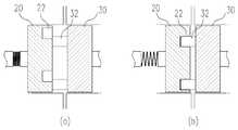
도 2a는 본 발명의 실시예에 따른 멸균 어댑터가 인스트루먼트 홀더에 장착되는 상태를 나타낸 도면이고, 도 2b는 도 2a의 'A'에 대한 단면도이고, 도 3a는 본 발명의 실시예에 따른 수술용 인스트루먼트가 멸균 어댑터에 장착되는 상태를 나타낸 도면이고, 도 3b는 도 3a의 'B'에 대한 단면도이다. 도 2a 내지 도 3b를 참조하면, 인스트루먼트 홀더(3), 인스트루먼트(5), 멸균 어댑터(10), 몸체부(12), 제1 면(14), 제2 면(17), 제1 구동휠(30), 돌기(32, 33), 제1 휠(20), 홈(22, 23), 제2 휠(24), 제2 구동휠(50)이 도시되어 있다.Figure 2a is a view showing a state in which the sterile adapter according to the embodiment of the present invention is mounted on the instrument holder, Figure 2b is a cross-sectional view of 'A' of Figure 2a, Figure 3a is a surgical according to an embodiment of the present invention FIG. 3B is a view illustrating a state in which an instrument is mounted on a sterile adapter, and FIG. 3B is a cross-sectional view of 'B' of FIG. 3A. 2A to 3B, the
먼저, 멸균 어댑터(10)와 인스트루먼트 홀더(3) 간의 결합 방식을 살펴보면, 인스트루먼트 홀더(3)에 형성된 제1 구동휠(30)에는 돌기(32)가 돌설되고, 제1 구동휠(30)에 대향하는 제1 휠(20)에는 돌기(32)가 삽입될 수 있는 홈(22)이 형성된다.First, looking at the coupling method between the
멸균 어댑터(10)를 인스트루먼트 홀더(3)에 장착함에 따라 제1 구동휠(30)과 제1 휠(20)은 서로 접하게 되는데, 이 때 돌기(32)가 홈(22)에 삽입되면 제1 구동휠(30)과 제1 휠(20)은 서로 정합될 것이나, 돌기(32)가 홈(22)에 삽입되지 않을 경우에는 돌기(32)에 의해 제1 휠(20)이 가압되게 된다. 전술한 바와 같이 제1 휠(20)은 멸균 어댑터(10)에 탄지되어 있으므로, 돌기(32)에 의해 제1 휠(20)이 가압되면, 도 2b의 (a)에 도시된 것처럼, 제1 휠(20)은 멸균 어댑터(10)의 표면(제1 면(14))으로부터 밀려들어간다.As the
이처럼 돌기(32)에 의해 제1 휠(20)이 함입된 상태에서, 제1 구동휠(30)을 좌우로 회전시키면, 어디에선가는 돌기(32)가 홈(22)에 삽입되는 경우가 발생하며, 이에 따라 돌기(32)가 제1 휠(20)을 가압하는 상태가 해제되게 된다. 이처럼, 돌기(32)에 의한 외력이 제거됨에 따라, 도 2b의 (b)에 도시된 것처럼, 제1 휠(20)은 탄성력에 의해 원래의 위치로 복귀하게 되며, 이로써 제1 휠(20)이 제1 구동휠(30)에 정합된다.As such, when the
이와 같이 제1 휠(20)이 제1 구동휠(30)에 정합된 상태에서 제1 구동휠(30)을 회전시키면 그에 따라 제1 휠(20)이 연동하여 회전하게 되므로, 로봇으로부터 생성된 구동력이 제1 구동휠(30)을 통해 제1 휠(20)로 전달된다.As such, when the
다음으로, 멸균 어댑터(10)와 수술용 인스트루먼트(5) 간의 결합 방식을 살펴보면, 제2 휠(24)에는 돌기(33)가 돌설되고, 제2 휠(24)에 대향하는 제2 구동휠(50)에는 돌기(33)가 삽입될 수 있는 홈(23)이 형성된다.Next, looking at the coupling method between the
멸균 어댑터(10)에 수술용 인스트루먼트(5)를 장착함에 따라 제2 구동휠(50)과 제2 휠(24)은 서로 접하게 되는데, 이 때 돌기(33)가 홈(23)에 삽입되면 제2 구동휠(50)과 제2 휠(24)은 서로 정합될 것이나, 돌기(33)가 홈(23)에 삽입되지 않을 경우에는 제2 구동휠(50)이 돌기(33)를 가압하고 그로 인하여 제2 휠(24) 이 가압되게 된다. 전술한 바와 같이 제2 휠(24)은 멸균 어댑터(10)에 탄지되어 있으므로, 돌기(33)로 인하여 제2 휠(24)이 가압되면, 도 3b의 (a)에 도시된 것처럼, 제2 휠(24)은 멸균 어댑터(10)의 표면(제2 면(17))으로부터 밀려들어간다.As the
이처럼 제2 휠(24)이 함입된 상태에서 제1 구동휠(30)을 좌우로 회전시키면, 제1 구동휠(30)에 정합된 제1 휠(20), 및 제1 휠(20)에 연결된 제2 휠(24)이 연동하여 회전하며, 이에 따라 돌기(33)가 홈(23)에 삽입되는 경우가 발생하여 제2 휠(24)이 가압된 상태가 해제된다. 이처럼, 외력이 제거됨에 따라, 도 3b의 (b)에 도시된 것처럼, 제2 휠(24)은 탄성력에 의해 원래의 위치로 복귀하게 되며, 이로써 제2 휠(24)과 제2 구동휠(50)이 서로 정합된다.As such, when the
이와 같이 제2 구동휠(50)과 제2 휠(24)이 정합된 상태에서 제1 구동휠(30)을 회전시키면 그에 따라 제1 휠(20), 제2 휠(24) 및 제2 구동휠(50)이 연동하여 회전하게 되므로, 로봇으로부터 생성되어 된 구동력이 제1 구동휠(30), 제1 휠(20) 및 제2 휠(24)을 통해 제2 구동휠(50)로 전달된다.As such, when the
제2 구동휠(50)은 인스트루먼트(5)의 말단부에 결합된 이펙터와 와이어에 의해 연결될 수 있는데, 전술한 것처럼 구동력이 제2 구동휠(50)로 전달되어 제2 구동휠(50)이 회전함에 따라, 와이어를 통해 구동력이 이펙터로 전달되어 이펙터가 작동되게 된다.The
여기에서는 제1 구동휠(30) 및 제2 휠(24)에 돌기(32, 33)가, 제1 휠(20) 및 제2 구동휠(50)에 홈(22, 23)이 형성되어 서로 정합되는 경우에 대해 설명하였으나, 돌기와 홈이 반드시 전술한 바와 같이 형성되어야 하는 것은 아니며, 한 쌍 의 휠의 어느 한쪽에는 돌기를, 다른 한 쪽에는 홈을 형성하여 서로 정합되도록 할 수 있다.In this case, the
나아가, 반드시 어느 하나의 휠에는 돌기를, 다른 하나의 휠에는 홈을 형성하여 정합되도록 해야 하는 것은 아니며, 한 쌍의 휠이 서로 정합되도록 할 수 있는 다양한 기구적(機構的) 구성을 적용할 수 있음은 물론이다.Furthermore, it is not necessary to form a protrusion on one wheel and a groove on another wheel, and various mechanical configurations may be applied to allow a pair of wheels to mate with each other. Of course.
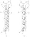
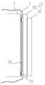
도 4a는 본 발명의 실시예에 따른 멸균 어댑터를 나타낸 사시도이고, 도 4b는 본 발명의 실시예에 따른 멸균 어댑터에 인스트루먼트가 장착되는 상태를 나타낸 정면도이고, 도 4c는 도 4b의 C-C'에 대한 단면도이고, 도 4d는 본 발명의 실시예에 따른 멸균 어댑터에 인스트루먼트가 장착되는 상태를 나타낸 단면도이다. 도 4a 내지 도 4d를 참조하면, 인스트루먼트(5), 멸균 어댑터(10), 몸체부(12), 제1 판재(15), 제2 판재(18), 제2 휠(24), 홈(23), 가이드 레일(26), 정렬홈(27), 정렬돌기(28), 스토퍼(29), 돌기(33), 제2 구동휠(50)이 도시되어 있다.Figure 4a is a perspective view showing a sterile adapter according to an embodiment of the present invention, Figure 4b is a front view showing a state in which the instrument is mounted to the sterile adapter according to an embodiment of the present invention, Figure 4c is a C-C 'of FIG. 4 is a cross-sectional view showing a state in which the instrument is mounted on the sterile adapter according to an embodiment of the present invention. 4A to 4D, the
본 실시예에 따른 멸균 어댑터(10)의 몸체부(12)는 서로 이격 또는 근접 가능하도록 결합되는 한 쌍의 판재(15, 18)로 구성할 수 있다. 즉, 제1 면(14)에 상응하여 인스트루먼트 홀더(3)에 접하는 제1 판재(15)와, 제2 면(17)에 상응하며 인스트루먼트(5)와 접하는 제2 판재(18)로 몸체부(12)를 구성하고, 제1 판재(15)와 제2 판재(18)는 서로 이격 또는 근접하도록 결합할 수 있다.The
이 경우, 도 4a에 도시된 것처럼, 제2 판재(18)의 양 측부에 가이드 레일(26)을 설치할 수 있는데, 본 실시예에 따른 가이드 레일(26)은 인스트루먼트(5) 가 멸균 어댑터(10)에 슬라이딩 방식으로 장착되도록 하는 이동 경로를 제공하는 역할을 한다.In this case, as shown in Figure 4a, it is possible to install the guide rails 26 on both sides of the
인스트루먼트(5)가 가이드 레일(26)을 따라 슬라이드 이동하여 멸균 어댑터(10)에 장착되도록 하기 위해, 도 4c에 도시된 것처럼 인스트루먼트(5)의 단면상 가이드 레일(26)에 상응하는 슬라이딩 레일 구조(도 4c의 'R' 참조)를 형성할 수 있다.In order for the
한편, 인스트루먼트(5)를 멸균 어댑터(10)에 슬라이딩 방식으로 장착할 경우, 인스트루먼트(5)가 멸균 어댑터(10) 상의 정확한 위치에 장착되도록 하기 위해, 본 실시예에 따른 인스트루먼트(5)에는 정렬(align) 수단이 형성될 수 있다. 즉, 도 4b에 도시된 것처럼 인스트루먼트(5)의 단부에 정렬홈(27)이 함입, 형성될 경우, 제2 판재(18)의 일단부에도 정렬홈(27)에 정합될 수 있는 정렬돌기(28)를 돌설(突設)할 수 있다.On the other hand, when the
도 4b의 (a)에 도시된 것처럼 인스트루먼트(5)를 슬라이드 이동시켜 멸균 어댑터(10)에 장착할 경우, 정렬홈(27)에 정렬돌기(28)가 정합될 때까지 인스트루먼트(5)를 이동시켜 장착함으로써 인스트루먼트(5)가 정확한 위치에 정렬되도록 할 수 있다.When the
본 실시예에 따른 정렬홈(27) 및 정렬돌기(28)는 미리 지정된 위치에서 인스트루먼트(5)가 멸균 어댑터(10)에 장착되도록 정렬하는 역할을 하는 것이므로, 정렬홈(27)과 정렬돌기(28) 사이에 유격(裕隔)이 발생하지 않도록 정교하게 제작할 수 있다.Since the
한편, 전술한 바와 같이 인스트루먼트(5)를 일 방향(장착 방향)으로 슬라이드 이동시켜 멸균 어댑터(10)에 장착할 경우, 인스트루먼트(5)가 멸균 어댑터(10)로부터 빠지지 않고 그 장착된 상태를 유지하도록, 즉 장착된 인스트루먼트(5)가 장착 방향의 역(逆)방향으로 이동하는 것을 제한하도록 스토퍼(29)를 돌설할 수 있다.On the other hand, when the
즉, 제2 판재(18)의 타단부에 스토퍼(29)를 설치함으로써, 도 4b의 (a)와 같이 인스트루먼트(5)를 이동시켜 도 4b의 (b)와 같이 장착한 후에, 스토퍼(29)가 돌출되도록 하여 인스트루먼트(5)가 역방향으로 빠지는 것을 방지할 수 있다.That is, by providing the
이를 위해, 본 실시예에 따른 스토퍼(29)는, 인스트루먼트(5)를 장착하는 과정에서는 제2 판재(18)로부터 돌출되지 않다가, 인스트루먼트(5)가 장착된 후에 돌출되어 인스트루먼트(5)를 잡아 줄 수 있도록, 탄성체 등에 의해 지지되도록 구성할 수 있다. 또한, 후술하는 바와 같이, 제2 판재(18)를 제1 판재(15)에 근접시킴에 따라 스토퍼(29)가 제2 판재(18)로부터 돌출되도록 할 수도 있다.To this end, the
한편, 전술한 바와 같이, 제2 휠(24)에는 돌기(33)를 돌설하고 제2 구동휠(50)에는 홈(23)을 형성하여 제2 구동휠(50)이 제2 휠(24)에 정합되도록 할 수 있는데, 인스트루먼트(5)를 슬라이드 이동시켜 멸균 어댑터(10)에 장착할 경우, 제2 면으로부터 돌출된 돌기(33)가 인스트루먼트(5)의 이동에 간섭이 되어 슬라이딩 방식에 의한 장착을 곤란하게 할 수 있다.Meanwhile, as described above, the
이 경우, 도 4d에 도시된 것처럼, 몸체부(12)를 서로 이격, 근접되는 한 쌍의 판재(15, 18)로 구성함으로써, 제2 휠(24)에 돌기(33)가 돌출된 상태에서도 인 스트루먼트(5)를 슬라이딩 방식으로 장착할 수 있다.In this case, as shown in FIG. 4D, the
즉, 도 4d의 (a)에 도시된 것처럼 제2 판재(18)를 제1 판재(15)로부터 이격시켜 제2 휠(24)의 돌기(33)가 제2 판재(18)의 표면으로부터 돌출되지 않도록 한 상태에서 인스트루먼트(5)를 장착하고, 인스트루먼트(5)가 장착된 후 도 4d의 (b)에 도시된 것처럼 제2 판재(18)를 눌러, 즉 제2 판재(18)를 제1 판재(15)에 근접시켜 돌기(33)가 제2 판재(18)의 표면으로부터 돌출되도록 할 수 있다. 이로써, 인스트루먼트(5)가 멸균 어댑터(10)에 장착되고, 제2 휠(24)이 제2 구동휠(50)에 정합될 수 있다.That is, as shown in (a) of FIG. 4D, the
한편, 제2 판재(18)를 눌러 돌기(33)가 제2 판재(18)로부터 돌출되도록 할 때, 돌기(33)가 홈(23)에 정확하게 삽입되지 않을 경우에는, 도 3b를 참조하여 설명한 바와 같이, 제2 휠(24)이 멸균 어댑터(10)에 탄지되어 있으므로, 제2 구동휠(50)이 돌기(33)를 가압하여 제2 휠(24)이 제2 판재(18)로부터 돌출되지 못하고 가압된 상태로 있게 되며, 이 상태에서 제2 휠(24)을 좌우로 회전시켜 돌기(33)가 홈(23)에 정합되도록 할 수 있음은 전술한 바와 같다.On the other hand, when the
도 5는 본 발명의 실시예에 따른 멸균 어댑터를 나타낸 단면도이고, 도 6은 본 발명의 실시예에 따른 멸균 어댑터가 개방홀을 통해 인스트루먼트 홀더(3)에 장착되는 상태를 나타낸 측면도이고, 도 7은 본 발명의 실시예에 따른 멸균 어댑터가 멸균 드레이프에 부착되는 상태를 나타낸 도면이다. 도 5 내지 도 7을 참조하면, 로봇 암(1), 인스트루먼트 홀더(3), 인스트루먼트(5), 멸균 드레이프(7), 멸균 어 댑터(10), 몸체부(12), 제1 면(14), 제1 판재(15), 관통홀(16), 제2 면(17), 제2 판재(18), 고정돌기(19), 제1 구동휠(30), 패킹재(34), 제1 휠(20), 제2 휠(24), 제2 구동휠(50), 개방홀(72), 접착부(74), 마크(76)가 도시되어 있다.5 is a cross-sectional view showing a sterile adapter according to an embodiment of the present invention, Figure 6 is a side view showing a state in which the sterile adapter according to an embodiment of the present invention is mounted to the instrument holder (3) through the opening hole, Figure 7 Is a view showing a state in which a sterile adapter according to an embodiment of the present invention is attached to a sterile drape. 5 to 7, the robot arm 1, the
전술한 바와 같이, 본 실시예에 따른 멸균 어댑터(10)의 몸체부(12)는 서로 이격 또는 근접 가능하도록 결합되는 한 쌍의 판재(15, 18)로 구성할 수 있으며, 이 경우, 제2 판재(18)에는 제1 면(14)을 향하여 돌설되는 고정돌기(19)를 형성하고, 제1 판재(15)에는 고정돌기(19)가 수용되는 관통홀(16)을 천공할 수 있다.As described above, the
즉, 한 쌍의 판재(15, 18)에 고정돌기(19)와 관통홀(16)을 각각 형성하여, 도 5의 (a)에 도시된 것처럼 한 쌍의 판재(15, 18)가 서로 이격된 상태에서는 고정돌기(19)가 관통홀(16) 내에 수용된 상태가 되도록 하고, 도 5의 (b)에 도시된 것처럼 한 쌍의 판재(15, 18)가 서로 근접할 경우 고정돌기(19)가 관통홀(16)을 관통하여 몸체부(12)의 표면(제1 면(14))으로부터 돌출되도록 할 수 있다.That is, the fixing
이처럼, 몸체부(12)를 한 쌍의 판재(15, 18)로 구성하고, 한 쌍의 판재(15, 18)가 서로 근접함에 따라 몸체부(12)의 표면(제1 면(14))으로부터 고정돌기(19)가 돌출되도록 하면, 멸균 어댑터(10)를 인스트루먼트 홀더(3)에 장착하고 한 쌍의 판재(15, 18)를 서로 근접시킴에 따라, 멸균 어댑터(10)의 표면으로부터 고정돌기(19)가 돌출되어, 고정돌기(19)가 인스트루먼트 홀더(3)의 소정 지점을 가압하게 된다. 이와 같이 돌출된 고정돌기(19)는 후술하는 바와 같이 멸균 드레이프(7)를 인스트루먼트 홀더(3)에 고정시키는 역할을 한다.As such, the
로봇 수술 과정에서 수술용 로봇 암은 멸균 드레이프(sterile drape)로 커 버되는데, 본 실시예에 따른 멸균 드레이프(7)에는 개방홀(72)이 천공될 수 있다. 개방홀(72)은 로봇 암에 인스트루먼트(5) 등의 외부 장치를 탈부착하기 위한 위치에 천공될 수 있으며, 본 실시예에 따른 개방홀(72)은 인스트루먼트 홀더(3) 부분, 즉 멸균 어댑터(10)를 인스트루먼트 홀더(3)에 장착하기 위한 위치에 천공될 수 있다.In the robot surgery process, the surgical robot arm is covered with a sterile drape, and the sterile drape 7 according to the present embodiment may be perforated with an
본 실시예에 따른 멸균 어댑터(10)는 인스트루먼트 홀더(3)에 장착됨에 따라, 그 표면(제1 면(14))으로부터 고정돌기(19)가 돌출되며, 로봇 암(1)에 멸균 드레이프(7)가 커버된 상태에서 멸균 어댑터(10)를 장착하면 돌출되는 고정돌기(19)가 멸균 드레이프(7)의 개방홀(72)의 외주부를 가압하며, 이에 따라 멸균 드레이프(7)가 인스트루먼트 홀더(3)에 밀착, 고정될 수 있다.As the
또한, 멸균 어댑터(10)에서 돌출되는 고정돌기(19)에 대응하여 인스트루먼트 홀더(3) 주변에 고무패킹 등의 패킹재(34)를 설치함으로써, 멸균 어댑터(10)를 장착하는 것만으로 멸균 드레이프(7)가 로봇 암(1)에 고정되도록 할 수 있다.In addition, by installing a packing
즉, 개방홀(72)의 외주부에 상응하여 인스트루먼트 홀더(3) 및/또는 그 주변에 탄성 재질의 패킹재(34)를 부착해 놓을 경우, 멸균 어댑터(10)를 장착하여 고정돌기(19)가 돌출됨에 따라 고정돌기(19)는 멸균 드레이프(7)의 개방홀(72)의 외주부 및 그에 상응하여 설치된 패킹재(34)를 가압하게 되며, 패킹재(34)는 돌출된 고정돌기(19)에 의해 가압되어 눌려 들어가게 된다.That is, when the packing
이로써, 멸균 드레이프(7)의 개방홀(72)의 외주부는 고정돌기(19)와 패킹재(34) 사이에 협지되어 고정된 상태가 되며, 멸균 어댑터(10)의 장착에 의해 멸균 드레이프(7)가 로봇 암(1)에 고정되는 결과를 가져올 수 있다.As a result, the outer circumferential portion of the
한편, 본 실시예에 따른 멸균 어댑터(10)를 인스트루먼트 홀더(3)에 장착하기 전에 멸균 드레이프(7)의 소정의 위치, 예를 들면 전술한 개방홀(72) 부분에 부착할 수 있는데, 이를 위해 멸균 어댑터(10)가 부착될 부분(개방홀(72)의 외주부)에 스티커 등의 접착부(74)를 형성하고, 그 주위에 네모 등의 마크(76)를 표시하여 멸균 어댑터(10)가 부착될 위치를 미리 지시하도록 할 수 있다.On the other hand, before the
이와 같이 멸균 드레이프(7)에 접착부(74) 및 마크(76)를 형성해 놓을 경우, 멸균 드레이프(7)의 스티커의 보호필름을 벗기고, 네모 표시에 맞춰 멸균 어댑터(10)를 멸균 드레이프(7)에 부착함으로써 미리 지정된 위치, 즉 개방홀(72)이 천공된 위치에 정확하게 멸균 어댑터(10)를 부착할 수 있다.Thus, when the
또한, 멸균 드레이프(7)의 지정된 위치에 멸균 어댑터(10)를 부착한 상태에서 멸균 어댑터(10)를 인스트루먼트 홀더(3)에 장착함으로써, 전술한 바와 같이 멸균 드레이프(7)를 로봇 암(1)에 고정시킬 수 있다.Further, by attaching the
도 8은 본 발명의 실시예에 따른 멸균 어댑터에 인스트루먼트가 장착되는 상태를 나타낸 사시도이다. 도 8을 참조하면, 인스트루먼트(5), 멸균 어댑터(10), 몸체부(12), 단턱부(13), 전기접점(133, 134)이 도시되어 있다.8 is a perspective view showing a state in which the instrument is mounted on the sterile adapter according to an embodiment of the present invention. Referring to FIG. 8, an
본 실시예에 멸균 어댑터(10)에는 전기수술(Electrosurgery)용 인스트루먼트 또는 전기수술 기능이 구현된 인스트루먼트가 장착될 수 있는데, 이 경우 인스트루먼트(5)에는 전기수술을 위한 전원이 공급될 필요가 있다.In the present embodiment, the
즉, 전기수술을 위해 전기접점(133)이 형성되어 있는 인스트루먼트(5)에 대응하여 멸균 어댑터(10)에 전원 공급을 위한 전기접점(134)을 형성해 놓고, 인스트루먼트(5)를 장착하는 과정에서 전기접점(133, 134)이 서로 연결되도록 함으로써 인스트루먼트(5)에 전원이 공급되도록 할 수 있다.That is, in the process of forming the
예를 들어, 본 실시예에 따른 멸균 어댑터(10)에는 인스트루먼트(5)가 슬라이딩 방식으로 장착될 수 있는데, 이 경우 몸체부에는 인스트루먼트(5)가 장착되는 방향의 단부에, 도 8에 도시된 것처럼, 단턱부(13)를 형성하여 인스트루먼트(5)가 안착되도록 할 수 있다.For example, in the
이 경우, 본 실시예에 따른 단턱부(13)에는 인스트루먼트(5)에의 전원 공급을 위한 전기접점(134)을 형성할 수 있으며, 이에 상응하여 인스트루먼트(5)에도 전기접점(133)이 형성되도록 할 수 있다.In this case, an
즉, 수술용 로봇으로부터 제공되는 전원이 멸균 어댑터(10)의 단턱부(13)에 형성된 전기접점(134)까지 연결되도록 한 상태에서, 인스트루먼트(5)를 장착하여 전기접점(133, 134)끼리 서로 연결되도록 함으로써, 인스트루먼트(5)를 장착하는 것만으로 별도의 전원을 연결할 필요 없이 전기수술에 필요한 전원이 공급되도록 할 수 있는 것이다.That is, in a state in which the power provided from the surgical robot is connected to the
전기접점의 수는 전기수술용 인스트루먼트의 종류에 따라 다양하게 할 수 있는데, 예를 들어 모노폴라(monopolar) 방식의 경우에는 하나의 전기접점을, 바이폴라(bipolar) 방식의 경우에는 두 개의 전기접점을 형성할 수 있다.The number of electrical contacts can vary depending on the type of electrosurgical instrument. For example, one electrical contact for a monopolar method and two electrical contacts for a bipolar method. Can be formed.
상기에서는 본 발명의 바람직한 실시예를 참조하여 설명하였지만, 해당 기술분야에서 통상의 지식을 가진 자라면 하기의 특허 청구의 범위에 기재된 본 발명의 사상 및 영역으로부터 벗어나지 않는 범위 내에서 본 발명을 다양하게 수정 및 변경시킬 수 있음을 이해할 수 있을 것이다.It will be apparent to those skilled in the art that various modifications and variations can be made in the present invention without departing from the spirit or scope of the invention as defined in the appended claims. It will be understood that the invention may be varied and varied without departing from the scope of the invention.
도 1은 본 발명의 실시예에 따른 멸균 어댑터를 나타낸 분해사시도.1 is an exploded perspective view showing a sterile adapter according to an embodiment of the present invention.
도 2a는 본 발명의 실시예에 따른 멸균 어댑터가 인스트루먼트 홀더에 장착되는 상태를 나타낸 도면.Figure 2a is a view showing a state in which the sterile adapter is mounted to the instrument holder in accordance with an embodiment of the present invention.
도 2b는 도 2a의 'A'에 대한 단면도.FIG. 2B is a cross sectional view taken along line 'A' of FIG. 2A;
도 3a는 본 발명의 실시예에 따른 수술용 인스트루먼트가 멸균 어댑터에 장착되는 상태를 나타낸 도면.Figure 3a is a view showing a state in which the surgical instrument is mounted to the sterile adapter according to an embodiment of the present invention.
도 3b는 도 3a의 'B'에 대한 단면도.FIG. 3B is a sectional view taken along line 'B' in FIG. 3A.
도 4a는 본 발명의 실시예에 따른 멸균 어댑터를 나타낸 사시도.Figure 4a is a perspective view showing a sterile adapter according to an embodiment of the present invention.
도 4b는 본 발명의 실시예에 따른 멸균 어댑터에 인스트루먼트가 장착되는 상태를 나타낸 정면도.Figure 4b is a front view showing a state in which the instrument is mounted on the sterile adapter according to an embodiment of the present invention.
도 4c는 도 4b의 C-C'에 대한 단면도.4C is a cross-sectional view taken along line C-C 'in FIG. 4B.
도 4d는 본 발명의 실시예에 따른 멸균 어댑터에 인스트루먼트가 장착되는 상태를 나타낸 단면도.Figure 4d is a sectional view showing a state in which the instrument is mounted on the sterile adapter according to an embodiment of the present invention.
도 5는 본 발명의 실시예에 따른 멸균 어댑터를 나타낸 단면도.5 is a cross-sectional view showing a sterile adapter according to an embodiment of the present invention.
도 6은 본 발명의 실시예에 따른 멸균 어댑터가 개방홀을 통해 인스트루먼트 홀더에 장착되는 상태를 나타낸 측면도.Figure 6 is a side view showing a state in which the sterile adapter according to an embodiment of the present invention is mounted to the instrument holder through the opening.
도 7은 본 발명의 실시예에 따른 멸균 어댑터가 멸균 드레이프에 부착되는 상태를 나타낸 도면.7 is a view showing a state in which a sterile adapter is attached to a sterile drape according to an embodiment of the present invention.
도 8은 본 발명의 실시예에 따른 멸균 어댑터에 인스트루먼트가 장착되는 상태를 나타낸 사시도.8 is a perspective view showing a state in which the instrument is mounted on the sterile adapter according to an embodiment of the present invention.
<도면의 주요 부분에 대한 부호의 설명><Explanation of symbols for the main parts of the drawings>
1 : 로봇 암3 : 인스트루먼트 홀더1: Robot Arm 3: Instrument Holder
5 : 인스트루먼트7 : 멸균 드레이프5: instrument 7: sterile drape
10 : 멸균 어댑터12 : 몸체부10: sterile adapter 12: body
13 : 단턱부14 : 제1 면13
15 : 제1 판재16 : 관통홀15: first plate 16: through hole
17 : 제2 면18 : 제2 판재17: second surface 18: second plate
19 : 고정돌기20 : 제1 휠19: fixing protrusion 20: the first wheel
22, 23 : 홈24 : 제2 휠22, 23: groove 24: second wheel
26 : 가이드 레일27 : 정렬홈26: guide rail 27: alignment groove
28 : 정렬돌기29 : 스토퍼28: alignment protrusion 29: stopper
30 : 제1 구동휠32, 33 : 돌기30: first driving
34 : 패킹재50 : 제2 구동휠34: packing material 50: second drive wheel
72 : 개방홀74 : 접착부72: opening hole 74: adhesive part
76 : 마크76: Mark
Claims (21)
Translated fromKoreanPriority Applications (5)
| Application Number | Priority Date | Filing Date | Title |
|---|---|---|---|
| KR1020090089929AKR101037069B1 (en) | 2009-09-23 | 2009-09-23 | Sterile adapter |
| CN201510061121.1ACN104706426A (en) | 2009-09-23 | 2010-09-20 | Sterile adapter, connection structure of wheel and connection structure of surgical instrument |
| CN201611022153.1ACN107028660A (en) | 2009-09-23 | 2010-09-20 | The draw bail of sterile adapter, runner draw bail and surgery instrument |
| PCT/KR2010/006481WO2011037394A2 (en) | 2009-09-23 | 2010-09-20 | Sterile adapter, fastening structure of wheels, and fastening structure of surgical instrument |
| CN201080050214.XACN102630154B (en) | 2009-09-23 | 2010-09-20 | Sterile adapter, connection structure of rotating wheel and connection structure of surgical instruments |
Applications Claiming Priority (1)
| Application Number | Priority Date | Filing Date | Title |
|---|---|---|---|
| KR1020090089929AKR101037069B1 (en) | 2009-09-23 | 2009-09-23 | Sterile adapter |
Publications (2)
| Publication Number | Publication Date |
|---|---|
| KR20110032444A KR20110032444A (en) | 2011-03-30 |
| KR101037069B1true KR101037069B1 (en) | 2011-05-26 |
Family
ID=43937189
Family Applications (1)
| Application Number | Title | Priority Date | Filing Date |
|---|---|---|---|
| KR1020090089929AActiveKR101037069B1 (en) | 2009-09-23 | 2009-09-23 | Sterile adapter |
Country Status (1)
| Country | Link |
|---|---|
| KR (1) | KR101037069B1 (en) |
Cited By (1)
| Publication number | Priority date | Publication date | Assignee | Title |
|---|---|---|---|---|
| CN109091239A (en)* | 2018-06-22 | 2018-12-28 | 深圳市精锋医疗科技有限公司 | Operating robot with mounting groove |
Families Citing this family (41)
| Publication number | Priority date | Publication date | Assignee | Title |
|---|---|---|---|---|
| EP2627278B1 (en) | 2010-10-11 | 2015-03-25 | Ecole Polytechnique Fédérale de Lausanne (EPFL) | Mechanical manipulator for surgical instruments |
| US12402960B2 (en) | 2010-10-11 | 2025-09-02 | Ecole Polytechnique Federale De Lausanne (Epfl) | Mechanical manipulator for surgical instruments |
| WO2013014621A2 (en) | 2011-07-27 | 2013-01-31 | Ecole Polytechnique Federale De Lausanne (Epfl) | Mechanical teleoperated device for remote manipulation |
| EP3708105B1 (en) | 2013-08-15 | 2022-02-09 | Intuitive Surgical Operations, Inc. | Preloaded surgical instrument interface |
| EP3597135B1 (en)* | 2013-08-15 | 2021-12-15 | Intuitive Surgical Operations, Inc. | Variable instrument preload mechanism controller |
| CN108784838B (en) | 2013-08-15 | 2021-06-08 | 直观外科手术操作公司 | Instrument sterile adapter drive interface |
| CN109602495B (en) | 2013-08-15 | 2021-05-11 | 直观外科手术操作公司 | Instrument sterile adapter drive features |
| US10016244B2 (en) | 2013-08-15 | 2018-07-10 | Intuitive Surgical Operations, Inc. | Robotic instrument driven element |
| CN106659540B (en) | 2014-02-03 | 2019-03-05 | 迪斯塔莫申股份公司 | Mechanical teleoperated devices including interchangeable distal instruments |
| US10595836B2 (en) | 2014-03-17 | 2020-03-24 | Intuitive Surgical Operations, Inc. | Systems and methods for confirming disc engagement |
| KR102395425B1 (en)* | 2014-03-17 | 2022-05-09 | 인튜어티브 서지컬 오퍼레이션즈 인코포레이티드 | Alignment and engagement for teleoperated actuated surgical instruments |
| EP3185808B1 (en) | 2014-08-27 | 2022-02-23 | DistalMotion SA | Surgical system for microsurgical techniques |
| WO2016097861A1 (en) | 2014-12-19 | 2016-06-23 | Distalmotion Sa | Sterile interface for articulated surgical instruments |
| EP3232951B1 (en) | 2014-12-19 | 2023-10-25 | DistalMotion SA | Surgical instrument with articulated end-effector |
| WO2016097871A1 (en) | 2014-12-19 | 2016-06-23 | Distalmotion Sa | Docking system for mechanical telemanipulator |
| EP3653145B1 (en) | 2014-12-19 | 2024-01-24 | DistalMotion SA | Reusable surgical instrument for minimally invasive procedures |
| WO2016097873A2 (en) | 2014-12-19 | 2016-06-23 | Distalmotion Sa | Articulated handle for mechanical telemanipulator |
| US10568709B2 (en) | 2015-04-09 | 2020-02-25 | Distalmotion Sa | Mechanical teleoperated device for remote manipulation |
| EP3280337B1 (en) | 2015-04-09 | 2019-11-13 | DistalMotion SA | Articulated hand-held instrument |
| KR101633618B1 (en)* | 2015-06-05 | 2016-06-27 | (주)미래컴퍼니 | Adapter for surgical robot |
| US10912544B2 (en) | 2015-06-11 | 2021-02-09 | Intuitive Surgical Operations, Inc | Systems and methods for instrument engagement |
| WO2017037532A1 (en) | 2015-08-28 | 2017-03-09 | Distalmotion Sa | Surgical instrument with increased actuation force |
| US11058503B2 (en) | 2017-05-11 | 2021-07-13 | Distalmotion Sa | Translational instrument interface for surgical robot and surgical robot systems comprising the same |
| US11058508B2 (en)* | 2017-06-29 | 2021-07-13 | Verb Surgical Inc. | Sterile adapter for a linearly-actuating instrument driver |
| JP7295139B2 (en) | 2018-01-10 | 2023-06-20 | 北京術鋭機器人股▲ふん▼有限公司 | FLEXIBLE SURGICAL INSTRUMENTS AND FLEXIBLE SURGICAL INSTRUMENT SYSTEMS |
| AU2019218707B2 (en) | 2018-02-07 | 2024-10-24 | Distalmotion Sa | Surgical robot systems comprising robotic telemanipulators and integrated laparoscopy |
| US12376927B2 (en) | 2018-02-07 | 2025-08-05 | Distalmotion Sa | Surgical robot systems comprising robotic telemanipulators and integrated laparoscopy |
| JP6831415B2 (en)* | 2019-03-28 | 2021-02-17 | 株式会社メディカロイド | adapter |
| CN114340547A (en)* | 2019-06-26 | 2022-04-12 | 提坦医疗公司 | Sterile barrier systems and methods for robotic surgical systems |
| US10881478B1 (en) | 2019-06-26 | 2021-01-05 | Titan Medical Inc. | Methods for protecting robotic surgery systems with sterile barriers |
| JP7184728B2 (en)* | 2019-10-21 | 2022-12-06 | 株式会社メディカロイド | Robotic Surgical Devices and Surgical Instruments |
| CN112890955B (en)* | 2021-01-18 | 2022-08-30 | 山东大学 | Operation arm system of transluminal surgical robot, robot and method |
| EP4370055A4 (en)* | 2021-07-15 | 2025-05-21 | Covidien LP | STERILE ADAPTER SETS FOR ROBOTIC SURGICAL SYSTEMS |
| WO2023037273A1 (en) | 2021-09-13 | 2023-03-16 | Distalmotion Sa | Instruments for surgical robotic system and interfaces for the same |
| WO2023101948A1 (en) | 2021-11-30 | 2023-06-08 | Endoquest, Inc. | Master control systems for robotic surgical systems |
| TWI835436B (en) | 2021-11-30 | 2024-03-11 | 美商安督奎斯特機器人公司 | Steerable overtube assemblies for robotic surgical systems, control assemblies and method thereof |
| EP4440481A1 (en)* | 2021-11-30 | 2024-10-09 | Endoquest Robotics, Inc. | Barrier drape adapters for robotic surgical systems |
| WO2023101974A1 (en) | 2021-11-30 | 2023-06-08 | Endoquest Robotics, Inc. | Force transmission systems for robotically controlled medical devices |
| TWI838986B (en) | 2021-11-30 | 2024-04-11 | 美商安督奎斯特機器人公司 | Patient console, robotic surgical system having the same, and method for performing the same |
| TWI850880B (en) | 2021-11-30 | 2024-08-01 | 美商安督奎斯特機器人公司 | Disposable end effectors, medical device, and operating method thereof |
| US11844585B1 (en) | 2023-02-10 | 2023-12-19 | Distalmotion Sa | Surgical robotics systems and devices having a sterile restart, and methods thereof |
Citations (3)
| Publication number | Priority date | Publication date | Assignee | Title |
|---|---|---|---|---|
| EP0194022A1 (en) | 1985-03-06 | 1986-09-10 | Process Equipment Company | Safety coupling device for robotic tooling |
| US20060235436A1 (en) | 1996-12-12 | 2006-10-19 | Intuitive Surgical Inc. | Sterile surgical adaptor |
| US20080140088A1 (en) | 1996-12-12 | 2008-06-12 | Intuitive Surgical, Inc. | Disposable sterile surgical adaptor |
- 2009
- 2009-09-23KRKR1020090089929Apatent/KR101037069B1/enactiveActive
Patent Citations (3)
| Publication number | Priority date | Publication date | Assignee | Title |
|---|---|---|---|---|
| EP0194022A1 (en) | 1985-03-06 | 1986-09-10 | Process Equipment Company | Safety coupling device for robotic tooling |
| US20060235436A1 (en) | 1996-12-12 | 2006-10-19 | Intuitive Surgical Inc. | Sterile surgical adaptor |
| US20080140088A1 (en) | 1996-12-12 | 2008-06-12 | Intuitive Surgical, Inc. | Disposable sterile surgical adaptor |
Cited By (2)
| Publication number | Priority date | Publication date | Assignee | Title |
|---|---|---|---|---|
| CN109091239A (en)* | 2018-06-22 | 2018-12-28 | 深圳市精锋医疗科技有限公司 | Operating robot with mounting groove |
| CN109091239B (en)* | 2018-06-22 | 2021-06-01 | 深圳市精锋医疗科技有限公司 | Surgical robot with mounting groove |
Also Published As
| Publication number | Publication date |
|---|---|
| KR20110032444A (en) | 2011-03-30 |
Similar Documents
| Publication | Publication Date | Title |
|---|---|---|
| KR101037069B1 (en) | Sterile adapter | |
| JP5148092B2 (en) | Energy surgical device | |
| JP5148299B2 (en) | Ultrasonic treatment device | |
| KR20110036452A (en) | Surgical robots and sterile drape covering them | |
| JP6234267B2 (en) | Surgical manipulator operating device and surgical manipulator system | |
| KR101105280B1 (en) | Surgical robots and sterile drape covering them | |
| ATE530135T1 (en) | TISSUE PROBE ARRANGEMENT WITH VACUUM-BASED STABILIZER | |
| KR20100100278A (en) | Surgical instrument | |
| CN211534784U (en) | Quick change device for minimally invasive surgical instrument | |
| CN113842220A (en) | Minimally invasive surgery robot | |
| US20150051599A1 (en) | Limited-use medical device | |
| JP2004154256A (en) | Insertion part bending type ultrasonic treating instrument | |
| CN111374771B (en) | Sterile adapter | |
| KR101633618B1 (en) | Adapter for surgical robot | |
| KR20170125174A (en) | Robot apparatus for minimally invasive surgery | |
| CN107155297B (en) | Surgical instrument to assist in disposable component replacement and/or sterilization of reusable components | |
| EP3714799B1 (en) | Adapter, robotic surgical system, and adapter attaching method | |
| KR100971900B1 (en) | Instrument of Surgical Robot Arm | |
| KR20110010836A (en) | Surgical Instruments | |
| EP4616786A1 (en) | Spinal endoscope with localizable working sleeve | |
| EP3360498A2 (en) | Adapters, systems incorporating the same, and methods for providing an electrosurgical forceps with clip-applying functionality | |
| JP2000014633A (en) | Endoscope system | |
| KR20210116388A (en) | Forceps for internal fixation of bone | |
| CN218979179U (en) | Surgical instrument, surgical robot and surgical system | |
| US11135005B2 (en) | Forceps having removable tips |
Legal Events
| Date | Code | Title | Description |
|---|---|---|---|
| PA0109 | Patent application | Patent event code:PA01091R01D Comment text:Patent Application Patent event date:20090923 | |
| PG1501 | Laying open of application | ||
| A201 | Request for examination | ||
| A302 | Request for accelerated examination | ||
| PA0201 | Request for examination | Patent event code:PA02012R01D Patent event date:20110414 Comment text:Request for Examination of Application Patent event code:PA02011R01I Patent event date:20090923 Comment text:Patent Application | |
| PA0302 | Request for accelerated examination | Patent event date:20110414 Patent event code:PA03022R01D Comment text:Request for Accelerated Examination Patent event date:20090923 Patent event code:PA03021R01I Comment text:Patent Application | |
| E701 | Decision to grant or registration of patent right | ||
| PE0701 | Decision of registration | Patent event code:PE07011S01D Comment text:Decision to Grant Registration Patent event date:20110518 | |
| GRNT | Written decision to grant | ||
| PR0701 | Registration of establishment | Comment text:Registration of Establishment Patent event date:20110519 Patent event code:PR07011E01D | |
| PR1002 | Payment of registration fee | Payment date:20110519 End annual number:3 Start annual number:1 | |
| PG1601 | Publication of registration | ||
| FPAY | Annual fee payment | Payment date:20140519 Year of fee payment:4 | |
| PR1001 | Payment of annual fee | Payment date:20140519 Start annual number:4 End annual number:4 | |
| FPAY | Annual fee payment | Payment date:20150430 Year of fee payment:5 | |
| PR1001 | Payment of annual fee | Payment date:20150430 Start annual number:5 End annual number:5 | |
| FPAY | Annual fee payment | Payment date:20160509 Year of fee payment:6 | |
| PR1001 | Payment of annual fee | Payment date:20160509 Start annual number:6 End annual number:6 | |
| FPAY | Annual fee payment | Payment date:20170426 Year of fee payment:7 | |
| PR1001 | Payment of annual fee | Payment date:20170426 Start annual number:7 End annual number:7 | |
| FPAY | Annual fee payment | Payment date:20180504 Year of fee payment:8 | |
| PR1001 | Payment of annual fee | Payment date:20180504 Start annual number:8 End annual number:8 | |
| PR1001 | Payment of annual fee | Payment date:20200429 Start annual number:10 End annual number:10 | |
| PR1001 | Payment of annual fee | Payment date:20210330 Start annual number:11 End annual number:12 | |
| PR1001 | Payment of annual fee | Payment date:20230314 Start annual number:13 End annual number:15 |