KR101035563B1 - Paper money storage and method of financial automation equipment - Google Patents
Paper money storage and method of financial automation equipmentDownload PDFInfo
- Publication number
- KR101035563B1 KR101035563B1KR1020080088870AKR20080088870AKR101035563B1KR 101035563 B1KR101035563 B1KR 101035563B1KR 1020080088870 AKR1020080088870 AKR 1020080088870AKR 20080088870 AKR20080088870 AKR 20080088870AKR 101035563 B1KR101035563 B1KR 101035563B1
- Authority
- KR
- South Korea
- Prior art keywords
- push bar
- push
- banknotes
- storage
- paper
- Prior art date
- Legal status (The legal status is an assumption and is not a legal conclusion. Google has not performed a legal analysis and makes no representation as to the accuracy of the status listed.)
- Expired - Fee Related
Links
Images


Classifications
- B—PERFORMING OPERATIONS; TRANSPORTING
- B65—CONVEYING; PACKING; STORING; HANDLING THIN OR FILAMENTARY MATERIAL
- B65H—HANDLING THIN OR FILAMENTARY MATERIAL, e.g. SHEETS, WEBS, CABLES
- B65H29/00—Delivering or advancing articles from machines; Advancing articles to or into piles
- B65H29/38—Delivering or advancing articles from machines; Advancing articles to or into piles by movable piling or advancing arms, frames, plates, or like members with which the articles are maintained in face contact
- B65H29/46—Members reciprocated in rectilinear path
- B—PERFORMING OPERATIONS; TRANSPORTING
- B65—CONVEYING; PACKING; STORING; HANDLING THIN OR FILAMENTARY MATERIAL
- B65H—HANDLING THIN OR FILAMENTARY MATERIAL, e.g. SHEETS, WEBS, CABLES
- B65H31/00—Pile receivers
- B65H31/04—Pile receivers with movable end support arranged to recede as pile accumulates
- B65H31/06—Pile receivers with movable end support arranged to recede as pile accumulates the articles being piled on edge
- B—PERFORMING OPERATIONS; TRANSPORTING
- B65—CONVEYING; PACKING; STORING; HANDLING THIN OR FILAMENTARY MATERIAL
- B65H—HANDLING THIN OR FILAMENTARY MATERIAL, e.g. SHEETS, WEBS, CABLES
- B65H31/00—Pile receivers
- B65H31/24—Pile receivers multiple or compartmented, e.d. for alternate, programmed, or selective filling
- G—PHYSICS
- G07—CHECKING-DEVICES
- G07D—HANDLING OF COINS OR VALUABLE PAPERS, e.g. TESTING, SORTING BY DENOMINATIONS, COUNTING, DISPENSING, CHANGING OR DEPOSITING
- G07D11/00—Devices accepting coins; Devices accepting, dispensing, sorting or counting valuable papers
- G07D11/10—Mechanical details
- G07D11/16—Handling of valuable papers
- G—PHYSICS
- G07—CHECKING-DEVICES
- G07F—COIN-FREED OR LIKE APPARATUS
- G07F19/00—Complete banking systems; Coded card-freed arrangements adapted for dispensing or receiving monies or the like and posting such transactions to existing accounts, e.g. automatic teller machines
- G07F19/20—Automatic teller machines [ATMs]
- B—PERFORMING OPERATIONS; TRANSPORTING
- B65—CONVEYING; PACKING; STORING; HANDLING THIN OR FILAMENTARY MATERIAL
- B65H—HANDLING THIN OR FILAMENTARY MATERIAL, e.g. SHEETS, WEBS, CABLES
- B65H2701/00—Handled material; Storage means
- B65H2701/10—Handled articles or webs
- B65H2701/19—Specific article or web
- B65H2701/1912—Banknotes, bills and cheques or the like
- G—PHYSICS
- G07—CHECKING-DEVICES
- G07D—HANDLING OF COINS OR VALUABLE PAPERS, e.g. TESTING, SORTING BY DENOMINATIONS, COUNTING, DISPENSING, CHANGING OR DEPOSITING
- G07D2211/00—Paper-money handling devices
Landscapes
- Engineering & Computer Science (AREA)
- Mechanical Engineering (AREA)
- Physics & Mathematics (AREA)
- General Physics & Mathematics (AREA)
- Business, Economics & Management (AREA)
- Accounting & Taxation (AREA)
- Finance (AREA)
- Pile Receivers (AREA)
Abstract
Translated fromKorean
Description
Translated fromKorean본 발명은 금융자동화기기에 입금된 지폐 또는 수표 등의 지폐류를 저장하는 저장장치 및 방법에 관한 것으로, 더욱 상세하게는 지폐 또는 수표를 수직으로 저장하되 지폐 또는 수표의 종류와 크기에 따라 좌우로 나누어 저장할 수 있는 금융자동화기기의 지폐류 저장 장치 및 방법에 관한 것이다.The present invention relates to a storage device and method for storing banknotes or checks deposited in a banking automation device, and more particularly, to a storage device and method for storing banknotes or checks in a banknote or check, And more particularly, to a paper money storing apparatus and method for a financial automatic machine that can be divided and stored.
일반적으로, 금융서비스와 관련하여 신속하고 편리하게 시간에 구애받지 않고 상담업무를 제외한 대부분의 금융서비스를 무인으로 제공할 수 있도록 개발된 현금자동지급기(CDU:Cash Dispenser Unit)와 현금자동입출금기(BRM:Bill Recycling Machine) 등의 금융자동화기기를 소위 ATM(automated teller machine)이라 한다.Generally, a cash dispenser unit (CDU) and a cash dispenser (BRM), which are developed to provide unmanned financial services for most of the financial services, : Bill Recycling Machine) is called an automated teller machine (ATM).
이러한 ATM은 현금자동입출금기능이외에 금융서비스의 기능에 따라 카드처리부, 통장처리부, 수표입금기와 같이 기능에 따라 다양한 구성이 부가되고 있는 바, 그 저장장치는 입금되는 지폐 또는 수표를 그 종류에 관계없이 저장박스에 수평으로 저장하는 것이 일반적이었다.In addition to automatic cash deposit and withdrawal functions, such ATMs are provided with various configurations according to functions such as a card processing unit, a passbook processing unit, and a check deposit unit according to the function of a financial service. The storage unit stores the deposited bills or checks It was common to store them horizontally in a storage box.
그런데 이상과 같이 입금 지폐류를 수평으로 저장하는 종래의 저장장치는 금 융자동화기기의 크기가 커질 수 밖에 없는 문제가 있다.However, as described above, the conventional storage apparatus that horizontally stores the deposited banknotes has a problem that the size of the banknote automation apparatus becomes large.
더구나, 금융자동화기기의 운영상 지폐 또는 수표의 종류와 크기에 따라 구분하여 저장해야 하는 경우도 있지만, 종래의 저장장치는 이러한 구분 저장을 할 수 없으므로 운영이 제한되는 문제도 있다.In addition, there are cases where it is necessary to separately store according to the type and size of a banknote or check in the operation of a financial automation device. However, the conventional storage device can not be divided and stored, so that the operation is limited.
본 발명은 이상의 문제점에 따라 안출된 것으로, 그 목적은 금융자동화기기의 콤팩트화를 달성할 수 있는 금융자동화기기의 지폐 저장장치 및 방법을 제공하는 것이다.SUMMARY OF THE INVENTION The present invention has been made in view of the above problems, and it is an object of the present invention to provide a banknote storing device and method of a banknote automation device capable of achieving compactness of a banknote automation device.
본 발명의 다른 목적은 지폐 또는 수표의 종류에 따라 구분하여 저장할 수 있는 금융자동화기기의 지폐 저장장치 및 방법을 제공하는 것이다.Another object of the present invention is to provide a banknote storage device and method for a banknote automaton which can be classified according to the type of banknote or check.
이상의 목적을 달성하기 위하여 본 발명의 일 태양에 따르면, 금융자동화기기의 지폐류 저장장치에 있어서, 상기 금융자동화기기에 입금된 지폐류가 수직으로 투입되는 투입구와, 상기 투입구로 투입되는 지폐류의 측면부위 양면을 지지하는 한 쌍의 개폐판과, 상기 투입구를 중심으로 구획되는 제 1 및 제 2 저장부와, 상기 지폐류가 투입되는 쪽의 저장부를 향하여 선택적으로 스트로크 작동하도록 상기 투입구내에 위치되는 푸쉬바와, 상기 푸쉬바의 스트로크 작동을 실행하는 푸쉬바 이송수단과, 상기 투입구를 향하여 압력을 가하여 상기 푸쉬바의 스트로크 작동에 의해 저장된 지폐류를 수직지지하는 한쌍의 푸쉬 플레이트를 포함한다.According to one aspect of the present invention, there is provided a paper currency storage device for a banking automation machine, comprising: an input port through which bank notes deposited in the automated teller machine are vertically input; A pair of open / close plates for supporting both sides of the side portion, first and second storage portions which are partitioned around the discharge port, and a storage portion which is located in the discharge port so as to selectively stroke toward the storage portion to which the paper money is introduced A push bar conveying means for performing a stroke operation of the push bar and a pair of push plates for vertically supporting the paper currency stored by the stroke operation of the push bar by applying a pressure toward the input port.
푸쉬바 이송수단은 푸쉬바의 하부에 결합된 슬라이딩부재와, 슬라이딩부재의 슬라이딩을 실행하는 푸쉬바 구동모터를 포함하며, 푸쉬바의 스트로크 작동에 연동하여 상기 개폐판 중 어느 하나를 후퇴시키는 링크수단을 더 포함하는 것이 바람직하다.The push bar conveying means includes a sliding member coupled to a lower portion of the push bar and a push bar drive motor for performing sliding of the sliding member, .
링크수단은 상기 슬라이딩부재의 슬라이딩과 연동하여 각각 회동하는 한쌍의 제 1 회동부재와, 제 1 회동부재 각각의 회동과 연동하여 회동함으로서 투입구 개폐판이 후퇴되도록 투입구 개폐판과 결합되는 한쌍의 제 2 회동부재와, 투입구 개폐판의 각각을 폐쇄상태로 위치하도록 제 2 회동부재의 각각에 압력을 가하는 한쌍의 스프링을 포함한다.The link means includes a pair of first tiltable members that rotate in association with the sliding of the sliding member, and a pair of second tiltable rotatable members coupled to the input port opening / closing plate so as to rotate in conjunction with the rotation of each of the first tiltable members, And a pair of springs for applying pressure to each of the second tiltable members so as to position each of the entrance opening and closing plates in a closed state.
본 발명의 다른 태양에 따르면, 상술한 금융자동화기기의 지폐류 저장장치의 저장방법에 있어서, 상기 입금 지폐류의 종류 및 크기에 따라 저장하고자하는 저장부를 설정하는 단계와, 푸쉬바가 설정된 저장부측으로 지폐류를 푸쉬할 수 있도록 지폐류 투입전 미리 소정위치에 위치하는 단계와, 투입구를 통해 상기 설정된 저장부쪽으로 상기 지폐류를 수직 투입하는 단계와, 푸쉬바를 상기 설정된 저장부로 스트로크 작동하여 상기 투입구에 투입된 지폐류를 상기 설정된 저장부쪽에 수직저장하는 단계를 포함한다.According to another aspect of the present invention, there is provided a method of storing a banknote storing device for a banknote automation machine, the method comprising: setting a storage unit to be stored according to the type and size of the deposited banknote; The method comprising the steps of: placing the paper currency at a predetermined position before the paper money is inserted so that the paper currency can be pushed; and vertically inputting the paper currency to the set storage unit through the input port, and stroking the push bar with the set storage unit, And vertically storing the deposited banknotes in the set storage unit.
본 발명에 의하면, 금융자동화기기에 입금된 지폐류가 투입되는 투입구를 중심으로 구획된 제 1 및 제 2 저장부중에서, 상기 금융자동화기기의 반송로를 거치면서 인식된 입금 지폐류의 종류 및 크기에 따라 미리 설정된 저장부쪽으로 입금 지폐류를 수직투입하여 푸쉬바를 수직투입된 저장부쪽으로 스트로크 작동함으로서, 선택적으로 수직저장할 수 있으므로 금융자동화기기의 콤팩트화가 가능하고, 입금 지폐류의 종류에 따라 구분하여 저장할 수 있으므로, 금융자동화기기 운영의 편의성이 증대되는 효과를 가진다.According to the present invention, among the first and second storage sections partitioned around the input port into which the banknotes deposited in the automated teller machine are input, the type and size of the deposited banknote recognized through the conveying path of the automated teller machine It is possible to vertically store the deposited banknotes vertically by stroking the push bar to the vertically charged storage unit side in accordance with the preset banknotes stored in the banknote storage unit, and thus the banknote automation apparatus can be made compact, and the banknotes can be classified and stored according to the kind of deposited banknotes Therefore, the convenience of operation of the financial automatic machine is increased.
이하 본 발명의 가장 바람직한 실시예를 첨부된 도면을 참조하여 본 발명의 기술분야에서 통상의 지식을 가진 자가 용이하게 실시할 수 있도록 더욱 상세히 설명하기로 한다.DETAILED DESCRIPTION OF THE PREFERRED EMBODIMENTS Hereinafter, preferred embodiments of the present invention will be described in detail with reference to the accompanying drawings, which will be readily apparent to those skilled in the art.
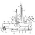
도 1은 본 발명의 바람직한 일 실시예에 따른 금융자동화기기의 지폐류 저장장치의 대기모드의 상태를 나타내는 저면에서 본 개략 사시도이고, 도 2는 수납모드의 상태로서, 푸쉬 플레이트가 생략되고, 투입구내의 일측 개폐판을 나타내는 저면에서 본 개략 사시도이고, 도 3은 도 1의 평면도이다.FIG. 1 is a schematic perspective view of a paper currency storage device of a banking automation apparatus according to a preferred embodiment of the present invention, viewed from a bottom surface showing a state of a standby mode, FIG. 2 is a state of a storage mode, Fig. 3 is a plan view of Fig. 1. Fig.
도 1 및 도 2에 도시된 바와 같이, 본 발명의 바람직한 일 실시예에 따른 금융자동화기기의 지폐류 저장장치에 있어서, 상기 금융자동화기기에 입금된 지폐류(4)가 수직으로 투입되는 투입구(10)와, 상기 투입구(10)로 투입되는 지폐류의 측면부위 양면을 지지하는 한 쌍의 개폐판(14)(16)과, 상기 투입구(10)를 중심으로 구획되는 제 1 및 제 2 저장부(20)(22)와, 상기 지폐류(4)가 투입되는 쪽의 저장부를 향하여 선택적으로 스트로크 작동하도록 상기 투입구(10)내에 위치되는 푸쉬바(30)(도 2)와, 상기 푸쉬바(30)의 스트로크 작동을 실행하는 푸쉬바 이송수단과, 상기 투입구(10)를 향하여 압력을 가하여 상기 푸쉬바(30)의 스트로크 작동에 의해 저장된 지폐류를 수직지지하는 한쌍의 푸쉬 플레이트(60)(62)를 포함한다.As shown in FIGS. 1 and 2, in a banknote storing device for a banknote automation apparatus according to a preferred embodiment of the present invention, banknotes 4 deposited in the automated teller machine are inserted vertically A pair of opening and
본 발명의 지폐류 저장장치는 그 본체(2)가 직육면체의 박스형상으로, 그 내부에는 투입구(10)가 격벽과 같이 수직으로 고정설치되며, 이 투입구(10)를 중심으로 제 1 및 제 2 저장부(20)(22)가 좌우로 나누어지며, ATM내에 입금된 지폐류(4)(도 1에서 점선으로 도시)는 수평으로 반송되어 투입구(10)의 상부에서 투입구(10)로 수직으로 투입된다. 또한 투입구(10) 양측의 한쌍의 푸쉬 플레이트(60)(62)는 푸쉬바(30)의 스트로크 작동에 의해 투입구(10)의 좌우로 슬라이딩 되어 벌어졌다가 다시 투입구(10)를 향하여 압력을 가하도록 설치된다.The banknote storage device of the present invention is characterized in that the
통상 ATM에 입금된 지폐류(4)는 ATM 내부의 반송로를 거치면서 그 크기와종류 등이 인식됨에 따라 저장하고자하는 저장부(20)(22)를 미리 설정할 수 있으므로, 이를 본 발명의 지폐류 저장장치에서 저장부(20)(22)가 좌우로 나누어지는 구성에 적용하면, 금융자동화기기에 입금된 지폐류를 미리 설정된 저장부에 선택적으로 수납할 수 있는 선택스택기능을 수행할 수 있다. 도면에 있어서, 좌측의 제 1 저장부(20)의 공간보다 우측의 제 2 저장부(22)의 공간이 헐씬 크지만, ATM의 운영상 그 크기를 조절할 수 있음은 물론이다.The banknotes 4 normally deposited in the ATM can be preset in the
도 3으로 부터 알 수 있는 바와 같이, 본체(2)의 바닥(6)에는 가이드홈(8)이 형성되고, 이 가이드홈(8)의 중간에 소정 폭(L)의 개방부(12)가 제공된 투입구(10)가 직교하여 개방부(12)와 가이드홈(8)이 연통된다. 또한 가이드홈(8)에는 푸쉬바(30)의 하부에 부착된 프랜지부(32)가 삽입되고, 푸쉬바(30)는 대기상태에서 투입구(10)의 개방부(12)를 폐쇄하도록 개방부(12)에 위치되어 좌우로 스트로크 작동된다. 이때, 푸쉬바(30)는 개방부(12)를 용이하게 통과할 수 있으면서도 투입된 지폐류(4)를 용이하게 저장부측으로 밀어넣을 수 있는 정도의 폭을 가지는 것이 바람직하다.3, a guide groove 8 is formed in the
또한, 도 2 및 도 3에 도시된 바와 같이, 투입구(10)에 설치된 한쌍의 개폐판(14)(16)은 투입구(10)로 투입되는 지폐류의 측면부위 양면을 지지한다. 이와 같 이 지폐류는 투입구(10)로 투입되어 개폐판(14)(16)에 의해 수직지지된 상태에서 저장하고자 하는 일측의 개폐판이 후퇴하면 지폐류는 프리한 상태, 즉 지지되지 않은 상태가 되므로 푸쉬바(30)의 작은 스크로크에 의해서도 저장동작이 가능하게 된다. 이 결과 저장공간을 확대시키는 효과가 있다.2 and 3, a pair of open /
또한, 예를 들어 투입구(10)의 개방부(12)에 위치되는 비교적 작은 크기의 지폐류(4)를 제 2 저장부(22)에 저장하는 경우에는 개방부(12)의 폭이 정해져 있으므로, 푸쉬바(30)의 우측 스트로크를 적게 설정하더라도 용이하게 제 2 저장부(22)로 밀어넣을 수 있지만, 좀 더 큰 크기의 지폐류(4)를 동일한 폭의 개방부(12)를 통해서 밀어넣는 것은 용이하지 않으므로, 동일한 폭의 개방부에서 지폐류(4)의 크기에 관계없이 저장부로 용이하게 밀어넣으려면 푸쉬바(30)의 스트로크를 길게 해야 하지만, 이는 저장장치의 크기가 커지게 되어 기기의 콤팩트화을 달성할 수 없게 된다. 이에 따라 본 발명의 지폐류 저장장치는 푸쉬바(30)가 가이드홈(8)을 따라 적게 설정된 스트로크로 이송되더라도, 푸쉬바(30)의 좌우 스트로크 작동과 연동되어 개폐판(14)(16)이 후퇴되어 개방부(12)를 좀더 개방하게 됨으로서, 제 1 및 제 2 저장부(20)(22)로 지폐류를 용이하게 밀어넣을 수 있게 된다.In addition, for example, when storing the relatively small size paper currency 4 located in the opening 12 of the
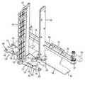
이와 같은 푸쉬바(30)의 스트로크 작동은 슬라이딩 부재(40)의 슬라이딩을 실행하는 푸쉬바 구동모터(50)로 이루어진 푸쉬바 이송수단에 의해 실행된다.The stroke operation of the
도 4 내지 도 6로부터 잘 알 수 있는 바와 같이, 슬라이딩부재(40)는 푸쉬바(30)의 하부에 부착되어 가이드홈(8)에 삽입되는 프랜지부(32)와 나사결합되며, 그 전면의 사각돌출부(42)는 본체(2)의 바닥에 평행하게 설치된 가이드돌기(3)들에 가이드되는 한편, 그 일측의 결합부(44)는 구동풀리(55)에 감긴 구동벨트(56)와 결합되고 가이드봉(58)에 삽입되어 구동벨트(56)의 회전에 따라 가이드봉(58)을 따라 슬라이딩된다. 구동풀리(55)의 일측에는 푸쉬바 구동모터(50)의 축에 연결된 베벨기어(57)가 부착되어, 구동모터(40)의 정역회전에 따라 구동벨트(56)가 정역회전하게 되고, 이에 슬라이딩부재(40)는 좌우로 슬라이딩되므로 푸쉬바(30)가 좌우로 스트로크 작동된다.4 to 6, the sliding
한편 본 발명의 지폐류 저장장치는 도 1및 도 2에 도시된 바와 같이, 투입구(10)의 하부에 한쌍의 가이드 슬릿(17)(18)이 형성되고, 이 가이드 슬릿(17)(18)의 각각에 개폐판(14)(16)의 각각이 삽입되고 그 하부에 체결판(34)이 나사결합되어 부착된다. 슬라이딩부재(40)에는 베어링돌기(46)가 중앙에 제공되며, 이 베어링돌기(46)를 중심으로 서로 대향하는 한쌍의 제 1 회동부재(70)(72)가 설치된다. 제 1 회동부재(70)(72)의 각각은 "ㄱ"자 형상으로, 제 1 힌지축(73)을 기준으로 수직부(74)와 수평부분에 형성된 볼록부(76)로 구성된다. 볼록부(76)는 일측의 돌기(77)부터 소정의 기울기를 가지는 경사면(78)과 이 경사면(78)에 이어진 만곡면(79)으로 구성된다.1 and 2, a pair of
또한, 제 1 회동부재(70)(72) 각각의 회동과 연동하여 한 쌍의 제 2 회동부재(80)(82)의 각각이 회동된다. 제 2 회동부재(80)(82)의 각각은 그 중앙에 회동핀(84)이 하향돌출되어 있고, 그 일단은 개폐판(14)(16)의 각각의 하면에 부착된 체결판(34)과 나사결합되고, 타단은 제 2 힌지축(88)이 삽입되는 오목홈(86)이 형성된다. 각 제 2 회동부재(80)(82) 중앙의 회동핀(84)은 대기상태에서는 제 1 회동 부재(70)(72)의 각각의 볼록부(76)의 돌기(77)와 접하고 있으나, 회동상태에서는 제 1 회동부재(70)(72) 각각의 경사면(78)으로부터 만곡면(79)으로 이동되어 위치된다.In addition, each of the pair of second
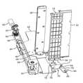
도 7에 도시된 바와 같이 푸쉬바(30)가 제 2 저장부(22)를 향하여 스트로크작동되면, 슬라이딩부재(40)도 도 2에서 우측으로, 즉 제 2 저장부(22)를 향하여 슬라이딩된다. 이때 슬라이딩부재(40)에 제공된 베어링돌기(46)가 제 1 회동부재(72)의 수직부(74)를 밀게되고, 이에 의해 제 2 회동부재(72)는 제 1 힌지축(73)을 중심으로 반시계방향으로 회동하게 된다.7, when the
비록 구체적으로 도시하지는 않았지만, 이와 반대로 슬라이딩부재(40)가 좌측으로, 즉 제 1 저장부(20)쪽으로 슬라이딩되면, 상기와 마찬가지로 슬라이딩부재(40)에 제공된 베어링돌기(46)가 제 1 회동부재(70)의 수직부(74)를 밀게되고, 이에 의해 제 1 회동부재(70)는 제 1 힌지축(73)을 중심으로 시계방향으로 회동하게 된다.When the sliding
이상과 같이 제 1 회동부재(72)가 반시계방향으로 회동하면, 제 1 회동부재(72)의 볼록부(76)의 돌기(77)에 접하고 있던 제 2 회동부재(82) 중앙의 회동핀(84)은 제 1 회동부재(72)의 볼록부(76)의 경사면(78)에서 만곡면(79)에 위치하도록 이동하게 되므로, 제 2 회동부재(82)는 제 2 힌지축(88)을 중심으로 시계방향으로 회동한다. 이와 동시에 제 2 회동부재(82)의 일단과 나사결합된 개폐판(16) 하부의 체결판(34)이 투입구(10)의 가이드 슬릿(18)을 따라 이동됨으로서 개폐판(16)이 투입구(10)에서 전진 및 후퇴된다.When the first
또한 이상과 마찬가지로, 제 1 회동부재(70)가 시계방향으로 회동되면, 제 1 회동부재(70)에 연동되는 제 2 회동부재(80)는 반시계방향으로 회동되어 개폐판(14)이 투입구(10)에서 전진 및 후퇴된다.When the first
이상과 같이 구성된 본 발명의 금융자동화기기의 지폐류 저장장치는 지폐류를 다음과 같이 저장한다.The paper currency storage device of the present invention having the above-described configuration stores paper money as follows.
금융자동화기기에 지폐류가 입금되면, 기기내부의 반송로를 통해 반송하면서 예를 들어 인식모듈에 의해 지폐류의 종류와 크기를 인식하게 되고, 이에 따라 제 1 및 제 2 저장부(20)(22)의 어느 하나의 저장부에 저장할 것인지를 미리 결정한다.When the banknotes are deposited in the automated teller machine, the recognition module recognizes the type and size of banknotes while the banknote is conveyed through the conveying path inside the apparatus. Thus, the first and second storage units 20 22 in the storage unit.
이 결정에 따라 푸쉬바(30)는 설정된 저장부측으로 지폐류를 푸쉬할 수 있도록 지폐류 투입 전 미리 소정위치에 위치된다.According to this determination, the
이어서, 투입구(10)를 통해 입금 지폐류가 미리 설정된 저장부를 향하여 수직으로 투입한다. 예를 들어 입금 지폐류(4)를 제 2 저장부(22)에 저장하고자 하면, 투입구(10)를 통해 수직 투입된 지폐류는 푸쉬바(30)와 제 2 저장부(22)사이의 투입부(10)의 개방부(12)에 위치된다.Then, the deposited banknotes are fed vertically through the
이어서, 구동모터(50)는 푸쉬바(30)가 제 2 저장부(22)로 스트로크 작동하도록 구동하여 구동벨트(56)를 정역회전한다. 이에 따라 슬라이딩부재(40)가 제 2 저장부(22)를 향하여 슬라이딩되고, 슬라이딩부재(40) 중앙의 베어링돌기(46)는 제 1 회동부재(72)의 수직부(74)를 밀게된다. 그 결과 제 1 회동부재(72)는 제 1 힌지축(73)을 중심으로 반시계방향으로 회동하고, 이에 연동하여 제 2 회동부재(82)은 제 2 힌지축(88)을 중심으로 시계방향으로 회동하고, 투입구 개폐판(16)이 개방된다.Then, the
이와 같이 본 발명의 지폐류 저장장치는 푸쉬바(30)의 제 2 저장부(22)로의 스트로크 동작에 연동하여 투입구 개폐판(16)이 투입구(10)내로 수축되므로, 푸쉬바(30)의 스트로크 작동에 의해 투입구(10)의 개방부(12)를 통과하는 지폐류(4)가 용이하게 제 2 저장부(22)로 밀어넣어지게 되고, 동시에 밀어넣어진 지폐류(4)는 푸쉬 플레이트(62)에 의해 투입구(10)를 향하여 압력이 가해지므로 투입구(10)와 푸쉬 플레이트(62)사이에서 수직 저장된다.As described above, in the paper currency storage device of the present invention, the inlet opening /
이상에서 설명한 것은 본 발명에 따른 금융자동화기기의 지폐류 저장장치 및 저장방법의 바람직한 실시예에 불과한 것으로서, 본 발명은 상기한 실시예에 한정되지 않는 것으로, 예를 들어 이상의 실시예에서는 푸쉬바와 개폐판이 링크수단에 의해 하나의 구동원으로 작동될 수도 있으나, 각각 별개의 구동원에 의해 작동될 수도 있으므로, 이하의 특허청구범위에서 청구하는 바와 같이 본 발명의 요지를 벗어남이 없이 당해 발명이 속하는 분야에서 통상의 지식을 가진 자라면 누구든지 다양한 변경 실시가 가능한 범위까지 본 발명의 기술적 정신이 있다고 할 것이다.The above description is only a preferred embodiment of the paper money storing and storing method of the financial automatic machine according to the present invention. The present invention is not limited to the above-described embodiments. For example, The plates may be operated as a single drive source by the link means but may be operated by separate drive sources so that the present invention is not limited to the above- It will be understood by those of ordinary skill in the art that various changes in form and details may be made therein without departing from the spirit and scope of the invention.
도 1은 본 발명의 바람직한 일 실시예에 따른 금융자동화기기의 지폐류 저장장치의 대기모드의 상태를 나타내는 저면에서 본 개략 사시도이고,1 is a schematic perspective view of a paper currency storage device of a financial automatic machine according to a preferred embodiment of the present invention,
도 2는 도 1 저장장치의 수납모드의 상태로서, 푸쉬 플레이트가 생략되고, 투입구내의 일측 개폐판을 나타내는 저면에서 본 개략 사시도이고,Fig. 2 is a schematic perspective view of the storage mode of the storage device of Fig. 1, viewed from the bottom showing the one opening / closing plate in the charging port,
도 3은 도 1의 평면도이고,Fig. 3 is a plan view of Fig. 1,
도 4는 도 2의 "A"에서 본 개략 사시도이고,4 is a schematic perspective view seen from "A" in Fig. 2,
도 5은 도 2의 "B"에서 본 개략 사시도이고,5 is a schematic perspective view seen from "B" in Fig. 2,
도 6은 도 2의 "C"에서 본 개략 사시도이고,Fig. 6 is a schematic perspective view seen from "C" in Fig. 2,
도 7은 도 2의 평면도이다.Fig. 7 is a plan view of Fig. 2. Fig.
<도면의 주요부분에 대한 부호의 설명>Description of the Related Art
2 : 저장장치 본체 3 : 가이드돌기2: Storage device body 3: Guide protrusion
4 : 지폐류 6 : 바닥4: paper money 6: bottom
8 : 가이드홈 10 : 투입구8: guide groove 10: inlet
12 : 개방부 14,16 : 개폐판12: opening
17,18 : 가이드 슬릿 20 : 제 1 저장부17, 18: Guide slit 20: First storage part
22 : 제 2 저장부 30 : 푸쉬바22: second storage unit 30: push bar
32 : 프랜지부 34 : 체결판32: flange portion 34: fastening plate
40 : 슬라이딩부재 42 ; 사각돌출부40: sliding
44 : 결합부 46 : 베어링돌기44: engaging portion 46: bearing projection
50 : 푸쉬바 구동모터 55 : 구동풀리50: push bar drive motor 55: drive pulley
56 : 구동벨트 57 : 베벨기어56: drive belt 57: bevel gear
58 : 가이드봉 60,62 : 푸쉬 플레이트58: guide
70,72 : 제 1 회동부재 73 : 제 1 힌지축70, 72: first rotating member 73: first hinge shaft
74 : 수직부 76 : 볼록부74: vertical part 76: convex part
77 : 돌기 78 : 경사면77: projection 78: inclined surface
79 : 만곡면 80,82 : 제 2 회동부재79:
84 : 회동핀 86 : 오목홈84: pivot pin 86: concave groove
88 : 제 2 힌지축 90 : 스프링88: second hinge shaft 90: spring
Claims (5)
Translated fromKoreanPriority Applications (2)
| Application Number | Priority Date | Filing Date | Title |
|---|---|---|---|
| KR1020080088870AKR101035563B1 (en) | 2008-09-09 | 2008-09-09 | Paper money storage and method of financial automation equipment |
| US12/555,615US7913830B2 (en) | 2008-09-09 | 2009-09-08 | Bill storage device in automated teller machine and method for storing bill in the same |
Applications Claiming Priority (1)
| Application Number | Priority Date | Filing Date | Title |
|---|---|---|---|
| KR1020080088870AKR101035563B1 (en) | 2008-09-09 | 2008-09-09 | Paper money storage and method of financial automation equipment |
Publications (2)
| Publication Number | Publication Date |
|---|---|
| KR20100030089A KR20100030089A (en) | 2010-03-18 |
| KR101035563B1true KR101035563B1 (en) | 2011-05-19 |
Family
ID=41798285
Family Applications (1)
| Application Number | Title | Priority Date | Filing Date |
|---|---|---|---|
| KR1020080088870AExpired - Fee RelatedKR101035563B1 (en) | 2008-09-09 | 2008-09-09 | Paper money storage and method of financial automation equipment |
Country Status (2)
| Country | Link |
|---|---|
| US (1) | US7913830B2 (en) |
| KR (1) | KR101035563B1 (en) |
Families Citing this family (4)
| Publication number | Priority date | Publication date | Assignee | Title |
|---|---|---|---|---|
| KR101094499B1 (en) | 2010-08-03 | 2011-12-20 | 엘지엔시스(주) | Financial Automation Equipment |
| TWI456529B (en)* | 2011-07-26 | 2014-10-11 | 日立歐姆龍金融系統有限公司 | Paper sheet processing device |
| JP6243555B2 (en)* | 2015-01-09 | 2017-12-06 | 富士通フロンテック株式会社 | Paper sheet storage device and paper sheet storage method |
| US11055679B2 (en)* | 2016-04-20 | 2021-07-06 | Ncr Corporation | Bunch document recycler |
Citations (3)
| Publication number | Priority date | Publication date | Assignee | Title |
|---|---|---|---|---|
| KR19980037295A (en)* | 1996-11-21 | 1998-08-05 | 배순훈 | Ticket vending machine bill storage device |
| JP2002163702A (en) | 2000-11-22 | 2002-06-07 | Fuji Electric Co Ltd | Banknote storage device of banknote recognition machine |
| JP2002203265A (en) | 2000-12-28 | 2002-07-19 | Glory Ltd | Coin receiving machine |
Family Cites Families (1)
| Publication number | Priority date | Publication date | Assignee | Title |
|---|---|---|---|---|
| US6588569B1 (en)* | 2000-02-11 | 2003-07-08 | Cummins-Allison Corp. | Currency handling system having multiple output receptacles |
- 2008
- 2008-09-09KRKR1020080088870Apatent/KR101035563B1/ennot_activeExpired - Fee Related
- 2009
- 2009-09-08USUS12/555,615patent/US7913830B2/ennot_activeExpired - Fee Related
Patent Citations (3)
| Publication number | Priority date | Publication date | Assignee | Title |
|---|---|---|---|---|
| KR19980037295A (en)* | 1996-11-21 | 1998-08-05 | 배순훈 | Ticket vending machine bill storage device |
| JP2002163702A (en) | 2000-11-22 | 2002-06-07 | Fuji Electric Co Ltd | Banknote storage device of banknote recognition machine |
| JP2002203265A (en) | 2000-12-28 | 2002-07-19 | Glory Ltd | Coin receiving machine |
Also Published As
| Publication number | Publication date |
|---|---|
| US20100059417A1 (en) | 2010-03-11 |
| US7913830B2 (en) | 2011-03-29 |
| KR20100030089A (en) | 2010-03-18 |
Similar Documents
| Publication | Publication Date | Title |
|---|---|---|
| KR101923700B1 (en) | Connectable banknote receiver - Automatic financial transaction terminal with presenter | |
| KR101089655B1 (en) | Paper sheet handling device | |
| KR20140009487A (en) | Bill storage box and bill handling device | |
| JP6303921B2 (en) | Media transaction equipment | |
| US20170103621A1 (en) | Automated transaction machine with articulated note acceptor-presenter | |
| KR101035563B1 (en) | Paper money storage and method of financial automation equipment | |
| US10769878B2 (en) | Fascia gate separable gear drive | |
| US10994955B2 (en) | Tray unit assembly | |
| KR101548308B1 (en) | Apparatus for extracting paper money so on storaged in an atm and method therefor | |
| KR100526583B1 (en) | paper money deposit device in auto teller machine | |
| KR102002948B1 (en) | Media transfer module and financial device thereof | |
| KR101016245B1 (en) | Withdrawal device of automatic teller machine | |
| KR200392317Y1 (en) | Apparatus of drawing bills in a cash transaction machine | |
| KR101687107B1 (en) | Media deposition apparatus | |
| CN106056755B (en) | Bill handling device and automatic trading apparatus | |
| KR101099900B1 (en) | Withdrawal device of automatic teller machine | |
| KR100576911B1 (en) | Plate moving device for recycling box of banknote machine | |
| KR20050071235A (en) | Plate locker of the auto teller machine recycle-box | |
| JP7226098B2 (en) | Media processing device and media trading device | |
| KR20060042596A (en) | Banknote storage device of automatic teller machine | |
| KR101016494B1 (en) | Withdrawal device of automatic teller machine | |
| KR101799393B1 (en) | Media process apparatus and financial device thereof | |
| KR20230171511A (en) | Automated Teller Machine | |
| JP2016057687A (en) | Medium processor | |
| KR101016508B1 (en) | Withdrawal device of automatic teller machine |
Legal Events
| Date | Code | Title | Description |
|---|---|---|---|
| A201 | Request for examination | ||
| PA0109 | Patent application | St.27 status event code:A-0-1-A10-A12-nap-PA0109 | |
| PA0201 | Request for examination | St.27 status event code:A-1-2-D10-D11-exm-PA0201 | |
| PG1501 | Laying open of application | St.27 status event code:A-1-1-Q10-Q12-nap-PG1501 | |
| D13-X000 | Search requested | St.27 status event code:A-1-2-D10-D13-srh-X000 | |
| D14-X000 | Search report completed | St.27 status event code:A-1-2-D10-D14-srh-X000 | |
| E902 | Notification of reason for refusal | ||
| PE0902 | Notice of grounds for rejection | St.27 status event code:A-1-2-D10-D21-exm-PE0902 | |
| P11-X000 | Amendment of application requested | St.27 status event code:A-2-2-P10-P11-nap-X000 | |
| P13-X000 | Application amended | St.27 status event code:A-2-2-P10-P13-nap-X000 | |
| R17-X000 | Change to representative recorded | St.27 status event code:A-3-3-R10-R17-oth-X000 | |
| E701 | Decision to grant or registration of patent right | ||
| PE0701 | Decision of registration | St.27 status event code:A-1-2-D10-D22-exm-PE0701 | |
| GRNT | Written decision to grant | ||
| PR0701 | Registration of establishment | St.27 status event code:A-2-4-F10-F11-exm-PR0701 | |
| PR1002 | Payment of registration fee | St.27 status event code:A-2-2-U10-U11-oth-PR1002 Fee payment year number:1 | |
| PG1601 | Publication of registration | St.27 status event code:A-4-4-Q10-Q13-nap-PG1601 | |
| R18-X000 | Changes to party contact information recorded | St.27 status event code:A-5-5-R10-R18-oth-X000 | |
| FPAY | Annual fee payment | Payment date:20131218 Year of fee payment:4 | |
| PR1001 | Payment of annual fee | St.27 status event code:A-4-4-U10-U11-oth-PR1001 Fee payment year number:4 | |
| FPAY | Annual fee payment | Payment date:20150504 Year of fee payment:5 | |
| PR1001 | Payment of annual fee | St.27 status event code:A-4-4-U10-U11-oth-PR1001 Fee payment year number:5 | |
| FPAY | Annual fee payment | Payment date:20160512 Year of fee payment:6 | |
| PR1001 | Payment of annual fee | St.27 status event code:A-4-4-U10-U11-oth-PR1001 Fee payment year number:6 | |
| P22-X000 | Classification modified | St.27 status event code:A-4-4-P10-P22-nap-X000 | |
| FPAY | Annual fee payment | Payment date:20170426 Year of fee payment:7 | |
| PR1001 | Payment of annual fee | St.27 status event code:A-4-4-U10-U11-oth-PR1001 Fee payment year number:7 | |
| P22-X000 | Classification modified | St.27 status event code:A-4-4-P10-P22-nap-X000 | |
| PN2301 | Change of applicant | St.27 status event code:A-5-5-R10-R13-asn-PN2301 St.27 status event code:A-5-5-R10-R11-asn-PN2301 | |
| PR1001 | Payment of annual fee | St.27 status event code:A-4-4-U10-U11-oth-PR1001 Fee payment year number:8 | |
| FPAY | Annual fee payment | Payment date:20190430 Year of fee payment:9 | |
| PR1001 | Payment of annual fee | St.27 status event code:A-4-4-U10-U11-oth-PR1001 Fee payment year number:9 | |
| PR1001 | Payment of annual fee | St.27 status event code:A-4-4-U10-U11-oth-PR1001 Fee payment year number:10 | |
| PR1001 | Payment of annual fee | St.27 status event code:A-4-4-U10-U11-oth-PR1001 Fee payment year number:11 | |
| PR1001 | Payment of annual fee | St.27 status event code:A-4-4-U10-U11-oth-PR1001 Fee payment year number:12 | |
| R18-X000 | Changes to party contact information recorded | St.27 status event code:A-5-5-R10-R18-oth-X000 | |
| PC1903 | Unpaid annual fee | St.27 status event code:A-4-4-U10-U13-oth-PC1903 Not in force date:20230513 Payment event data comment text:Termination Category : DEFAULT_OF_REGISTRATION_FEE | |
| PC1903 | Unpaid annual fee | St.27 status event code:N-4-6-H10-H13-oth-PC1903 Ip right cessation event data comment text:Termination Category : DEFAULT_OF_REGISTRATION_FEE Not in force date:20230513 |