KR101033132B1 - Hybrid Fluid Level Measuring Device - Google Patents
Hybrid Fluid Level Measuring DeviceDownload PDFInfo
- Publication number
- KR101033132B1 KR101033132B1KR1020100067496AKR20100067496AKR101033132B1KR 101033132 B1KR101033132 B1KR 101033132B1KR 1020100067496 AKR1020100067496 AKR 1020100067496AKR 20100067496 AKR20100067496 AKR 20100067496AKR 101033132 B1KR101033132 B1KR 101033132B1
- Authority
- KR
- South Korea
- Prior art keywords
- chamber
- gauge
- pressure
- air
- fluid level
- Prior art date
- Legal status (The legal status is an assumption and is not a legal conclusion. Google has not performed a legal analysis and makes no representation as to the accuracy of the status listed.)
- Active
Links
Images


Classifications
- G—PHYSICS
- G01—MEASURING; TESTING
- G01F—MEASURING VOLUME, VOLUME FLOW, MASS FLOW OR LIQUID LEVEL; METERING BY VOLUME
- G01F23/00—Indicating or measuring liquid level or level of fluent solid material, e.g. indicating in terms of volume or indicating by means of an alarm
- G01F23/22—Indicating or measuring liquid level or level of fluent solid material, e.g. indicating in terms of volume or indicating by means of an alarm by measuring physical variables, other than linear dimensions, pressure or weight, dependent on the level to be measured, e.g. by difference of heat transfer of steam or water
- G—PHYSICS
- G01—MEASURING; TESTING
- G01D—MEASURING NOT SPECIALLY ADAPTED FOR A SPECIFIC VARIABLE; ARRANGEMENTS FOR MEASURING TWO OR MORE VARIABLES NOT COVERED IN A SINGLE OTHER SUBCLASS; TARIFF METERING APPARATUS; MEASURING OR TESTING NOT OTHERWISE PROVIDED FOR
- G01D11/00—Component parts of measuring arrangements not specially adapted for a specific variable
- G01D11/16—Elements for restraining, or preventing the movement of, parts, e.g. for zeroising
- G01D11/18—Springs
- G—PHYSICS
- G01—MEASURING; TESTING
- G01D—MEASURING NOT SPECIALLY ADAPTED FOR A SPECIFIC VARIABLE; ARRANGEMENTS FOR MEASURING TWO OR MORE VARIABLES NOT COVERED IN A SINGLE OTHER SUBCLASS; TARIFF METERING APPARATUS; MEASURING OR TESTING NOT OTHERWISE PROVIDED FOR
- G01D11/00—Component parts of measuring arrangements not specially adapted for a specific variable
- G01D11/24—Housings ; Casings for instruments
- G01D11/245—Housings for sensors
- G—PHYSICS
- G01—MEASURING; TESTING
- G01D—MEASURING NOT SPECIALLY ADAPTED FOR A SPECIFIC VARIABLE; ARRANGEMENTS FOR MEASURING TWO OR MORE VARIABLES NOT COVERED IN A SINGLE OTHER SUBCLASS; TARIFF METERING APPARATUS; MEASURING OR TESTING NOT OTHERWISE PROVIDED FOR
- G01D13/00—Component parts of indicators for measuring arrangements not specially adapted for a specific variable
- G01D13/02—Scales; Dials
- G—PHYSICS
- G01—MEASURING; TESTING
- G01L—MEASURING FORCE, STRESS, TORQUE, WORK, MECHANICAL POWER, MECHANICAL EFFICIENCY, OR FLUID PRESSURE
- G01L19/00—Details of, or accessories for, apparatus for measuring steady or quasi-steady pressure of a fluent medium insofar as such details or accessories are not special to particular types of pressure gauges
- G01L19/06—Means for preventing overload or deleterious influence of the measured medium on the measuring device or vice versa
- G—PHYSICS
- G01—MEASURING; TESTING
- G01L—MEASURING FORCE, STRESS, TORQUE, WORK, MECHANICAL POWER, MECHANICAL EFFICIENCY, OR FLUID PRESSURE
- G01L19/00—Details of, or accessories for, apparatus for measuring steady or quasi-steady pressure of a fluent medium insofar as such details or accessories are not special to particular types of pressure gauges
- G01L19/08—Means for indicating or recording, e.g. for remote indication
Landscapes
- Physics & Mathematics (AREA)
- General Physics & Mathematics (AREA)
- Thermal Sciences (AREA)
- Fluid Mechanics (AREA)
- Measuring Volume Flow (AREA)
Abstract
Translated fromKoreanDescription
Translated fromKorean본 발명은 복합형 유체 레벨 측정 장치에 관한 것으로, 더욱 상세하게는, 각종 유체 탱크의 레벨을 측정하는데 컴팩트하게 일체형으로, 보다 좁은 공간에 간단히 설치할 수 있는 복합형 유체 레벨 측정 장치로서, 공기 공급 장치로부터 압축 공기를 인가받아 안정된 기체압의 공기를 상기 탱크로 발생시키는 공기조절장치부; 상기 탱크 내의 유체의 수두압에 대한 배압을 표시하는 지시계; 하나 이상의 내부관로를 포함하여 이루어지되, 상기 유체의 수두압에 대한 배압을 지시계로 전달하는 전달부; 및 상기 공기조절장치부의 상부에 마련되어, 이상 압력 발생시 상기 지시계로의 내부관로를 차단하는 게이지 세이버부를 포함하여 이루어지는 복합형 유체 레벨 측정 장치에 관한 것이다.
The present invention relates to a complex fluid level measuring device, and more particularly, to a complex fluid level measuring device which can be easily installed in a narrower space in a compact integrated type for measuring the level of various fluid tanks, An air conditioning unit that receives compressed air from the air and generates stable gas pressure air into the tank; An indicator indicating a back pressure relative to the head pressure of the fluid in the tank; A transmission unit including one or more inner pipes and transmitting a back pressure to the indicator of the head pressure of the fluid; And a gauge saver unit provided on an upper portion of the air conditioner unit to block an internal passage to the indicator when an abnormal pressure is generated.
일반적으로 유량 레벨측정기는 탱크 속에 저장된 유체의 수위를 측정하는데 사용되는데, 도 1 에는 이러한 공압 모듈레이터(10)를 포함하는 에어퍼지타입 레벨 게이징 시스템이 도시되어 있다. 공압 모듈레이터(10)의 작동을 살펴보면, 공기주입구(12)를 통해 공기공급장치(30)로부터 공기를 공급받고, 이 때, 주입된 공기 중 탱크(40)의 수위에 해당하는 공기만 배관(16) 내에 남아 배압으로 작용하게 된다. 즉, 배관(16)에는 유체에 접속된 파이프 밑단에서 액체 높이에 대한 수두압이 생성되며, 수두압 이상의 압력은 배관(16)의 끝에서 공기방울로 배출된다. 상기 배관(16) 내의 배압은 게이지 세이버(20)를 통해 유압 지시계(50)에 레벨로 표시되거나 배압을 전기 신호로 변환하는 P/I 컨버터(70)를 거쳐 전자 지시계(60)에 표시되고 중앙 컨트롤 장치로 신호 전송되기도 한다. 또한, 유체 탱크 내의 이상 압력으로 인한 각종 센서 및 계기류의 파손을 막기 위해 게이지 세이버를 설치한다.
Generally, a flow level meter is used to measure the level of fluid stored in a tank, which is shown in FIG. 1 by an air purge type level gauging system including such a
그러나, 상기와 같은 레벨 게이징 시스템은 공압 모듈레이터, 게이지 세이버부, 및 신호 출력 장치 등을 별도의 장치로 구비해야 하므로, 전체 장치가 대용량으로 될 수 밖에 없고 이들 구성을 연결함에 있어서도 설비가 복잡해지는 문제점이 있다.
However, the level gauging system as described above should be provided with a separate device such as a pneumatic modulator, a gauge saver unit, and a signal output device, so that the entire device becomes large in capacity and the equipment becomes complicated in connecting these configurations. There is a problem.
또한, 부품 개수의 증가로 인해 제작비용이 증가할 뿐만 아니라, 제작 및 설비 공정이 다단계로 이루어짐으로 인해 작업이 번거로워 기타 작업상의 불편함도 많다.
In addition, the production cost increases due to the increase in the number of parts, and the work is cumbersome due to the multi-step manufacturing and installation process, and there are many inconveniences in other operations.
따라서, 본 발명은 상기와 같은 종래 기술의 문제점을 해결하기 위해서 안출한 것으로서, 유체 레벨 측정 기능, 게이지 세이버, 지시계 기능을 포함한 복합 기능을 컴팩트한 장치로 통합적으로 제공하고, 일체화를 통해 부품의 개수를 현저히 줄이고, 소형화로 인해 설치 공간을 줄일 수 있는 복합형 유체 레벨 측정 장치를 제공하고자 한다.
Accordingly, the present invention has been made to solve the problems of the prior art as described above, and provides a complex device including a fluid level measurement function, gauge saver, indicator function integrated into a compact device, the number of parts through integration It is to provide a complex fluid level measurement device that can significantly reduce the size and the installation space due to the miniaturization.
또한, 구조가 간단하여 비용을 절감할 수 있고, 제작 공정상의 편의 또한 도모할 수 있으며, 이상 압력 발생으로 인한 장치 파손 등의 문제를 해결하여 내구성을 향상시킬 수 있는 복합형 유체 레벨 측정 장치를 제공하고자 한다.
In addition, the structure is simple to reduce costs, to facilitate the manufacturing process, and to provide a complex fluid level measurement device that can improve the durability by solving problems such as damage to the device due to abnormal pressure generation. I would like to.
상술한 목적을 달성하기 위하여 본 발명의 일 실시형태에 따른 복합형 유체 레벨 측정 장치는, 탱크 내의 유체의 레벨을 측정하는 복합형 유체 레벨 측정 장치로서, 공기 공급 장치로부터 압축 공기를 인가받아 안정된 기체압의 공기를 상기 탱크로 발생시키는 공기조절장치부; 상기 탱크 내의 유체의 수두압에 대한 배압을 표시하는 지시계; 하나 이상의 내부관로를 포함하여 이루어지되, 상기 유체의 수두압에 대한 배압을 지시계로 전달하는 전달부; 및 상기 공기조절장치부의 상부에 마련되어, 이상 압력 발생시 상기 지시계로의 내부관로를 차단하는 게이지 세이버부를 포함하여 이루어지며, 상기 공기조절장치부는 유입된 압축 공기를 저장하는 제1챔버와, 상기 유체의 수두압에 대한 배압을 갖는 공기를 저장하는 제2챔버와, 상기 제1챔버와 상기 제2챔버 사이에 마련되되 상기 제1챔버와 상기 제2챔버의 압력차에 의해 개폐되는 릴리프밸브와, 상기 제2챔버와 제1내부관로를 통해 연결되되, 유량제어밸브에 접속되어 상기 유량제어밸브에 의해 제어된 유량의 공기를 저장하는 제3챔버를 포함하여 이루어지되, 상기 제3챔버는 제2내부관로를 통해 상기 탱크에 접속되는 것을 특징으로 한다.
In order to achieve the above object, the hybrid fluid level measuring device according to an embodiment of the present invention is a complex fluid level measuring device for measuring the level of a fluid in a tank, and is supplied with compressed air from an air supply device to stabilize gas. An air conditioner unit for generating pressure air to the tank; An indicator indicating a back pressure relative to the head pressure of the fluid in the tank; A transmission unit including one or more inner pipes and transmitting a back pressure to the indicator of the head pressure of the fluid; And a gauge saver portion provided on an upper portion of the air conditioner portion to block an internal passage to the indicator when an abnormal pressure occurs, wherein the air conditioner portion stores a first chamber for storing the compressed air introduced therein; A second chamber for storing air having a back pressure against the head pressure, a relief valve provided between the first chamber and the second chamber, the relief valve being opened and closed by a pressure difference between the first chamber and the second chamber, A third chamber connected to the second chamber and the first inner conduit, the third chamber being connected to the flow control valve and storing the air of the flow rate controlled by the flow control valve, wherein the third chamber has a second inner portion. It is characterized in that it is connected to the tank through a pipeline.
삭제delete
또한, 복합형 유체 레벨 측정 장치를 구성하는 게이지 세이버부는 게이지 세이버 하판, 게이지 세이버 다이아프램, 게이지 세이버 상판, 및 하부에 원판형 플레이트가 형성된 게이지 세이버 스풀을 포함하여 이루어지되, 상기 원판형 플레이트는 상기 제3챔버의 내부에 위치하여, 제3챔버 내의 압력변화에 의해 상하로 유동하는 것을 또 다른 특징으로 한다.
In addition, the gauge saver portion constituting the hybrid fluid level measuring device comprises a gauge saber bottom plate, a gauge saber diaphragm, a gauge saber top plate, and a gauge saber spool with a disc plate formed on the bottom thereof, wherein the disc plate is the disc plate. Located inside the third chamber, it is another feature that the flow up and down by the pressure change in the third chamber.
여기서, 공기조절장치부의 제3챔버는 제3내부관로를 통해 상기 지시계와 접속되며, 상기 제3챔버 상면에는 상기 제3내부관로의 일단 주위로 소정 깊이의 홈이 형성되고, 상기 홈 안에서 게이지 세이버 니플이 상기 제3내부관로의 일단에 결합되어, 상기 게이지 세이버 스풀의 상하 유동에 의해 상기 게이지 세이버 니플이 개폐되는 것을 또 다른 특징으로 할 수 있다.
Here, the third chamber of the air conditioner unit is connected to the indicator through a third inner conduit, and a groove having a predetermined depth is formed on one side of the third inner conduit on the upper surface of the third chamber, and the gauge saver in the groove. The nipple is coupled to one end of the third inner pipe, it may be another feature that the gauge saber nipple is opened and closed by the vertical flow of the gauge saber spool.
또한, 복합형 유체 레벨 측정 장치는, 공기조절장치부의 제1챔버와 상기 제2내부관로에 연통되는 블로우 밸브를 더 포함하고, 상기 블로우 밸브를 통해 공기를 주입함으로써 상기 유체 레벨 측정 장치 내의 이물질을 제거할 수 있는 것을 또 다른 특징으로 할 수 있다.
In addition, the hybrid fluid level measuring device further includes a blow valve in communication with the first chamber and the second internal conduit of the air conditioner unit, and injects air through the blow valve to remove foreign matter in the fluid level measuring device. It can be another feature that can be removed.
한편, 블로우 밸브를 통해 공기를 주입할 때, 상기 게이지 세이버 스풀이 상기 게이지 세이버 니플을 폐쇄하는 것을 또 다른 특징으로 할 수 있다.
On the other hand, when injecting air through the blow valve, it may be another feature that the gauge saber spool closes the gauge saber nipple.
또한, 상기 복합형 유체 레벨 측정 장치는 상기 제3내부관로에 연결되어 상기 제3챔버 내의 공기압을 센싱하는 압력 센서를 더 포함하며, 상기 압력 센서는 실리콘 튜브 패킹을 사용하여 내부에 결합되는 것을 또 다른 특징으로 한다.
In addition, the hybrid fluid level measuring device further comprises a pressure sensor connected to the third internal conduit for sensing the air pressure in the third chamber, the pressure sensor is further coupled to the inside using a silicon tube packing It is another feature.
그리고, 상기 복합형 유체 레벨 측정 장치는, 상기 게이지 세이버부에 접속되어, 상기 유체의 수두압을 측정하여 전기신호 또는 전자신호로 변환하는 신호출력장치를 더 포함할 수 있다.
The complex fluid level measurement device may further include a signal output device connected to the gauge saver unit and measuring the head pressure of the fluid and converting the head pressure into an electrical signal or an electronic signal.
이상에서 본 바와 같이, 본 발명에 따른 복합형 유체 레벨 측정 장치는 공기 공급 장치로부터 압축 공기를 인가받아 안정된 기체압의 공기를 상기 탱크로 발생시키는 공기조절장치부; 상기 탱크 내의 유체의 수두압에 대한 배압을 표시하는 지시계; 하나 이상의 내부관로를 포함하여 이루어지되, 상기 유체의 수두압에 대한 배압을 지시계로 전달하는 전달부; 및 상기 공기조절장치부의 상부에 마련되어, 이상 압력 발생시 상기 지시계로의 내부관로를 차단하는 게이지 세이버부를 포함하여 이루어짐으로써, 지시계와 신호출력 기능, 및 유량 레벨 측정 기능 등의 복합 기능을 컴팩트한 장치로서 통합적으로 제공할 수 있다.As seen above, the hybrid fluid level measuring apparatus according to the present invention is applied to the compressed air from the air supply unit air conditioning unit for generating a stable gas pressure air to the tank; An indicator indicating a back pressure relative to the head pressure of the fluid in the tank; A transmission unit including one or more inner pipes and transmitting a back pressure to the indicator of the head pressure of the fluid; And a gauge saver unit provided above the air conditioner unit to block an internal passage to the indicator when an abnormal pressure occurs, thereby providing a complex function such as an indicator, a signal output function, and a flow level measurement function as a compact device. Can be integratedly provided.
또한, 복합 기능을 일체화시킴으로써 필요한 부품의 개수를 현저히 줄이고, 소형화로 인해 설치 공간을 줄일 수 있을 뿐만 아니라, 부품수 감소와 설치 캐비넷 소형화로 인한 자재비 절감, 제품 단순화로 인한 제작 인건비 절감 등의 이점이 있으며, 수 개~ 수십 개의 유량 레벨 측정 장치를 탑재하는 경우의 전체 시스템의 소형/경량화를 추구할 수 있다.
In addition, by integrating complex functions, the number of required parts can be significantly reduced, and the installation space can be reduced due to the miniaturization. In addition, the material cost can be reduced due to the reduction of the number of parts, the miniaturization of the installation cabinet, and the production labor cost due to the simplified product. In addition, it is possible to pursue the miniaturization and weight reduction of the entire system in the case of mounting several to several tens of flow level measuring devices.
도 1 은 에어퍼지타입 레벨 게이징 시스템 다이아그램이다.
도 2 는 본 발명의 일 실시형태에 따른 복합형 유체 레벨 측정 장치의 단면도이다.
도 3 은 본 발명의 일 실시형태에 따른 복합형 유체 레벨 측정 장치의 분해 사시도이다.
도 4 는 본 발명에 따른 복합형 유량 레벨 측정 장치를 이루는 제2바디의 배면 사시도이다.
도 5a 및 도 5b 는 본 발명의 일 실시형태에 따른 유체 레벨 측정 장치의 정면도와 측면도이다.1 is an air purge type level gauging system diagram.
2 is a cross-sectional view of a hybrid fluid level measuring device according to an embodiment of the present invention.
3 is an exploded perspective view of the hybrid fluid level measurement device according to an embodiment of the present invention.
Figure 4 is a rear perspective view of the second body constituting the hybrid flow rate measuring apparatus according to the present invention.
5A and 5B are front and side views of a fluid level measuring device according to an embodiment of the present invention.
이하 도면을 참조하여 본 발명에 관하여 살펴보기로 하며, 본 발명을 설명함에 있어서 관련된 공지기술 또는 구성에 대한 구체적인 설명이 본 발명의 요지를 불필요하게 흐릴 수 있다고 판단되는 경우에는 그 상세한 설명은 생략할 것이다.Hereinafter, the present invention will be described with reference to the drawings. In the following description of the present invention, a detailed description of related arts or configurations will be omitted when it is determined that the gist of the present invention may be unnecessarily obscured will be.
그리고 후술되는 용어들은 본 발명에서의 기능을 고려하여 정의된 용어들로서 이는 사용자, 운용자의 의도 또는 관례 등에 따라 달라질 수 있으므로 그 정의는 본 발명을 설명하는 본 명세서 전반에 걸친 내용을 토대로 내려져야 할 것이다.
It is to be understood that both the foregoing general description and the following detailed description are exemplary and explanatory and are intended to be exemplary, self-explanatory, allowing for equivalent explanations of the present invention.
이하의 도 2 는 본 발명의 일 실시형태에 따른 복합형 유체 레벨 측정 장치의 단면도이고, 도 3 은 본 발명의 일 실시형태에 따른 복합형 유체 레벨 측정 장치의 분해 사시도이고, 도 4 는 본 발명에 따른 복합형 유량 레벨 측정장치를 이루는 제2바디의 배면 사시도이고, 도 5a 는 본 발명의 일 실시형태에 따른 유체 레벨 측정 장치의 정면도이고, 도 5b 는 측면도이다.
2 is a cross-sectional view of a hybrid fluid level measurement device according to an embodiment of the present invention, Figure 3 is an exploded perspective view of the hybrid fluid level measurement device according to an embodiment of the present invention, Figure 4 is a present invention 5 is a front view of a fluid level measuring apparatus according to an embodiment of the present invention, and FIG. 5B is a side view.
도 2 에 도시된 바와 같이, 본 발명의 일 실시형태에 따른 복합형 유체 레벨 측정 장치는 크게 제1바디(A), 제2바디(B), 및 제3바디(C)로 이루어지며, 이들 제1바디(A) 내지 제3바디(B) 내부에는 공기조절장치부(100)와 게이지 세이버(200)부가 마련된다. 또한, 본 발명에 따른 복합형 유체 레벨 측정 장치는 제3바디(C) 내에 탱크 내의 유체의 수두압에 대한 배압을 표시하는 지시계(미도시) 및 하나 이상의 내부관로를 포함하여 이루어지되, 상기 유체의 수두압에 대한 배압을 지시계로 전달하는 전달부 구성을 포함하여 이루어진다. 전달부 구성은 후술하는 제1내부관로, 제2내부관로, 및 제3내부관로를 포함하여 이루어진다.
As shown in FIG. 2, the hybrid fluid level measuring apparatus according to the exemplary embodiment of the present invention includes a first body A, a second body, and a third body C. Inside the first body (A) to the third body (B) is provided with the
상기 제1바디(A)는 복합형 유체 레벨 측정 장치의 최하층에 놓이는 몸체로서, 내부에 제1챔버(110)와 제2챔버(130)가 형성된다. 제1챔버(110)와 제2챔버(130)는 하부로부터 차례로 형성되며, 내부에 수용되는 릴리프밸브(120)에 의해 구획된다. 제1챔버(110)에는 공기유입구(112)를 통해 공기공급장치로부터 유입된 압축 공기가 저장된다.
The first body A is a body placed on the lowermost layer of the hybrid fluid level measurement device, and the
다음으로, 제2바디(B)는 복합형 유체 레벨 측정 장치의 중간부에 놓이는 몸체로서, 내부에 제3챔버(150)가 형성된다. 제1바디(A) 위에 제2바디(B)가 적층되므로 상기 제3챔버(150)는 제2챔버(130)의 상부에 마련되며, 제2챔버(130)와 제3챔버(150)는 모듈레이터 다이아프램(140)에 의해 구획된다. 그리고, 제2챔버(130)와 제3챔버(150)는 제1내부관로(132)에 의해 연결되어 있다. 제2챔버(130)에 탱크 내의 유체의 수두압에 대한 배압을 갖는 공기가 저장되며, 제3챔버(150)에는 유체 탱크로 접속되는 제2내부관로(152)와 별도의 유량제어밸브(156)가 접속되어 있어 유량제어밸브(156)에 의해 제어된 유량의 공기가 제3챔버(150)에 저장된다.
Next, the second body B is a body placed in the middle of the hybrid fluid level measuring device, and a
제3바디(C)는 복합형 유체 레벨 측정 장치의 최상부에 놓이는 몸체로서, 내부에 제4챔버(160)가 형성되며, 제3바디(C)가 제2바디(B) 위에 적층됨으로 인해 제4챔버(160)는 제3챔버(150)의 상부에 마련되며, 제3챔버(150)와 제4챔버(160)는 게이지 세이버 다이아프램(220)에 의해 구획된다.
The third body (C) is a body placed on the top of the hybrid fluid level measurement device, the
다음으로, 본 발명에 따른 유체 레벨 측정 장치를 이루는 공기조절장치부(100)는 상기 제1챔버(110), 제2챔버, 제3챔버(150)와, 이들 챔버 내에 수용되는 릴리프 밸브(120), 모듈레이터 다이아프램(140), 모듈레이터 스프링(142)를 포함하여 이루어진다. 한편, 본 발명에 따른 유체 레벨 측정 장치를 이루는 다른 구성요소인 게이지 세이버(200)는 게이지 세이버 하판(210), 게이지 세이버 다이아프램(220), 게이지 세이버 상판(230), 및 게이지 세이버 스풀(240)을 포함하여 이루어진다.
Next, the
도 3 을 참조하여 본 발명에 따른 복합형 유체 레벨 측정 장치의 상세 구성을 설명한다. 상술한 바와 같이, 최하층에는 제1바디(A)가 마련되며 제1바디(A)의 내부에는 제1챔버(110)와 제2챔버가 마련된다. 릴리프 밸브(120)를 기준으로 제1챔버(110)는 하부에 마련되며 제2챔버는 상부에 마련된다. 릴리프 밸브(120)는 릴리프밸브 스풀(120a)에 릴리프 밸브 스프링(120b)과 릴리프 밸브 블록(120c)이 차례로 적층되어 결합됨으로써 이루어지며, 결합시에 릴리프 밸브 스풀(120a)의 최상단이 릴리프 밸브 블록(120c)보다 돌출되도록 하는 것이 바람직하다.
Referring to Figure 3 will be described in detail the configuration of the hybrid fluid level measurement apparatus according to the present invention. As described above, the first body A is provided on the lowermost layer, and the
또한, 제1바디의 제1챔버(110)에는 블로우 밸브(116)가 연결되는데, 블로우 밸브(116)를 통해 공기를 주입하여 관로를 포함한 유체 레벨 측정 장치 내의 이물질을 제거할 수 있다. 한편, 블로우 밸브(116)가 제2내부관로(152)에 연통되도록 하여 블로잉 작업 시에 제3챔버(150)에 이상 압력을 의도적으로 발생시켜 게이지 세이버(200)를 동작시키는 것이 장치 파손 방지를 위해 바람직하다.
In addition, the
그리고, 제1바디의 제1챔버(110)에는 별도의 스톱밸브(114)가 연결될 수 있다. 상기 스톱밸브(114)는 공기주입구(112)를 통한 압축공기의 유입을 제어하는 역할을 수행한다.
In addition, an
상기 제1챔버(110) 상부에 마련되는 제2챔버의 상부에는 모듈레이터 다이아프램(140)이 마련되며, 모듈레이터 다이아프램(140)은 그 하부에 마련되는 제2챔버와 상부에 마련되는 제3챔버(150)를 구획하는 것으로, 공기압에 의해 유동가능한 고무 등의 탄성 소재인 것이 바람직하다.
A
상기 모듈레이터 다이아프램(140) 상부에는 모듈레이터 스프링(142)이 마련되며, 이 때 모듈레이터 스프링(142)이 고정될 수 있도록 모듈레이터 다이아프램(140) 상면에는 고정홈(144)이 형성되어 있는 것이 바람직하다. 모듈레이터 스프링(142)은 상부의 게이지 세이버 스풀(240)과 하부의 모듈레이터 다이아프램(140)에 의해 지지되며, 이 때 상기 모듈레이터 다이아프램(140), 모듈레이터 스프링(142), 및 게이지 세이버 스풀(240)은 제2바디(B)의 제3챔버(150) 내에 수용되는 것이다.
The
다음으로, 본 발명을 이루는 또 하나의 구성요소인 게이지 세이버(200)는 제2바디를 기준으로 하부 내측에 마련되는 게이지 세이버 스풀(240)과 상부에 마련되는 게이지 세이버 하판(210), 게이지 세이버 다이아프램(220), 게이지 세이버 상판(230), 게이지 세이버 너트(250), 및 게이지 세이버 스프링(270)을 포함하여 이루어진다.
Next, the
게이지 세이버 하판(210), 게이지 세이버 다이아프램(220), 게이지 세이버 상판(230)은 하부로부터 상부를 향해 차례로 적층되며, 이들이 별도의 체결수단에 의해 결합되어 이루어진다. 본 실시예에서는 체결수단으로서 게이지 세이버 스풀(240)과 너트(250)를 예로 들었으나, 이에 한정되는 것은 아니며 다른 공지의 체결수단을 사용할 수 있음은 물론이다.
The gauge saber
제2바디의 제3챔버(150) 내에 수용되는 게이지 세이버 스풀(240)은 봉상부재(242)의 하부에 원판형 플레이트(244)가 형성된 것으로서, 상기 봉상부재(242)의 상부에는 너트(250)와 나사결합가능한 나사홈(246)이 형성되어 있으며, 상기 원판형 플레이트(244)는 제3챔버(150)의 내부에서 모듈레이터 스프링(142)의 상단과 접촉하도록 배치되어, 제3챔버(150) 내의 압력과 스프링 유동에 의해 상하로 유동할 수 있다. 또한, 게이지 세이버 스풀(240)의 원판형 플레이트(244)는 금속으로 이루어지되, 상기 원판형 플레이트(244)의 상면에는 고무판(248)이 부착되어 있는 것이 바람직하다.
The
한편, 본 발명에 따른 복합형 유체 레벨 측정 장치의 중간 몸체를 이루는 제2바디 내부에는 상술한 바와 같이 제3챔버(150)가 형성되어 있으며, 제3챔버(150)에는 유체탱크에 접속되는 제2내부관로(152)와 지시계에 접속되는 제3내부관로(154)가 연결되어 있다. 제2내부관로(152)는 신호라인으로서 제2내부관로(152)를 통해 제3챔버(150) 내의 조절된 유량이 탱크 내로 유입된다. 제2바디의 제3챔버(150)의 상면에는 게이지 세이버 스풀(240)에 의해 개폐되는 게이지 세이버 니플(260)이 마련되며, 이에 대해서는 추후 상술하도록 한다.Meanwhile, a
최상부에 놓이는 제3바디(C)는 덮개로서 작용하며, 내부에는 게이지 세이버(200)가 수용되는 제4챔버(160)가 형성된다. 제4챔버(160) 내에는 상술한 바와 같이 게이지 세이버 하판(210), 게이지 세이버 다이아프램(220), 게이지 세이버 상판(230), 게이지 세이버 스프링(270), 오링이 차례로 적층되어 게이지 세이버(200)를 구성한다.
The third body C placed on the top serves as a cover, and a
다음으로, 도 4 에는 상술한 제2바디의 배면도가 도시되어 있다. 제2바디의 내부에 형성되는 제3챔버(150)는 제3내부관로(154)를 통해 지시계에 연결되는데, 제3챔버(150)에 연결되는 제3내부관로(154)의 일단은 제3챔버(150)의 상면(151)에 형성될 수 있다. 한편 제3챔버(150)의 상면(151)에 형성되는 제3내부관로(154)의 일단에는 게이지 세이버 니플(260)이 결합되며, 게이지 세이버 니플(260)이 결합되는 제3내부관로(154)의 주위로 소정 깊이를 갖는 홈(153)이 형성되고, 상기 홈(153) 안에 게이지 세이버 니플(260)이 마련되는 것이 바람직하다. 제3챔버(150)의 상면(151) 중앙부에는 관통공(155)이 형성되어 있으며, 상기 관통공(155)을 통해 게이지 세이버 스풀(240)이 삽입되는데, 게이지 세이버 스풀(240)이 하강하는 경우 게이지 세이버 니플(260)을 개방하고, 게이지 세이버 스풀(240)이 상승하는 경우 원판형 플레이트(244)가 게이지 세이버 니플(260)을 폐쇄하게 된다. 따라서, 게이지 세이버 니플(260)은 상하로 움직이는 게이지 세이버 스풀(240)에 의해 개폐가능하도록 배치되는 것으로, 게이지 세이버 니플(260)이 수용되는 홈(153)이 게이지 세이버 스풀(240)의 원판형 플레이트(244)에 의해 충분히 덮일 수 있게 구성하는 것이 바람직하다.
Next, FIG. 4 shows a rear view of the above-described second body. The
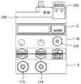
다음으로, 도 5a 는 본 발명의 일 실시형태에 따른 복합형 유체 레벨 측정 장치의 정면도이다. 상술한 바와 같이 제1바디, 제2바디, 제3바디가 차례로 적층되어 본 발명에 따른 복합형 유체 레벨 측정 장치를 구성하며, 제1바디에는 스톱밸브(114), 블로우 밸브(116)가 마련된다. 또한 제2바디에는 제2내부관로(152)를 통해 제3챔버(150)와 연결되는 시그널 단자와 제3내부관로(154)를 통해 제3챔버(150)와 연결되는 지시계단자가 마련되며, 유량을 조절할 수 있는 유량제어밸브(156)도 마련된다. 제3바디에는 PCB 기판을 포함한 신호출력장치(180)가 형성될 수 있으며, 여기에 연결되는 입출력단자(183)도 형성될 수 있다. 상기 신호출력장치(180)는 탱크 내의 유체의 수두압을 측정하여 전기신호로 변환하는 역할을 한다.
Next, FIG. 5A is a front view of the hybrid fluid level measuring device according to one embodiment of the present invention. As described above, the first body, the second body, and the third body are sequentially stacked to form a complex fluid level measuring apparatus according to the present invention. The first body includes a
한편, 도 5b 에 도시된 바와 같이, 본 발명에 따른 복합형 유체 레벨 측정 장치는 압력센서(170)를 더욱 포함할 수 있으며, 압력센서(170)는 제3내부관로(154)에 연결되어 제3챔버(150) 내의 공기압을 센싱하여 신호출력장치(180)로 전달한다. 이 때, 압력센서(170)는 실리콘 소재로 감싸지는 것이 바람직하다.On the other hand, as shown in Figure 5b, the hybrid fluid level measurement apparatus according to the present invention may further include a
다음으로 본 발명에 따른 유체 레벨 측정 및 게이지 세이빙 동작을 설명한다. 공기조절장치부(100)는 공기공급장치로부터 압축공기를 공급받아 안정화된 공기압을 발생시킴으로써 탱크 내의 유체의 레벨을 측정한다. 즉, 공기조절장치부(100)의 공기주입구(112)로는 압축공기가 유입되고, 출구측에서는 제어된 공기가 배출되어 유체가 담긴 탱크로 전달된다. 구체적으로 공기조절장치부(100)의 하부에 위치한 제1챔버(110)에는 공기유입구(112)가 연결되어, 상기 공기유입구(112)를 통해 별도의 공기공급장치로부터 압축공기가 공급되고, 제1챔버(110)에 연결되는 스톱 밸브(114)를 이용하여 공기의 공급 제어할 수 있다.
Next, the fluid level measurement and gauge saving operation according to the present invention will be described. The
한편, 상술한 바와 같이 제1챔버(110)와 제2챔버 사이에는 릴리프 밸브(120)가 마련되어 이들 공간을 구획하는데, 제1챔버(110)에는 공기공급장치로부터 공급된 압축 공기(본 실시예에서는 4.5kg/cm2)가 저장되어 있고, 제2챔버에는 유체의 수두압에 대한 배압을 갖는 공기가 저장되어 있으므로, 제1챔버(110)와 제2챔버의 압력차에 의해 릴리프 밸브(120)가 개폐된다. 즉, 처음에는 개방되어 있는 릴리프 밸브(120)를 통해 제1챔버(110)에서 제2챔버로 압력차에 의해 공기가 이동하다가 제2챔버 내의 공기압에 따라 모듈레이터 다이아프램(140)이 압축되면 릴리프 밸브(120)가 폐쇄되어 제1챔버(110)에서 제2챔버로의 공기의 이동이 중단되고 평형 상태를 이룬다.
Meanwhile, as described above, a
한편, 공기조절장치부(100)의 제3챔버(150)는 제1내부관로(132)를 통해 제2챔버와 연통되며, 제2내부관로(152)를 통해 연료 탱크와 접속되며, 제3내부관로(154)를 통해 지시계와 접속된다. 제3챔버(150)에는 유량조절밸브가 연결되어 있어 이를 이용하여 유량을 조절할 수 있다. 즉, 제3챔버(150)에 모인 공기는 유량조절밸브를 통해 일정량으로 조정되어 제2내부관로(152)를 통해 연료탱크로 유입되고, 제3내부관로(154)를 통해 지시계로도 유입된다.
On the other hand, the
공기조절장치부의 유량을 측정하는 구체적인 동작은 본 출원인의 등록실용신안 제 239839호에 구체적으로 개시되어 있으므로 본 명세서에서는 더 이상의 설명은 생략하도록 한다.
Since the specific operation of measuring the flow rate of the air conditioner unit is specifically disclosed in Korean Utility Model Registration No. 239839, the description thereof will be omitted.
한편, 본 발명에 따른 유체 레벨 측정 장치를 구성하는 게이지 세이버(200)는 평상시에는 탱크 내의 유체의 수두압에 의해 형성된 배압을 지시계와 압력 센서로 전달한다. 만약 탱크 내에 이상 압력이 발생하는 경우에는 제2내부관로(152)를 통해 제3챔버 (150)내에 이상 압력이 감지되고 제3챔버(150)와 제4챔버(160)의 압력차에 의해 게이지 세이버 스풀(240)이 상승하여 게이지 세이버 니플(260)을 폐쇄한다. 이에 따라 게이지 세이버 니플(260)에 연결되어 있는 제3내부관로(154)를 차단하여 지시계 및 압력 센서를 보호할 수 있다.
On the other hand, the
상기와 같은 구성으로 인해, 유체 탱크 내의 이상 압력 발생 등으로 인해 이상 압력 공기가 제2내부관로(152)를 통해 제3챔버(150) 내로 유입되면, 지시계 및 압력 센서로 연결되는 관로를 즉시 차단하여 손상에 취약한 지시계 등의 장치를 보호할 수 있게 되는 것이다.
Due to the above configuration, when abnormal pressure air flows into the
또한 블로잉 작업 시에도 제2내부관로(152)를 통해 제3챔버(150)에 이상 압력이 감지되므로 게이지 세이버(200)가 동작하여 지시계 및 압력 센서를 보호할 수 있게 된다.
In addition, since the abnormal pressure is sensed in the
이상 본 발명의 설명을 위하여 도시된 실시예는 본 발명이 구체화되는 하나의 실시예에 불과하며, 도면에 도시된 바와 같이 본 발명의 요지가 실현되기 위하여 다양한 형태의 조합이 가능함을 알 수 있다.
Embodiments shown for the purpose of the present invention described above are only one embodiment in which the present invention is embodied, and as shown in the drawings, it can be seen that various forms of combinations are possible to realize the gist of the present invention.
따라서 본 발명은 상기한 실시예에 한정되지 않고, 이하의 특허청구범위에서 청구하는 바와 같이 본 발명의 요지를 벗어남이 없이 당해 발명이 속하는 분야에서 통상의 지식을 가진 자라면 누구든지 다양한 변경실시가 가능한 범위까지 본 발명의 기술적 정신이 있다고 할 것이다.
Therefore, the present invention is not limited to the above-described embodiments, and various changes can be made by any person having ordinary skill in the art without departing from the gist of the present invention as claimed in the following claims. It will be said that the technical spirit of this invention is to the extent possible.
100: 공기조절장치부 110: 제1챔버
112: 공기유입구 114: 스톱밸브
116:블로우밸브 120:릴리프밸브
130:제2챔버 132: 제1내부관로
140:모듈레이터 다이아프램 142:모듈레이터 스프링
144:고정홈 150:제3챔버
152:제2내부관로 153:홈
154:제3내부관로 156:유량제어밸브
160:제4챔버 170: 압력센서
180:신호출력장치 183:입출력단자
200:게이지 세이버 210:게이지 세이버 하판
220:게이지 세이버 다이아프램 230:게이지 세이버 상판
240:게이지 세이버 스풀 242:봉상부재
244:원판형 플레이트 246:나사홈
248:고무판 250: 너트
260: 게이지 세이버 니플 270: 게이지 세이버 스프링
100: air conditioning unit 110: the first chamber
112: air inlet 114: stop valve
116: blow valve 120: relief valve
130: second chamber 132: first internal pipeline
140: modulator diaphragm 142: modulator spring
144: fixed groove 150: third chamber
152: Second internal pipe 153: Home
154: third internal pipe 156: flow control valve
160: fourth chamber 170: pressure sensor
180: signal output device 183: I / O terminal
200: gauge saber 210: gauge saber bottom
220: gauge saber diaphragm 230: gauge saber top
240: gauge saber spool 242: rod member
244: disc plate 246: screw groove
248: rubber plate 250: nut
260: gauge saber nipple 270: gauge saber spring
Claims (8)
Translated fromKorean공기 공급 장치로부터 압축 공기를 인가받아 안정된 기체압의 공기를 상기 탱크로 발생시키는 공기조절장치부;
상기 탱크 내의 유체의 수두압에 대한 배압을 표시하는 지시계;
하나 이상의 내부관로를 포함하여 이루어지되, 상기 유체의 수두압에 대한 배압을 지시계로 전달하는 전달부; 및
상기 공기조절장치부의 상부에 마련되어, 이상 압력 발생시 상기 지시계로의 내부관로를 차단하는 게이지 세이버부를 포함하여 이루어지며,
상기 공기조절장치부는 유입된 압축 공기를 저장하는 제1챔버와, 상기 유체의 수두압에 대한 배압을 갖는 공기를 저장하는 제2챔버와, 상기 제1챔버와 상기 제2챔버 사이에 마련되되 상기 제1챔버와 상기 제2챔버의 압력차에 의해 개폐되는 릴리프밸브와, 상기 제2챔버와 제1내부관로를 통해 연결되되, 유량제어밸브에 접속되어 상기 유량제어밸브에 의해 제어된 유량의 공기를 저장하는 제3챔버를 포함하여 이루어지되, 상기 제3챔버는 제2내부관로를 통해 상기 탱크에 접속되는 것을 특징으로 하는 유체 레벨 측정 장치.
A complex fluid level measurement device for measuring the level of fluid in a tank,
An air conditioner unit receiving compressed air from an air supply device to generate air having a stable gas pressure to the tank;
An indicator indicating a back pressure relative to the head pressure of the fluid in the tank;
A transmission unit including one or more inner pipes and transmitting a back pressure to the indicator of the head pressure of the fluid; And
It is provided on the upper part of the air conditioner, and comprises a gauge saver part for blocking the internal passage to the indicator when abnormal pressure is generated,
The air control unit is provided between the first chamber for storing the compressed air introduced, the second chamber for storing the air having a back pressure with respect to the head pressure of the fluid, and is provided between the first chamber and the second chamber A relief valve opened and closed by a pressure difference between the first chamber and the second chamber, and the second chamber and the first internal pipe are connected to each other, and are connected to a flow control valve to control the air of the flow rate controlled by the flow control valve. It comprises a third chamber for storing the fluid level measuring device, characterized in that the third chamber is connected to the tank through a second inner conduit.
상기 게이지 세이버부는 게이지 세이버 하판, 게이지 세이버 다이아프램, 게이지 세이버 상판, 및 하부에 원판형 플레이트가 형성된 게이지 세이버 스풀을 포함하여 이루어지되, 상기 원판형 플레이트는 상기 제3챔버의 내부에 위치하여, 제3챔버 내의 압력변화에 의해 상하로 유동하는 것을 특징으로 하는 유체 레벨 측정 장치.
The method of claim 2,
The gauge saver portion includes a gauge saber bottom plate, a gauge saber diaphragm, a gauge saber top plate, and a gauge saber spool having a disc-shaped plate formed at the bottom thereof, wherein the disc-shaped plate is located inside the third chamber. A fluid level measuring device, characterized in that it flows up and down by the pressure change in the three chambers.
상기 제3챔버는 제3내부관로를 통해 상기 지시계와 접속되며, 상기 제3챔버 상면에는 상기 제3내부관로의 일단 주위로 소정 깊이의 홈이 형성되고, 상기 홈 안에서 게이지 세이버 니플이 상기 제3내부관로의 일단에 결합되어, 상기 게이지 세이버 스풀의 상하 유동에 의해 상기 게이지 세이버 니플이 개폐되는 것을 특징으로 하는 유체 레벨 측정 장치.
The method of claim 3, wherein
The third chamber is connected to the indicator through a third inner conduit, and a groove having a predetermined depth is formed on one side of the third inner conduit on an upper surface of the third chamber, and a gauge saver nipple is formed in the groove. Is coupled to one end of the inner passage, the fluid level measuring device characterized in that the gauge saber nipple is opened and closed by the up and down flow of the gauge saber spool.
상기 유체 레벨 측정 장치는, 상기 제1챔버와 상기 제2내부관로에 연통되는 블로우 밸브를 더 포함하고, 상기 블로우 밸브를 통해 공기를 주입함으로써 상기 유체 레벨 측정 장치 내의 이물질을 제거할 수 있는 것을 특징으로 하는 유체 레벨 측정 장치.
The method of claim 4, wherein
The fluid level measuring device may further include a blow valve in communication with the first chamber and the second inner conduit, and may remove foreign substances in the fluid level measuring device by injecting air through the blow valve. Fluid level measuring device.
상기 블로우 밸브를 통해 공기를 주입할 때, 상기 게이지 세이버 스풀이 상기 게이지 세이버 니플을 폐쇄하는 것을 특징으로 하는 유체 레벨 측정 장치.
The method of claim 5, wherein
And the gauge saver spool closes the gauge saver nipple when injecting air through the blow valve.
상기 유체 레벨 측정 장치는 상기 제3내부관로에 연결되어 상기 제3챔버 내의 공기압을 센싱하는 압력 센서를 더 포함하며, 상기 압력 센서는 실리콘 튜브 패킹을 사용하여 내부에 결합되는 것을 특징으로 하는 유체 레벨 측정 장치.
The method according to any one of claims 4 to 6,
The fluid level measuring device further includes a pressure sensor connected to the third internal conduit to sense air pressure in the third chamber, wherein the pressure sensor is coupled to the inside using a silicon tube packing. Measuring device.
상기 유체 레벨 측정 장치는, 상기 게이지 세이버부에 접속되어, 상기 유체의 수두압을 측정하여 전기신호 또는 전자신호로 변환하는 신호출력장치를 더 포함하는 것을 특징으로 하는 유체 레벨 측정 장치.The method according to any one of claims 2 to 6,
The fluid level measuring device further includes a signal output device connected to the gauge saver unit and measuring the head pressure of the fluid and converting the fluid level into an electrical signal or an electronic signal.
Priority Applications (1)
| Application Number | Priority Date | Filing Date | Title |
|---|---|---|---|
| KR1020100067496AKR101033132B1 (en) | 2010-07-13 | 2010-07-13 | Hybrid Fluid Level Measuring Device |
Applications Claiming Priority (1)
| Application Number | Priority Date | Filing Date | Title |
|---|---|---|---|
| KR1020100067496AKR101033132B1 (en) | 2010-07-13 | 2010-07-13 | Hybrid Fluid Level Measuring Device |
Publications (1)
| Publication Number | Publication Date |
|---|---|
| KR101033132B1true KR101033132B1 (en) | 2011-05-11 |
Family
ID=44365672
Family Applications (1)
| Application Number | Title | Priority Date | Filing Date |
|---|---|---|---|
| KR1020100067496AActiveKR101033132B1 (en) | 2010-07-13 | 2010-07-13 | Hybrid Fluid Level Measuring Device |
Country Status (1)
| Country | Link |
|---|---|
| KR (1) | KR101033132B1 (en) |
Cited By (1)
| Publication number | Priority date | Publication date | Assignee | Title |
|---|---|---|---|---|
| KR102243337B1 (en) | 2020-08-26 | 2021-04-22 | 주식회사 티엔에스 | Level gauge through controlling open area of air gate hole |
Citations (3)
| Publication number | Priority date | Publication date | Assignee | Title |
|---|---|---|---|---|
| JPS6156915A (en) | 1984-08-27 | 1986-03-22 | Toshiba Corp | Purge type liquid level gauge |
| US20040147893A1 (en)* | 2001-05-22 | 2004-07-29 | Uni-Charm Corporation | Interlabial pad |
| KR20050071781A (en)* | 2004-01-02 | 2005-07-08 | 범아정밀(주) | Liquid level measuring device |
- 2010
- 2010-07-13KRKR1020100067496Apatent/KR101033132B1/enactiveActive
Patent Citations (3)
| Publication number | Priority date | Publication date | Assignee | Title |
|---|---|---|---|---|
| JPS6156915A (en) | 1984-08-27 | 1986-03-22 | Toshiba Corp | Purge type liquid level gauge |
| US20040147893A1 (en)* | 2001-05-22 | 2004-07-29 | Uni-Charm Corporation | Interlabial pad |
| KR20050071781A (en)* | 2004-01-02 | 2005-07-08 | 범아정밀(주) | Liquid level measuring device |
Cited By (1)
| Publication number | Priority date | Publication date | Assignee | Title |
|---|---|---|---|---|
| KR102243337B1 (en) | 2020-08-26 | 2021-04-22 | 주식회사 티엔에스 | Level gauge through controlling open area of air gate hole |
Similar Documents
| Publication | Publication Date | Title |
|---|---|---|
| AU611569B2 (en) | Leak detector | |
| KR101425007B1 (en) | Mass flow verifiers capable of providing different volumes, and related methods | |
| CN109724667B (en) | Method and system for detecting volume percentage of liquid in container and dispenser with system | |
| CN104089680B (en) | The measuring method and device of liquid level height | |
| CN204007743U (en) | For providing and delivering and measuring system and the measurement chamber of cryogenic liquid | |
| US20060204404A1 (en) | Continuous flow chemical metering apparatus | |
| JP2018506703A (en) | Method for determining the amount of gas and apparatus for carrying out this method | |
| CN107782420A (en) | A kind of automobile oil truck capacity Quick calibration device and method | |
| KR101033132B1 (en) | Hybrid Fluid Level Measuring Device | |
| CN109632036B (en) | A gas volume measurement displacement device | |
| US5901603A (en) | Liquid level monitor | |
| KR101329253B1 (en) | Test apparatus for pressure senser | |
| ATE439425T1 (en) | AUTOMATIC FERMENTATION SYSTEM AND FERMENTATION CONTROL | |
| KR101639033B1 (en) | Temperature and Volume Measuring System of Fuel Tank at Vehicle by using Gas Pump | |
| JPH0246090B2 (en) | ||
| CN110726557B (en) | 1N single-component thruster test system and method | |
| US9400055B2 (en) | Bladder accumulator volume indicating device | |
| CN201307047Y (en) | Gas pressure detecting device, differential pressure type liquid level measuring device and tank type transporting container | |
| JP4171664B2 (en) | Liquid volume measuring device | |
| CN201897489U (en) | Mass flowmeter for integrated V-shaped cone | |
| JP2010255530A (en) | Liquid flow measuring device | |
| CN211783706U (en) | Metering device for fluid supply system and fluid supply system | |
| CN203727990U (en) | Measuring apparatus for internal liquid levels of tanks | |
| CN221348045U (en) | On-spot adjustable micropressure bleeder | |
| KR101663541B1 (en) | Temperature and Revised Volume Measuring System of Fuel Tank at Vehicle |
Legal Events
| Date | Code | Title | Description |
|---|---|---|---|
| A201 | Request for examination | ||
| PA0109 | Patent application | Patent event code:PA01091R01D Comment text:Patent Application Patent event date:20100713 | |
| PA0201 | Request for examination | ||
| A302 | Request for accelerated examination | ||
| PA0302 | Request for accelerated examination | Patent event date:20100908 Patent event code:PA03022R01D Comment text:Request for Accelerated Examination Patent event date:20100713 Patent event code:PA03021R01I Comment text:Patent Application | |
| E902 | Notification of reason for refusal | ||
| PE0902 | Notice of grounds for rejection | Comment text:Notification of reason for refusal Patent event date:20101028 Patent event code:PE09021S01D | |
| E701 | Decision to grant or registration of patent right | ||
| PE0701 | Decision of registration | Patent event code:PE07011S01D Comment text:Decision to Grant Registration Patent event date:20110126 | |
| GRNT | Written decision to grant | ||
| PR0701 | Registration of establishment | Comment text:Registration of Establishment Patent event date:20110428 Patent event code:PR07011E01D | |
| PR1002 | Payment of registration fee | Payment date:20110428 End annual number:3 Start annual number:1 | |
| PG1601 | Publication of registration | ||
| FPAY | Annual fee payment | Payment date:20140425 Year of fee payment:4 | |
| PR1001 | Payment of annual fee | Payment date:20140425 Start annual number:4 End annual number:4 | |
| FPAY | Annual fee payment | Payment date:20150210 Year of fee payment:5 | |
| PR1001 | Payment of annual fee | Payment date:20150210 Start annual number:5 End annual number:5 | |
| FPAY | Annual fee payment | Payment date:20160422 Year of fee payment:6 | |
| PR1001 | Payment of annual fee | Payment date:20160422 Start annual number:6 End annual number:6 | |
| FPAY | Annual fee payment | Payment date:20170404 Year of fee payment:7 | |
| PR1001 | Payment of annual fee | Payment date:20170404 Start annual number:7 End annual number:7 | |
| FPAY | Annual fee payment | Payment date:20180403 Year of fee payment:8 | |
| PR1001 | Payment of annual fee | Payment date:20180403 Start annual number:8 End annual number:8 | |
| FPAY | Annual fee payment | Payment date:20190404 Year of fee payment:9 | |
| PR1001 | Payment of annual fee | Payment date:20190404 Start annual number:9 End annual number:9 | |
| PR1001 | Payment of annual fee | Payment date:20200407 Start annual number:10 End annual number:10 | |
| PR1001 | Payment of annual fee | Payment date:20220411 Start annual number:12 End annual number:12 | |
| PR1001 | Payment of annual fee | Payment date:20230406 Start annual number:13 End annual number:13 | |
| PR1001 | Payment of annual fee | Payment date:20240327 Start annual number:14 End annual number:14 | |
| PR1001 | Payment of annual fee | Payment date:20250317 Start annual number:15 End annual number:15 |