KR101030773B1 - Solar Tracker Using Satellite Navigation System - Google Patents
Solar Tracker Using Satellite Navigation SystemDownload PDFInfo
- Publication number
- KR101030773B1 KR101030773B1KR1020090134730AKR20090134730AKR101030773B1KR 101030773 B1KR101030773 B1KR 101030773B1KR 1020090134730 AKR1020090134730 AKR 1020090134730AKR 20090134730 AKR20090134730 AKR 20090134730AKR 101030773 B1KR101030773 B1KR 101030773B1
- Authority
- KR
- South Korea
- Prior art keywords
- solar
- collecting plate
- step motor
- light collecting
- shaft
- Prior art date
- Legal status (The legal status is an assumption and is not a legal conclusion. Google has not performed a legal analysis and makes no representation as to the accuracy of the status listed.)
- Expired - Fee Related
Links
Images


Classifications
- F—MECHANICAL ENGINEERING; LIGHTING; HEATING; WEAPONS; BLASTING
- F24—HEATING; RANGES; VENTILATING
- F24S—SOLAR HEAT COLLECTORS; SOLAR HEAT SYSTEMS
- F24S50/00—Arrangements for controlling solar heat collectors
- F24S50/20—Arrangements for controlling solar heat collectors for tracking
- H—ELECTRICITY
- H02—GENERATION; CONVERSION OR DISTRIBUTION OF ELECTRIC POWER
- H02S—GENERATION OF ELECTRIC POWER BY CONVERSION OF INFRARED RADIATION, VISIBLE LIGHT OR ULTRAVIOLET LIGHT, e.g. USING PHOTOVOLTAIC [PV] MODULES
- H02S20/00—Supporting structures for PV modules
- H02S20/30—Supporting structures being movable or adjustable, e.g. for angle adjustment
- H02S20/32—Supporting structures being movable or adjustable, e.g. for angle adjustment specially adapted for solar tracking
- F—MECHANICAL ENGINEERING; LIGHTING; HEATING; WEAPONS; BLASTING
- F24—HEATING; RANGES; VENTILATING
- F24S—SOLAR HEAT COLLECTORS; SOLAR HEAT SYSTEMS
- F24S30/00—Arrangements for moving or orienting solar heat collector modules
- F24S30/40—Arrangements for moving or orienting solar heat collector modules for rotary movement
- F24S30/45—Arrangements for moving or orienting solar heat collector modules for rotary movement with two rotation axes
- F24S30/455—Horizontal primary axis
- Y—GENERAL TAGGING OF NEW TECHNOLOGICAL DEVELOPMENTS; GENERAL TAGGING OF CROSS-SECTIONAL TECHNOLOGIES SPANNING OVER SEVERAL SECTIONS OF THE IPC; TECHNICAL SUBJECTS COVERED BY FORMER USPC CROSS-REFERENCE ART COLLECTIONS [XRACs] AND DIGESTS
- Y02—TECHNOLOGIES OR APPLICATIONS FOR MITIGATION OR ADAPTATION AGAINST CLIMATE CHANGE
- Y02E—REDUCTION OF GREENHOUSE GAS [GHG] EMISSIONS, RELATED TO ENERGY GENERATION, TRANSMISSION OR DISTRIBUTION
- Y02E10/00—Energy generation through renewable energy sources
- Y02E10/40—Solar thermal energy, e.g. solar towers
- Y02E10/47—Mountings or tracking
- Y—GENERAL TAGGING OF NEW TECHNOLOGICAL DEVELOPMENTS; GENERAL TAGGING OF CROSS-SECTIONAL TECHNOLOGIES SPANNING OVER SEVERAL SECTIONS OF THE IPC; TECHNICAL SUBJECTS COVERED BY FORMER USPC CROSS-REFERENCE ART COLLECTIONS [XRACs] AND DIGESTS
- Y02—TECHNOLOGIES OR APPLICATIONS FOR MITIGATION OR ADAPTATION AGAINST CLIMATE CHANGE
- Y02E—REDUCTION OF GREENHOUSE GAS [GHG] EMISSIONS, RELATED TO ENERGY GENERATION, TRANSMISSION OR DISTRIBUTION
- Y02E10/00—Energy generation through renewable energy sources
- Y02E10/50—Photovoltaic [PV] energy
Landscapes
- Engineering & Computer Science (AREA)
- Life Sciences & Earth Sciences (AREA)
- Sustainable Development (AREA)
- Physics & Mathematics (AREA)
- Sustainable Energy (AREA)
- Thermal Sciences (AREA)
- Chemical & Material Sciences (AREA)
- Combustion & Propulsion (AREA)
- Mechanical Engineering (AREA)
- General Engineering & Computer Science (AREA)
- Photovoltaic Devices (AREA)
Abstract
Translated fromKoreanDescription
Translated fromKorean본 발명은 태양광을 전기에너지로 변환하는 태양광발전기에서 태양광의 입사위치에 따라 가변하면서 태양광이 최적으로 입사될 수 있도록 하는 태양광집광기의 각도를 자동으로 조절하는 태양광 트랙커에 관한 것으로서, 더욱 상세하게는 위성항법장치(GPS: Global Positioning System)를 이용하여 태양광이 최적으로 입사될 수 있도록 집광기의 각도를 조절함과 아울러 자체 전원에 의하여 구동되어 발전된 전력을 송출할 수 있도록 하는 위성항법장치를 이용한 태양광 트랙커에 관한 것이다.The present invention relates to a solar tracker for automatically adjusting the angle of the photoconcentrator so that the solar light can be optimally input while varying according to the position of incidence of sunlight in the photovoltaic generator for converting sunlight into electrical energy, More specifically, the satellite navigation system uses the Global Positioning System (GPS) to adjust the angle of the collector so that sunlight can be optimally incident and to transmit the generated power driven by its own power source. A solar tracker using the device.
일반적으로 태양광 발전기는 태양전지와 축전지 그리고 전력변환장치로 구성되어 있으며, 태양전지가 다수 설치되어 있는 태양광집광판으로 태양광을 집광하여 광에너지를 전기에너지로 변환시키는 발전설비이다. 이러한 태양광 발전기는 태양전지의 설치수량에 따라 발전용량이 달라지므로 필요한 장소에 필요한 만큼만 발전할 수 있어서 대규모 발전뿐만 아니라 소규모 발전이 가능하여 가정용, 산업용으로 널리 이용되고 있는 추세이다.In general, a solar generator is composed of a solar cell, a storage battery, and a power converter, and is a solar light collecting plate installed with a large number of solar cells to collect solar light and convert light energy into electric energy. Since the power generation capacity varies depending on the quantity of solar cells installed, the solar power generators can be generated only as needed, so that large-scale power generation as well as small-scale power generation are widely used for home and industrial use.
이러한 태양광 발전기는 태양광집광판의 설치방식에 따라 고정형과 태양추적 형으로 구분할 수 있다.Such solar generators can be classified into fixed type and solar tracking type according to the installation method of the solar light collecting plate.
고정형 태양광 발전기는 일조량을 가장 많이 받을 수 있는 각도로 태양광집판이 고정된 형태인데, 이는 구조가 단순하여 설치가 용이하고, 내구성이 높아 유지보수가 간편하다는 장점이 있지만, 태양광의 입사각에 따라 발전량의 편차가 심하여 평균 발전효율이 좋지 않다는 단점이 있다.The fixed type solar generator is a type in which a solar collector is fixed at an angle capable of receiving the most amount of sunshine, which is simple in structure and easy to install, and has high durability and easy maintenance, but according to the incident angle of solar power There is a disadvantage in that the average power generation efficiency is not good because of a large deviation.
한편, 태양추적형 태양광 발전기는 일출에서 일몰까지 동에서 서로 이동하는 태양의 운동을 추적하도록 태양광집광판을 회전시키는 1축 회전식과, 태양의 남중고도 변화까지 추적하도록 태양전지 모듈을 회전시키는 2축 회전식으로 구분할 수 있는데, 1축 회전식은 상대적으로 구동장치의 구조가 간단하지만 2축 회전식에 비해 발전효율이 떨어지는 문제점이 있고, 이에 비해 2축 회전식은 태양광의 입사방향이 태양전지 모듈과 항상 수직을 이루어 발전효율을 극대화할 수 있는 이점이 있다.On the other hand, the solar tracking photovoltaic generator is a one-axis rotation to rotate the solar panel to track the movement of the sun moving from east to west from sunrise to sunset, and to rotate the solar cell module to track the change in the mid-high altitude of the sun It can be divided into two-axis rotary type, but the one-axis rotary type has a relatively simple structure of the driving device, but the power generation efficiency is lower than that of the two-axis rotary type. There is an advantage to maximize the power generation efficiency in the vertical.
이러한 태양추적형 태양광 발전기들은 크게 보아 프로그램에 의하여 계산된 좌표에 따라 구동모터가 작동되어 태양을 추적하는 좌표 계산방식과, 수시로 광센서에 의하여 검출되는 신호출력에 따라 구동모터를 제어하여 태양을 추적하는 광센서방식의 두 가지로 분류할 수 있다.These solar tracking photovoltaic generators largely control the sun by controlling the driving motor according to the coordinate calculation method of tracking the sun by operating the driving motor according to the coordinates calculated by the program, and the signal output detected by the optical sensor from time to time. It can be classified into two types of tracking optical sensors.
그러나, 전술한 좌표 계산방식은 일기상태에 구애받지 않고 태양을 추종할 수 있다는 장점이 있는 반면에 오차의 누적으로 주기적으로 교정작업을 하여야 하므로 유지, 보수의 번거로움이 있고, 광센서 방식은 그 구조가 비교적 간결하다는 장점은 있으나 날씨가 흐린 경우에는 태양의 추적이 불가능하고 이러한 상태로 시 간이 경과되어 태양의 위치가 상당히 변화된 경우에는 태양이 추적장치의 추적가능범위를 벗어나게 되어 추적 자체가 불가능하게 될 수도 있어서 작동의 연속성이 유지되기 어렵다는 등의 문제점이 있다.However, the above-described coordinate calculation method has the advantage of being able to follow the sun regardless of the weather condition, but it is cumbersome to maintain and repair since the calibration work must be periodically performed due to the accumulation of errors. The advantage is that the structure is relatively simple. However, if the weather is cloudy, the sun cannot be traced. If the time has elapsed and the position of the sun has changed considerably, the sun will be out of the traceable range of the tracking device. There may be problems such as difficulty in maintaining continuity of operation.
한편, 태양광발전기는 제어방법에 따라 계통연계형과 독립형으로 나뉘는데, 계통연계형은 태양광 발전과 상용전원을 연계하여 태양광 발전이 부족할 경우에는 상용전원을 사용하는 시스템이고, 독립형은 외딴 섬이나 산악지역과 같이 상용전원이 들어오지 않는 지역에서 태양광발전된 전력을 자체 축전지에 저장하여 사용하는 시스템으로써, 일반적으로 상용전원의 전력선이 연결되지 않는 곳에서는 축전지를 구비할 필요가 있다.On the other hand, photovoltaic generators are divided into grid-connected type and independent type according to the control method. Grid-connected type is a system that uses commercial power when solar power is insufficient by linking solar power and commercial power. As a system for storing and using photovoltaic power in its own battery in an area where commercial power does not come in, such as a mountainous area, it is generally necessary to provide a battery in a place where the power line of the commercial power source is not connected.
본 발명은 상기한 사정을 감안하여 발명한 것으로, 상용전원이 공급되지 않는 지역에서 사용가능하도록 하고, 위성항법장치를 이용하여 태양의 위치를 판단하고 G센서(중력센서)를 이용하여 태양광집광판의 각도를 판단한 후 스텝모터의 구동에 의해 태양광집광판을 태양광이 수직으로 입사되는 방향으로 자동조절할 수 있도록 된 위성항법장치를 이용한 태양광 트랙커를 제공하고자 함에 발명의 목적이 있다.The present invention has been invented in view of the above-described circumstances, and can be used in an area where commercial power is not supplied, and determines the position of the sun by using a satellite navigation device and uses a G-sensor (gravity sensor) An object of the present invention is to provide a solar tracker using a satellite navigation apparatus that is capable of automatically adjusting the solar light collecting plate in the direction in which sunlight is incident by the driving of the step motor after determining the angle of.
또한, 태양광집광판의 각도를 조절하기 위한 회전축을 수평축으로 설치하여 대용량 소형화가 가능하게 하며, 상기 회전축을 회전시키는 스텝모터는 착탈식으로 구성하여 태양광집광판의 무게에 따라 스텝모터를 용이하게 부하에 맞는 것으로 교체할 수 있도록 된 위성항법장치를 이용한 태양광 트랙커를 제공하고자 함에 발명의 목적이 있다.In addition, by installing a rotating shaft for adjusting the angle of the solar light panel in a horizontal axis, it is possible to miniaturize a large capacity, and the step motor for rotating the rotating shaft is configured to be removable to easily load the step motor according to the weight of the solar light panel. An object of the present invention is to provide a solar tracker using a satellite navigation system that can be replaced with a suitable one.
상기한 목적을 달성하기 위한 본 발명은, 광에너지를 전기에너지로 변환하는 태양전지군이 설치되어 있는 태양광집광판; 상기 태양광집광판을 스텝모터의 구동으로 수평방향으로 회전시키는 수평구동부와 상기 태양광집광판을 스텝모터의 구동으로 수직방향으로 회전시키는 수직구동부가 일체로 이루어진 집광판 방향조절기구; GPS위성으로부터 위도, 경도 및 시간정보를 수신하는 GPS수신부; 상기 태양광집광판의 경사도를 감지하는 G센서; 상기 GPS수신부와 G센서의 수신정보로부터 계 절별, 날짜별로 상기 수평구동부와 수직구동부를 제어하여 태양광집광판을 태양광이 수직으로 입사하는 방향으로 제어하는 제어부; 상기 태양전지군에서 발전된 전기를 축전하는 축전지를 포함하여 이루어져 있다.The present invention for achieving the above object, the solar light collecting plate is provided with a solar cell group for converting light energy into electrical energy; A light collecting plate direction control mechanism including a horizontal driving unit for rotating the solar light collecting plate in a horizontal direction by driving of the step motor and a vertical driving unit for rotating the solar light collecting plate in a vertical direction by driving of the step motor; A GPS receiver for receiving latitude, longitude, and time information from a GPS satellite; A G-sensor for detecting the inclination of the solar light collecting plate; A control unit controlling the solar light collecting plate in a direction in which sunlight is incident vertically by controlling the horizontal driving unit and the vertical driving unit by season and date from the reception information of the GPS receiver and the G sensor; It comprises a storage battery for storing electricity generated in the solar cell group.
상기 집광판 방향조절기구는 수평회전축과 수직회전축이 하단과 상단에서 서로 직교하는 방향으로 평행하면서 선회가능하게 축결합되어 있는 축고정구, 상기 수직회전축의 양단에 축결합되며 중앙에 태양광집광판고정부가 형성된 상부프레임, 상기 수평회전축의 양단에 축결합되며 중앙에 설치대고정부가 형성된 하부프레임, 상기 수평회전축의 일단에 수평회전축을 수평방향으로 회전시키도록 기어박스를 매개로 결합되는 수평회동 스텝모터, 상기 수직회전축의 일단에 수직회전축을 수직방향으로 회전시키도록 기어박스를 매개로 결합되는 수직회동 스텝모터를 포함하여 이루어져 있다.The light collecting plate direction adjusting mechanism includes a shaft fixture having a horizontal rotating shaft and a vertical rotating shaft pivotally coupled in a direction perpendicular to each other at the bottom and the top thereof, and being coupled to both ends of the vertical rotating shaft and having a solar light collecting plate fixing part at the center thereof. An upper frame, a lower frame having shafts coupled to both ends of the horizontal rotating shaft, and having a fixing unit installed at the center thereof, a horizontal rotating step motor coupled to a gear box to rotate the horizontal rotating shaft horizontally at one end of the horizontal rotating shaft; One end of the vertical axis of rotation comprises a vertical rotation step motor coupled via a gearbox to rotate the vertical axis of rotation in the vertical direction.
상기에 있어서, 상기 수직회전축과 수평회전축에서 스텝모터가 부착되는 끝단의 반대쪽 끝단은 브레이크부착 축베어링을 매개로 각각의 프레임에 고정되는 것을 특징으로 한다.In the above, the opposite end of the end to which the step motor is attached in the vertical rotation axis and the horizontal rotation axis is fixed to each frame via the brake bearing shaft bearing.
상기에 있어서, 상기 수평회동 스텝모터와 수직회동 스텝모터의 기어박스는 각각 스텝모터의 회전축에 결합되는 워엄이 형성된 워엄축과, 상기 워엄에 맞물리면서 각각의 수평회전축과 수직회전축에 고정되는 워엄기어로 이루어진 것을 특징으로 한다.In the above, the gearbox of the horizontal rotation step motor and the vertical rotation step motor is a worm shaft formed with a worm coupled to the rotation axis of the step motor, respectively, and the worm gear is fixed to each of the horizontal rotation axis and the vertical rotation shaft while engaging the worm Characterized in that made.
상기에 있어서, 상기 수평회동 스텝모터와 수직회동 스텝모터의 회전축에는 축심을 관통하는 체결핀이 결합되고, 모터회전축에 결합되는 워엄축에는 상기 체결 핀이 끼워지는 체결홈이 형성되어 상기 체결홈과 체결핀의 결합에 의해 모터회전축과 워엄축이 착탈가능하게 결합되는 한편, 스텝모터의 몸체는 기어박스에 볼트체결되어 스텝모터가 기어박스에 착탈가능하게 고정된 것을 특징으로 한다.In the above, the rotating shaft of the horizontal rotating step motor and the vertical rotating step motor is coupled to the fastening pin penetrating the shaft core, the worm shaft coupled to the motor shaft is formed with a fastening groove for fitting the fastening pin is formed with the fastening groove and While the motor rotation shaft and the worm shaft are detachably coupled by the coupling of the fastening pin, the body of the step motor is bolted to the gear box, so that the step motor is detachably fixed to the gear box.
상기에 있어서, 상기 태양광집광판의 방향제어에 필요한 전원은 외부동력없이 자체 축전지에서 공급되는 독립형인 것을 특징으로 한다.In the above, the power required for directional control of the solar light collecting plate is characterized in that the independent type supplied from its own battery without external power.
상기에 있어서, 상기 제어부는 일몰시부터 일출시까지 태양광집광판이 수평상태를 유지하도록 제어하는 것을 특징으로 한다.In the above, the control unit is characterized in that the solar panel is controlled to maintain a horizontal state from sunset to sunrise.
상기한 바와 같은 본 발명에 따른 위성항법장치를 이용한 태양광 트랙커는 계절 및 날짜에 따라 태양광집광판의 방향을 조절하여 태양광이 태양광집광판에 수직으로 입사되도록 함으로써 최적의 발전효율을 도모할 수 있고, 수직 및 수평 회전축을 수평축구조를 이용함으로써 대용량 소형화가 가능한 방향조절기구를 구현할 수 있으며, 상용전원에 연계하지 않고 독립적으로 생성되는 전원을 이용할 수 있도록 함으로써 상용전원이 공급되지 않는 산간벽지, 도서지방 등 취약지역에서 편리하게 사용할 수 있는 장점이 있다.The solar tracker using the satellite navigation apparatus according to the present invention as described above can achieve the optimal power generation efficiency by adjusting the direction of the solar panel according to the season and date so that the sunlight is incident perpendicularly to the solar panel. The vertical and horizontal rotating shafts can be used to implement a direction control mechanism that can be miniaturized in large capacity, and can be used independently of commercial power sources. There is an advantage that can be conveniently used in vulnerable areas such as fat.
이하 본 발명의 바람직한 일실시예에 대한 구성 및 작용을 예시도면에 의거하여 상세히 설명한다.Hereinafter, the configuration and operation of the preferred embodiment of the present invention will be described in detail with reference to the accompanying drawings.
도 1은 본 발명의 사용상태도를 나타낸 것으로, 특히 태양광집광판(1)의 방향조절기구의 설치상태를 설명하기 위해 태양광집광판(1)을 후면측에서 본 사시도 를 나타낸다.1 is a view showing a state of use of the present invention, in particular, showing a perspective view of the solar
도 1에 도시된 바와 같이, 태양광발전설비는 태양광집광판(1)과 설치대(2) 및 집광판 방향조절기구(3)로 이루어져 있다.As shown in FIG. 1, the photovoltaic power generation facility includes a solar
태양광집광판(1)은 태양으로부터 입사되는 광에너지를 전기에너지로 변환하는 태양전지가 전면에 다수 설치되어 있으며, 후면의 프레임이 집광판 방향조절기구(2)를 통해 설치대(3)에 고정되어 있다.In the solar
집광판 방향조절기구(2)는 일측에 상기 태양광집광판(1)이 취부되고 다른 일측이 설치대(3)에 고정되어, 태양광집광판(1)을 수직방향과 수평방향으로 독립적으로 제어하여 회동시킴으로써 태양빛이 태양광집광판(1)에 수직으로 입사될 수 있도록 한다.The light collecting plate
상기 설치대(3)는 상기 집광판 방향조절기구(2)의 다른 일측이 고정되어 상기 태양광집광판(1)을 지지한다. 아울러 도면에는 도시되어 있지 않으나 설치대(3)의 일측에는 태양광집광판(1)에서 발전할 전기를 사용할 부하가 취부될 수 있다.The mounting table 3 is fixed to the other side of the light collecting plate
도 2는 본 발명에 따른 집광판 방향조절기구의 사시도, 도 3은 도 2에 도시된 집광판 방향조절기구의 요부 분해사시도를 나타내는 것으로, 이하에서는 도 2 및 도 3에 의거 집광판 방향조절기구의 구조에 대해 설명한다.Figure 2 is a perspective view of the light collecting plate direction control mechanism according to the present invention, Figure 3 shows an exploded perspective view of the main portion of the light collecting plate direction control mechanism shown in Figure 2, below in the structure of the light collecting plate direction control mechanism according to FIG. Explain.
집광판 방향조절기구(2)는 축고정구(10)의 상부와 하부에 상부프레임(20)과 하부프레임(30)이 각각의 수평회전축(21)과 수직회전축(31)에 의하여 선회가능하게 축결합되어 있다.The light collecting plate
상기 수평회전축(21)과 수직회전축(31)은 축고정구(10)의 하단과 상단에서 서로 직교하는 방향으로 평행하면서 선회가능하게 축결합되어 있다. 이와 같은 구조는 수평회전축(21)과 수직회전축(31)이 수평축으로 고정됨으로서 소형으로 이루어지면서도 대용량의 태양광집광판(1)을 지지할 수 있다.The horizontal rotating
이러한 수평회전축(21)의 일단은 베어링(22)을 매개로 하부프레임(20)의 축홈(23)에 결합됨과 아울러 그 끝단에 기어박스(24)를 매개로 수평회동 스텝모터(25)가 결합되어 있는 한편, 수평회전축(21)의 다른 일단에는 브레이크 베어링(26)을 매개로 하부프레임(20)의 축홈(27)에 결합된다.One end of the horizontal rotating
이와 마찬가지로, 수직회전축(31)의 일단은 베어링(32)을 매개로 상부프레임(30)의 축홈(33)에 결합됨과 아울러 그 끝단에 기어박스(34)를 매개로 수직회동 스텝모터(34; 도시되지 않음)가 결합되어 있는 한편, 수직회전축(31)의 다른 일단에는 브레이크 베어링(36)을 매개로 상부프레임(30)의 축홈(37)에 결합된다.Similarly, one end of the
상기 브레이크 베어링(26,36)은 이에 축결합되는 수평회전축(21)과 수직회전축(31)을 전기적 신호에 따라 제동 또는 회동가능하게 작동가능한 브레이크 기능을 구비하고 있는 것이다. 이는 태양광집광판(1)을 고정하고 있을 때 수평회전축(21)과 수직회전축(31)에 제동력을 부가하여, 바람에 의한 태양광집광판(1)의 흔들림이 수평회전축(21) 또는 수직회전축(31)을 통해 기어박스(24)(34) 및 스텝모터(25)(36)에 전달되어 손상되는 것을 방지하기 위한 것이다.The
하부프레임(20)은 축홈(23)(27)이 형성되어 있는 지지대가 설치대고정부(28)의 양편에 설치된 구조로써, 설치대고정부(28)에는 집광판 방향조절기구(2)를 설치 대(3)에 고정하기 위한 체결홈(29)이 다수 형성되어 볼트 등의 체결부재를 이용하여 설치대(3)에 결합된다.The
상부프레임(20)은 축홈(33)(37)이 형성되어 있는 지지대가 태양광집광판고정부(38)의 양편에 설치된 구조로써, 태양광집광판고정부(38)에는 집광판 방향조절기구(2)에 태양광집광판(1)을 고정하기 위한 체결홈(39)이 다수 형성되어 볼트 등의 체결부재를 이용하여 태양광집광판(1)이 결합된다.The
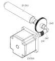
도 4는 본 발명에 따른 스텝모터의 동력전달구조를 나타낸다.4 shows a power transmission structure of a step motor according to the present invention.
수평회동 스텝모터(25)와 수직회동 스텝모터(35)의 동력전달구조는 동일하게 구성된 것이므로 이하에서는 중복설명을 피하기 위하여 수평회동 스텝모터(25)의 동력전달구조에 대하여 설명한다. 그러나 수직회동 스텝모터(35)의 동력전달구조 에 대하여도 동일 사상으로 이해되어야 한다.Since the power transmission structures of the horizontal
수평회동 스텝모터(25)의 회전축(251)에는 워엄(241)이 형성된 워엄축(242)이 고정되고, 상기 워엄(241)과 맞물려있는 워엄기어(243)는 수평회전축(21)에 고정되어있다. 상기 워엄(241) 및 워엄기어(243)는 수평회동 스텝모터(25)의 회전속도를 감속하여 수평회전축(21)에 전달함과 아울러 태양광집광판(1)이 바람에 흔들림에 의해 발생하는 역동력이 수평회동 스텝모터(25)에 전달되는 힘을 최소화시켜 수평회동 스텝모터(25)의 손상을 방지하도록 한다. 이와 같은 동작은 앞서 설명한 브레이크 베어링(26,36)의 작용과 함께 이루어져 수평회동 스텝모터(25)의 손상을 최대한 방지하는 작용을 한다.The
도 5는 본 발명에 따른 스텝모터의 동력축 연결구조를 나타낸다.5 shows a power shaft connection structure of the step motor according to the present invention.
수평회동 스텝모터(25)의 회전축(251)에는 회전축(251)을 관통하는 체결핀(252)이 결합되어 있다. 그리고 회전축(251)과 결합되는 워엄축(242)에는 상기 체결핀(252)이 삽입되는 체결홈(244)이 형성되어 있다. 따라서 상기 체결핀(252)과 체결홈(244)이 맞물려서 수평회동 스텝모터(25)의 동력이 워엄축(242)으로 전달된다. 아울러, 수평회동 스텝모터(25)의 몸체에는 워엄축(242)을 수용하고 있는 기어박스(24)의 몸체에 볼트 등의 체결부재를 사용하여 체결할 수 있는 체결홈(253)이 형성되어 있다.A
따라서 수평회동 스텝모터(25)는 체결홈(253)을 통해 기어박스(24)의 몸체에 착탈가능하게 고정되는바, 이때 수평회동 스텝모터(25)의 회전축(251)과 기어박스(24)의 워엄축(242)은 체결핀(252)과 체결홈(244)에 의해 축결합 또는 축분리됨으로써, 수평회동 스텝모터(25)는 용이하게 기어박스(24)로부터 착탈가능하게 되고, 이는 필요에 따라 수평회동 스텝모터(25)를 적정 용량의 것으로의 대체를 가능하게 한다.Therefore, the horizontal
도 6은 본 발명에 따른 트랙커의 제어회로를 나타낸다.6 shows a control circuit of a tracker according to the invention.
태양광집광판(1)에 설치되어 있는 다수의 태양전지(41)에서는 태양으로부터 입사되는 광에너지를 전기에너지로 변환하고 이는 제어부(40)에 의해 제어되는 전원제어기(42)를 매개로 축전지(43)에 축전된다.In the plurality of
상기 제어부(40)의 입력단에는 GPS수신부(44)가 연결되어, GPS위성으로부터 위도, 경도 및 시간정보를 수신한다. 이로부터 제어부(40)는 현재의 날짜와 시간 및 위치를 판단한다.The
또한 상기 제어부(40)의 입력단에는 G센서(45)가 연결되어 있는데, 상기 G센서(45)는 태양광집광판(1)에 설치되어 태양광집광판(1)의 경사정보를 제어부(40)에 입력한다. 상기 G센서(45)는 물체의 공간 좌표상에서 세축을 중심으로 가속도를 감지하고, 그 감지된 가속도를 토대로 자기의 현재 움직임 방향을 계산 해 내어 그 자체에서 세축 방향의 기울기 데이터를 직접 출력하는 센서이다.In addition, a
이에 따라 제어부(40)는 G센서(45)로부터 입력되는 정보로부터 태양광집광판(1)의 현재 지향방향을 판단하고 아울러 GPS수신부(44)에 의한 정보로부터 현재의 날짜와 시간 및 위치를 판단한 후, 상기 정보들로부터 현재 시점에서 태양광이 수직으로 입사되는 방향으로 수평회동 스텝모터(25)와 수직회동 스텝모터(35)를 제어하여 태양광집광판(1)의 방향을 조절하게 된다. Accordingly, the
즉 수평회동 스텝모터(25)는 태양광집광판(1)이 태양의 방위각 변동을 추적하도록 구동되고, 수직회동 스텝모터(35)는 태양광집광판(1)이 태양의 고도각 변동을 추적하도록 구동되어 태양광집광판(1)이 항상 태양빛이 수직으로 입사되는 방향을 향하게 된다.In other words, the horizontal
한편, 상기 제어부(40)를 포함하여 수평회동 스텝모터(25)와 수직회동 스텝모터(35)를 구동하는 전원은 태양전지(1)에서 발전되어 축전지(43)에 축전된 전원에서 공급받도록 이루어져 있어서, 상기 태양광집광판(1)의 방향제어에 필요한 모든 구성요소들의 구동에 따른 전원은 외부 동력없이 자체 축전지(43)에서 공급되는 독립형으로 이루어져 있다. 특히 태양광이 입사되지 않는 야간에 축전지(43)에서 공급되는 전원으로모든 구성요소들의 작동을 제어한다.On the other hand, the power source for driving the horizontal
평소에 수평회전축(21)과 수직회전축(31)은 각각의 브레이크 베어링(26)의 제동작용으로 회전이 억제된다. 이는 앞서 설명된 바와 같이 바람에 의한 태양광집광판(1)의 흔들림이 수평회전축(21)과 수직회전축(31)을 통해 각각의 스텝모터(25)(35)로 전달되는 것을 방지하여 역동력에 의한 스텝모터(25)(35)의 손상을 방지하게 된다.Usually, the horizontal
또한 상기 제어부(40)는 GPS수신부(44)에 의한 정보로부터 일몰시간과 일출시간을 판단한 후, 일몰후부터 일출시까지는 태양광집광판(1)을 G센서(45)로부터 수신되는 태양광집광판(1)의 수평위치로 제어하여 태양광이 없는 야간에 최대한 안정된 상태를 유지하여 바람에 의한 영향을 최소화하도록 하고, 일출시간부터 일몰시간까지는 태양광이 태양광집광판(1)에 수직으로 입사되는 방향으로 태양광집광판(1)의 방향을 자동으로 조절한다. 태양광집광판(1)의 지향방향을 조절할 때에는 GPS수신부(44)로부터 수신되는 정보로부터 계절, 날짜, 위치를 판단하고 G센서(45)로부터 현재 태양광집광판(1)의 3축 방향의 경사도를 판단하여 조절한다.In addition, the
이와 같이 본 발명은 태양에 대한 시간적 공간적 환경을 고려하여 태양광집광판(1)의 방향을 제어함으로써 최적의 발전효율을 기대할 수 있고, 태양광집광판(1)의 방향조절기구가 태양광집광판(1)을 수평축으로 지지함으로써 소형으로써도 대용량의 태양광집광판(1)을 지지할 수 있으며, 상용전원을 사용하지 않고 독립된 전원을 사용함으로써 전력설비의 설치가 곤란한 지역에서도 사용가능하다.As described above, the present invention can expect the optimal power generation efficiency by controlling the direction of the solar
도 1은 본 발명의 사용상태도,1 is a use state diagram of the present invention,
도 2는 본 발명에 따른 집광판 방향조절기구의 사시도,2 is a perspective view of a light collecting plate direction adjusting mechanism according to the present invention;
도 3은 도 2에 도시된 집광판 방향조절기구의 요부 분해사시도,3 is an exploded perspective view illustrating main parts of the light collecting plate direction adjusting mechanism shown in FIG. 2;
도 4는 본 발명에 따른 스텝모터의 동력전달구조를 설명하는 도면,4 is a view illustrating a power transmission structure of a step motor according to the present invention;
도 5는 본 발명에 따른 스텝모터의 동력축 연결구조를 나타내는 도면,5 is a view showing a power shaft connecting structure of the step motor according to the present invention;
도 6은 본 발명에 따른 트랙커의 제어회로도.6 is a control circuit diagram of a tracker according to the present invention;
<도면의 주요부분에 대한 부호의 설명><Description of the symbols for the main parts of the drawings>
1 -- 태양광집광판,2 -- 설치대,1-solar panel, 2-mount,
3 -- 집광판 방향조절기구,10 -- 축고정구,3-condenser plate adjustment mechanism, 10-shaft fixture,
20 -- 상부프레임,30 -- 하부프레임,20-upper frame, 30-lower frame,
21,31 -- 회전축,22,32 -- 베어링,21,31-axis of rotation, 22,32-bearing,
23,33 -- 축홈,24,34 -- 기어박스,23,33-shaft groove, 24,34-gearbox,
26,36 -- 브레이크 베어링,27,37 -- 축홈,26,36-brake bearing, 27,37-shaft groove,
38 -- 태양광집광판고정부,39 -- 체결홈,38-Photovoltaic Convergence Panel, 39-Fastening Home,
241 -- 워엄,242 -- 워엄축,241-Worm, 242-Worm Axis,
243 -- 워엄기어,244 -- 체결홈,243-Worm Gear, 244-Fastening Groove,
251 -- 수평회동 스텝모터 회전축,251-horizontal rotary stepper motor shaft,
252 -- 체결핀.252-Fastening Pins.
Claims (7)
Translated fromKoreanPriority Applications (1)
| Application Number | Priority Date | Filing Date | Title |
|---|---|---|---|
| KR1020090134730AKR101030773B1 (en) | 2009-12-30 | 2009-12-30 | Solar Tracker Using Satellite Navigation System |
Applications Claiming Priority (1)
| Application Number | Priority Date | Filing Date | Title |
|---|---|---|---|
| KR1020090134730AKR101030773B1 (en) | 2009-12-30 | 2009-12-30 | Solar Tracker Using Satellite Navigation System |
Publications (1)
| Publication Number | Publication Date |
|---|---|
| KR101030773B1true KR101030773B1 (en) | 2011-04-27 |
Family
ID=44050490
Family Applications (1)
| Application Number | Title | Priority Date | Filing Date |
|---|---|---|---|
| KR1020090134730AExpired - Fee RelatedKR101030773B1 (en) | 2009-12-30 | 2009-12-30 | Solar Tracker Using Satellite Navigation System |
Country Status (1)
| Country | Link |
|---|---|
| KR (1) | KR101030773B1 (en) |
Cited By (9)
| Publication number | Priority date | Publication date | Assignee | Title |
|---|---|---|---|---|
| CN102315475A (en)* | 2011-07-15 | 2012-01-11 | 山东圣阳电源股份有限公司 | Intelligent tracking and positioning storage battery |
| KR101492585B1 (en) | 2014-04-22 | 2015-02-11 | 주식회사 해담에너지 | The sunlight tracking device |
| KR20170093764A (en)* | 2017-07-26 | 2017-08-16 | 서규선 | Angle Variable Solar Module Support Structure |
| KR101770311B1 (en)* | 2017-03-07 | 2017-08-22 | 알앤지에너지 주식회사 | Apparatus for concentrating sunlight |
| KR101850915B1 (en)* | 2017-01-04 | 2018-04-23 | 강릉원주대학교산학협력단 | Solar tracking system for direct sunlight observation |
| CN108270393A (en)* | 2017-01-04 | 2018-07-10 | 江陵原州大学产学协力团 | Direct Radiation Observation sun follower and its driving method |
| KR102064347B1 (en)* | 2018-10-10 | 2020-01-09 | 신송철 | Natural light device and initializing method for the natural light device |
| CN111414015A (en)* | 2020-05-12 | 2020-07-14 | 江苏日兆综合能源有限公司 | Automatic regulating device for solar panel |
| KR102546507B1 (en)* | 2022-10-27 | 2023-06-22 | 주식회사비아이엠에스 | Solar support performing tilting adjustment of solar panels |
Citations (2)
| Publication number | Priority date | Publication date | Assignee | Title |
|---|---|---|---|---|
| JP2007019331A (en)* | 2005-07-08 | 2007-01-25 | Sharp Corp | Solar power generation device installation jig, solar power generation device installation method, and tracking drive solar power generation device |
| KR20080013481A (en)* | 2006-08-09 | 2008-02-13 | 주식회사 한국썬파워 | Tracking Solar Power Unit |
- 2009
- 2009-12-30KRKR1020090134730Apatent/KR101030773B1/ennot_activeExpired - Fee Related
Patent Citations (2)
| Publication number | Priority date | Publication date | Assignee | Title |
|---|---|---|---|---|
| JP2007019331A (en)* | 2005-07-08 | 2007-01-25 | Sharp Corp | Solar power generation device installation jig, solar power generation device installation method, and tracking drive solar power generation device |
| KR20080013481A (en)* | 2006-08-09 | 2008-02-13 | 주식회사 한국썬파워 | Tracking Solar Power Unit |
Cited By (10)
| Publication number | Priority date | Publication date | Assignee | Title |
|---|---|---|---|---|
| CN102315475A (en)* | 2011-07-15 | 2012-01-11 | 山东圣阳电源股份有限公司 | Intelligent tracking and positioning storage battery |
| KR101492585B1 (en) | 2014-04-22 | 2015-02-11 | 주식회사 해담에너지 | The sunlight tracking device |
| KR101850915B1 (en)* | 2017-01-04 | 2018-04-23 | 강릉원주대학교산학협력단 | Solar tracking system for direct sunlight observation |
| CN108270393A (en)* | 2017-01-04 | 2018-07-10 | 江陵原州大学产学协力团 | Direct Radiation Observation sun follower and its driving method |
| KR101770311B1 (en)* | 2017-03-07 | 2017-08-22 | 알앤지에너지 주식회사 | Apparatus for concentrating sunlight |
| KR20170093764A (en)* | 2017-07-26 | 2017-08-16 | 서규선 | Angle Variable Solar Module Support Structure |
| KR101868750B1 (en)* | 2017-07-26 | 2018-07-17 | 서규선 | Angle Variable Solar Module Support Structure |
| KR102064347B1 (en)* | 2018-10-10 | 2020-01-09 | 신송철 | Natural light device and initializing method for the natural light device |
| CN111414015A (en)* | 2020-05-12 | 2020-07-14 | 江苏日兆综合能源有限公司 | Automatic regulating device for solar panel |
| KR102546507B1 (en)* | 2022-10-27 | 2023-06-22 | 주식회사비아이엠에스 | Solar support performing tilting adjustment of solar panels |
Similar Documents
| Publication | Publication Date | Title |
|---|---|---|
| KR101030773B1 (en) | Solar Tracker Using Satellite Navigation System | |
| US20210194417A1 (en) | Elevated dual-axis photovoltaic solar tracking assembly | |
| CN101674033B (en) | High-effective concentration photovoltaic solar tracking device and method | |
| KR100819861B1 (en) | Solar tracker | |
| CN108344190B (en) | Drive with integrated inclination sensor | |
| KR20100102402A (en) | Sunlight-tracking apparatus for solar cell module panel | |
| KR101131482B1 (en) | Solar power generation system for high efficient | |
| CA3165818C (en) | Dual axis solar array tracker | |
| KR101802642B1 (en) | Mobile house with solar light power generation device | |
| WO2007034717A1 (en) | Reflecting mirror support device of heliostat | |
| KR20090010531A (en) | Location-based solar tracking generator | |
| JP2004146759A (en) | Differential voltage drive sun tracking solar electric power plant | |
| KR100959952B1 (en) | Uniaxial Large Area Solar Power Tracking Device | |
| KR101554483B1 (en) | Angle variable Solar generator having a Fixing device for controlling height | |
| KR20090098591A (en) | Solar detector control module | |
| KR100687140B1 (en) | Solar Tracking Energy Generator | |
| RU171448U1 (en) | DEVICE FOR AUTOMATIC ORIENTATION OF THE SOLAR BATTERY | |
| Prinsloo et al. | Mechatronic platform with 12m2 solar thermal concentrator for rural power generation in Africa | |
| KR101266269B1 (en) | Solar energy tracker | |
| JP3209221U (en) | Light source tracking device | |
| KR20090113797A (en) | Photovoltaic device and its method according to the change of insolation | |
| KR20100030032A (en) | An angle adjusting apparatus of a solar-cell module | |
| KR200405781Y1 (en) | Solar Tracking Energy Generator | |
| CN218473093U (en) | Angle adjusting support for photovoltaic panel and balcony photovoltaic system | |
| JP3164002U (en) | Solar tracking solar power generator |
Legal Events
| Date | Code | Title | Description |
|---|---|---|---|
| A201 | Request for examination | ||
| PA0109 | Patent application | St.27 status event code:A-0-1-A10-A12-nap-PA0109 | |
| PA0201 | Request for examination | St.27 status event code:A-1-2-D10-D11-exm-PA0201 | |
| A302 | Request for accelerated examination | ||
| PA0302 | Request for accelerated examination | St.27 status event code:A-1-2-D10-D17-exm-PA0302 St.27 status event code:A-1-2-D10-D16-exm-PA0302 | |
| D13-X000 | Search requested | St.27 status event code:A-1-2-D10-D13-srh-X000 | |
| D14-X000 | Search report completed | St.27 status event code:A-1-2-D10-D14-srh-X000 | |
| E902 | Notification of reason for refusal | ||
| PE0902 | Notice of grounds for rejection | St.27 status event code:A-1-2-D10-D21-exm-PE0902 | |
| T11-X000 | Administrative time limit extension requested | St.27 status event code:U-3-3-T10-T11-oth-X000 | |
| T11-X000 | Administrative time limit extension requested | St.27 status event code:U-3-3-T10-T11-oth-X000 | |
| T11-X000 | Administrative time limit extension requested | St.27 status event code:U-3-3-T10-T11-oth-X000 | |
| E13-X000 | Pre-grant limitation requested | St.27 status event code:A-2-3-E10-E13-lim-X000 | |
| P11-X000 | Amendment of application requested | St.27 status event code:A-2-2-P10-P11-nap-X000 | |
| P13-X000 | Application amended | St.27 status event code:A-2-2-P10-P13-nap-X000 | |
| E701 | Decision to grant or registration of patent right | ||
| PE0701 | Decision of registration | St.27 status event code:A-1-2-D10-D22-exm-PE0701 | |
| GRNT | Written decision to grant | ||
| PR0701 | Registration of establishment | St.27 status event code:A-2-4-F10-F11-exm-PR0701 | |
| PR1002 | Payment of registration fee | St.27 status event code:A-2-2-U10-U11-oth-PR1002 Fee payment year number:1 | |
| PG1601 | Publication of registration | St.27 status event code:A-4-4-Q10-Q13-nap-PG1601 | |
| P22-X000 | Classification modified | St.27 status event code:A-4-4-P10-P22-nap-X000 | |
| FPAY | Annual fee payment | Payment date:20140415 Year of fee payment:4 | |
| PR1001 | Payment of annual fee | St.27 status event code:A-4-4-U10-U11-oth-PR1001 Fee payment year number:4 | |
| PR1001 | Payment of annual fee | St.27 status event code:A-4-4-U10-U11-oth-PR1001 Fee payment year number:5 | |
| PR1001 | Payment of annual fee | St.27 status event code:A-4-4-U10-U11-oth-PR1001 Fee payment year number:6 | |
| PN2301 | Change of applicant | St.27 status event code:A-5-5-R10-R13-asn-PN2301 St.27 status event code:A-5-5-R10-R11-asn-PN2301 | |
| FPAY | Annual fee payment | Payment date:20170417 Year of fee payment:7 | |
| PR1001 | Payment of annual fee | St.27 status event code:A-4-4-U10-U11-oth-PR1001 Fee payment year number:7 | |
| P22-X000 | Classification modified | St.27 status event code:A-4-4-P10-P22-nap-X000 | |
| FPAY | Annual fee payment | Payment date:20180716 Year of fee payment:8 | |
| PR1001 | Payment of annual fee | St.27 status event code:A-4-4-U10-U11-oth-PR1001 Fee payment year number:8 | |
| FPAY | Annual fee payment | Payment date:20190415 Year of fee payment:9 | |
| PR1001 | Payment of annual fee | St.27 status event code:A-4-4-U10-U11-oth-PR1001 Fee payment year number:9 | |
| PN2301 | Change of applicant | St.27 status event code:A-5-5-R10-R11-asn-PN2301 | |
| PN2301 | Change of applicant | St.27 status event code:A-5-5-R10-R14-asn-PN2301 | |
| P14-X000 | Amendment of ip right document requested | St.27 status event code:A-5-5-P10-P14-nap-X000 | |
| P16-X000 | Ip right document amended | St.27 status event code:A-5-5-P10-P16-nap-X000 | |
| Q16-X000 | A copy of ip right certificate issued | St.27 status event code:A-4-4-Q10-Q16-nap-X000 | |
| PR1001 | Payment of annual fee | St.27 status event code:A-4-4-U10-U11-oth-PR1001 Fee payment year number:10 | |
| R18-X000 | Changes to party contact information recorded | St.27 status event code:A-5-5-R10-R18-oth-X000 | |
| PC1903 | Unpaid annual fee | St.27 status event code:A-4-4-U10-U13-oth-PC1903 Not in force date:20210416 Payment event data comment text:Termination Category : DEFAULT_OF_REGISTRATION_FEE | |
| K11-X000 | Ip right revival requested | St.27 status event code:A-6-4-K10-K11-oth-X000 | |
| PC1903 | Unpaid annual fee | St.27 status event code:N-4-6-H10-H13-oth-PC1903 Ip right cessation event data comment text:Termination Category : DEFAULT_OF_REGISTRATION_FEE Not in force date:20210416 | |
| PR0401 | Registration of restoration | St.27 status event code:A-6-4-K10-K13-oth-PR0401 | |
| PR1001 | Payment of annual fee | St.27 status event code:A-4-4-U10-U11-oth-PR1001 Fee payment year number:11 | |
| PN2301 | Change of applicant | St.27 status event code:A-5-5-R10-R11-asn-PN2301 | |
| PN2301 | Change of applicant | St.27 status event code:A-5-5-R10-R14-asn-PN2301 | |
| PR1001 | Payment of annual fee | St.27 status event code:A-4-4-U10-U11-oth-PR1001 Fee payment year number:12 | |
| PC1903 | Unpaid annual fee | St.27 status event code:A-4-4-U10-U13-oth-PC1903 Not in force date:20230416 Payment event data comment text:Termination Category : DEFAULT_OF_REGISTRATION_FEE | |
| K11-X000 | Ip right revival requested | St.27 status event code:A-6-4-K10-K11-oth-X000 | |
| PC1903 | Unpaid annual fee | St.27 status event code:N-4-6-H10-H13-oth-PC1903 Ip right cessation event data comment text:Termination Category : DEFAULT_OF_REGISTRATION_FEE Not in force date:20230416 | |
| PR0401 | Registration of restoration | St.27 status event code:A-6-4-K10-K13-oth-PR0401 | |
| PR1001 | Payment of annual fee | St.27 status event code:A-4-4-U10-U11-oth-PR1001 Fee payment year number:14 Fee payment year number:13 | |
| PR1001 | Payment of annual fee | St.27 status event code:A-4-4-U10-U11-oth-PR1001 Fee payment year number:15 |