KR101028930B1 - Video signal output device that provides an image of expanded size than the screen size - Google Patents
Video signal output device that provides an image of expanded size than the screen sizeDownload PDFInfo
- Publication number
- KR101028930B1 KR101028930B1KR1020110005497AKR20110005497AKR101028930B1KR 101028930 B1KR101028930 B1KR 101028930B1KR 1020110005497 AKR1020110005497 AKR 1020110005497AKR 20110005497 AKR20110005497 AKR 20110005497AKR 101028930 B1KR101028930 B1KR 101028930B1
- Authority
- KR
- South Korea
- Prior art keywords
- image
- signal output
- light sources
- size
- light
- Prior art date
- Legal status (The legal status is an assumption and is not a legal conclusion. Google has not performed a legal analysis and makes no representation as to the accuracy of the status listed.)
- Active
Links
- 239000000758substrateSubstances0.000claimsabstractdescription28
- 238000000034methodMethods0.000claimsdescription12
- 230000000007visual effectEffects0.000abstractdescription2
- 238000010586diagramMethods0.000description6
- 239000000853adhesiveSubstances0.000description3
- 230000001070adhesive effectEffects0.000description3
- 239000003086colorantSubstances0.000description2
- 230000001678irradiating effectEffects0.000description2
- RYGMFSIKBFXOCR-UHFFFAOYSA-NCopperChemical compound[Cu]RYGMFSIKBFXOCR-UHFFFAOYSA-N0.000description1
- BQCADISMDOOEFD-UHFFFAOYSA-NSilverChemical compound[Ag]BQCADISMDOOEFD-UHFFFAOYSA-N0.000description1
- 230000005540biological transmissionEffects0.000description1
- 239000002131composite materialSubstances0.000description1
- 229910052802copperInorganic materials0.000description1
- 239000010949copperSubstances0.000description1
- 230000008878couplingEffects0.000description1
- 238000010168coupling processMethods0.000description1
- 238000005859coupling reactionMethods0.000description1
- 230000007423decreaseEffects0.000description1
- 238000005516engineering processMethods0.000description1
- PCHJSUWPFVWCPO-UHFFFAOYSA-NgoldChemical compound[Au]PCHJSUWPFVWCPO-UHFFFAOYSA-N0.000description1
- 229910052737goldInorganic materials0.000description1
- 239000010931goldSubstances0.000description1
- 238000004519manufacturing processMethods0.000description1
- 230000011664signalingEffects0.000description1
- 229910052709silverInorganic materials0.000description1
- 239000004332silverSubstances0.000description1
Images


Classifications
- H—ELECTRICITY
- H04—ELECTRIC COMMUNICATION TECHNIQUE
- H04N—PICTORIAL COMMUNICATION, e.g. TELEVISION
- H04N5/00—Details of television systems
- H04N5/64—Constructional details of receivers, e.g. cabinets or dust covers
- H—ELECTRICITY
- H04—ELECTRIC COMMUNICATION TECHNIQUE
- H04N—PICTORIAL COMMUNICATION, e.g. TELEVISION
- H04N5/00—Details of television systems
- H04N5/222—Studio circuitry; Studio devices; Studio equipment
- H04N5/262—Studio circuits, e.g. for mixing, switching-over, change of character of image, other special effects ; Cameras specially adapted for the electronic generation of special effects
- H04N5/2628—Alteration of picture size, shape, position or orientation, e.g. zooming, rotation, rolling, perspective, translation
Landscapes
- Engineering & Computer Science (AREA)
- Multimedia (AREA)
- Signal Processing (AREA)
- Devices For Indicating Variable Information By Combining Individual Elements (AREA)
Abstract
Translated fromKoreanDescription
Translated fromKorean본 발명은 화면크기 보다 확장된 크기의 영상을 제공하는 영상신호 출력장치에 관한 것으로, 보다 상세하게는 시청자에게 시각적으로 우수한 영상정보를 제공하고, 시청자의 위치에 따라 서로 다른 영상정보를 제공할 수 있어 화면크기 보다 확장된 크기의 영상을 제공하는 영상신호 출력장치에 관한 것이다.
The present invention relates to a video signal output device that provides an image of a larger size than the screen size, and more particularly, to provide visually excellent image information to the viewer, and to provide different image information according to the viewer's position. The present invention relates to a video signal output device that provides an image having an enlarged size rather than a screen size.
일반적으로 TV의 방식으로는 NTSC 방식과, PAL 방식이 있다. 먼저 NTSC 컬러텔레비전은 R, G, B의 3원색 신호가 필요한데 이들 신호를 하나의 휘도신호(Y)와 두 개의 색차신호(I, Q)로 행렬 변환한 다음 두 개의 색차 신호로 영상대역 안에서 3.58 MHz의 주파수를 갖는 부반송파를 변조한다. 그리고 변조된 색차 신호와 휘도신호를 합하여 얻은 복합신호는 더 높은 주파수를 갖는 반송파를 변조하여 전송한다. 이 방식은 미국에서 사용할 목적으로 제안되었으며 현재 한국, 미국, 일본, 캐나다 등에서 표준시스템으로 채택하고 있다.In general, there are two types of TVs, NTSC and PAL. First, NTSC color television requires three primary color signals of R, G, and B. These signals are matrix-converted into one luminance signal (Y) and two chrominance signals (I, Q). Modulate subcarriers with a frequency of MHz. The composite signal obtained by adding the modulated color difference signal and the luminance signal modulates and transmits a carrier having a higher frequency. This method has been proposed for use in the United States and is currently being adopted as a standard system in Korea, the United States, Japan and Canada.
또한, PAL방식은 NTSC방식의 결점인 위상왜곡을 개선하는 방법으로서 1962년 독일의 Telefunken사가 제안한 컬러텔레비전 방식이다. 1967년부터 실용화된 방식으로 색 신호의 위상관리가 엄격하게 요구되며 독일, 영국, 이탈리아 등 유럽의 여러 나라와 중국에서 채택하고 있다. 이러한 PAL 방식의 주사선 수는 625 라인이며, 이중 1 필드의 주사선 수는 312.5 라인이다. 그리고 PAL 방식의 수직동기 주파수는 50 Hz이고, 수직동기 주파수가 50 Hz보다 크면 실제 입력되는 라인 수는 줄어들며, 50 Hz보다 낮아지면 입력 라인 수는 증가하게 된다.In addition, the PAL method is a method of improving the phase distortion, which is a drawback of the NTSC method, is a color television method proposed by Telefunken of Germany in 1962. Since 1967, phase management of color signals is strictly required in practical use, and has been adopted in various countries in Europe such as Germany, the United Kingdom, Italy, and China. The number of scanning lines in this PAL method is 625 lines, and the number of scanning lines in one field is 312.5 lines. The vertical synchronization frequency of the PAL method is 50 Hz, and if the vertical synchronization frequency is greater than 50 Hz, the number of lines actually input decreases, and if the vertical synchronization frequency is lower than 50 Hz, the number of input lines increases.
그런데, 각각의 방송국마다 서로 다른 포맷의 디지털 TV 신호를 송출하고, 동일한 디지털 TV 신호포맷을 송출하는 경우라도 방송국마다 다른 형식을 취하여 송출한다. 따라서, 시청자가 하나의 디지털 수신기를 통하여 TV 화면을 시청하는 경우, TV 화면에 디스플레이 되는 화면 포맷이 일정하지 않아 수평, 수직 크기에 변동이 있어서 많은 시각적 혼돈을 느낄 수 있다.By the way, each broadcasting station transmits a digital TV signal having a different format, and even when transmitting the same digital TV signal format, the broadcasting station takes a different format for each broadcasting station. Therefore, when a viewer watches a TV screen through a single digital receiver, the screen format displayed on the TV screen is not constant, so that the viewer may feel a lot of visual confusion because of variations in horizontal and vertical sizes.
특히, 이러한 문제는 4:3 종횡비(aspect ratio)를 갖는 디지털 TV를 이용하여 16:9의 TV 신호를 수신받는 경우에, 수신기와 송출신호의 종횡비가 맞지 않아서 블랙 라인(black line) 또는 화이트 라인(white line) 또는 레터박스(letter box) 형식으로 무신호 부분이 표시되어 시청자는 갑갑함을 느끼게 된다.In particular, the problem is that when a 16: 9 TV signal is received by using a digital TV having a 4: 3 aspect ratio, the aspect ratio of the receiver and the transmission signal is not matched with a black line or a white line. The no-signal part is displayed in the form of a white line or a letter box, and the viewer feels cramped.
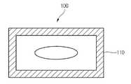
도 1은 영상표시장치의 수평 방향과 수직 방향으로 블랙 라인이 형성되어 있는 것을 나타내는 도면이다.1 is a diagram illustrating that black lines are formed in a horizontal direction and a vertical direction of an image display device.
즉, 수신되는 방송 프로그램의 종횡비에 따라서, 도 1과 같이 영상표시장치의 수평 방향 또는 수직 방향 또는 수평 방향과 수직 방향으로 동시에 블랙 라인이 형성되기 때문에, 사용자는 화면 전체를 시청할 수 없다는 불만족을 가지게 되는 문제점이 있었다.That is, according to the aspect ratio of the received broadcast program, black lines are simultaneously formed in the horizontal direction, the vertical direction, or the horizontal direction and the vertical direction of the video display device as shown in FIG. 1, so that the user may not be satisfied with the entire screen. There was a problem.
상기와 같은 문제점을 해결하기 위하여, 종래에 자동 종횡비 조정 방법(Auto Ratio Convert : ARC)이 개발되어 왔다.In order to solve the above problems, an automatic aspect ratio adjustment (ARC) method has been developed.
이와 같은 자동 종횡비 조정 방법(ARC)의 종래기술로는 대한민국공개특허 제10-2006-0008774호 및 대한민국공개특허 제10-2003-0093881호 등과 같은 기술이 제안된 바 있다. 이러한 기술은 PAL 신호의 wide 정보(WSS : Wide Screen Signaling, SCART ID) 또는 non linear scaling 또는 black line detector 등을 이용하여, 사용자에게 각각의 영상표시장치의 특성을 살린 풀 스크린(full screen)의 영상을 지원하기 위하여 제안되었다.As the prior art of such an automatic aspect ratio adjustment method (ARC) has been proposed techniques such as Korean Patent Publication No. 10-2006-0008774 and Korean Patent Publication No. 10-2003-0093881. This technology utilizes wide information (WSS: Wide Screen Signaling, SCART ID) of PAL signal or non linear scaling or black line detector to provide the user with full screen image that utilizes the characteristics of each image display device. It was offered to support.
그러나 상기 ARC를 무조건적으로 영상표시장치에 적용할 경우, 사용자가 원 영상 중에서 자신이 시청하고자 하는 영역만을 선택할 수 없기 때문에, 자신이 시청을 원하지 않는 영역까지 모두 시청하여야 하는 문제점이 존재하였다.
However, when the ARC is unconditionally applied to the image display device, since the user cannot select only the region that he / she wants to watch from the original image, there is a problem in that he / she should watch all the regions that he / she does not want to watch.
따라서, 본 발명의 목적은 한 화면을 통해 서로 다른 위치의 시청자에게 변화된 영상정보를 제공할 수 있고, 시청 위치의 변경만으로 시청을 원하는 영역을 선택할 수 있으며, 어느 위치에서 관찰하여도 시각적으로 우수한 영상정보를 제공할 수 있는 영상신호 출력장치를 제공하는데 있다.
Accordingly, an object of the present invention is to provide changed image information to viewers at different locations through one screen, to select an area to be watched only by changing the viewing position, and visually excellent at any position. An object of the present invention is to provide an image signal output apparatus capable of providing information.
상술한 본 발명의 목적을 달성하기 위하여, 본 발명의 일실시예에서는 외부로부터 입력된 방송신호를 시청자가 시청할 수 있도록 영상으로 출력하는 디스플레이 모듈을 포함하는 영상신호 출력장치에 있어서, 상기 디스플레이 모듈이 호 형상을 이루도록 배치된 복수개의 광원과, 상기 복수개의 광원에서 조사되는 광의 진행방향 상에 형성되어 특정방향으로 입사되는 광만을 투과시키는 필터부재, 및 상기 복수개의 광원이 연결되어 상기 광원의 출력정보를 조절하는 기판을 포함하는 것을 특징으로 하는 화면크기 보다 확장된 크기의 영상을 제공하는 영상신호 출력장치를 제공한다.
In order to achieve the above object of the present invention, in one embodiment of the present invention, in the video signal output device including a display module for outputting a broadcast signal input from the outside so that viewers can watch, the display module is A plurality of light sources arranged in an arc shape, a filter member which is formed on a traveling direction of light emitted from the plurality of light sources and transmits only light incident in a specific direction, and the plurality of light sources are connected to output information of the light source. It provides a video signal output device for providing an image of an expanded size than the screen size, characterized in that it comprises a substrate for controlling the.
본 발명에 의한 영상신호 출력장치를 사용하면, 화면의 크기보다 확장된 크기의 영상을 제공할 수 있다. 예를 들어, 월드컵 중계 시에 영상신호 출력장치를 정면에서 시청하는 시청자는 종래의 영상신호 출력장치와 동일한 내용의 화면을 시청할 수 있지만, 시청 위치를 좌우로 변경하면 처음 중계된 경기장의 좌우 측면을 시청할 수 있게 된다.Using the video signal output device according to the present invention, it is possible to provide an image of a size larger than the size of the screen. For example, a viewer watching the video signal output device from the front during the World Cup relay can watch the same screen as the conventional video signal output device. You can watch.
이와 같이, 본 발명은 한 화면의 크기와 동일한 크기의 영상을 시청자에게 제공할 수 있지만, 시청자의 관찰 위치에 따라 변화된 영상을 제공할 수 있으므로, 시청 위치를 변경하는 것만으로 시청을 원하는 영역을 간편하게 선택할 수 있게 된다. 따라서, 한 화면을 통해 경기장 전체에 대한 영상을 시청할 수 있게 한다.As described above, the present invention can provide the viewer with an image having the same size as the size of one screen, but can provide an image changed according to the viewing position of the viewer, so that the desired area can be easily viewed by simply changing the viewing position. You can choose. Therefore, it is possible to watch the image of the whole stadium through one screen.
다시 말해, 본 발명을 사용하면, 시청자는 예를 들면, 스마트 폰과 같은 작은 화면을 사용하더라도, 시청자가 시청위치를 바꾸게 되면 경기장의 구석구석에 대한 영상을 제공받을 수 있게 되어, 작은 크기의 디스플레이장치의 단점을 극복할 수 있데 된다.
In other words, using the present invention, even if the viewer uses a small screen such as a smart phone, when the viewer changes the viewing position, the viewer can be provided with an image of every corner of the stadium, and thus the display of the small size. It can overcome the disadvantages of the device.
도 1은 영상신호 출력장치의 수평 방향과 수직 방향으로 블랙 라인(black line)이 형성되어 있는 것을 나타내는 도면이다.
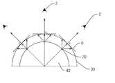
도 2는 본 발명의 일실시예에 따른 디스플레이 모듈을 설명하기 위한 개략도이다.
도 3은 본 발명의 일실시예에 따른 영상신호 출력장치를 나타내는 부분 확대 사시도이다.
도 4 및 도 5는 본 발명에 따른 영상신호 출력장치의 동작원리를 설명하기 위한 개략도이다.FIG. 1 is a diagram illustrating that black lines are formed in a horizontal direction and a vertical direction of a video signal output apparatus.
2 is a schematic diagram illustrating a display module according to an embodiment of the present invention.
3 is a partially enlarged perspective view illustrating a video signal output apparatus according to an embodiment of the present invention.
4 and 5 are schematic diagrams for explaining the operation principle of the image signal output apparatus according to the present invention.
이하, 첨부도면을 참조하여 본 발명의 바람직한 실시예들에 의한 화면크기 보다 확장된 크기의 영상을 제공하는 영상신호 출력장치(이하, '영상신호 출력장치'라고 한다.)를 상세하게 설명한다.
Hereinafter, with reference to the accompanying drawings will be described in detail a video signal output device (hereinafter referred to as "video signal output device") that provides an image of a larger size than the screen size according to the preferred embodiments of the present invention.
본 발명에 따른 영상신호 출력장치는 외부로부터 입력된 방송신호를 시청자가 인식할 수 있도록 영상이나 영상 및 음향으로 상기 방송신호를 출력하는 장치이다.The video signal output device according to the present invention is a device for outputting the broadcast signal as an image, video or sound so that the viewer can recognize the broadcast signal input from the outside.
도 2는 본 발명에 따른 영상신호 출력장치에 포함된 디스플레이 모듈을 설명하기 위한 구성도이다.2 is a block diagram illustrating a display module included in a video signal output apparatus according to the present invention.
도 2를 참조하면, 본 발명에 따른 디스플레이 모듈은 복수의 광원(20) 및 상기 복수의 광원(20)으로부터 일정간격 이격되어 광원(20)으로부터 조사되는 광을 특정방향으로 진행시키는 필터부재(30), 및 상기 복수개의 광원(20)이 연결되어 상기 광원(20)의 출력정보를 조절하는 기판(미도시)을 포함하며, 상기 광원(20)이 호 형상을 이루도록 배치될 수 있게 결합 공간을 제공하는 지지체(40)를 더 포함할 수 있다.Referring to FIG. 2, the display module according to the present invention includes a plurality of
상기 디스플레이 모듈을 제외한 영상신호 출력장치의 구성요소들은 이미 당업자들에게 널리 알려진 기술이므로, 종래와 다른 기능을 수행하는 구성요소를 제외한 일반적인 구성요소들에 대한 상세한 설명은 생략하도록 한다.
Since components of the image signal output apparatus other than the display module are well known to those skilled in the art, detailed descriptions of general components except components that perform functions different from those of the prior art will be omitted.
이하, 도면을 참조하여 각 구성요소별로 보다 구체적으로 설명한다.Hereinafter, each component will be described in more detail with reference to the drawings.
먼저 본 발명의 일실시예에 의한 디스플레이 모듈은 복수개의 광원(20)을 포함한다.First, the display module according to an embodiment of the present invention includes a plurality of
상기 복수개의 광원(20)은 외부로부터 입력된 방송신호가 출력장치의 화면을 통해 영상으로 출력될 수 있도록 빛을 발생시키는 것으로서, 다양한 색상을 자체적으로 발광할 수 있도록 LED 칩을 사용하는 것이 바람직하다. 이때, 상기 LED 칩은 칼라화상표시를 위해 적색(Red : R), 녹색(Green : G), 청색(Blue :B) 빛을 각각 발산하는 하나 이상의 R, G, B LED를 가지는 LED 단위유닛으로 형성될 수 있다. 상기 LED 단위유닛은 서로 이웃하며, 소정의 간격으로 기판의 상부에 탑재된다. 각 LED 단위유닛의 칼라별 LED는 공급되는 전원을 제어하는 기판의 제어에 따라 서로 독립적으로 구동되거나, 또는 동시에 구동되도록 마련될 수 있다. 다시 말해, LED 칩은 기판의 제어에 따라 각 R/G/B 광의 출력 세기가 조절하여 화상에 대응되도록 변조된 빛을 합성한다.The plurality of
또한, 복수개의 광원(20)은 시청자(2)의 위치에 따라 서로 다른 영상을 출력할 수 있도록 영상신호 출력장치의 내부에 호 형상을 이루도록 배치된다. 이때, 복수개의 광원(20)은 곡면 형상을 이루도록 배치될 수도 있다.In addition, the plurality of
보다 구체적으로, 복수개의 광원(20)은 반원, 원, 등의 호 형상으로 선을 따라 일렬로 배치되거나, 구형, 반구형, 원통형, 횡축 방향으로 절단된 반원통형, 횡축 방향으로 절단된 1/3 원통형 등의 곡면 형상으로 서로 일정간격 이격되도록 배치될 수 있지만, 이에 한정되지 않는다. 즉, 복수개의 광원(20)은 제작 의도에 따라 특정 형상, 예를 들면 타원 형상 등으로 배치될 수도 있다.
More specifically, the plurality of
그리고 본 발명의 일실시예에 의한 디스플레이 모듈은 기판을 포함한다.And the display module according to an embodiment of the present invention includes a substrate.
상기 기판은 복수개의 광원에 전기적으로 연결되어 상기 복수개의 광원의 출력정보를 조절하는 것으로서, 인쇄회로기판(Printed Circuit Board : PCB), 바람직하게는 연성회로기판(flexible pinted circuit board)이 사용될 수 있다.The substrate is electrically connected to a plurality of light sources to control output information of the plurality of light sources. A printed circuit board (PCB), preferably a flexible pinted circuit board, may be used. .
상기 기판은 복수개의 곡면 형상을 갖도록 형성되어 광원(20)이 직접 부착되거나, 복수개의 광원(20)이 부착된 지지체(40)들이 표면 또는 내부에 부착되도록 형성될 수 있다. 이때, 기판에는 개별 광원의 ID에 대한 정보가 저장되어 외부로부터 입력된 영상정보에 따라 개별 광원을 제어한다.The substrate may be formed to have a plurality of curved shapes so that the
또한, 기판은 열전도성 접착제를 통해 지지체(40)나 영상신호 출력장치의 외형을 제공하는 하우징(60)의 내부에 부착될 수 있다. 여기서, 열전도성 접착제는 기판으로부터 발열되는 열을 효율적으로 방출시킬 수 있어서 부품의 특성 변화를 최소화한다.In addition, the substrate may be attached to the
보다 구체적으로, 상기 기판은 베이스전극이 구비될 수 있다. 이러한 베이스전극은 구리, 금, 또는 은 등으로 구성될 수 있다. 또한, 기판은 베이스전극에 접속된 광원(20), 예를 들어 LED 칩에 각각 독립적으로 전원을 인가하여 각 LED 칩을 개별적으로 제어할 수 있는 구성을 가진다. 이때, 베이스전극은 복수개의 LED 칩이 일정배열로 설치될 수 있도록 일정배열로 기판에 구비된다.
More specifically, the substrate may be provided with a base electrode. The base electrode may be made of copper, gold, silver, or the like. In addition, the substrate has a configuration in which each LED chip can be individually controlled by applying power to the
그리고 본 발명의 일실시예에 의한 디스플레이 장치는 필터부재(30)를 포함한다.And the display device according to an embodiment of the present invention includes a filter member (30).
상기 필터부재(30)는 복수개의 광원(20)에서 조사되는 빛의 진행방향 상에 형성되어 상기 빛을 특정방향으로 진행시키는 역할을 수행하는 것으로서, 복수개의 광원(20)으로부터 조사되는 광원(20)이 서로 겹치지 않도록 제어하는 역할을 수행한다.The
다시 말해, 상기 필터부재(30)는 복수개의 광원(20)으로부터 조사된 광들이 진행경로를 따라 서로 겹치지 않게 조사될 수 있도록 빛의 진행경로를 제어함으로써, 영상신호 출력장치를 시청하는 시청자(2)의 위치에 따라 변화된 영상을 제공한다.In other words, the
상기 필터부재(30)로는 렌즈나 필름 등을 사용할 수 있으며, 특정적으로는 편광필름을 사용하는 것이 바람직하다.Lens or film may be used as the
보다 구체적으로, 필터부재(30)는 광원(20)으로부터 조사되어 필터부재(30)에 특정방향으로 입사된 빛만을 투과시킬 수 있다. 이러한 필터부재(30)는 도 2에 도시된 바와 같이 광원(20)들로부터 일정한 거리로 이격된 상태로 구비되어 조사된 빛들 중 필터부재(30)에 법선 방향으로 입사된 빛만을 투과시키는 역할을 수행한다. 결과적으로, 본 발명에 따른 디스플레이 모듈은 복수개의 광원(20)들의 개별 ID에 대한 정보가 기판에 저장되어 있고, 각 광원(20)들이 발광하는 빛의 이동경로가 필터부재에 의해 미리 설정될 수 있기 때문에, 시청자의 위치에 따라 상기 시청자가 입력받을 영상을 출력할 광원들을 미리 설정할 수 있다. 따라서, 영상신호 출력장치로 방송신호가 입력되면 기판은 입력된 방송신호에 따라 기 설정된 광원들에 발광할 빛을 분배하여 상기 광원들로부터 발광된 빛을 미리 설정된 위치로 출력시킨다.More specifically, the
선택적으로, 본 발명의 일실시예에 의한 디스플레이 장치는 지지체(40)를 더 포함할 수 있다.Optionally, the display device according to one embodiment of the present invention may further include a
상기 지지체(40)는 복수개의 광원이 호 형상이나 곡면 형상으로 배치될 수 있도록 곡면 형상의 안착공간을 제공하는 것으로서, 복수개의 광원 과 기판의 사이에 설치된다.The
또한, 지지체(40)는 시청자(2)의 위치에 따라 서로 다른 영상을 출력할 수 있도록 복수개의 광원(20)을 곡면 형상으로 영상신호 출력장치의 전면에 설치시킨다.In addition, the
보다 구체적으로, 지지체(40)는 표면에 상기 광원(20)이 호 형상을 이루도록 배치되거나 곡면 형상을 이루도록 배치될 수 있도록 곡면 형상을 갖는 입체로 형성된다. 예를 들어, 상기 지지체(40)는 구형, 반구형, 원통형, 수직 방향으로 절단된 반원통형, 수직 방향으로 절단된 1/3 원통형 등으로 형성될 수 있다. 또한, 지지체(40)는 타원을 갖는 입체로도 형성될 수 있다.More specifically, the
이러한 지지체(40)는 광원(20)이 착탈식으로 고정 또는 분리될 수 있도록 형성된다.The
도 3에 나타난 바와 같이 지지체(40)가 횡축을 기준으로 절단된 반원통형인 경우, 즉 종축을 기준으로 절단면이 반원의 형태로 형성되는 경우에는, 시청자의 시선이 좌우 방향으로 이동하여도 시청자(2)의 시야에 알맞은 영상을 제공할 수 있게 된다. 또한, 지지체(40)가 반구형인 경우에는 시청자의 시선이 좌우 방향 및 상하 방향으로 이동하여도 시청자의 시야에 알맞은 영상을 제공할 수 있게 된다.As shown in FIG. 3, when the
또한, 상기 지지체(40)는 그 표면에 필터부재(30)가 고정될 수 있도록 필터부재 고정수단(44)이 구비될 수 있다. 이때, 상기 필터부재 고정수단(44)은 지지체(40)로부터 일정한 거리로 이격되도록 상기 필터부재(30)를 고정시킬 수 있다면 어떠한 형태로 형성되어도 무방하다.In addition, the
아울러, 각각의 지지체(40)는 도 3에 도시된 바와 같이 영상신호 출력장치의 전면에 일정한 간격을 갖도록 배치된다. 그리고 복수의 지지체(40)는 평판형 지지판(미도시)에 모두 부착되거나 결합되도록 형성될 수 있다. 예를 들어, 도 3에 도시된 지지체(40)는 평판형 지지판에 접촉되는 부분이 사각형 형태인 표면이다. 이때, 평판형 지지판은 영상신호 출력장치의 하우징(60)의 내부에 고정될 수 있도록 형성된다.In addition, each
필요에 따라, 지지체(40)는 평판형 지지판에 원활하게 부착되어 고정될 수 있도록 상기 평판형 지지판과 접촉되는 표면에 접착제가 구비될 수 있으며, 상기 지지체(40)와 평판형 지지판은 일체형으로 형성될 수도 있다.
If necessary, the
도 4 및 도 5는 본 발명에 따른 영상신호 출력장치의 동작원리를 설명하기 위한 개략도이다. 도 4 및 도 5를 참조하여, 본 발명에 의한 영상신호 출력장치의 동작원리를 살펴보면 다음과 같다.4 and 5 are schematic diagrams for explaining the operation principle of the image signal output apparatus according to the present invention. 4 and 5, the operation principle of the image signal output apparatus according to the present invention will be described.
도 4를 참조하면, 본 발명에 따른 디스플레이 모듈(10)을 구성하는 복수의 광원(20)들로부터 조사되는 빛들은 필터부재(30)에 의해 진행경로가 결정되어져 있어 임의의 제 1 위치의 시청자(2')에게 빛을 조사하여 영상정보를 출력하는 광원(20)들은 임의의 제 2 위치의 시청자(2")에게 빛을 조사하지 못한다. 이와 같이, 본 발명에 따른 디스플레이 모듈(10)은 시청자의 위치에 따라 상기 시청자에 빛을 조사하는 각 광원(20)이 서로 다를 뿐만 아니라, 각 광원(20)은 기판(50)의 제어에 의해 서로 다른 색상의 빛을 출력할 수 있으므로, 시청자(2)는 위치에 따라 변화된 영상정보를 제공받을 수 있게 된다. 이를 위해, 상기 기판(50)에는 각 광원(20)의 동작을 제어하기 위한 제어부가 구비된다. 이러한 제어부는 IC 회로로 이루어지거나, 소프트웨어가 설치된 마이컴으로 이루어진다.Referring to FIG. 4, the light paths irradiated from the plurality of
예를 들어, A영역과 B영역과 C영역으로 이루어진 경기장을 복수개의 영상촬영장비로 촬영하고, 상기 영상촬영장비로부터 수집된 영상정보를 보정하여 하나의 영상으로 변환한 다음, 이러한 영상을 방송신호로 송출하는 경우, 상기 방송신호를 수신한 본 발명에 따른 영상신호 출력장치의 제어부는 시청자의 위치에 따라 경기장의 서로 다른 영상을 제공하도록 동작한다.For example, a stadium consisting of a region A, a region B, and a region C is photographed with a plurality of video photographing equipment, the video information collected from the video photographing equipment is corrected, converted into a single video, and the video is broadcasted. In the case of transmitting the video signal, the control unit of the video signal output apparatus according to the present invention receiving the broadcast signal operates to provide different images of the stadium according to the viewer's position.
보다 구체적으로, 기판(50)은 영상신호 출력장치의 정면에 위치한 시청자(2')가 A영역에 해당하는 영상을 인식할 수 있도록 A영역에 빛을 조사하도록 기 설정된 복수개의 광원(20)을 제어한다. 그리고 기판(50)은 영상신호 출력장치의 정면 왼쪽에 위치한 시청자(2")가 B영역에 해당하는 영상을 인식할 수 있도록 B영역에 빛을 조사하도록 기 설정된 복수개의 광원을 제어한다. 또한, 기판(50)은 영상신호 출력장치의 정면 오른쪽에 위치한 시청자(2^)가 C영역에 해당하는 영상을 인식할 수 있도록 C영역에 빛을 조사하도록 기 설정된 복수개의 광원(20)을 제어한다. 이때, A영역과 B영역 및 C영역에 대한 영상을 출력하는 광원은 서로 다르다.More specifically, the
즉, 각 광원(20)으로부터 조사되는 빛의 진행경로가 결정되어 있고, 각 광원(20)에 대한 ID가 기판에 저장되어 있으므로, 기판(50)은 출력해야 될 영상에 대한 데이터를 방송신호로부터 추출하여 여러 방향으로 서로 다른 영상을 제공할 수 있다. 따라서, 시청자는 시청 위치의 변경만으로 시청을 원하는 영역, 예를 들어 A, B, 또는 C를 선택할 수 있다.That is, since the propagation path of the light irradiated from each
다시 말해, 시청자는 영상신호 출력장치에 대한 시청 위치에 따라 상기 영상신호 출력장치로부터 서로 다른 영상정보를 제공받을 수 있기 때문에, 스포츠 경기 등을 관람하는 경우 시청 위치를 변경하는 것만으로 시청을 원하는 영역을 간편하게 선택할 수 있게 된다.
In other words, the viewer can receive different image information from the video signal output device according to the viewing position of the video signal output device. Therefore, when watching a sports event or the like, the viewer wants to watch the video only by changing the viewing position. You can easily select.
또한, 도 5에 도시된 바와 같이 본 발명의 디스플레이 모듈(10)은 빛의 진행경로가 미리 설정된 광원(20)들을 통해 방송신호에 대한 영상을 출력하고 있기 때문에, 디스플레이 모듈(10)에 인접한 위치로 이동한 시청자(2')는 A영역, B영역, C영역을 모두 시청할 수 있는 반면, 디스플레이 모듈(10)로부터 멀어진 위치로 이동한 시청자(2")는 시청할 수 있는 B영역과 C영역이 줄어들다가 결국 A영역만을 시청할 수 있게 된다.
In addition, as shown in FIG. 5, the
이상에서 본 발명의 바람직한 실시예를 참조하여 설명하였지만, 해당 기술분야의 숙련된 당업자는 하기의 특허청구범위에 기재된 본 발명의 사상 및 영역으로부터 벗어나지 않는 범위 내에서 본 발명을 다양하게 수정 및 변경시킬 수 있음을 이해할 수 있을 것이다.Although the above has been described with reference to the preferred embodiments of the present invention, those skilled in the art will be able to variously modify and change the present invention without departing from the spirit and scope of the invention as set forth in the claims below. It will be appreciated.
2 : 시청자4 : 영상신호 출력장치
10 : 디스플레이 모듈20 : 광원
30 : 필터부재40 : 지지체2: viewer 4: video signal output device
10: display module 20: light source
30
Claims (7)
Translated fromKorean상기 디스플레이 모듈이 호 형상을 이루도록 배치된 복수개의 광원;
상기 복수개의 광원으로부터 조사되는 빛의 진행방향 상에 형성되어 특정방향으로 입사되는 빛만을 투과시키는 필터부재; 및
상기 복수개의 광원이 연결되어 상기 방송신호에 따라 상기 광원의 출력정보를 조절하는 기판을 포함하는 것을 특징으로 하는 화면크기 보다 확장된 크기의 영상을 제공하는 영상신호 출력장치.In the video signal output device comprising a display module for outputting a broadcast signal input from the outside as an image so that the viewer can recognize,
A plurality of light sources arranged to form the display module in an arc shape;
A filter member formed on a traveling direction of light emitted from the plurality of light sources and transmitting only light incident in a specific direction; And
And a substrate for controlling the output information of the light source according to the broadcast signal by connecting the plurality of light sources.
LED 칩을 포함하는 것을 특징으로 하는 화면크기 보다 확장된 크기의 영상을 제공하는 영상신호 출력장치.The method of claim 1, wherein the light source
Image signal output device for providing an image of an expanded size than the screen size, characterized in that it comprises an LED chip.
복수개의 곡면 형상을 갖도록 형성되며, 상기 복수개의 광원이 상기 곡면 형상에 설치되는 것을 특징으로 하는 화면크기 보다 확장된 크기의 영상을 제공하는 영상신호 출력장치.The method of claim 1, wherein the substrate
And a plurality of light sources, wherein the plurality of light sources are installed in the curved shape to provide an image having an enlarged size than the screen size.
Priority Applications (1)
| Application Number | Priority Date | Filing Date | Title |
|---|---|---|---|
| KR1020110005497AKR101028930B1 (en) | 2011-01-19 | 2011-01-19 | Video signal output device that provides an image of expanded size than the screen size |
Applications Claiming Priority (1)
| Application Number | Priority Date | Filing Date | Title |
|---|---|---|---|
| KR1020110005497AKR101028930B1 (en) | 2011-01-19 | 2011-01-19 | Video signal output device that provides an image of expanded size than the screen size |
Publications (1)
| Publication Number | Publication Date |
|---|---|
| KR101028930B1true KR101028930B1 (en) | 2011-04-12 |
Family
ID=44050041
Family Applications (1)
| Application Number | Title | Priority Date | Filing Date |
|---|---|---|---|
| KR1020110005497AActiveKR101028930B1 (en) | 2011-01-19 | 2011-01-19 | Video signal output device that provides an image of expanded size than the screen size |
Country Status (1)
| Country | Link |
|---|---|
| KR (1) | KR101028930B1 (en) |
Cited By (1)
| Publication number | Priority date | Publication date | Assignee | Title |
|---|---|---|---|---|
| WO2013183947A1 (en)* | 2012-06-05 | 2013-12-12 | 엘지전자 주식회사 | Method and apparatus for processing broadcast signals for 3d broadcast service |
Citations (4)
| Publication number | Priority date | Publication date | Assignee | Title |
|---|---|---|---|---|
| KR20080044896A (en)* | 2005-09-06 | 2008-05-21 | 후지쓰 텐 가부시키가이샤 | Display device and display method |
| KR20080058974A (en)* | 2006-12-23 | 2008-06-26 | 엘지디스플레이 주식회사 | Flat panel display controllable viewing angle and multi-view |
| KR20100080032A (en)* | 2008-12-31 | 2010-07-08 | 엘지디스플레이 주식회사 | Multi view display device |
| KR20100126026A (en)* | 2009-05-22 | 2010-12-01 | 엘지전자 주식회사 | Portable terminal with multi-view display and control method thereof |
- 2011
- 2011-01-19KRKR1020110005497Apatent/KR101028930B1/enactiveActive
Patent Citations (4)
| Publication number | Priority date | Publication date | Assignee | Title |
|---|---|---|---|---|
| KR20080044896A (en)* | 2005-09-06 | 2008-05-21 | 후지쓰 텐 가부시키가이샤 | Display device and display method |
| KR20080058974A (en)* | 2006-12-23 | 2008-06-26 | 엘지디스플레이 주식회사 | Flat panel display controllable viewing angle and multi-view |
| KR20100080032A (en)* | 2008-12-31 | 2010-07-08 | 엘지디스플레이 주식회사 | Multi view display device |
| KR20100126026A (en)* | 2009-05-22 | 2010-12-01 | 엘지전자 주식회사 | Portable terminal with multi-view display and control method thereof |
Cited By (3)
| Publication number | Priority date | Publication date | Assignee | Title |
|---|---|---|---|---|
| WO2013183947A1 (en)* | 2012-06-05 | 2013-12-12 | 엘지전자 주식회사 | Method and apparatus for processing broadcast signals for 3d broadcast service |
| CN104584547A (en)* | 2012-06-05 | 2015-04-29 | Lg电子株式会社 | Method and apparatus for processing broadcast signals for 3D broadcast service |
| US9900578B2 (en) | 2012-06-05 | 2018-02-20 | Lg Electronics Inc. | Method and apparatus for processing broadcast signals for 3D broadcast service |
Similar Documents
| Publication | Publication Date | Title |
|---|---|---|
| KR101974995B1 (en) | System and method for displaying captions | |
| US20120038689A1 (en) | Display Device and Illumination Control Method | |
| JP2007065067A (en) | Stereoscopic image display device | |
| JPWO2009028168A1 (en) | Video-linked lighting control system and video-linked lighting control method | |
| MX2009012857A (en) | Three-dimensional television system, three-dimensional television receiver and three-dimensional image watching glasses. | |
| US20110115888A1 (en) | Broadcast receiving apparatus and control method therefor | |
| US9210325B2 (en) | Video signal and tally signal switcher system | |
| US8305426B2 (en) | Stereoscopic video display apparatus and method therefor | |
| US20160366390A1 (en) | Ultra high definition 3d conversion device and an ultra high definition 3d display system | |
| US20120147154A1 (en) | Stereoscopic Video Display Apparatus and Method Therefor | |
| JP2011082982A (en) | System for providing multi-angle broadcasting service | |
| KR101028930B1 (en) | Video signal output device that provides an image of expanded size than the screen size | |
| US9774840B2 (en) | Stereoscopic video signal processing apparatus and method thereof | |
| US20130321577A1 (en) | Stereoscopic Video Signal Processing Apparatus and Method Therefor | |
| CN215345144U (en) | Multifunctional television atmosphere lamp | |
| CN102340680B (en) | Image playing system, correlated apparatus thereof and methods thereof | |
| CN105744196A (en) | Non-screen television capable of dual-channel playing | |
| KR101832225B1 (en) | Image display apparatus, and method for operating the same | |
| JP2012003123A (en) | Stereoscopic video display device | |
| KR102437858B1 (en) | A crowd control system that controls a plurality of user terminals | |
| US20110316992A1 (en) | Image Playback System, Associated Apparatus and Method Thereof | |
| JPH1198342A (en) | Panoramic image display method and apparatus | |
| JP2015039063A (en) | Video processing apparatus and video processing method | |
| KR20180064010A (en) | System for controlling lighting using broadcasting supplement service | |
| KR101917277B1 (en) | Camera module structure and electronic device having the same |
Legal Events
| Date | Code | Title | Description |
|---|---|---|---|
| A201 | Request for examination | ||
| PA0109 | Patent application | Patent event code:PA01091R01D Comment text:Patent Application Patent event date:20110119 | |
| PA0201 | Request for examination | ||
| A302 | Request for accelerated examination | ||
| PA0302 | Request for accelerated examination | Patent event date:20110322 Patent event code:PA03022R01D Comment text:Request for Accelerated Examination Patent event date:20110119 Patent event code:PA03021R01I Comment text:Patent Application | |
| E701 | Decision to grant or registration of patent right | ||
| PE0701 | Decision of registration | Patent event code:PE07011S01D Comment text:Decision to Grant Registration Patent event date:20110401 | |
| GRNT | Written decision to grant | ||
| PR0701 | Registration of establishment | Comment text:Registration of Establishment Patent event date:20110405 Patent event code:PR07011E01D | |
| PR1002 | Payment of registration fee | Payment date:20110405 End annual number:3 Start annual number:1 | |
| PG1601 | Publication of registration | ||
| FPAY | Annual fee payment | Payment date:20140408 Year of fee payment:4 | |
| PR1001 | Payment of annual fee | Payment date:20140408 Start annual number:4 End annual number:4 | |
| FPAY | Annual fee payment | Payment date:20160504 Year of fee payment:6 | |
| PR1001 | Payment of annual fee | Payment date:20160504 Start annual number:6 End annual number:6 | |
| FPAY | Annual fee payment | Payment date:20161230 Year of fee payment:7 | |
| PR1001 | Payment of annual fee | Payment date:20161230 Start annual number:7 End annual number:7 | |
| FPAY | Annual fee payment | Payment date:20190327 Year of fee payment:9 | |
| PR1001 | Payment of annual fee | Payment date:20190327 Start annual number:9 End annual number:9 | |
| PR1001 | Payment of annual fee | Payment date:20200330 Start annual number:10 End annual number:10 | |
| PR1001 | Payment of annual fee | Payment date:20210422 Start annual number:11 End annual number:11 | |
| PR1001 | Payment of annual fee | Payment date:20220317 Start annual number:12 End annual number:12 | |
| PR1001 | Payment of annual fee | Payment date:20230926 Start annual number:13 End annual number:13 | |
| PR1001 | Payment of annual fee | Payment date:20240325 Start annual number:14 End annual number:14 |